

Before attempting to connect or operate this product, please read these instructions completely.
Ceiling Mount Bracket
WV-Q106E
The model numbers listed in this Operating Instructions have no suffixed attached to it.
PREFACE
The Panasonic Ceiling Mount Bracket WV-Q106 is provided for the surface mounting of the
Combination Camera WV-CS600 or WV-CS400 on a suspended (double) ceiling.
PRECAUTION
• Do mount this bracket in a suspended
ceiling having a minimum of 180 mm
(18 cm) clearance.
• The ceiling board thickness to mount
this bracket can be a maximum of 40
mm (4 cm) in thickness.
• Be sure to use the Fall Prevention Wire
(provided).
• Be sure to use the Camera Fixing
Screw (provided with the camera) to
mount the camera into this bracket.
INSTALLATIONS
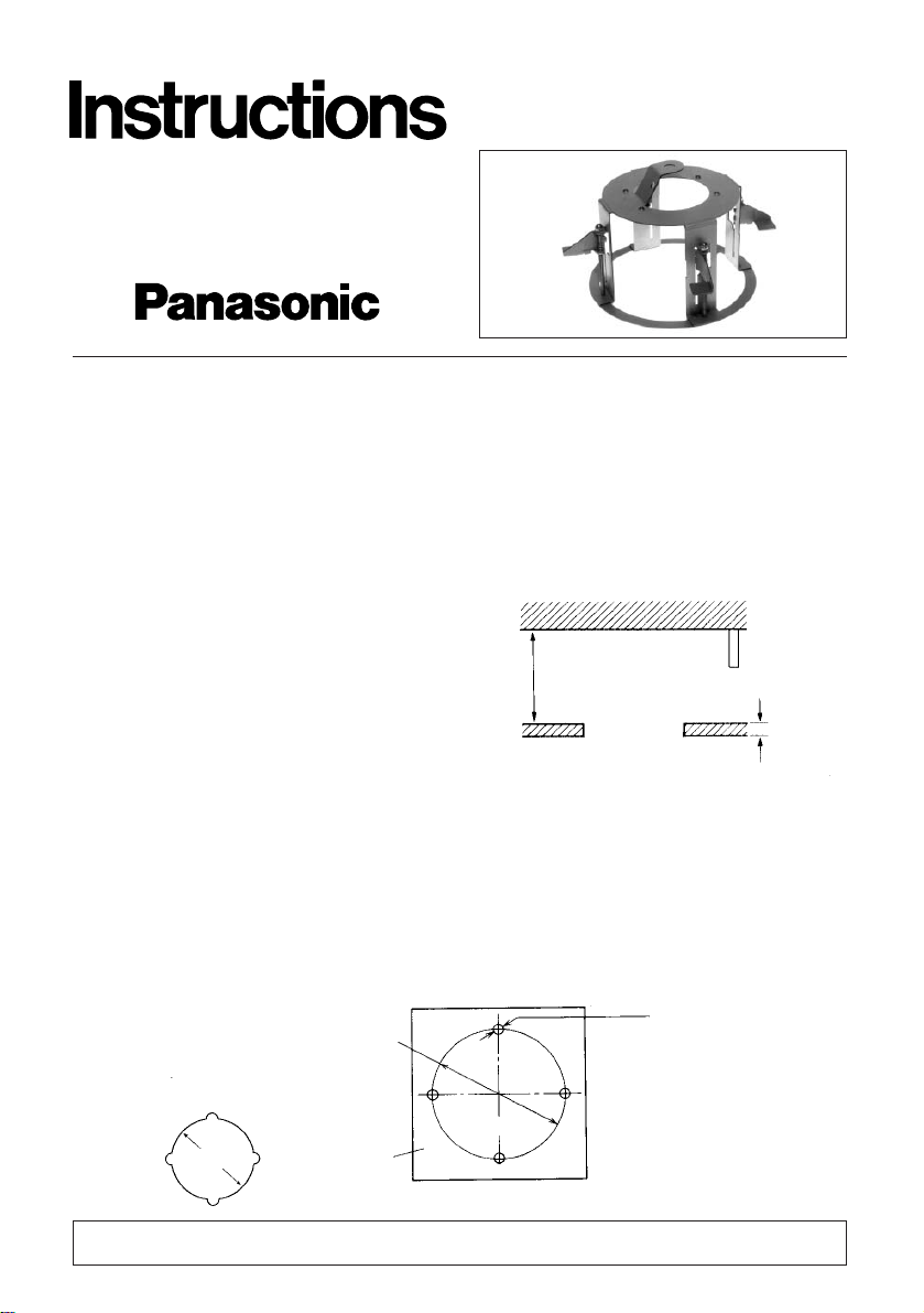
1. Make holes in the suspended ceiling by using the Template-A (provided).
1-1. Make four holes (φ12 mm x 4) and remove the "C" area.
1-2. A mounting slot (φ160 mm) is made as shown in the following.
In Ceiling
Minimum 180 mm
Suspended
Ceiling
Maximum 40mm
4-φ12mm
φ160mm
Template A
φ160mm
"C"
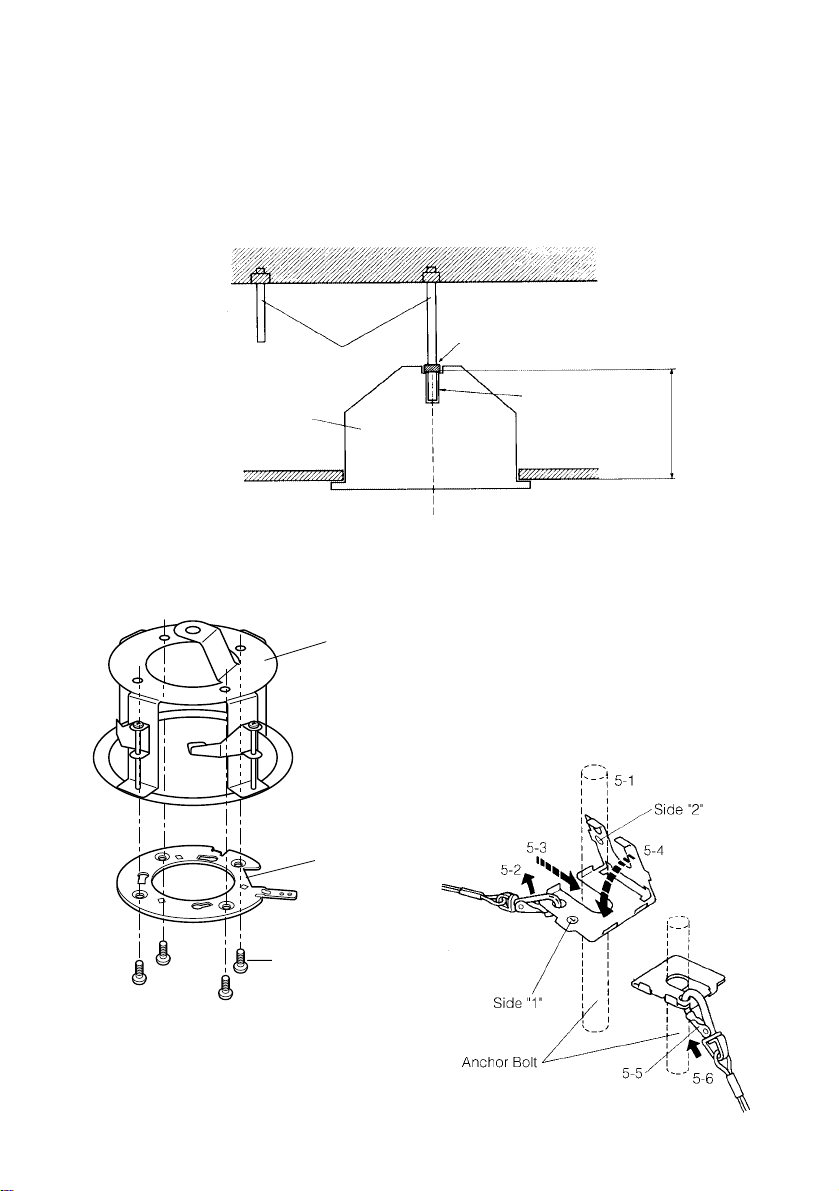
2. Drive a standard Anchor Bolt (#1 in illustration) into the centre of a slot made in the top
ceiling, as shown in step 1.
Drive another Anchor Bolt (#2 in illustration) into the relative second position as shown
in the following.
3. Attach one standard anchor nut at the "D" point measured by the Template-B (provided).
Measure the "E" length by using the Template-B.
4. Mount the Camera Mounting Angle
(provided with camera) onto this bracket by using the four Camera Mounting
Angle Fixing Screws (provided).
5-1. Put a standard anchor nut into the
Anchor Bolt (2).
5-2. Remove the Bracket Fall
Prevention Wire from the Bracket
Fall Prevention Angle Clip.
5-3. Insert the Anchor Bolt (2) through
the side "1".
5-4. Fold (exert manual pressure) the
side "2" down onto the side "1"
(When folded properly side "1" and
side "2" should be matched.).
Anchor Bolt
Template B
"E"
"D"
136 mm
Suspended Ceiling
(2)
(1)
WV-Q106
Camera
Mounting
Angle
M4-L8 (provided)
5. Attach the Bracket Fall Prevention
Angle Clip (provided) to the Anchor
Bolt (2) according to the following step.
Notice the "L-shaped" clip has side "1"
and side "2", and must be manually
bent into position during installation for
correct placement.
- 2 -

- 3 -
5-5. Reattach the removed Bracket Fall
Prevention Wire into the "matched"
holes of the side "1" and "2".
5-6. Put two standard anchor nuts into
the Anchor Bolt (2).
5-7. Tighten three nuts to fix the Fall
Prevention Angle Clip.
6. Hang the Camera Mount Bracket from
the other end of the Fall Prevention
Wire.
8. Mount the bracket onto the Anchor Bolt
(1).
9. Fix the camera mount bracket into the
suspended ceiling by rotating four
Camera Mount Bracket Fixing Screws
to clockwise.
Insert one large washer (provided) and
two anchor nuts to securely suspend
the Camera Mount Bracket, and tighten
these securely into place.
7. Put the connected bracket into the suspended ceiling through a slot.
Fall Prevention
Wire
Anchor Nut
Nuts
Rotate clockwise
10. Cut the Diecast Case as shown below.
Note: Be sure to cover the video and
power cables by using the Protection Cover (provided).
Protection Cover
(provided)
Cut here

- 4 -
Note: Be sure to match the wire with the
Fall Prevention Wire Fixing Angle as
shown below.
Fall Prevention Wire
Fixing Angle
Ring of the Fall
Prevention Wire
11. Hang the Fall Prevention Wire to the
Camera Mounting Angle.
Fall Prevention
Wire
12. Put the power and video cables into
the ceiling.
13. Mount the camera to the Camera Fixing
Angle by the Camera Fixing Angle
Mounting Screw (provided with the
camera).
Note: When removing the Camera from
the Camera Mounting Angle,
loosen the Camera Fixing Screw
(M3) and press up it by using the
screw driver.
Camera Mounting Angle
Fixing Screws (M2)
Fixing Angle
Camera
Mounting Angle
Camera
Press up
2
1

- 5 -
14. Mount the Decoration Cover onto the
camera.
Refer to the Operating Instructions of
the combination Camera WV-CS400 or
WV-CS600 for mounting the camera.
Press up the Decoration Cover of the
camera with matching these tags of
this bracket to the projections of the
Decoration Cover.
Tags
Match the tags
to the projections
Projections
15. Rotate the Decoration Cover of the
camera to clockwise.
SPECIFICATIONS
Ambient Operating Temperature : −10° C - +50°C (14° F - 122° F)
Dimensions : φ184 x 145 (D) mm
Weight : 500g
Weight and dimensions indicated are approximate.
Specifications are subject to change without notice.
ACCESSORIES
Fall Prevention Wire ...................................................... 1 pc.
Fall Prevention Angle Clip ............................................ 1 pc.
Template A.................................................................... 1 pc.
Template B.................................................................... 1 pc.
Camera Mounting Angle Fixing Screw ....................... 4 pcs.
Protection Cover ........................................................... 1 pc.
 Loading...