

Page 1
Before attempting to connect or operate this product,
please read these instructions carefully and save this manual for future use.
Model No. WV-PS154
Camera Drive Unit
Operating Instructions
P
O
W
E
R
P
O
W
ER
LE
D
W
ILL F
LA
SH
IF C
O
O
LIN
G
F
AN
M
ALT
IFU
N
C
TIO
N
Camera Drive Unit WV-PS
154
O
N
O
F
F
FRANÇAIS
ENGLISH
Page 2
The serial number of this product may be found on the bottom of the unit.
You should note the serial number of this unit in the space
provided and retain this book as a permanent record of your
purchase to aid identification in the event of theft.
Model No.
Serial No.
WARNING:
To reduce the risk of fire or electric shock, do not expose this appliance to rain or moisture.
The lightning flash with arrowhead symbol, within an equilateral triangle, is
intended to alert the user to the presence of uninsulated "dangerous voltage"
within the product's enclosure that may
be of sufficient magnitude to constitute a
risk of electric shock to persons.
The exclamation point within an equilateral triangle is intended to alert the user
to the presence of important operating
and maintenance (servicing) instructions
in the literature accompanying the appliance.
CAUTION: TO REDUCE THE RISK OF ELECTRIC SHOCK,
DO NOT REMOVE COVER (OR BACK).
NO USER-SERVICEABLE PARTS INSIDE.
REFER SERVICING TO QUALIFIED SERVICE PERSONNEL.
CAUTION
RISK OF ELECTRIC SHOCK
DO NOT OPEN
SA 1965
SA 1966
NOTE: This equipment has been tested and found to comply
with the limits for a Class A digital device, pursuant to Part
15 of the FCC Rules. These limits are designed to provide
reasonable protection against harmful interference when the
equipment is operated in a commercial environment. This
equipment generates, uses, and can radiate radio frequency
energy and, if not installed and used in accordance with the
instruction manual, may cause harmful interference to radio
communications.
Operation of this equipment in a residential area is likely to
cause harmful interference in which case the user will be
required to correct the interference at his own expense.
FCC Caution: To assure continued compliance, (example use only shielded interface cables when connecting to computer or peripheral devices). Any changes or modifications
not expressly approved by the party responsible for compliance could void the user’s authority to operate this equipment.
For U.S.A
Caution:
Before attempting to connect or operate this product,
please read the label on the bottom.
CONTENTS
PREFACE ...................................................................................................................................................................................... 3
FEATURES .................................................................................................................................................................................... 3
PRECAUTIONS ............................................................................................................................................................................. 3
MAJOR OPERATING COMPONENTS AND THEIR FUNCTIONS ................................................................................................. 4
■ Front View ............................................................................................................................................................................... 4
■ Rear View ............................................................................................................................................................................... 4
INSTALLATION ............................................................................................................................................................................. 5
■ Mounting in the rack ............................................................................................................................................................... 5
SYSTEM CONNECTION ................................................................................................................................................................ 6
SPECIFICATIONS ........................................................................................................................................................................ 10
STANDARD ACCESSORIES
................................................................................................................................................................. 10
ENGLISH VERSION
Page 3

3
PREF ACE
FEATURES
The Panasonic WV-PS154 Camera Drive Unit drives up to
four VP (Video and Power) multiplex cameras.
This simple system is designed to meet the surveillance
and security needs of offices, factories, public and residential buildings, etc.
• Up to four VP multiplex cameras of the specified model
can be driven by one WV-PS154.
• A single coaxial cable connects cameras of the speci-
fied model and camera inputs to the Camera Drive Unit.
It supplies DC power, controls data and vertical drive
pulses to the cameras, and receives video and audio
(*) signals from the cameras.
(*) If an applicable camera is connected.
• Controls camera setup through the specified outboard
device connected.
• VD/SYNC IN and OUT connectors provided for synchronizing in parallel connection.
• Refer all work related to the installation of this
product to qualified service personnel or system
installers.
• Do not block the ventilation opening or slots on the
cover.
To prevent the appliance temperature from rising, place
the appliance at least 5 cm (2 inches) away from the
wall.
• Do not drop metallic parts through slots.
This could permanently damage the appliance. Turn
the power off immediately and refer servicing to
qualified service personnel.
• Do not attempt to disassemble the appliance.
To prevent electric shock, do not remove screws or
covers.
There are no user-serviceable parts inside. Refer maintenance to qualified service personnel.
• Handle the appliance with care.
Do not strike or shake, as this may damage the appliance.
• Do not expose the appliance to water or moisture,
nor try to operate it in wet areas.
Do take immediate action if the appliance becomes
wet. Turn the power off and refer servicing to qualified
service personnel. Moisture can damage the appliance
and also cause electric shock.
• Do not use strong or abrasive detergents when
cleaning the appliance body.
Use a dry cloth to clean the appliance when it is dirty.
When the dirt is hard to remove, use a mild detergent
and wipe gently.
• Do not operate the appliance beyond its specified
temperature, humidity or power source ratings.
Do not use the appliance in an extreme environment
where high temperature or high humidity exists.
Use the appliance at temperatures within -10°C +50°C (14°F - 122°F) and a humidity below 90 %.
The input power source for this appliance is 120 V AC
60 Hz.
PRECAUTIONS
ENGLISH
Page 4
4
POWER LED WILL FLASH
IF COOLING FAN MALFUNCTIONS
SWITCH
PROTECTOR
Camera Drive Unit WV-PS
Power
ON
OFF
q
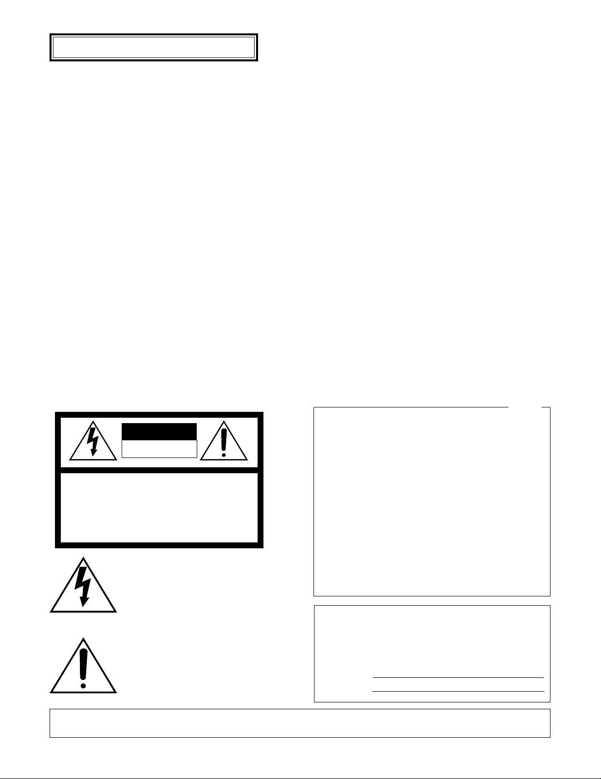
q Power On/Off Switch (POWER ON/OFF)
This switch is used to turn the camera drive unit and
connected cameras on and off. The indicator lights up
when the camera drive unit is switched on.
When turns this switch off, the power supply does not
interrupt. In such a case, disconnect the AC cord or
turn the circuit breaker off.
Note: To prevent accidental interruption of power sup-
ply to the camera drive unit, cover the power switch
with the supplied switch protector as shown below.
t VD/SYNC Input Connector (VD/SYNC IN)
The VD (Vertical Drive) pulse or VS (Video Sync) signal
is supplied to this connector for synchronizing the system.
y VD/SYNC Output Connector (VD/SYNC OUT)
The VD (Vertical Drive) pulse or VS (Video Sync) signal
is output from this connector for synchronizing other
system components.
Note: Be sure that the specified camera and camera
input1 are connected correctly and firmly. The synchronizing signal is not supplied if this connection is
faulty.
u Cooling Fan
This unit prevents the temperature of the camera drive
unit from rising
Caution:
Do not block the ventilation opening or slots on the
cover to prevent the temperature of the camera drive
unit from rising. The power indicator blinks to indicate
an unusual temperature rise. Do take immediate
action when the power indicator blinks. Turn the
power off and refer servicing to qualified service personnel.
The cooling fan inside the camera drive unit is subject
to wear and need to be replaced periodically.
i AC Cord
o Signal Ground Terminal (SIGNAL GND)
w Camera Input Connectors (CAMERA IN 1, 2, 3, 4)
These connectors receive color or B/W composite video
signals from the cameras. They also supply DC power
and vertical drive pulses for synchronizing signals to
the cameras and receive video and audio signals from
the cameras.
e Video Output Connectors (VIDEO OUT 1, 2, 3, 4)
Video signals from the cameras are output from these
connectors for input to outboard devices.
r Audio Output Connectors (AUDIO OUT 1, 2, 3, 4)
Audio signals from the cameras are output from these
connectors for input to the outboard devices (if an
applicable camera is connected).
SWITCH
PROTECTOR
MAJOR OPERATING CONTROLS AND THEIR FUNCTIONS
■ Front View
w
4321 432
21
43
1
(4V[p-p]75Ω)
SIGNAL
GND
VD/SYNC
OUT
VD/SYNC
IN
VIDEO OUT AUDIO OUTCAMERA IN
e t o
r y u i
■ Rear View
Page 5
5
INSTALLATION
■ Mounting in the Rack
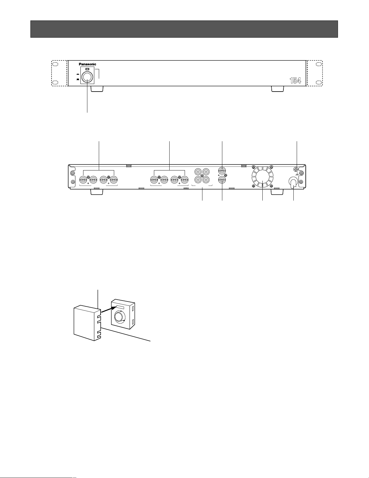
1. Remove the four rubber feet by removing the four
screws on the bottom of the camera drive unit.
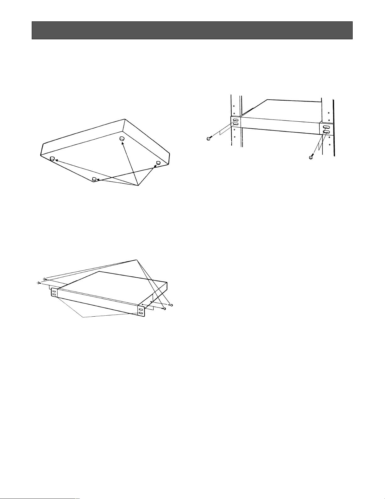
2. Place the rack mounting brackets on both sides of the
camera drive unit and tighten the six supplied screws
(M3x10).
3. Install the camera drive unit with the rack mounting
brackets on the rack using four screws (not supplied).
Cautions:
• Do not block the ventilation opening or slots in the
cover to prevent the appliance from overheating.
• Always keep the inside rack temperature below
45°C (113° F).
• The cooling fan inside the camera drive unit is subject to wear and need to be replaced periodically.
• Secure the rear of the appliance to the rack by
using additional mounting brackets (procured
locally) if the rack is subject to vibrations.
Remove 4 rubber feet
Six screws (Supplied)
Fix the rack mounting brackets
The installations described below should be made by
qualified service personnel or system installers.
Page 6
6
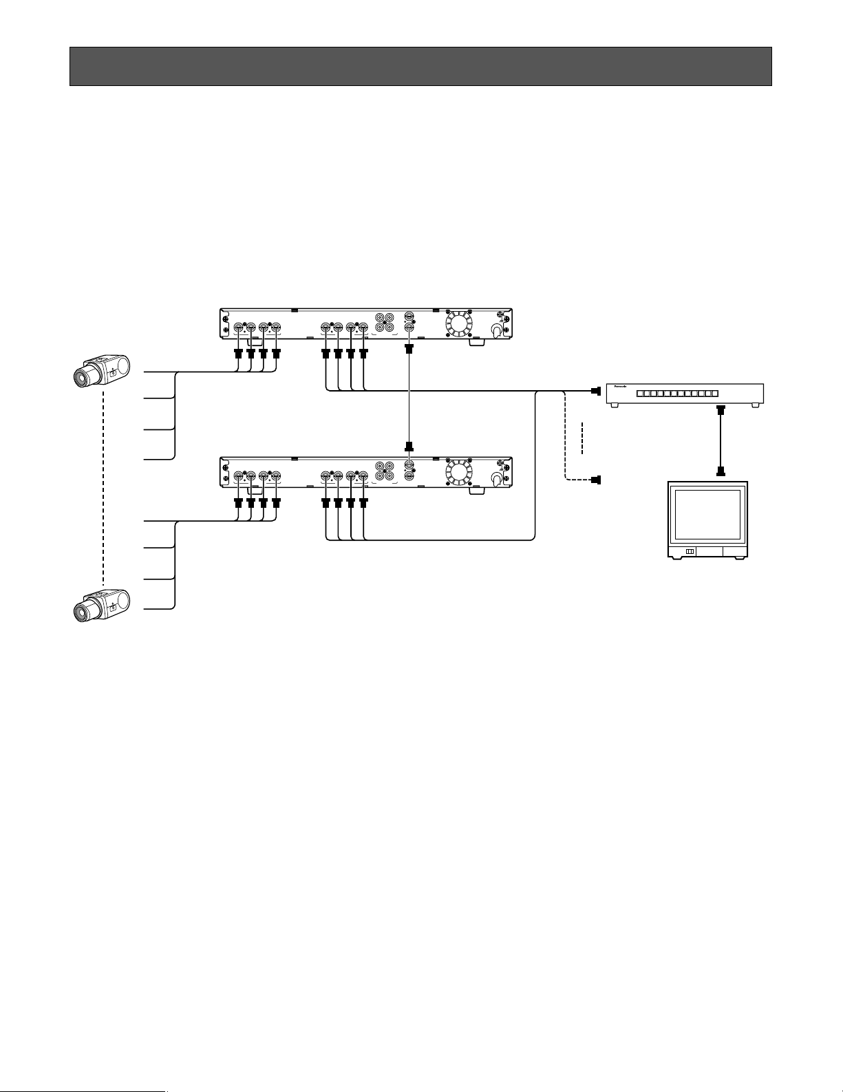
<Extended System >
4321 432
21
43
1
(4V[p-p]75Ω)
SIGNAL
GND
VD/SYNC
OUT
VD/SYNC
IN
VIDEO OUT AUDIO OUTCAMERA IN
4321 432
21
43
1
(4V[p-p]75Ω)
SIGNAL
GND
VD/SYNC
OUT
VD/SYNC
IN
VIDEO OUT AUDIO OUTCAMERA IN
1ch
8ch
1
2
3
4
Camera
Camera
5
6
7
8
CAMERA IN
VIDEO OUT
654321 7 8 9 10 11 12
Video Switcher
VIDEO
OUT
CAMERA IN
Camera Drive Unit WV-PS154
VD/SYNC
Camera Drive Unit WV-PS154
VIDEO OUT
Monitor
Cautions:
• Keep the POWER switch of the camera drive unit in
the OFF (
l) position during connection. If camera
drive unit power is kept on during connection, the
protection circuit that protects the unit in case of
the wrong connection will operate and prevent the
cameras from functioning.
• Connect only VP multiplex cameras of the specified
model. If other cameras are connected, the protection circuit will keep the camera drive unit out of
operation.
• Be sure to connect the cameras and camera input1
correctly. The synchronizing signal will not be supplied if their connection is faulty.
SYSTEM CONNECTION
Page 7

7
TR
IN IN
CAMERA RS485
ABABG
VS/VDSPOT DATA
ALARM / REMOTE
MODE
SIGNAL GND
4321
OUT OUTINOUT
4321
Cameras
Monitor
System Controller WV-CU360
1 ch
2 ch
3 ch
4 ch
4321 432
21
43
1
(4V[p-p]75Ω)
SIGNAL
GND
VD/SYNC
OUT
VD/SYNC
IN
VIDEO OUT AUDIO OUTCAMERA IN
4-Line
Terminator ON
Panasonic Security
Data mode
MODE
Data Multiplex Unit
WJ-MP204
Camera Drive Unit WV-PS154
● Connection with the Data Multiplex Unit WJ-MP204
Page 8

8
4321 432
21
43
1
(4V[p-p]75Ω)
SIGNAL
GND
VD/SYNC
OUT
VD/SYNC
IN
VIDEO OUT AUDIO OUTCAMERA IN
Camera Drive Unit WV-PS154
WJ-SX550A
Monior
Cameras
Cameras
DATA
VD2/POWER
VIDEO
DATA
VD2
VIDEO
CPU
RS-232C
TIME
ADJUST IN
COM
PRINTER
OUT
IN
VS/VD
VD
OUT
OFF
+9V
+5V
−5V
POWER
ON
11A00001
INPUT
1
2
3
4
5
6
7
8
CAMERA IN
VIDEO OUT1
VIDEO OUT2
CONTROL
DATA 1
DATA 2
OUT
IN
1
OUT
IN
2
OUT
IN
3
OUT
IN
4
MONITOR
ALARM OUT
RESET OUT
EXT TIMING IN
RECOVER IN
OUTPUT
CAUTION
125V 4V
DATA 3
DATA 4
DATA 5
DATA 6
DATA 7
DATA 8
DATA 1
DATA 2
System Controller
WV-CU550A
● Connection with the Matrix Switcher WJ-SX550A
Page 9

9
• Composite Sync: 4 V[p-p]/75 Ω
• VS: 1 V[p-p]/75 Ω
Accuracy of vertical signal
Vertical frequency: 59.940052 Hz ± 0.00161 Hz
Relation between VD/SYNC IN and VD/SYNC OUT
The signals from the VD/SYNC OUT connector differ
depending on the connected camera and the signals
received at the VD/SYNC IN connector of the camera drive
unit.
The signals supplied from VD/SYNC OUT are as follows:
Signal to
VD/SYNC
IN
Connected
Camera
WV-BP50
or
WV-CP110
Composite
signal
VD signal
Composite
signal
No signal VD signal
Composite
signal
1. Connect a coaxial cable from a camera to a CAMERA
IN connector of the camera drive unit. Maximum cable
lengths are approximately as shown below.
Coaxial DC R/1000 ft. of Maximum
Cable Type Inner Conductor Cable Length
RG-59/U Less than 30
Ω 200 m (660 ft.)
RG-6/U Less than 12 Ω 500 m (1 650 ft.)
The maximum DC resistance of the cable between the
camera and camera drive unit is 20 W.
2. Connect a coaxial cable from a video monitor to the
VIDEO OUT connector of the camera drive unit.
Maximum cable lengths are approximately as shown
below.
Type of
coaxial cable
RG-59/U
(3C-2V)
RG-6/U
(5C-2V)
RG-11/U
(7C-2V)
Recommended
Maximum
cable length
(m)
(ft)
250
825
500
1 650
600
1 980
Note:
If the length of the coaxial cable between the camera drive unit and the video monitor exceeds the
distance shown in the above table, a cable loss
compensator should be used between the camera
drive unit and the video monitor.
3. After connecting the specified camera to the camera
drive unit, connect the audio cable between the monitor
and AUDIO OUT connector of the camera drive unit.
External VD/SYNC Signal
Signal Level
The VD/SYNC IN connector receives the VD or VS synchronizing signal for external synchronization.
• VD: 4 V[p-p]/75 Ω
Page 10

10
SPECIFICATIONS
STANDARD ACCESSORIES
Rack Mounting Bracket ........................................................... 2 pcs
Screw for Rack Mounting Bracket ........................................... 6 pcs
Switch Protector ........................................................................ 1 pc
Power Source: 120 V AC 60 Hz
Power Consumption: Approx. 50 W
Camera Input: 1.0 V[p-p]/75 Ω, BNC Connector
Video Output: 1.0 V[p-p]/75 Ω, BNC Connector
Audio Output: –10 dB/600 Ω unbalanced, RCA pin jack
Camera Power Supply: Regulated current multiplex method (310 mA)
Maximum Distance to Camera: Coaxial DC R/1000 ft. of Maximum
Cable Type Inner Conductor Cable Length
RG-59/U Less than 30 Ω 200 m (660 ft.)
RG-6/U Less than 12 Ω 500 m (1650 ft.)
Maximum DC Resistance: Between camera and camera drive unit: 20 Ω.
VD/SYNC Input: 4.0 V[p-p]/75 Ω Negative going or VS 1 V[p-p]/75 Ω, BNC Connector
VD/SYNC Output: 4.0 V[p-p]/75 Ω Negative going, BNC Connector
Ambient Operating Temperature: –10°C – +50°C (14°F – 122°F)
Ambient Operating Humidity: Less than 90 %
Dimensions: 420 (W) X 44 (H) X 350 (D) mm
16-9/16” (W) x 1-3/4” (H) x 13-3/4” (D)
Weight: 4.0 kg (8.8 lbs.)
Weight and dimensions shown are approximate.
Specifications are subject to change without notice.
Page 11

11
TABLE DES MATIÈRES
PRÉFACE ...................................................................................................................................................................................... 12
CARACTÉRISTIQUES DOMINANTES .......................................................................................................................................... 12
MESURES DE PRÉCAUTION ....................................................................................................................................................... 12
PRINCIPAUX ORGANES DE COMMANDE ET LEURS FONCTIONS ........................................................................................... 13
■ Face avant ............................................................................................................................................................................. 13
■ Face arrière ........................................................................................................................................................................... 13
INSTALLATION ............................................................................................................................................................................. 14
■ Installation en bâti .................................................................................................................................................................. 14
RACCORDEMENT DES APPAREILS ............................................................................................................................................ 15
FICHE TECHNIQUE ...................................................................................................................................................................... 19
ACCESSOIRES STANDARD ......................................................................................................................................................... 19
VERSION FRANÇAISE
(FRENCH VERSION)
Précaution:
Avant le branchement ou l'utilisation de cet appareil,
veuillez lire les instructions inscrites sur l'étiquette collée
au fond.
MISE EN GARDE:
AFIN DE PRÉVENIR TOUT RISQUE D'INCENDIE OU DE CHOCS ÉLECTRIQUES, ÉVITER D'EXPOSER CET APPAREIL
À LA PLUIE OU À UNE HUMIDITÉ EXCESSIVE.
Le symbole de l'éclair dans un triangle
équilatéral indique la présence d'une
tension suffisamment élevée pour
engendrer un risque de chocs électriques.
Le point d'exclamation dans un triangle
équilatéral indique que le manuel d'instructions inclus avec l'appareil contient
d'importantes recommandations quant
au fonctionnement et à l'entretien de ce
dernier.
Nous vous suggérons de noter, dans l'espace prévu cidessous, Ie numéro de série inscrit sous Ie fond de l'appareil et de conserver ce manuel comme mémo-randum de
votre achat afin d'en permettre l'identification en cas de vol.
Numéro de modèle
Numéro de série
ATTENTION: AFIN DE PRÉVENIR LE RISQUE DE
CHOCS ÉLEC-TRIQUES, NE PAS RETIRER LES
VIS. TOUTE RÉPARATION DEVRAIT ÊTRE
CONFIÉE À UN PERSONNEL QUALIFIÉ.
CAUTION ATTENTION
RISK OF ELECTRIC SHOCK DO NOT OPEN
RISQUE DE CHOCS ELECTRIQUES NE PAS OUVRIR
SA 1965
SA 1966
FRANÇAIS
Page 12

12
PRÉFACE
CARACTÉRISTIQUES DOMINANTES
L’unité de commande de caméra vidéo Panasonic WVPS154 est capable de commander jusqu’à quatre caméras
vidéo multiplex VP (vidéo et alimentation).
Ce système de conception simplifiée est spécialement
étudié pour assurer la surveillance et la sécurité des
bureaux, usines, magasins, écoles, hôpitaux, lieux publics
ou résidences, etc.
• Jusqu’à quatre caméras vidéo multiplex VP peuvent
être alimentées par une unité WV-PS154.
• Un simple câble coaxial suffit pour assurer le
raccordement entre les caméras vidéos spécifiées et
l’unité de commande de caméra vidéo. Il transmet
l’alimentation à courant continu, les informations de
commande et les impulsions de commande verticale à
destination des caméras vidéo et reçoit les signaux
audio (*) des caméras vidéos.
(*) Dans la mesure où une caméra vidéo applicable
est raccordée.
• Contrôle la configuration de caméra vidéo de surveillance par l’intermédiaire du panneau de sortie spécifié
qui est raccordé.
• Connecteurs d’entrée/sortie VD/SYNC IN et OUT assurant la synchronisation lors d’une connexion
parallèle.
• Tous les travaux d’installation pour cet appareil
doivent être confiés à des techniciens qualifiés ou
des installateurs de système confirmés.
• Ne pas obturer les ouvertures d’aération ni les
fentes du couvercle de l’appareil.
Pour empêcher que la température intérieure de
l’appareil augmente, écarter l’appareil du mur d’au
moins 5 cm.
• Ne jamais faire tomber d’objets métalliques par les
fentes d’aération.
En effet, ceci risque d’endommager définitivement
l’appareil. Si cela se produit, couper immédiatement
l’alimentation et demander les services de dépannage
d’un technicien qualifié.
• Ne jamais chercher à démonter l’appareil.
Pour éviter tout risque de décharge électrique, ne
jamais retirer les vis de fixation ni les couvercles de
protection.
Aucun composant ni aucune pièce destinés à l’usage
de l’utilisateur n’ont été placés à l’intérieur de l’appareil.
Confier les opérations de maintenance à un dépanneur
professionnel.
• Ne pas manipuler cet appareil brutalement.
Lui éviter tout choc ou secousse sous peine de
l’endommager.
• Ne pas exposer l’appareil à l’eau ni le laisser dans
un milieu très humide ni même essayer de le mettre
en fonction dans un lieu humide.
Prendre immédiatement les mesures qui s’imposent si
l’appareil a été mouillé. Couper l’alimentation et faire
appel à un dépanneur professionnel pour qu’il effectue
le dépannage. Il faut savoir que l’humidité peut
sérieusement endommager l’appareil et même
constituer un risque de décharge électrique.
• Ne pas se servir de produits d’entretien violents ni
d’abrasifs pour nettoyer le coffret de l’appareil.
Se servir d’un morceau d’étoffe sèche pour nettoyer le
coffret de l’appareil quand il est sale.
Si les taches sont particulièrement tenaces, se servir
d’une solution détergente neutre et diluée puis frotter
délicatement avec l’étoffe qui en est imprégnée.
• Ne pas mettre l’appareil en service dans un milieu
dépassant ses limites de température, d’humidité et
valeurs de puissance d’alimentation spécifiées.
Ne pas utiliser l’appareil dans un milieu réunissant des
conditions extrêmes telles que température élevée ou
taux d’humidité élevé.
L’appareil doit être mis en service dans des limites de
température comprises entre –10°C et +50°C et un taux
d’humidité égal ou inférieur à 90 %.
La source d’alimentation de l’appareil se situe dans les
limites de 120 V c.a. à 60 Hz.
MESURES DE PRÉCAUTION
Page 13

13
POWER LED WILL FLASH
IF COOLING FAN MALFUNCTIONS
SWITCH
PROTECTOR
Camera Drive Unit WV-PS
Power
ON
OFF
q
w Connecteurs d’entrée caméra vidéo (CAMERA IN 1,
2, 3, 4)
Ces connecteurs acceptent soit un signal vidéo couleur
ou noir et blanc composite des caméras vidéo de
surveillance raccordées. Ils fournissent aussi le courant
d’alimentation continu et les impulsions de commande
verticale pour les signaux de synchronisation nécessaires aux caméras vidéo de surveillance et reçoivent
les signaux vidéo et audio provenant des caméras
vidéo de surveillance.
e Connecteurs de sortie vidéo (VIDEO OUT 1, 2, 3, 4)
Les signaux de sortie vidéo provenant des caméras
vidéo de surveillance sont délivrés par ces connecteurs
à des fins d’application aux appareils de sortie.
r Connecteurs de sortie audio (AUDIO OUT 1, 2, 3, 4)
Les signaux de sortie audio provenant des caméras
vidéo de surveillance sont délivrés par ces connecteurs
à des fins d’application aux appareils de sortie (quand
SWITCH
PROTECTOR
PRINCIPAUX ORGANES DE COMMANDE ET LEURS FONCTIONS
■ Face avant
w
4321 432
21
43
1
(4V[p-p]75Ω)
SIGNAL
GND
VD/SYNC
OUT
VD/SYNC
IN
VIDEO OUT AUDIO OUTCAMERA IN
e t o
r y u i
■ Face arrière
q Interrupteur d’alimentation marche-arrêt (POWER
ON/OFF)
Il permet de mettre l’unité de commande de caméra
vidéo et les caméras vidéos raccordées sous tension et
à l’arrêt. La lampe témoin de l’unité de commande de
caméra vidéo lorsqu’elle est mise sous tension.
Lorsque l'interrupteur est commuté sur arrêt,
l'alimentation n'est pas totalement coupée pour autant.
Si elle doit l'être, débrancher le cordon d'alimentation
ou commuter le disjoncteur sur arrêt.
Remarque: Pour éviter toute coupure accidentelle de
l’alimentation de l’unité de commande de caméra
vidéo, installer le couvercle de protection sur
l’interrupteur d’alimentation fourni avec l’appareil en
procédant de la façon représentée sur la figure cidessous.
toute type de caméra vidéo de surveillance applicable
est utilisé).
t Connecteur d’entrée VD/SYNC (VD/SYNC IN)
L’Impulsion VD (signal de synchronisation de trame) ou
le signal VS (signal de synchronisation vidéo) est appliquée à ce connecteur à des fins de synchronisation
du système.
y Connecteur de sortie VD/SYNC (VD/SYNC OUT)
L’Impulsion VD (signal de synchronisation de trame) ou
le signal VS (signal de synchronisation vidéo) est
délivré par ce connecteur à des fins de synchronisation
d’autres composants intégrés dans le système.
Remarque: Vérifier que la caméra vidéo de surveil-
lance spécifiée et l’entrée 1 de caméra vidéo de
surveillance sont raccordées correctement et
fermement. En effet, le signal de synchronisation
n’est pas appliqué si les branchements ne sont pas
faits correctement.
u Ventilateur de refroidissement
Il fonctionne de façon à empêcher la température de l’
unité de commande de caméra vidéo d’augmenter
excessivement.
Attention:
Ne pas obturer les ouvertures ni les fentes
d’aération de la partie supérieure du coffret afin
d’empêcher la température de l’unité de commande
de caméra vidéo d’augmenter de façon anormale.
Le témoin d’alimentation clignote et signale qu’un
accroissement excessif de température s’est
produit. Prendre les mesures nécessaires si le
témoin d’alimentation clignote. Couper médiatement l’alimentation de l’appareil et faire appel aux
services d’un dépanneur professionnel pour remettre l’appareil en état.
Le ventilateur de refroidissement placé à l'intérieur
de l'unité de commande de caméra vidéo finit par
s'user et doit être remplacé périodiquement.
i Cordon d’alimentation secteur
o Borne de masse électrique (SIGNAL GND)
Page 14

14
INSTALLATION
■ Installation en bâti
1. Retirer les quatre vis de fixation qui maintiennent
quatre les pieds en caoutchouc en place sous le unité
de commande de caméra vidéo.
2. Fixer les cornières d’installation en bâti sur les deux
flancs du unité de commande de caméra vidéo et
immobiliser en serrant les quatre vis de fixation (M3
x10).
3. Installer le unité de commande de caméra vidéo muni
des cornières de fixation sur le bâti en utilisant les
quatre vis de fixation (non fournies).
Attention:
• Faire en sorte de ne pas obturer les ouvertures
d’aération ni les fentes du couvercle de façon à ne
pas favoriser un accroissement excessif de
température à l’intérieur de l’appareil.
• En effet, on doit faire en sorte que la température à
l’intérieur du bâti ne dépasse pas 45°C (113°F).
• Le ventilateur de refroidissement placé à l’intérieur
de l’unité de commande de caméra vidéo finit par
s’user et doit être remplacé périodiquement.
• Fixer solidement l’arrière de l’appareil sur le bâti en
se servant de cornières supplémentaires (à se
procurer localement) si le bâti est soumis à des
vibrations.
Retirer les quatre pieds
en caoutchouc
Six vis de fixation (fournies)
Fixer les cornières d’installation en bâti
Les travaux d’installation qui sont décrit ci-après
doivent être faits par un dépanneur professionnel ou
des installateurs de système qualifiés.
Page 15

15
<Système augmenté >
4321 432
21
43
1
(4V[p-p]75Ω)
SIGNAL
GND
VD/SYNC
OUT
VD/SYNC
IN
VIDEO OUT AUDIO OUTCAMERA IN
4321 432
21
43
1
(4V[p-p]75Ω)
SIGNAL
GND
VD/SYNC
OUT
VD/SYNC
IN
VIDEO OUT AUDIO OUTCAMERA IN
1ch
8ch
1
2
3
4
Caméra
Caméra
5
6
7
8
CAMERA IN
VIDEO OUT
654321 7 8 9 10 11 12
Commutateur cyclique
VIDEO
OUT
CAMERA IN
VD/SYNC
Unité de commande de
caméra vidéo WV-PS154
Unité de commande de
caméra vidéo WV-PS154
VIDEO OUT
Moniteur
Attention:
• Conserver l’interrupteur d’alimentation POWER de
l’unité de commande de caméra vidéo sur sa position
d’arrêt (l) pendant toute la durée des branchements.
Si l’alimentation de l’unité de commande de caméra
vidéo est appliquée pendant la réalisation des
branchements, le circuit de protection qui protège
l’appareil se déclenchera dans le cas d’une erreur de
connexion et ceci empêchera les caméras vidéo de
surveillance de fonctionner normalement.
• Ne raccorder que des caméras vidéo multiplex VP des
modèles spécifiés. Si un autre type de caméra vidéo
est raccordé, l’unité de commande de caméra vidéo
refuse de fonctionner à la suite du déclenchement de
son circuit de protection.
• Raccorder les caméras vidéo de surveillance
spécifiées et l’entrée de caméra vidéo de surveillance 1
correctement. En effet, le signal de synchronisation
n’est pas appliqué si les branchements ne sont pas
faits correctement.
RACCORDEMENT DES APPAREILS
Page 16

16
TR
IN IN
CAMERA RS485
ABABG
VS/VDSPOT DATA
ALARM / REMOTE
MODE
SIGNAL GND
4321
OUT OUTINOUT
4321
Caméras
Moniteur
Contrôleur de système WV-CU360
4321 432
21
43
1
(4V[p-p]75Ω)
SIGNAL
GND
VD/SYNC
OUT
VD/SYNC
IN
VIDEO OUT AUDIO OUTCAMERA IN
4 lignes
Interrupteur de terminaison sur
Sécurité Panasonic
Mode d’informations
MODE
Unité multiplex de données
WJ-MP204
Unité de commande de
caméra vidéo WV-PS154
1 ch
2 ch
3 ch
4 ch
● Raccordement à une unité multiplex de données WJ-MP204
Page 17

17
4321 432
21
43
1
(4V[p-p]75Ω)
SIGNAL
GND
VD/SYNC
OUT
VD/SYNC
IN
VIDEO OUT AUDIO OUTCAMERA IN
WJ-SX550A
Moniteur
Caméras
Caméras
DATA
VD2/POWER
VIDEO
DATA
VD2
VIDEO
CPU
RS-232C
TIME
ADJUST IN
COM
PRINTER
OUT
IN
VS/VD
VD
OUT
OFF
+9V
+5V
−5V
POWER
ON
11A00001
INPUT
1
2
3
4
5
6
7
8
CAMERA IN
VIDEO OUT1
VIDEO OUT2
CONTROL
DATA 1
DATA 2
OUT
IN
1
OUT
IN
2
OUT
IN
3
OUT
IN
4
MONITOR
ALARM OUT
RESET OUT
EXT TIMING IN
RECOVER IN
OUTPUT
CAUTION
125V 4V
DATA 3
DATA 4
DATA 5
DATA 6
DATA 7
DATA 8
DATA 1
DATA 2
Contrôleur de système
WV-CU550A
Unité de commande de
caméra vidéo WV-PS154
● Raccordement à un commutateur cyclique matriciel WJ-SX550A
Page 18

18
• Signal de synchronisation composite:
4 V[p-p]/75 Ω
• VS: 1 V[p-p]/75 Ω
Précision du signal vertical
Fréquence verticale: 59,940052 Hz ± 0,00161 Hz
Rapport existant entre VD/SYNC IN et VD/SYNC OUT
Les signaux délivrés par le connecteur VD/SYNC OUT
varient suivant le type de caméra vidéo raccordée et les
signaux reçus par le connecteur VD/SYNC IN de l’unité de
commande de caméra vidéo.
Le signal fourni par VD/SYC OUT est comme suit:
1. Raccorder le câble coaxial provenant de la caméra
vidéo de surveillance au connecteur de l’unité de
commande de caméra vidéo CAMERA IN. Les
longueurs approximatives maximum des câbles sont
indiquées ci-dessous.
La résistance maximum du câble placé entre l’unité de
commande de caméra vidéo et le moniteur vidéo est de
20 Ω.
2. Raccorder le câble coaxial individuel entre le moniteur
vidéo et le connecteur VIDEO OUT de l’unité de
commande de caméra vidéo. La longueur
approximative maximum des câbles est la suivante:
Type de
câble coaxial
RG-59/U
(3C-2V)
RG-6/U
(5C-2V)
RG-11/U
(7C-2V)
Longueur maximum de câble
recommandée
(m)
(ft)
250
825
500
1 650
600
1 980
Remarque:
Si la longueur du câble coaxial placé entre l’unité
de commande de caméra vidéo et le moniteur
vidéo dépasse la distance mentionnée dans le
tableau ci-dessus, un compensateur de perte dans
les câbles doit être utilisé entre l’unité de
commande de caméra vidéo et le moniteur vidéo.
3. Après avoir raccordé la caméra vidéo de surveillance
spécifiée à l’unité de commande de caméra vidéo,
raccorder le câble audio entre le moniteur vidéo et le
connecteur AUDIO OUT de l’unité de commande de
caméra vidéo.
Signal externe VD/SYNC
Niveau du signal
Le connecteur VD/SYNC accepte le signal VD ou le signal VS
en tant que signal de synchronisation à des fins de synchronisation extérieure.
• VD: 4 V[p-p]/75 Ω
Type de câble R/1 000 ft. c.c. de Longueurs maximum
coaxial conducteur interne de câble
de câble
RG-59/U Moins de 30 Ω 200 m (660 ft.)
RG-6/U Moins de 12 Ω 500 m (1 650 ft.)
Signal à
VD/SYNC IN
externe
Caméra
vidéo
raccordée
WV-BP50
ou
WV-CP110
Signal
composite
Signal VD
Signal
composite
Absence
de signal
Signal VD
Signal
composite
Page 19

19
FICHE TECHNIQUE
ACCESSOIRES STANDARD
Cornière de fixation en bâti ..................................................... 2 él.
Vis de cornière de fixation en bâti .......................................... 6 él.
Dispositif de protection d’interrupteur d’alimentation ............. 1 pc
Source d’alimentation: 120 V c. a. 60 Hz
Puissance consommée: Environ 50 W
Entrée caméra vidéo: Signal 1,0 V[p-p]/75 Ω, par connecteur BNC
Sortie vidéo: Signal 1,0 V[p-p]/75 Ω, par connecteur BNC
Sortie audio: –10 dB/600 Ω asymétrique, fiches Cinch
Alimentation des caméras vidéo: Méthode multiplex d’intensité régulée (310 mA)
Distance maximum jusqu’à la caméra vidéo: Type de câble R/1 000 ft. c.c. de Longueurs maximum
coaxial conducteur interne de câble de câble
RG-59/U Moins de 30 Ω 200 m (660 ft.)
RG-6/U Moins de 12 Ω 500 m (1 650 ft.)
Résistance c.c. maximum: Câble placé entre l’unité de commande de caméra vidéo
et le moniteur vidéo: 20 Ω.
Entrée VD/SYNC: Signal 4,0 V[p-p]/75 Ω négatif, ou VS 1 V[p-p]/75 Ω, par connecteur BNC
Sortie VD/SYNC: Signal 4,0 V[p-p]/75 Ω négatif passant, par connecteur BNC
Limites de température ambiante en service: –10°- +50°C (14 °F - 122 °F)
Limites d’humidité ambiante en service: Moins de 90 %
Dimensions: 420 (L) X 44 (H) X 350 (P) mm
16-9/16” (L) x 1-3/4” (H) x 13-3/4” (P)
Poids: 4.0 kg (8.8 lbs.)
Les poids et dimensions indiqués sont approximatifs.
Sous réserve de modification des renseignements techniques sans préavis.
Page 20

Panasonic Canada Inc.
5770 Ambler Drive, Mississauga,
Ontario, L4W 2T3 Canada (905)624-5010
Panasonic Sales Company
Division of Matsushita Electric of Puerto Rico Inc.
Ave. 65 de Infanteria. Km. 9.5
San Gabriel Industrial Park, Carolina,
Puerto Rico 00985 (809)750-4300
© Matsushita Communication Industrial Co., Ltd. 1999
Panasonic Security and Digital Imaging Company
A Division of Matsushita Electric Corporation of America
Executive Office: One Panasonic Way 3E-7, Secaucus, New Jersey 07094
Regional Offices:
Northeast: One Panasonic Way, Secaucus, NJ 07094 (201) 348-7303
Southern: 1225 Northbrook Parkway, Suite 1-160, Suwanee, GA 30024 (770) 338-6838
Midwest: 1707 North Randall Road, Elgin, IL 60123 (847) 468-5211
Western: 6550 Katella Ave., Cypress, CA 90630 (714) 373-7840
NM1299-0 YWV8QA5350AN Printed in Japan
Imprimé au Japon
N 19
 Loading...