

Page 1

Operating
Instructions , r
WV-PS11B
Page 2
CAUTION
RtSK OF ELECTRIC SHOCK
DO NOT OPEN
Caution;
Before attempting to connect or operate this prod
uct, please read the label on the bottom.
A
CAUTION:
TO REDUCE THE RISK OF ELECTRIC SHOCK, DO
NOT REMOVE COVER {OR BACK). NO USER SER
VICEABLE PARTS INSIDE.
REFER SERVICING TO QUALIFIED SERVICE PER
SONNEL
The lightning tiash with arrowhead
symbol, within an equilateral triangle, is
intended to alert the user to the pres
ence of uninsulated "dangerous volt
age" within the product's enclosure that
A
SA 1965
SA 1966
WARNING:
TO PREVENT FIRE OR ELECTRIC SHOCK HAZARD, DO NOT EXPOSE THIS APPLIANCE TO RAIN OR
MOISTURE.
may be of sufficient magnitude to con
stitute a risk of electric shock to per
sons.
The exclamation point within an equi
lateral triangle is intended to alert the
user to the presence of important oper
ating and maintenance (servicing)
instructions in the literature accompa
nying the appliance.
----------------------------------------------------------------------------------------ForU.S.A—,
Warning:
This equipment generates and uses radio frequency energy
and if not installed and used properly, i.e,, in strict accor
dance with the instruction manual, may cause harmful
interference to radio communications. It has been tested
and found to comply with the limits for a Class A computing
device pursuant to Subpart J of Part 15 of FCC Rules,
which are designed to provide reasonable protection
against such interference when operated in a commercial
environment.
The serial number of this product may be found on the bot
tom of the unit.
You should note the serial number of this unit in the space
provided and retain this book as a permanent record of your
purchase to aid identification in the event of theft.
Model No.
Serial No.
WV-PS11B
Page 3

CONTENTS
PREFACE ...................................................................................
FEATURES
PRECAUTIONS ..........................................................................
MAJOR OPERATING COMPONENTS AND THEIR FUNCTIONS
CONNECTIONS ..........................................................................
SPECIFICATIONS ......................................................................
......................
..........................................................
-1-
Page 4

PREFACE FEATURES
The Panasonic Camera Drive Unit WV-PS11B is spe
cially designed to drive specified cameras such as WVBP70 or WV-CP100.
This simple system is specially designed for surveil
lance and security needs at offices, factories, schools,
hospitals, public or residential buildings, etc.
Stable DC pov^rer is supplied to the specified cam
era by a regulator in the camera drive unit.
A single coaxial cable connects the specified cam
era and camera input of the camera drive unit.
Three signals, video, DC power and vertical drive
pulses, are carried by a single coaxial cable (used
with the WV-BP70 or WV-CP100 camera.).
Audio signals can be transmitted from the speci
fied camera to the camera drive unit (used with the
WV-CP100 or WV-CF20 camera.).
VD/SYNC input and output connectors for synchro
nizing in the parallel operation.
Built-in protection circuit protects the appliance in
case of wrong connection.
-2-
Page 5

PRECAUTIONS
Do not block the ventilation opening or slots on the
cover to prevent the appliance temperature from
rising.
Do not attempt to disassemble the appliance.
To prevent electric shock, do not remove screws or
covers. There are no user-serviceable parts inside.
Handle the appliance with care.
Do not abuse the appliance. Avoid striking, shak
ing, etc. It could be damaged by improper han
dling or storage.
Do not expose the appliance to rain or moisture.
Avoid trying to operate it in wet areas.
Take immediate action if ever the unit becomes
wet. Turn the power off and refer servicing to quali
fied service personnel. Moisture can damage the
appliance, and cause danger due to electric
shock.
Do not use strong or abrasive detergents when
cleaning the appliance body.
Use a dry cloth to clean the unit when dirty. In case
the dirt is hard to remove, use a mild detergent and
wipe gently.
Do not drop any metallic parts through slots.
This action could damage the appliance perma
nently, Turn the power off immediately and refer
servicing to qualified service personnel.
Use the appliance under conditions where temper
atures are within -10°C - -h50°C (14°F - 122°F), and
humidity is belovv 90%. The input power source is
120V AC 60 Hz.
Do not operate the appliance in an extreme envi
ronment where is out of its specified temperature or
humidity range, or power source ratings.
-3-
Page 6

MAJOR OPERATING COMPONENTS AND THEIR FUNCTIONS
© Power On/Off Switch (POWER, ON/OFF)
This switch is used to turn the camera drive unit
and connected specified camera power on or off.
The indicator lights up when the power of the cam
era drive unit is on.
© Camera Input Connector (CAMERA IN)
This connector accepts either a color or B/W com
posite video signal from the specified camera. It
also supplies DC power and vertical drive pulses
or synchronizing signals to the camera, and
receives video and audio'signal from the camera.
@ Video Output Connector (VIDEO OUT)
The video signal of the specified camera is provid
ed at this connector for input into the video monitor.
© Audio Output Connector (AUDIO OUT)
The audio signal of the specified camera is provid
ed at this connector for input into the video monitor
(used with the WV-CF20 or WV-CP100 camera.).
® VD/SYNC Input Connector (VD/SYNC IN)
The VD (Vertical Drive) pulse or VS (Video Sync)
signal is supplied to this connector for synchroniz
ing the system.
® VD/SYNC Output Connector (VD/SYNC OUT)
The VD (Vertical Drive) pulse or VS (Video Sync)
signal is provided at this connector for synchroniz
ing other system component.
.4.
Page 7
CONNECTIONS
Cautions:
• Set the POWER switch of the camera drive unit to OFF (i) during connections. If the power of the camera drive
unit is ON during connections, the protection circuit that protects it in case of wrong connection will operate and
prevent the camera from functioning.
• Connect only a specified camera, WV-BP70, WV-CF20 or WV-CP100. If another camera is connected, the cam
era drive unit will not operate due to activation of the protection circuit.
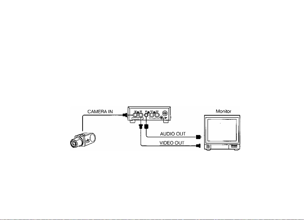
<Single Camera>
Camera Drive Unit
WV-PS11B
Camera
-5-
Page 8
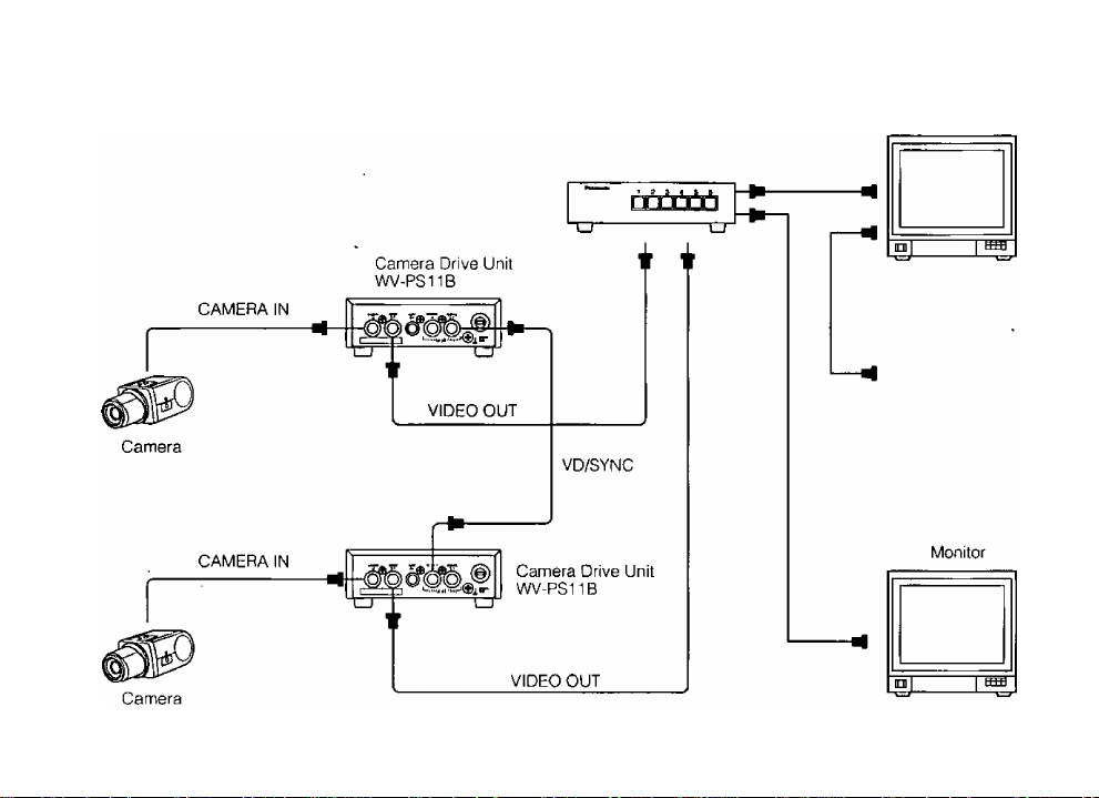
<Multi Camera System with External SYNC Operation>
Monitor
-6-
Page 9

Connect the coaxial cable between the camera
and CAMERA IN connector of the camera drive
unit. The approximate maximum cable length is as
follows:
Coaxial
Cable Type
RG-59/U
RG*6/U
DC R/1000 ft. of
Inner Conductor
Less than 30 ii
Less than 12 ii
Maximum
Cable Length
200 m (660 ft.)
500 m (1650 ft.)
The maximum DC resistance of the cable between
the camera and camera drive unit is 20 Ti.
Note:
If the length of the coaxial cable between the
camera drive unit and the video monitor
exceeds the distance shown in the above
table, a cable loss compensator should be
used between the camera drive unit and the
video monitor.
After connecting the specified camera to the cam
era drive unit, connect the audio cable between the
monitor and AUDIO OUT connector of the camera
drive unit.
2. Connect the coaxial cable between the video moni
tor and VIDEO OUT connector of the camera drive
unit. The approximate maximum cable length is as
follows:
Type of
coaxial cable
Recommended
RG-59/U
(3C-2V)
RG-6/U
(5C-2V)
(m) 250 500 600
RG-11/U
(7C-2V)
Maximum
cable length
825 1,650 1,980
(ft)
External VD/SYNC Signal
Signal Level
The VD/SYNC IN connector accepts the VD or VS syn
chronizing signal for external synchronization.
• VD: 4 V[p-p]/75 0
-7-
Page 10

Composite Sync: 4 V[p-p] /75
VS: 1 V[p-p] /75 Q
Accuracy of vertical signal
Vertical frequency: 59.940052 Hz± 0.00161 Hz
Relation between VD/SYNC IN and VD/SYNC OUT
The signal from the VD/SYNC OUT connector differs
according to the connected camera and the signal sup
plied to the VD/SYNC IN connector of this unit.
The signal supplied from VD/SYNC OUT is as follows:
'v Signal to
\VD/SYNC
Connected^
Camera
WV-BP70
or
WV-CP100
IN
No signal
Composite
signal'
VD signal
VD signal
Composite
signal
Composite
signal
-8-
Page 11

SPECIFICATIONS
Power Source:
Power Consumption:
Camera Input:
Video Output:
Audio Output:
Camera Power Supply:
Maximum Distance to Camera:
Maximum DC Resistance:
VD/SYNC Input:
VD/SYNC Output:
Ambient Operating Temperature:
Ambient Operating Humidity:
Dimensions:
Weight:
Weight and dimensions shown are approximate.
Specifications are subject to change without notice.
120 VAC 60 Hz
Approx. 16 W
1.0 V[p-p] / 75 a, BNC Connector
1.0 V[p-p] / 75 a, BNC Connector
-10 dB / 600 Q unbalanced, RCA pin jack
Regulated current multiplex method (310 mA)
Coaxial DC R/1000 ft. of Maximum
Cable Type Inner Conductor Cable Length
RG-59/U
RG-6/U
Between camera and camera drive unit: 20 iJ.
4.0 V[p'p] /75 a Negative going or VS 1 V[p-p] /75 a, BNC Connector
4.0 V[p-p] /75 a Negative going, BNC Connector
-10 X - +50 °C (14 °F - 122 °F)
Less than 90 %
138 (W)X44(H)X 185(D) mm
5-7/16" (W) X 1-3/4" (H) X 7-5/16" (D)
1.3 kg (2.9 lbs.)
Less than 30 n
Less than ^2íì
-9-
200 m (660 ft.)
500 m (1650 ft.
Page 12

Panasonic
Broadcast & Television Systems Company
Division ot Matsushita Electric Corporation o1 America
IMAGING SYSTEMS DIVISION
Executive Office: One Panasonic Way 3E-7, Secaucus, New Jersey 07094
Regional Offices:
Northeast; 43 Hartz Way, Secaucus, NJ 07094 (201) 348-7303
Southeast: 1225 Northbrook Parkway, Suite 1-160, Suwanee, GA 30174 (770) 338-6S35
Midwest: 1707 North Randall Road, Elgin. IL 60123 (847)468-5200
Southwest: 4500 Amon Carter Blvd., Fort Worth, TX 76155 (817) 685-1117
Western: 6550 Katella Ave. 17A-5, Cypress, CA 90630 (714) 373-7265
MATSUSHITA ELECTRIC OF CANADA LIMITED
5770 Ambler Drive, Mississauga, Ontario, U4W 2T3 Canada (905)624-5010
PANASONIC SALES COMPANY
DIVISION OF MATSUSHITA ELECTRIC OF PUERTO RICO, INC.
San Gabriel Industrial Park, 65th Infantry Ave, KM. 9.5 Carolina, Puerto Rico 00630 (809)750-4300
N1096-0
YWV8QA4372AN PrintBd in Japan
(N)30
 Loading...