

Page 1
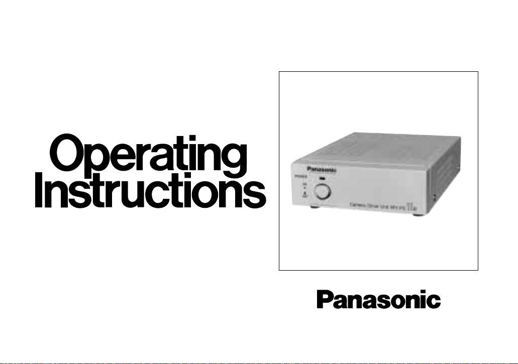
Camera Drive Unit
WV-PS11B
Before attempting to connect or operate this product,
please read these instructions completely.
Page 2
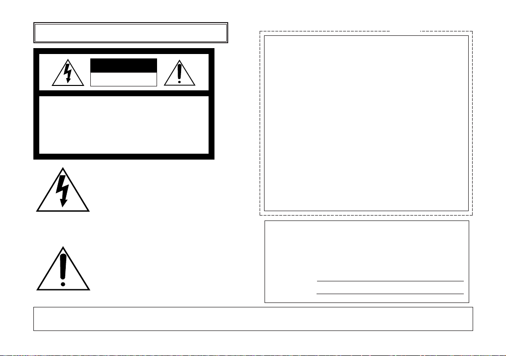
CAUTION
RISK OF ELECTRIC SHOCK
DO NOT OPEN
CAUTION:
TO REDUCE THE RISK OF ELECTRIC
SHOCK, DO NOT REMOVE COVER (OR
BACK), NO USER SERVICEABLE PARTS
INSIDE.
REFER SERVICING TO QUALIFIED SERVICE
PERSONNEL.
The serial number of this product may be found on the bottom of the unit.
You should note the serial number of this unit in the space
provided and retain this book as a permanent record of
your purchase to aid identification in the event of theft.
Model No.
Serial No.
The exclamation point within an equilateral triangle is intended to alert the user
to the presence of important operating
and maintenance (servicing) instructions in the literature accompanying the
appliance.
For U.K.
WARNING:
TO PREVENT FIRE OR ELECTRIC SHOCK HAZARD, DO NOT EXPOSE THIS APPLIANCE TO RAIN OR MOISTURE.
The lightning flash with arrowhead symbol, within an equilateral triangle, is
interned to alert the user to the presence of uninsulated "dangerous voltage" within the product's enclosure that
may be of sufficient magnitude to constitute a risk of electric shock to persons.
FOR YOUR SAFETY PLEASE READ THE FOLLOWING TEXT CAREFULLY.
This appliance is supplied with a moulded three pin mains plug for your
safety and convenience.
A 13 amp fuse is fitted in this plug.
Should the fuse need to be replaced please ensure that the replacement
fuse has a rating of 13 amp and that it is approved by ASTA or BSI to
BS1362.
Check for the ASTA mark
H or the BSI mark G on the body of the fuse.
If the plug contains a removable fuse cover you must ensure that it is refitted when the fuse is replaced.
If you lose the fuse cover the plug must not be used until a replacement
cover is obtained.
A replacement fuse cover can be purchased from your local Panasonic
Dealer.
IF THE FITTED MOULDED PLUG IS UNSUITABLE FOR THE SOCKET
OUTLET IN YOUR HOME THEN THE FUSE SHOULD BE REMOVED
AND THE PLUG CUT OFF AND DISPOSED OF SAFELY.
THERE IS A DANGER OF SEVERE ELECTRICAL SHOCK IF THE CUT
OFF PLUG IS INSERTED INTO ANY 13 AMP SOCKET.
If a new plug is to be fitted please observe the wiring code as shown
below.
If in any doubt please consult a qualified electrician.
WARNING: This apparatus must be earthed.
ENGLISH VERSION
Page 3
-1-
IMPORTANT
The wires in this mains lead are coloured in accordance with the following
code.
Green-and-yellow: Earth
Blue: Neutral
Brown: Live
As the colours of the wire in the mains lead of this appliance may not
correspond with the coloured markings identifying the terminals in your
plug, proceed as follows.
The wire which is coloured green-and-yellow must be connected to
the terminal in the plug which is marked with the letter E or by the earth
symbol
I or coloured green or green-and-yellow.
The wire which is coloured blue must be connected to the terminal in
the plug which is marked with the letter N or coloured black.
The wire which is coloured brown must be connected to the terminal
in the plug which is marked with the letter L or coloured red.
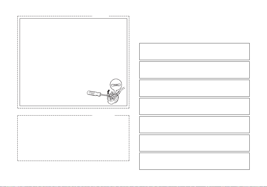
How to replace the fuse
Open the fuse compartment with
a screwdriver and replace the fuse
and fuse cover.
THIS APPARATUS MUST BE EARTHED.
To ensure safe operation the three-pin plug supplied must be inserted
only into a standard three-pin power point which is effectively earthed
through the normal household wiring. Extension cords used with the
equipment must be three-core and be correctly wired to provide connection to earth. Wrongly wired extension cords are a major cause of
fatalities.
The fact that the equipment operates satisfactorily does not imply that
the power point is earthed and that the installation is completely safe.
For your safety, if in any doubt about the effective earthing of the power
point, consult a qualified electrician.
For U.K.
For Australia
Wij verklaren als enige aansprakelijke, dat het product waarop
deze verklaring betrekking heeft, voldoet aan de volgende normen of andere normatiefve dokumenten, overeenkomstig de
bepalingen van Richtlijnen 73/23/EEC en 89/336/EEC.
Vi erklærer os eneansvarlige for, at dette produkt, som denne
deklaration omhandler, er i overensstemmelse med den
følgende standarder eller andre normative dokumenter i følge
bestemmelserne i direktivene 73/23/EEC og 89/336/EEC.
Vi deklarerar härmed värt fulla ansvar för att den produkt till
vilken denna deklaration hänvisar är i överensstämmelse med
standarddokument, eller andra normativa dokument som
framstölls i Direktiv 73/23/EEC och 89/336/EEC.
Ilmoitamme yksinomaisella vastuullamme, että tuote, jota tämä
ilmoitus koskee, noudattaa seuraavia standardeja tai muita
ohjeellisia asiakirjoja, jotka noudattavat direktiivien 73/23/EEC
ia 89/336/EEC. säädöksiä.
Vi erklærer oss alene ansvarlige for at produktet som denne
erklæringen gjelder for, er i overensstemmelse med følgende
normer eller andre normgivende dokumenter som fælger
bestemmelsene i direktiven 73/23/EEC og 89/336/EEC.
We declare under our sole responsibility that the product to
which this declaration relates is in conformity with the standards or other normative documents following the provisions of
Directives EEC/73/23 and EEC/89/336.
Noi dichiariamo sotto nostra esclusiva responsabilità che il
prodotto a cui si riferisce la presente dichiarazione risulta conforme ai seguenti standard o altri documenti normativi conformi
alle disposizioni delle direttive CEE/73/23 e CEE/89/336.
Caution:
Before attempting to connect or operate this product,
please read the label on the bottom.
Page 4

-2-
PREFACE
The Panasonic Camera Drive Unit WV-PS11B is specially designed to drive specified cameras such as WVBP70 or WV-CP100.
This simple system is specially designed for surveillance and security needs at offices, factories, schools,
hospitals, public or residential buildings, etc.
FEATURES
• Stable DC power is supplied to the specified camera by a regulator in the camera drive unit.
• A single coaxial cable connects the specified camera and camera input of the camera drive unit.
• Three signals, video, DC power and vertical drive
pulses, are carried by a single coaxial cable (used
with the WV-BP70 or WV-CP100 camera.).
• Audio signals can be transmitted from the specified camera to the camera drive unit (used with the
WV-CP100 or WV-CF20 camera.).
• VD/SYNC input and output connectors for synchronizing in the parallel operation.
• Built-in protection circuit protects the appliance in
case of wrong connection.
CONTENTS
PREFACE ..................................................................... 2
FEATURES ................................................................... 2
PRECAUTIONS ............................................................ 3
MAJOR OPERATING COMPONENTS
AND THEIR FUNCTIONS ............................................. 4
CONNECTIONS ........................................................... 5
SPECIFICATIONS ........................................................ 9
Page 5

-3-
PRECAUTIONS
• Do not block the ventilation opening or slots on the
cover to prevent the appliance temperature from
rising.
• Do not attempt to disassemble the appliance.
To prevent electric shock, do not remove screws or
covers. There are no user-serviceable parts inside.
• Handle the appliance with care.
Do not abuse the appliance. Avoid striking, shaking, etc. It could be damaged by improper handling or storage.
• Do not expose the appliance to rain or moisture.
Avoid trying to operate it in wet areas.
Take immediate action if ever the unit becomes
wet. Turn the power off and refer servicing to qualified service personnel. Moisture can damage the
appliance, and cause danger due to electric
shock.
• Do not use strong or abrasive detergents when
cleaning the appliance body.
Use a dry cloth to clean the unit when dirty. In case
the dirt is hard to remove, use a mild detergent and
wipe gently.
• Do not drop any metallic parts through slots.
This action could damage the appliance permanently. Turn the power off immediately and refer
servicing to qualified service personnel.
• Use the appliance under conditions where temperatures are within –10°C - +50°C (14°F - 122°F), and
humidity is below 90%. The input power source is
220 - 240V AC 50 Hz.
Do not operate the appliance in an extreme environment where is out of its specified temperature or
humidity range, or power source ratings.
Page 6

-4-
MAJOR OPERATING COMPONENTS AND THEIR FUNCTIONS
CAMERA
IN
VIDEO
OUT
AUDIO
OUT
VD/SYNC
IN
VD/SYNC
OUT
SIGNAL
GND
CAUTION
USE WITH SPECIFIED EQUIPMENT SEE
ITS MANUAL BEFORE CONECTING.
POWER
ON
OFF
q Power On/Off Switch (POWER, ON/OFF)
This switch is used to turn the camera drive unit
and connected specified camera power on or off.
The indicator lights up when the power of the camera drive unit is on.
w Camera Input Connector (CAMERA IN)
This connector accepts either a colour or B/W composite video signal from the specified camera. It
also supplies DC power and vertical drive pulses
or synchronizing signals to the camera, and
receives video and audio signal from the camera.
e Video Output Connector (VIDEO OUT)
The video signal of the specified camera is provided at this connector for input into the video monitor.
r Audio Output Connector (AUDIO OUT)
The audio signal of the specified camera is provided at this connector for input into the video monitor
(used with the WV-CF20 or WV-CP100 camera.).
t VD/SYNC Input Connector (VD/SYNC IN)
The VD (Vertical Drive) pulse or VS (Video Sync)
signal is supplied to this connector for synchronizing the system.
y VD/SYNC Output Connector (VD/SYNC OUT)
The VD (Vertical Drive) pulse or VS (Video Sync)
signal is provided at this connector for synchronizing other system component.
Page 7

-5-
CONNECTIONS
Cautions:
• Set the POWER switch of the camera drive unit to OFF (
l) during connections. If the power of the camera drive
unit is ON during connections, the protection circuit that protects it in case of wrong connection will operate and
prevent the camera from functioning.
• Connect only a specified camera, WV-BP70, WV-CF20 or WV-CP100. If another camera is connected, the camera drive unit will not operate due to activation of the protection circuit.
CAMERA
IN
VIDEO
OUT
AUDIO
OUT
VD/SYNC
IN
VD/SYNC
OUT
SIGNAL
GND
CAMERA IN
AUDIO OUT
Camera Drive Unit
WV-PS11B
VIDEO OUT
Monitor
Camera
<Single Camera>
Page 8

-6-
<Multi Camera System with External SYNC Operation>
CAMERA
IN
VIDEO
OUT
AUDIO
OUT
VD/SYNC
IN
VD/SYNC
OUT
SIGNAL
GND
CAMERA
IN
VIDEO
OUT
AUDIO
OUT
VD/SYNC
IN
VD/SYNC
OUT
SIGNAL
GND
654321
CAMERA IN
VD/SYNC
Camera Drive Unit
WV-PS11B
VIDEO OUT
Monitor
Camera
Camera
CAMERA IN
Camera Drive Unit
WV-PS11B
VIDEO OUT
Monitor
TL
VTR
Page 9

-7-
1. Connect the coaxial cable between the camera
and CAMERA IN connector of the camera drive
unit. The approximate maximum cable length is as
follows:
Coaxial DC R/1000 ft. of Maximum
Cable Type Inner Conductor Cable Length
RG-59/U Less than 30
Ω 200 m (660 ft.)
RG-6/U Less than 12 Ω 500 m (1,650 ft.)
The maximum DC resistance of the cable between
the camera and camera drive unit is 20 Ω.
2. Connect the coaxial cable between the video monitor and VIDEO OUT connector of the camera drive
unit. The approximate maximum cable length is as
follows:
Type of
coaxial cable
RG-59/U
(3C-2V)
RG-6/U
(5C-2V)
RG-11/U
(7C-2V)
Recommended
Maximum
cable length
(m)
(ft)
250
825
500
1,650
600
1,980
Note:
If the length of the coaxial cable between the
camera drive unit and the video monitor
exceeds the distance shown in the above
table, a cable loss compensator should be
used between the camera drive unit and the
video monitor.
3. After connecting the specified camera to the camera drive unit, connect the audio cable between the
monitor and AUDIO OUT connector of the camera
drive unit.
External VD/SYNC Signal
Signal Level
The VD/SYNC IN connector accepts the VD or VS synchronizing signal for external synchronization.
• VD: 4 V[p-p] / 75 Ω
Page 10

WV-BP70
or
WV-CP100
Signal to
VD/SYNC
IN
Connected
Camera
-8-
• Composite Sync: 4 V[p-p] /75 Ω
Composite
signal
VD signal
Composite
signal
No signal VD signal
Composite
signal
Relation between VD/SYNC IN and VD/SYNC
OUT
The signal from the VD/SYNC OUT connector differs
according to the connected camera and the signal supplied to the VD/SYNC IN connector of this unit.
The signal supplied from VD/SYNC OUT is as folllows:
Accuracy of vertical signal
Vertical frequency: 50 Hz ± 0.0013 Hz
• VS: 1 V[p-p] /75 Ω
Page 11

-9-
SPECIFICATIONS
Power Source: 220 - 240 V AC 50 Hz
Power Consumption: Approx. 16 W
Camera Input: 1.0 V[p-p] / 75 Ω, BNC Connector
Video Output: 1.0 V[p-p] / 75 Ω, BNC Connector
Audio Output: –10 dB / 600 Ω unbalanced, RCA pin jack
Camera Power Supply: Regulated current multiplex method (310 mA)
Maximum Distance to Camera:
Maximum DC Resistance: Between camera and camera drive unit: 20 Ω.
VD/SYNC Input: 4.0 V[p-p] /75 Ω Negative going or VS 1 V[p-p] /75 Ω, BNC Connector
VD/SYNC Output: 4.0 V[p-p] /75 Ω Negative going, BNC Connector
Ambient Operating Temperature: –10 °C – +50 °C (14 °F – 122 °F)
Ambient Operating Humidity: Less than 90 %
Dimensions: 138 (W) X 44 (H) X 185(D) mm
5-7/16” (W) X 1-3/4” (H) X 7-5/16” (D)
Weight: 1.3
kg (2.9 lbs.)
Weight and dimensions shown are approximate.
Specifications are subject to change without notice.
Coaxial DC R/1000 ft. of Maximum
Cable Type Inner Conductor Cable Length
RG-59/U Less than 30 Ω 200 m (660 ft.)
RG-6/U Less than 12 Ω 500 m (1,650 ft.)
Page 12

Matsushita Electric Industrial Co., Ltd.
Central P.O. Box 288, Osaka 530-91, Japan
N1096-0 YWV8QA4374AN Printed in Japan
N 19 Gedruckt in Japan
Imprimé au Japon
Impreso en Japón
 Loading...