

Panasonic WV-CW7S, WV-CW7SN Operating Instructions Manual
Operating Instructions
Included Installation Instructions
Dome Cover
Model No.
WV-CW7S / WV-CW7SN
ClearSight coating
(Rain wash coating)
FRANÇAIS DEUTSCH ENGLISHESPAÑOLITALIANO
please read these instructions carefully and save this manual for future use.
Before attempting to connect or install this product,
The model number is abbreviated in some descriptions in this manual.
РУССКИЙ
ENGLISH VERSION
Features
This product is the smoked dome cover.
WV-CW7SN is applied with rain wash coating.
Precautions
Refer installation work to the dealer.
Installation work requires technique and experiences. Failure to observe this may cause fi re, electric
shock, injury, or damage to the product.
Be sure to consult the dealer.
Installations
The following are installation instructions using WV-S2531LN as a representative example. Refer to
manuals of each model upon installation.
Note:
• When the smoke type dome cover is used, the reach distance of IR will become shorter and
the ambient illuminance for the day & night switchover will become lower compared to the
standard clear type dome cover. Please reconfirm the performance after reinstalling the enclosure to the camera.
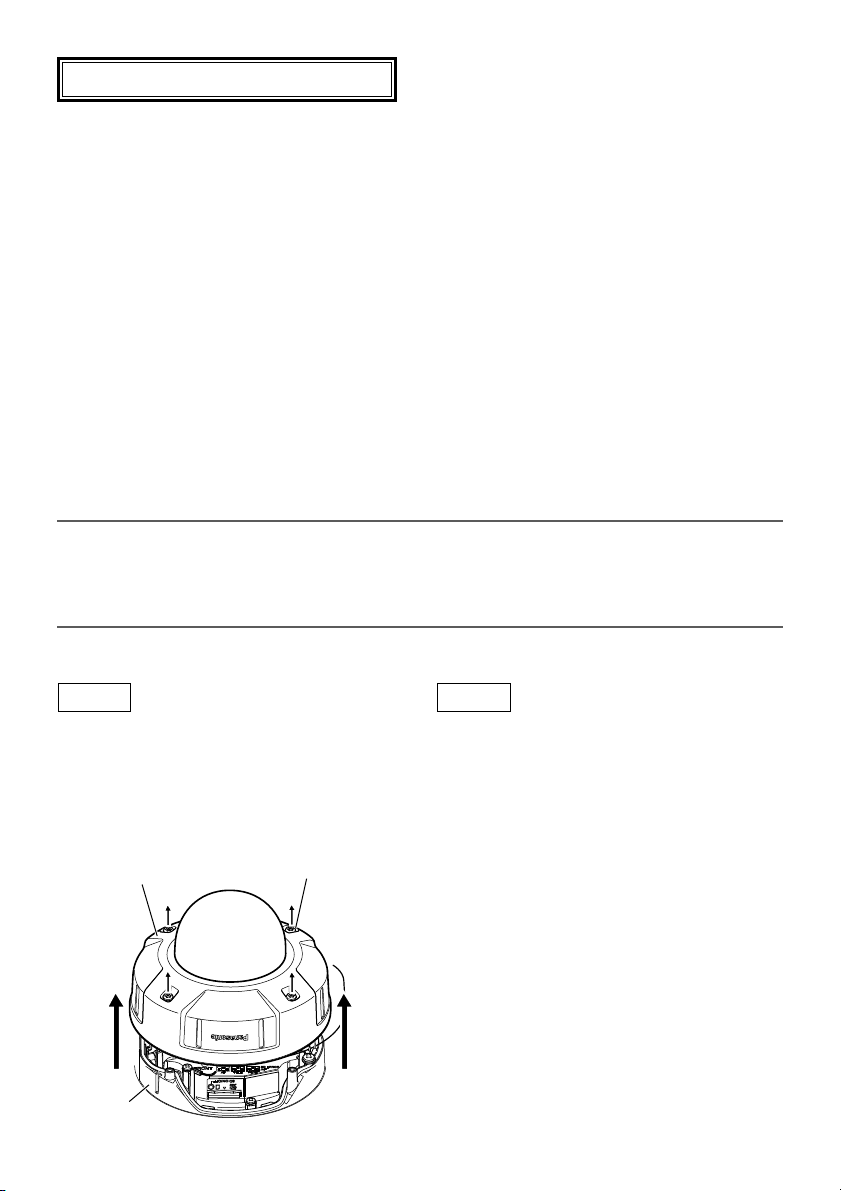
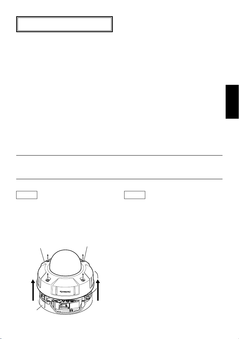
Step 1
Remove the enclosure from the camera
body
Loosen the 4 enclosure fixing screws using the
bit provided with
the enclosure from the camera
Enclosure
Camera
body
the camera, and then remove
body.
Enclosure fixing
screws (4 pcs.)
2
Step 2
Remove the dome cover
Remove the 3 dome cover fixing screws (2 without washers, 1 with washer), and then remove
the dome cover holding plate, the light-blocking
sheet (WV-SFV631LT/ WV-SFV631L/
WV-SFV611L only), the dome cover and the
waterproof rubber from the enclosure.
(The Dome cover holding plate and the camera
body are connected with the installation auxiliary
wire. Please pay attention that the installation
auxiliary wire will be removed at the moment
when the dome cover fixing screws are
removed.)
Keep the removed dome cover holding plate,
light-blocking sheet (WV-SFV631LT/
the
WV-SFV631L/ WV-SFV611L only)
screws until using them in step 3.
, 3 fixing
Step 3
Replace the dome cover
AAttach the waterproof rubber provided with
the new dome cover to the enclosure. Make
sure that the waterproof rubber is attached
without distortion or deformation. Do not
use the waterproof rubber removed from the
enclosure. Use the new waterproof rubber
provided with the new dome cover.
BRemove the protection film covering outside
the new dome cover.
Keep the removed protection film until using
it upon the installation.
(Handle the new dome cover with care not
to scratch inside and outside.)
CFit the new dome cover, the light-blocking
sheet (WV-SFV631LT/ WV-SFV631L/
WV-SFV611L only) and the dome cover holding plate together while aligning the holes
on them to the 2 protrusions inside the
enclosure, and then fix them using the 2
dome cover fixing screws (without washers).
(Recommended tightening torque:
0.78 N·m {
DAttach the protection film removed in
step3-B back to the outside the dome
cover.
0.58 lbf·ft})
Step 4
Fit the enclosure back to the camera body
Fix the enclosure onto the camera body using
the 4 enclosure fixing screws.
The recommended tightening torque for the
enclosure fixing screws is 0.78 N·m {
0.58lbf·ft}.
⇒ Refer to the Installation Guide of the camera
for the subsequent procedures including the
installation of the camera
IMPORTANT:
• Defocus may be caused by the reinstalled
enclosure. After installing the enclosure,
activate the auto focus function from the
setup menu.
• Remove the protection film covering the
outside of the dome cover after completing
the installation.
• Wipe out with a soft cloth when cleaning
adhesion of dirt such as a fingerprint.
(WV-CW7S only)
• Refer to "Precautions"(leaflet) and clean
the dome cover. (WV-CW7SN only)
body.
ENGLISH
EWhen fixing the third dome cover fixing
screw (with washer), fix the installation auxiliary wire together
When fixing with the screw, make sure that
the flat face of the fixing terminal is the surface side of the dome cover holding plate.
Make also sure that the fixing terminal is not
on the projection of the dome cover holding
plate. (Refer to the diagram below.)
(Recommended tightening torque:
0.78 N·m {
.
0.58 lbf·ft})
3
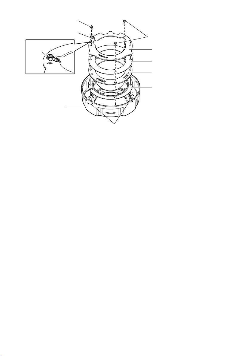
Fixing screw (with washer, 1 pc.)
Installation auxiliary wire
Washer
Enclosure
Protrusion
Fixing screw
(without washer, 2 pcs.)
Dome cover holding plate
Light-blocking sheet (WV-SFV631LT/
WV-SFV631L/ WV-SFV611L only)
Dome cover (smoke)
Waterproof rubber
Specifications
Ambient operating temperature: –45 °C to +60 °C {–49 °F to 140 °F}
Mass: Approx. 74 g {
Dimensions: Diameter: 115 mm {4-17/32 inches}
Height: 60 mm {2-3/8 inches}
Dome radius 42 mm {1-21/32 inches}
0.16 lbs}
Standard Accessories
Operating Instructions (this document) .............1 set
Precautions (leaflet) ..........................................1 pc
Waterproof rubber (for replacement) ................1 pc.
4
DEUTSCHE AUSGABE
(GERMAN VERSION)
Merkmale
Dieses Produkt stellt die Rauchglas-Glockenabdeckung dar.
Die WV-CW7SN wird mit wasserabstoßender Beschichtung eingesetzt.
Vorsichtsmaßregeln
Zur Installation an einen Fachhändler wenden.
Installationsarbeiten erfordern Fachkenntnisse und Erfahrung. Andernfalls besteht die Gefahr von
Brand, elektrischem Schlag, Verletzungen oder Schäden an diesem Produkt.
Unbedingt einen Fachhändler konsultieren.
Installation
Im Folgenden wird das Installationsverfahren anhand des Modells WV-S2531LN beschrieben. Bei
der Installation auf das Handbuch des jeweiligen Modells beziehen.
Anmerkung:
• Bei Verwendung der Rauchglas-Glocke verkürzt sich die IR-Reichweite und die Beleuchtungsstärke im Umfeld für die Tag/Nacht-Umschaltung wird schwächer im Vergleich zur KlarsichtGlocke.
Die Funktion der Kamera nach dem Einbau in das Gehäuse nochmals überprüfen.
DEUTSCH
Schritt 1
Das Gehäuse von der Kamerakörper
abnehmen
Die 4 Gehäuse-Befestigungsschrauben mit
dem der Kamera beiliegenden Einsatz lösen
und anschließend das Gehäuse vom Kamerakörper trennen.
Gehäuse-Befestigungs-
Gehäuse
Kamerakörper
schrauben (4 St.)
Schritt 2
Entfernen der Glockenabdeckung
Die 3 Befestigungsschrauben der Glockenabdeckung (2 ohne und 1 mit Unterlegscheibe)
herausdrehen und die Halteplatte, den
ckierenden Ring (nur WV-SFV631LT/
WV-SFV631L/ WV-SFV611L)
Glockenabdeckung und den wasserdichten
Gummiring vom Gehäuse abnehmen.
(Die Halteplatte der Glockenabdeckung und
der Kamerakörper sind durch einen Fangdraht
verbunden. Dieser Fangdraht muss beim
Herausdrehen der Befestigungsschrauben der
Glockenabdeckung ebenfalls gelöst werden.)
Die Halteplatte der Glockenabdeckung, den
lichtblockierenden Ring (nur WV-SFV631LT/
WV-SFV631L/ WV-SFV611L)
Befestigungs schrauben zur Wiederverwendung
in Schritt 3 aufbewahren.
, die
und die 3
lichtblo-
5

Schritt 3
Anbringen der Glockenabdeckung
ADen der neuen Glockenabdeckung beilie-
genden wasserdichten Gummiring am
Gehäuse anbringen. Darauf achten, den
wasserdichten Gummiring beim Einbau nicht
zu verdrehen oder verformen. Der alte wasserdichte Gummiring, der vom Gehäuse entfernt wurde, darf nicht wiederverwendet
werden. Den der neuen Glockenabdeckung
beiliegenden wasserdichten Gummiring verwenden.
BDie Schutzfolie von der neuen Glockenab-
deckung abziehen.
Die abgezogene Schutzfolie für die Wieder-
verwendung aufbewahren.
(Die neue Glockenabdeckung vorsichtig
behandeln, damit sie weder innen noch
außen verkratzt wird.)
CDie neue Glockenabdeckung, den
ckierenden Ring (nur WV-SFV631LT/
WV-SFV631L/ WV-SFV611L)
Halteplatte zusammenfügen, die darin
befindlichen Löcher auf 2 der Haltenasen im
Inneren des Gehäuses ausrichten und die
Teile dann mit 2 der Befestigungsschrauben
(ohne Unterlegscheiben) verschrauben.
(Empfohlenes Anzugsmoment: 0,78 N·m)
lichtblo-
und die
Schritt 4
Das Gehäuse wieder am Kamerakörper
anbringen
Das Gehäuse mit den 4 Gehäuse-Befestigungsschrauben am Kamerakörper befestigen.
Für die Gehäuse-Befestigungsschrauben wird
ein Anzugsmoment von 0,78 N·m empfohlen.
⇒ Die anschließenden Schritte einschließlich
der Installation des
Installationshandbuch der Kamera beschrieben.
WICHTIG:
• Durch das Wiederanbringen des Gehäuses
kann die Fokuseinstellung gestört werden.
Nach Anbringen des Gehäuses die FokusAutomatik über das Setupmenü aktivieren.
• Nachdem die Installation beendet ist, die
Schutzfolie von der Außenfläche der
Glockenabdeckung entfernen.
• Anhaftenden Schmutz oder
Fingerabdrücke mit einem weichen Lappen
abwischen. (nur WV-CW7S)
• Zum Reinigen der Glockenabdeckung
siehe “Vorsichtsmaßregeln” (Broschüre).
(nur WV-CW7SN)
Kamerakörpers sind im
DDie in Schritt 3 - B abgezogene Schutzfolie
wieder außen an der Glockenabdeckung
anbringen.
EBeim Einschrauben der dritten Befesti-
gungsschraube der Glockenabdeckung (mit
Unterlegscheibe) den Fangdraht mit der
Schraube sichern.
Dabei darauf achten, dass die Öse am
Fangdraht mit der flachen Seite auf dem
Halteplatte aufliegt. Sicherstellen, das die
Öse am Fangdraht nicht auf einem
Vorsprung der Halteplatte aufliegt. (Siehe
die folgende Abbildung.)
(Empfohlenes Anzugsmoment: 0,78 N·m)
6
 Loading...