

Panasonic WV-CW634S, WV-CW634F Installation Manual
Installation Guide
Color CCTV Camera
Model No. WV-CW634S
WV-CW634F
WV-CW634S
WV-CW634F
For information about how to perform the settings and how to operate the
camera, refer to the Operating Instructions on the provided CD-ROM.
Before attempting to connect or operate this product, please read these
instructions carefully and save this manual for future use.
The model number is abbreviated in some descriptions in this manual.
WARNING:
• This apparatus must be earthed.
• Appara tus shall be connected to a mains
socket outlet with a protective earthing connection.
• The mains plug or an appliance coupler shall
remain readily operable.
• All work related to the installation of this product should be made by qualified service personnel or system installers.
• The connections should comply with local
electrical code.
• To prevent inj ury, this apparatus must be
securely attached to the floor/wall/ceiling in
accordance with the installation instructions.
CAUTION
RISK OF ELECTRIC
SHOCK DO NOT OPEN
CAUTION: TO REDUCE THE RISK OF ELECTRIC SHOCK,
DO NOT REMOVE COVER (OR BACK).
NO USER-SERVICEABLE PARTS INSIDE.
REFER SERVICING TO QUALIFIED SERVICE PERSONNEL.
The lightning flash with arrowhead symbol, within an equilateral triangle, is intended to alert
the user to the presence of
uninsulated "dangerous voltage" within the product's enclosure that may be of sufficient
magnitude to constitute a risk of
electric shock to persons.
The exclamation point within an
equilateral triangle is intended
to alert the user to the presence
of important operating and
maintenance (servicing) instructions in the literature accompanying the appliance.
CAUTION:
• An ALL-POLE MAINS SWITCH with a contact
separation of at least 3 mm in each pole shall
be incorporated in the electrical installation of
the building.
• Any changes or modifications not expressly
approved by the party responsible for compliance could void the user’s authority to operate
the equipment.
For Canada
CAN ICES-3(A)/NMB-3(A)
For U.S.A.
NOTE: Thi s equi pme nt has been tested and
found to comply with the limits for a Class A digital device, pursuant to Part 15 of the FCC Rules.
These limits are designed to provide reasonable
protection against harmful interference when the
equipment is operated in a commercial environment. This equipment generates, uses, and can
ra di at e ra dio freq ue nc y energy and , if not
in st al le d an d us ed in accorda nc e wi th the
instruction manual, may cause harmful interference to radio communications.
Operation of this equipment in a residential area
is likely to cause harmful interference in which
case the user will be required to correct the interference at his own expense.
FCC Caution: To assure continued compliance,
(example - use only shielded interface cables
when connecti ng to co mputer or periph eral
devic es). Any change s or mod ifica tions not
expressly approved by the party responsible for
compliance could void the user’s authority to
operate this equipment.
For U.S.A.
The model number and serial number of this
product may be found on the surface of the
unit.
You should note the model number and serial
number of this unit in the space provided and
retain this book as a permanent record of your
purchase to aid identification in the event of
theft.
Model No.
Serial No.
2

Important safety instructions
1) Read these instructions.
2) Keep these instructions.
3) Heed all warnings.
4) Follow all instructions.
5) Do not block any ventilation openings. Install in accordance with the manufacturer's instructions.
6) Do not install near any heat sources such as radiators, heat registers, stoves, or other apparatus (including amplifiers) that produce heat.
7) Protect the power cord from being walked on or pinched particularly at plugs, convenience
receptacles, and the point where they exit from the apparatus.
8) Only use attachments/accessories specified by the manufacturer.
9) Use only with the cart, stand, tripod, bracket, or table specified by the manufacturer, or sold
with the apparatus. When a cart is used, use caution when moving the cart/apparatus combination to avoid injury from tip-over.
S3125A
10) Unplug this apparatus during lightning storms or when unused for long periods of time.
11) Refer all servicing to qualified service personnel. Servicing is required when the apparatus has
been damaged in any way, such as power-supply cord or plug is damaged, liquid has been
spilled or objects have fallen into the apparatus, the apparatus has been exposed to rain or
moisture, does not operate normally, or has been dropped.
3

Limitation of liability
THIS PUBLICATION IS PROVIDED "AS IS" WITHOUT WARRANTY OF ANY KIND, EITHER
EXPRESS OR IMPLIED, INCLUDING BUT NOT LIMITED TO, THE IMPLIED WARRANTIES OF
MERCHANTABILITY, FITNESS FOR ANY PARTICULAR PURPOSE, OR NON-INFRINGEMENT OF
THE THIRD PARTY’S RIGHT.
THIS PUBLICATION COULD INCLUDE TECHNICAL INACCURACIES OR TYPOGRAPHICAL
ERRORS.
CHANGES ARE ADDED TO THE INFORMATION HEREIN, AT ANY TIME, FOR THE IMPROVEMENTS OF THIS PUBLICATION AND/OR THE CORRESPONDING PRODUCT (S).
Disclaimer of warranty
IN NO EVENT SHALL Panasonic System Networks Co., Ltd. BE LIABLE TO ANY PARTY OR ANY
PERSON, EXCEPT FOR REPLACEMENT OR REASONABLE MAINTENANCE OF THE PRODUCT,
FOR THE CASES, INCLUDING BUT NOT LIMITED TO BELOW:
(1) ANY LOSS OR DAMAGE, INCLUDING WITHOUT LIMITATION, DIRECT OR INDIRECT, SPE-
CIAL, CONSEQUENTIAL OR EXEMPLARY, ARISING OUT OF OR RELATING TO THE PRODUCT;
(2) ANY INCONVENIENCE, LOSS, OR DAMAGE CAUSED BY INAPPROPRIATE USE OR NEGLI-
GENT OPERATION OF THE USER;
(3) ALL MALFUNCTIONS OR TROUBLES FROM UNAUTHORIZED DISASSEMBLE, REPAIR OR
MODIFICATION OF THE PRODUCT BY THE USER, REGARDLESS OF THE CAUSE OF THE
MALFUNCTION OR TROUBLE;
(4) INCONVENIENCE OR ANY LOSS ARISING WHEN IMAGES ARE NOT DISPLAYED, DUE TO
ANY REASON OR CAUSE INCLUDING ANY FAILURE OR PROBLEM OF THE PRODUCT;
(5) ANY PROBLEM, CONSEQUENTIAL INCONVENIENCE, OR LOSS OR DAMAGE, ARISING
OUT OF THE SYSTEM COMBINED BY THE DEVICES OF THIRD PARTY;
(6) ANY CLAIM OR ACTION FOR DAMAGES, BROUGHT BY ANY PERSON OR ORGANIZATION
BEING A PHOTOGENIC SUBJECT, DUE TO VIOLATION OF PRIVACY WITH THE RESULT OF
THAT SURVEILLANCE-CAMERA'S PICTURE, INCLUDING SAVED DATA, FOR SOME REASON, BECOMES PUBLIC OR IS USED FOR ANY PURPOSE;
(7) LOSS OF REGISTERED DATA CAUSED BY ANY FAILURE.
4

Contents
Important safety instructions ......................................................................................................... 3
Limitation of liability ....................................................................................................................... 4
Disclaimer of warranty ................................................................................................................... 4
Preface .......................................................................................................................................... 6
Features ......................................................................................................................................... 6
About the user manuals ................................................................................................................7
Trademarks and registered trademarks......................................................................................... 7
Precautions ................................................................................................................................... 8
Precautions for Installation .......................................................................................................... 10
Major operating controls and their functions .............................................................................. 12
Preparations ................................................................................................................................ 14
Make a connection ...................................................................................................................... 19
Camera installation ...................................................................................................................... 23
Setup menu ................................................................................................................................. 32
Basic operation ...........................................................................................................................33
Troubleshooting ........................................................................................................................... 36
Specifications .............................................................................................................................. 37
Standard accessories .................................................................................................................. 39
Optional Accessories .................................................................................................................. 40
5

Preface
This product is a 1/3-inch type {1/3"} CCD color CCTV camera. Connection of this product to a
video monitor allows users to use this product as a monitoring camera.
Features
Super Dynamic 6
For photographic subjects which contain high contrast between the bright and dark areas, light
compensation on the pixel level will result in more natural-looking images.
Introduction of newly developed high-resolution CCD
The introduction of the newly developed CCD with 976 of horizontal pixels has led to the horizontal
resolution of as high as 700 TV lines (typ.).
Auto back focus (ABF) function equipped
Moving the CCD inside the camera to an optimal position with the operation button of this unit or
the setup menu allows users to automatically adjust the back focus.
The back focus is adjustable with the setup menu through the system controller (option) even after
installation of this unit.
The auto back focus function also allows users to correct out of focus when changing between
color and black-and-white images.
High sensitivity achieved thanks to noise reduction function
The introduction of low noise circuit design has achieved excellently high sensitivity resulting in the
minimum illuminance of 0.08 lx in the color mode and 0.008 lx in the black-and-white mode.
Night monochrome image activation function equipped
No operation is required at night because the image automatically changes from the color mode to
the black-and-white mode at low illuminance.
Motion detection function (VMD) equipped
The motion of an object is detectable. The acts of covering the camera with a cloth, a cap or other
acts and changing the camera direction during surveillance can be detected.
6

Note:
• The VMD function is not the dedicated function to prevent thefts, fires, etc. We are not responsible for any accidents or damages caused by applying the function for the above purposes.
Optional heater unit can be connected
When using the optional heater unit, the product can be used at temperatures within –30 °C to
+60°C {–22 °F to +140 °F} and humidity within 10 % to 90 %.
The camera conforms to the IP66
performance.
Waterproofing treatment is not required for the camera body (waterproofing treatment is required
for cable connections).
*1 IP66 rating: The applicable product has "Dust tight (6)" protection against foreign solids and has
"Powerful water jets (6)" against water (IEC60529).
*1
and provides high dust resistance and waterproof
About the user manuals
The operating instructions of the camera consist of 2 sets: this book and operating instructions
(PDF).
This book explains how to install the camera.
Refer to the "Operating Instructions (PDF)" on the provided CD-ROM for descriptions of how to perform
the unit settings. Adobe
on the PC, download the latest Adobe
®
Reader® is required to read PDF. When the Adobe® Reader® is not installed
®
Reader® from the Adobe web site and install it.
Trademarks and registered trademarks
Adobe, Acrobat Reader and Reader are either registered trademarks or trademarks of Adobe Systems Incorporated in the United States and/or other countries.
7

Precautions
The following points as well as the contents of "Warning" and "Caution" shall be
observed.
Refer installation work to the dealer.
Installation work requires technique and experiences. Otherwise injury, or damage to the
product may result.
Be sure to consult the dealer.
Do not insert objects inside the product.
If water or metallic items enter the product, it
may cause fire or electric shock.
Turn the power off immediately and contact
qualified service personnel for service.
Do not attempt to disassemble or modify
the product.
Failure to observe this may cause fire or electric
shock.
Consult the dealer for the repair or inspections.
Stop operation immediately when something is wrong with the product.
When smoke goes up from the product or the
smell of smoke comes from the product, continued use will result in fire, injury, or damage to
the product.
Turn the power off immediately and contact
qualified service personnel for service.
Select an installation area that can support the total weight.
Selecting an inappropriate installation surface
may cause the product to fall down or topple
over, resulting in injury.
Installation work shall be started after sufficient
reinforcement.
Periodic inspections shall be conducted.
Rust on the metal parts or screws may cause
the product to fall down resulting in injury.
Consult the dealer for the inspections.
This product shall be installed in a vibration-free place.
Failure to observe this may cause screws and
bolts to be loosened and consequently to fall
resulting in injury.
Install this product in a location high
enough to avoid people and objects from
bumping the product.
Failure to observe this may cause a drop resulting in injury or accidents.
Do not strike or give a strong shock to this
product.
Failure to observe this may cause injury or fire.
Turn the power off when do wiring of this
product.
Failure to observe this may cause electric
shock. A short circuit or wrong wiring may
cause fire.
Do not use the product in an atmosphere
of flammable gases.
Failure to observe this may cause injury by
explosion.
Avoid installing the product in locations
where it is subject to damage by salt or
corrosive gas.
Otherwise the mounting fixtures will deteriorate,
causing the product to fall down and leading to
accidents.
Use the specified mount bracket.
Failure to observe this may cause a drop resulting in injury or accidents.
Do not rub the edges of metal parts with
your hand.
Failure to observe this may cause injury.
Tighten screws and mounting fixtures to
the specified torque.
Failure to observe this may cause a drop resulting in injury or accidents.
8

[Precautions for use]
Blight subject
This product has no power switch.
Turn the power off when cleaning the product.
To keep on using with stable performance
Parts of this product may deteriorate and it
may shorten the lifetime of this product when
using in locations subject to high temperatures
and high humidity.
Do not expose this product to direct heat
sources such as a heater.
Handle this product with care.
Do not abuse this product. Avoid striking, shaking, etc. The product could be damaged by
improper handling or storage. If a strong shock
or vibration is applied to the enclosure, it may
cause damage or allow water to enter this
product.
Cleaning this product body
Turn the power off when cleaning the product.
Do not use strong abrasive detergent when
cleaning this product. Otherwise, it may cause
discoloration. When using a chemical cloth for
cleaning, read the caution provided with the
chemical cloth product.
To remove stubborn stains
When the dirt is hard to remove, use a mild
detergent and wipe gently. Then, wipe off the
remaining detergent with a dry cloth.
What to do if "OVER HEAT" appears on the
display
This message indicates that the inside of the
camera has become extremely hot. Immediately turn off the power of the camera and contact
your dealer.
Do not touch the dome cover with your
bare hands.
A dirty dome cover causes deterioration of picture quality.
Discoloration on the CCD color filter
When continuously shooting a bright light
source such as a spotlight, the color filter of the
CCD may have deteriorated and it may cause
discoloration. Even when changing the fixed
shooting direction after continuously shooting a
spotlight for a certain period, the discoloration
may remain.
Do not aim this product at strong light
sources.
A light source such as a spot light causes a
blooming (light bleeding) or a smear (vertical
lines).
Smear
Blooming
What to do if "WARMING UP-PLEASE
WAIT" appears on the display
*
This message indicates that the temperature
inside the camera has become extremely low.
In such a case, wait until the heater unit (option)
raises the internal temperature (for around
2 hours or more in low temperatures below
–10 °C {+14 °F}), and turn on the power again.
* To ensure this function works normally, the
heater unit (option) is required.
What to do if "CAMERA TEMP. TOO COLD.
POWER ON AT –30 DEG C (–22 DEG F) OR
MORE." appears on the display
The ambient temperature is too cold.
Please turn on the power under the conditions
where the ambient temperature is above
–30 °C {–22 °F}.
9

Precautions for Installation
The following points as well as the contents of "Warning" and "Caution" shall be observed.
Panasonic assumes no responsibility for
injuries or property damage resulting from
failures arising out of improper installation
or operation inconsistent with this documentation.
Installation work shall be performed in
accordance with the technology standard
of the electric installation.
Keep the product out of direct sunlight.
When the product is installed in areas that receive
direct sunlight, such as on external walls, use the
optional "Sun Shade WV-Q7118*".
* In order to attach WV-Q7118 to WV-CW634F,
WV-Q115A is required.
Installing place
Contact your dealer for assistance if you are
unsure of an appropriate place in your particular environment.
• Make sure that the installation area is
strong enough to hold the product, such
as a concrete ceiling.
• Install the camera in the foundation area of
the architecture or where sufficient strength
is assured.
• If a ceiling board such as plaster board is
too weak to support the total weight, the
area shall be sufficiently reinforced.
Avoid installing this product in the following locations.
• Locations where a chemical agent is used
such as a swimming pool.
• Locations subject to steam and oil smoke
such as a kitchen, Locations near flammable gas or vapor.
• Locations where radiation or x-ray emissions are produced.
• Locations where corrosive gas is produced, Locations where it may be damaged by briny air such as seashores.
• Locations where the temperature is not within –10 °C to +60 °C {+14 °F to +140 °F}.
(When using the optional heater unit, the
product can be used at temperatures within
–30 °C to +60 °C {–22 °F to +140 °F} and
humidity below 90 %.)
• Locations subject to vibrations (This product is not designed for on-vehicle use.)
Avoid moist or dusty places to install this
system.
Otherwise, lifetime of the internal parts may be
shortened.
Avoid installing the camera in a place with
a high level of noise.
Installation near an air conditioner, an air cleaner, a vending machine, or the like causes noise.
Be sure to remove this product if it is not
in use.
Keep the camera cable away from the
lighting cable.
Failure to observe this may cause noise.
Radio interference
When the camera is used near TV/radio antenna, strong electric field or magnetic field (near a
motor or a transformer), images may be distorted and noise sound may be produced.
In such a case, run the camera cable through
specialized steel conduit tubes.
Locally procure the screws
Screws are not supplied with this product. Prepare the screws according to the material,
structure, strength and other factors of the
mounting area and the total weight of objects
to be mounted.
10
Mounting screws
• The screws and bolts must be tightened
with an appropriate tightening torque
according to the material and strength of
the installation area.
• Do not use an impact driver. Failure to
observe this may cause overtightening and
consequently damage to the screws.
• When a screw is tightened, make the
screw at a right angle to the surface. After
tightening the screws or bolts, perform
visual check to ensure tightening is enough
and there is no backlash.
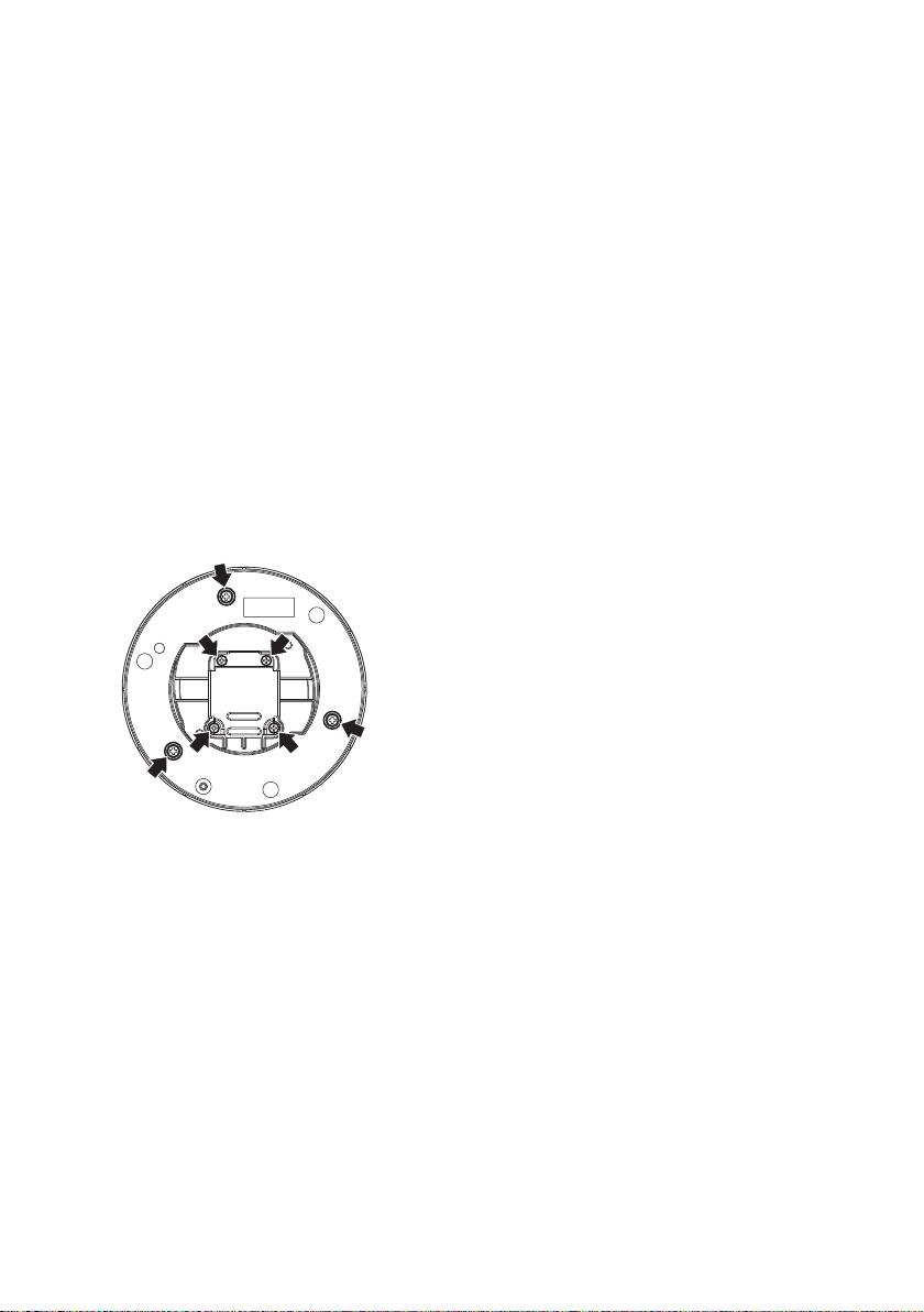
Do not remove or loosen the screws.
Do not remove or even loosen the screws (7
pieces) on the rear of the camera.
Otherwise, water exposure may cause damage
or malfunction of camera, or camera dropping
may result in injury.
11
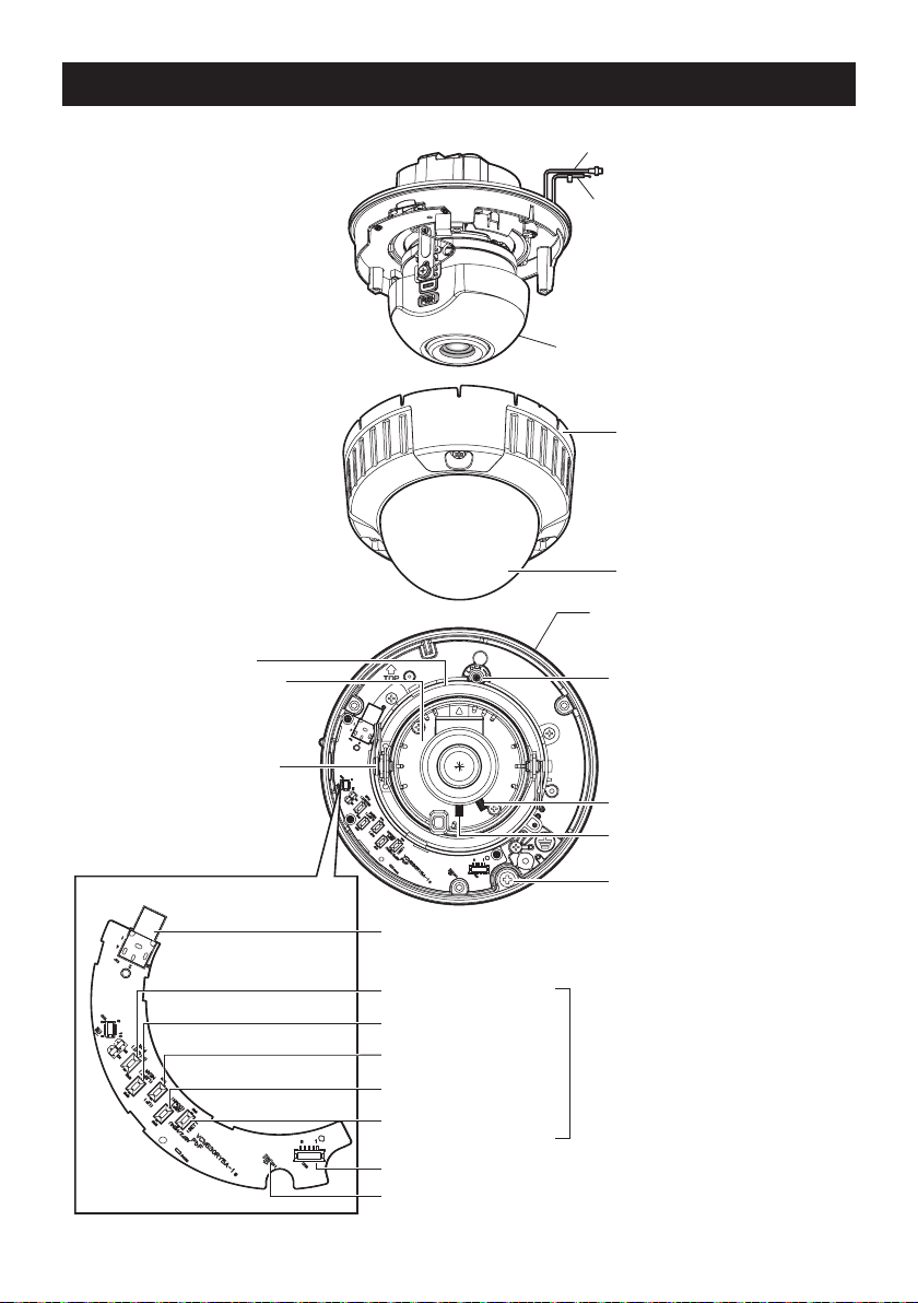
Major operating controls and their functions
Video output cable
w
q Power cord
!9 Inner dome
* This illustration shows the camera
r Panning table
t Tilt adjusting table
e Enclosure
@0 Dome
without the inner dome.
u Panning lock screw
12
Tilting lock screw
y
!1 Monitor output connector
!2 Right button
[(RIGHT), FAR]
!3 Left button
[(LEFT), NEAR]
!4 Up button
[(UP)]
!5 Down button
[(DOWN), ABF1]
!6 Setting button
[(SET), ABF2/MENU]
!7 Heater output connector
ABF operation indicator
!8
i Focus lock knob
o Zoom lock knob
!0 Camera xing screw
Operation
buttons

q Power cord
w Video output cable
e Enclosure
r Panning table
Rotate this table to adjust the panning
angle of the camera.
t Tilt adjusting table
Adjust the azimuth angle of the image.
y Tilting lock screw
Locks the tilt position.
u Panning lock screw
Fixes the panning table.
i Focus lock knob
Locks the focal point.
o Zoom lock knob
Locks the zoom point.
!0 Camera fixing screw
Fix the attachment on the camera body.
!5 Down button [(DOWN), ABF1]
Moves the cursor downward and selects
items in the setup menu. Refer to page 29
for further information about [ABF1].
(Pressing and holding for 3 s, image upside-
down)
!6 Setting button [(SET), ABF2/MENU]
Confirms the setting contents. Refer to page 31
for further information about [ABF2].
!7 Heater output connector
The cable of heater unit (option) is connected
to this connector. (+ page 22)
!8 ABF operation indicator
Indicates the status of ABF operation.
!9 Inner dome
@0 Dome
!1 Monitor output connector
Connect the monitor for adjustment to this
output connector.
!2 Right button [(RIGHT), FAR]
Moves the cursor to the right, selects the
mode and adjusts some levels.
!3 Left button [(LEFT), NEAR]
Moves the cursor to the left, selects the
mode and adjusts some levels.
!4 Up button [(UP)]
Moves the cursor upward and selects
items in the setup menu.
(Pressing and holding for 3 s, SD6 ON/OFF)
13

Preparations
When installing the camera on a wall or a ceiling, there are two methods as specified below.
(+ Next page)
• Using a two-gang junction box (locally procured)
• WV-CW634S: Using the mounting base (accessory)
WV-CW634F: Using the mounting base WV-Q115A (option)
Refer to all work related to the installation of this product to qualified service personnel or system
installer.
• The mounting base WV-Q115A is optional for WV-CW634F. Use the screws supplied with the
camera mount bracket.
Important:
• Prepare the mounting screw according to the material of the area where the attachment plate
(accessory) is to be installed. In this case, wood screws and nails should not be used. For
mounting a camera on a concrete ceiling, use an anchor bolt (M4) or an AY plug bolt (M4) for
securing.
(Recommended tightening torque M4: 1.6 N·m {1.18 lbf·ft})
• Required pull-out capacity of a single screw/bolt is 196 N {44.06 lbf} or more.
• If a ceiling board such as plaster board is too weak to support the total weight, the area shall
be sufficiently reinforced.
• When using an optional mount bracket, refer to the operating instructions of the bracket in use.
The mounting conditions of the camera mount bracket are described as follows:
Installation
place
Ceiling/wall Two-gang junction box
Ceiling/wall WV-Q115A or mounting
Ceiling/wall Optional mount brackets
Applicable mount
bracket
(locally procured)
base (accessory)
(Refer to page 40)
Recommended
screw
M4 or equivalent 4 pcs. 196 N {44.06 lbf}
M4 or equivalent 4 pcs. 196 N {44.06 lbf}
– – *
Number
of screw
Minimum pull-out
strength
(per 1 pc.)
* Make sure that the installed mount bracket can support more than 5 times of the total weight of
the camera, attachment plate and screws.
14
 Loading...