

Panasonic WV-CW384 User Manual

Operating Instructions
Color CCTV Camera
Model No. WV-CW384
ENGLISH
WV-CW384
Before attempting to connect or operate this product,
please read these instructions carefully and save this manual for future use.
No model number suffix is shown in this manual.
FRANÇAIS

ENGLISH VERSION
WARNING:
• This apparatus must be earthed.
• All work related to the installation of this product should be made
by qualified service personnel or system installers.
• The connections should comply with local electrical code.
CAUTION:
Before attempting to connect or operate this product, please
read the label on the bottom.
CAUTION
RISK OF ELECTRIC SHOCK
DO NOT OPEN
CAUTION: TO REDUCE THE RISK OF ELECTRIC SHOCK,
DO NOT REMOVE COVER (OR BACK).
NO USER-SERVICEABLE PARTS INSIDE.
REFER SERVICING TO QUALIFIED SERVICE PERSONNEL.
The lightning flash with arrowhead symbol,
within an equilateral triangle, is intended to
alert the user to the presence of uninsulated
"dangerous voltage" within the product's
enclosure that may be of sufficient magnitude to constitute a risk of electric shock to
persons.
The exclamation point within an equilateral
triangle is intended to alert the user to the
presence of important operating and maintenance (servicing) instructions in the literature accompanying the appliance.
For Canada
This Class A digital apparatus complies with Canadian
ICES-003.
For U.S.A
NOTE: This equipment has been tested and found to comply with the limits for a Class A digital device, pursuant to
Part 15 of the FCC Rules. These limits are designed to provide reasonable protection against harmful interference
when the equipment is operated in a commercial environment. This equipment generates, uses, and can radiate
radio frequency energy and, if not installed and used in
accordance with the instruction manual, may cause harmful
interference to radio communications.
Operation of this equipment in a residential area is likely to
cause harmful interference in which case the user will be
required to correct the interference at his own expense.
FCC Caution: To assure continued compliance, (example use only shielded interface cables when connecting to computer or peripheral devices). Any changes or modifications
not expressly approved by the party responsible for compliance could void the user’s authority to operate this equipment.
For U.S.A
The serial number of this product may be found on the
sureface of the unit.
You should note the model number and serial number of this
unit in the space provided and retain this book as a permanent record of your purchase to aid identification in the event
of theft.
Model No.
Serial No.
2

CONTENTS
Important Safety Instructions ...........................................................................................................................................................4
Limitation of Liability ........................................................................................................................................................................5
Disclaimer of Warranty ....................................................................................................................................................................5
Preface ............................................................................................................................................................................................6
Features ..........................................................................................................................................................................................6
Precautions ......................................................................................................................................................................................7
Major Operating Controls and Their Functions ................................................................................................................................8
Precautions for Installation ..............................................................................................................................................................9
Installations/Connections ...............................................................................................................................................................10
■ Preparations .........................................................................................................................................................................10
■ Camera installation ...............................................................................................................................................................10
About Setup Menus .......................................................................................................................................................................21
■ Basic operation .....................................................................................................................................................................22
Setting Procedures ........................................................................................................................................................................23
Language Setup (LANGUAGE SETUP) ....................................................................................................................................23
1. Camera Identification Setting (CAMERA ID) .......................................................................................................................23
2. Light Control Mode Setting (ALC) ........................................................................................................................................24
3. Shutter Speed Setting (SHUTTER) ......................................................................................................................................25
4. Gain Control Setting (AGC) ..................................................................................................................................................26
5. Electronic Sensitivity Enhancement (SENS UP) ..................................................................................................................26
6. Synchronization Setting (SYNC) ..........................................................................................................................................26
7. White Balance Setting (WHITE BAL) ...................................................................................................................................27
8. Motion Detection Setting (MOTION DET) ............................................................................................................................27
9. Digital Noise Reduction Setting (DNR) .................................................................................................................................29
10. Resolution Setting (RESOLUTION) .....................................................................................................................................29
11. Black and White Mode Setting (BW MODE) ........................................................................................................................29
12. Privacy Zone Setting (PRIVACY ZONE) ..............................................................................................................................30
13. Electronic Zoom (EL-ZOOM) ................................................................................................................................................30
14. Auto Image Stabilizer (STABILIZER) ...................................................................................................................................31
15. LED Setting (LED) ................................................................................................................................................................31
16. Back-focus Setting (BACK-FOCUS SETUP) .......................................................................................................................31
17. Special Menu (SPECIAL SETUP) ........................................................................................................................................32
Troubleshooting .............................................................................................................................................................................34
Specifications ................................................................................................................................................................................35
Standard Accessories ....................................................................................................................................................................36
ENGLISH
3

Important Safety Instructions
1) Read these instructions.
2) Keep these instructions.
3) Heed all warnings.
4) Follow all instructions.
5) Clean only with dry cloth.
6) Do not block any ventilation openings. Install in accordance with the manufacturer's instructions.
7) Do not install near any heat sources such as radiators, heat registers, stoves, or other apparatus (including amplifiers) that
produce heat.
8) Do not defeat the safety purpose of the polarized or grounding-type plug. A polarized plug has two blades with one wider
than the other. A grounding type plug has two blades and a third grounding prong. The wide blade or the third prong are
provided for your safety. If the provided plug does not fit into your outlet, consult an electrician for replacement of the
obsolete outlet.
9) Protect the power cord from being walked on or pinched particularly at plugs, convenience receptacles, and the point
where they exit from the apparatus.
10) Only use attachments/accessories specified by the manufacturer.
11) Use only with the cart, stand, tripod, bracket, or table specified by the manufacturer, or sold with the apparatus. When a
cart is used, use caution when moving the cart/apparatus combination to avoid injury from tip-over.
S3125A
12) Unplug this apparatus during lightning storms or when unused for long periods of time.
4

Limitation of Liability
THIS PUBLICATION IS PROVIDED "AS IS" WITHOUT WARRANTY OF ANY KIND, EITHER EXPRESS OR IMPLIED,
INCLUDING BUT NOT LIMITED TO, THE IMPLIED WARRANTIES OF MERCHANTABILITY, FITNESS FOR ANY PARTICULAR PURPOSE, OR NON-INFRINGEMENT OF THE
THIRD PARTY'S RIGHT.
Disclaimer of Warranty
IN NO EVENT SHALL MATSUSHITA ELECTRIC INDUSTRIAL CO,. LTD. BE LIABLE TO ANY PARTY OR ANY PERSON, EXCEPT FOR REPLACEMENT OR REASONABLE
MAINTENANCE OF THE PRODUCT, FOR THE CASES,
INCLUDING BUT NOT LIMITED TO BELOW:
(1) ANY DAMAGE AND LOSS, INCLUDING WITHOUT LIM-
ITATION, DIRECT OR INDIRECT, SPECIAL, CONSEQUENTIAL OR EXEMPLARY, ARISING OUT OF OR
RELATING TO THE PRODUCT;
(2) PERSONAL INJURY OR ANY DAMAGE CAUSED BY
INAPPROPRIATE USE OR NEGLIGENT OPERATION
OF THE USER;
THIS PUBLICATION COULD INCLUDE TECHNICAL INACCURACIES OR TYPOGRAPHICAL ERRORS.
CHANGES ARE ADDED TO THE INFORMATION HEREIN,
AT ANY TIME, FOR THE IMPROVEMENTS OF THIS PUBLICATION AND/OR THE CORRESPONDING PRODUCT (S).
(5) ANY PROBLEM, CONSEQUENTIAL INCONVENIENCE,
OR LOSS OR DAMAGE, ARISING OUT OF THE SYSTEM COMBINED BY THE DEVICES OF THIRD PARTY;
(6) ANY CLAIM OR ACTION FOR DAMAGES, BROUGHT
BY ANY PERSON OR ORGANIZATION BEING A PHOTOGENIC SUBJECT, DUE TO VIOLATION OF PRIVACY
WITH THE RESULT OF THAT SURVEILLANCE-CAMERA'S PICTURE, INCLUDING SAVED DATA, FOR SOME
REASON, BECOMES PUBLIC OR IS USED FOR THE
PURPOSE OTHER THAN SURVEILLANCE.
(3) UNAUTHORIZED DISASSEMBLE, REPAIR OR MODIFI-
CATION OF THE PRODUCT BY THE USER;
(4) INCONVENIENCE OR ANY LOSS ARISING WHEN
IMAGES ARE NOT DISPLAYED, DUE TO ANY REASON
OR CAUSE INCLUDING ANY FAILURE OR PROBLEM
OF THE PRODUCT;
5

Preface
Panasonic's WV-CW384 camera introduces high picture quality by use of Super-Dynamic 1/3-inch type {1/3"} CCD and digital
signal processing LSIs. This camera is designed for installation on the wall or the ceilling, using the supplied camera mount
bracket.
Features
Introduction of SUPER-D3 (super dynamic function)
Integration of SUPER-D3 into the CCD and signal processing circuit has achieved approximately 128 times higher dynamic
range as compared with conventional camera. Therefore, a photographic subject on which much illuminance difference exists
resulting from bright and dark areas can be naturally displayed in an image.
Auto back focus function (ABF) equipped
The back focus adjustment can be performed through the operation buttons on this unit and the setup menu.
The back focus can be remotely adjusted through the system controller (option) even after installation of this unit. The auto
back focus function also allows users to correct out of focus when changing between color and black-and-white images.
High sensitivity achieved thanks to noise reduction function
The introduction of low noise circuit design has achieved excellently high sensitivity resulting in the minimum illuminance of
0.65 lx in the color mode and 0.09 lx in the black-and-white mode.
Night monochrome image activation function equipped
No operation is required at night because the image automatically changes from the color mode to the black-and-white mode
at low illuminance.
Motion detector function equipped
If motion is observed in the monitor, the camera is covered with a cloth, a cap, or the like, or the camera direction is changed
during monitoring, an alarm signal is provided.
6

Precautions
This product has no power switch.
Power is supplied from an external 12 V DC/24 V AC
power-supply device. Refer to service personnel for how to
turn on/off the power.
To keep on using with stable performance
• Parts of this product may deteriorate and it may shorten
lifetime of the product when using in locations subject
to high temperatures and high humidity.
Do not expose the product to direct heat such from a
heater.
• Use this product at temperature within –30 °C to +50 °C
{22 °F to 122 °F}* and humidity below 90 %.
* –10 °C to +50 °C {14 °F to 122 °F} at 12 V DC
Do not drop metallic parts through slots.
This could permanently damage this product. Turn the
power off immediately and contact qualified service personnel for service.
Do not rub the edges of metal parts with your hand.
Failure to observe this may cause injury.
Do not attempt to disassemble this product.
To prevent electric shock, do not remove screws or covers.
There are no user-serviceable parts inside.
Ask qualified service personnel for servicing.
Do not aim this product at strong light sources.
A light source such as a spot light causes a blooming (light
bleeding) or a smear (vertical lines).
Smear
Blooming
About the dehumidifying device
• This product has dehumidifying device to keep the
inside at low moisture level, preventing condensation
and quickly dissipating dew if produced.
• Dew may be produced depending on the conditions of
temperature, humidity, winds, and rain, and it may take
time to dehumidify.
• Never seal the surfaces of the dehumidifying device.
Bright subject
Handle this product with care.
Do not abuse this product. Avoid striking, shaking, etc.
The product could be damaged by improper handling or
storage.
Cleaning this product body
Turn the power off when cleaning the product. Use a dry
cloth to clean the product. Do not use strong abrasive
detergent when cleaning the product body. When the dirt is
hard to remove, use a mild detergent and wipe gently.
Then, wipe off the remaining detergent with a dry cloth.
Otherwise, it may cause discoloration. When using a chemical cloth for cleaning, read the caution provided with the
chemical cloth product.
Clean the lens with care.
Do not clean the lens with strong or abrasive detergents.
Use lens tissue or a cotton tipped applicator and ethanol.
Discoloration on the CCD color filter
When continuously shooting a bright light source such as a
spotlight, the color filter of the CCD may have deteriorated
and it may cause discoloration.
Even when changing the fixed shooting direction after continuously shooting a spotlight for a certain period, the discoloration may remain.
Dehumidifying device
Turn the circuit breaker off which supplies this product
with the power when abnormal conditions are encountered.
Do not operate this product beyond the specified temperature, humidity or power source ratings.
Use this product at temperature within –30 °C to +50 °C
{22 °F to 122 °F}* and humidity below 90 %. The input
power source is 12 V DC/24 V AC.
* –10 °C to +50 °C {14 °F to 122 °F} at 12 V DC
Use at low temperatures
• To operate the camera at temperatures of –10 °C
{14 °F} or lower, it will take 30 minutes or more after
turning on the power to warm up the camera.
• Images may be disturbed because the built-in heater is
automatically toggled between ON and OFF resulting
from a change in usage environment.
What to do if OVER HEAT appears on the display.
This message indicates that the inside of this product has
become extremely hot. Immediately turn off the product
and contact your dealer.
7

Major Operating Controls and Their Functions
e
wq
!6
@0
!8
!9
!7
!5
t
y
u
i
o!0
!2
!3
!4
r
@2
@1
!1
q Monitor output jack
(ø3.5 mm mini jack (monaural))
Connects to a monitor for adjustment to adjust the view
angle and focus.
w Zoom adjustment ring
Adjusts the zoom position. (☞ page 16)
e Auto back focus button
Activates the auto back focus function.
r Focus lock knob
Locks the focal point. (☞ page 16)
t Sunshield (accessory)
y Front glass
u Lens cover
Protects the lens. The lens cover is removed at lens
adjustment. After lens adjustment, the fixing screws
shall be securely tightened. (☞ page 15)
i LED
Lights, blinks, or goes off depending on settings. (☞
page 31)
o Tilting lock screw
Locks the tilt position. (☞ page 15)
!0 Panning lock screw
Locks the panning position. (☞ page 15)
8
!1 Power cord
Caution:
• This cord supplies 12 V DC or 24 V AC from an external
power source.
!2 Video output cable
!3 Safety wire
!4 Rear cover
!5 Switch cover
This cover is removed at operating the operation buttons. After the button operation, the fixing screws shall
be securely tightened. (☞ page 17)
!6 - @0 Operation buttons
!6 Up button (UP)
!7 Right button (RIGHT)
!8 Down button (DOWN)
!9 Left button (LEFT)
@0 Set button (SET)
@1 Camera mount bracket (accessory)
@2 Adapter box (accessory)

Precautions for Installation
Installing place
Contact your dealer for assistance if you are unsure of an
appropriate place in your particular environment.
Make sure that the installation area is strong enough to hold
this product, such as a concrete ceiling. When the installation area is not strong enough, reinforce and strengthen it.
Avoid installing this product in the following locations.
• Locations where a chemical agent is used such as a
swimming pool
• Locations subject to steam and oil smoke such as a
kitchen
• Locations near flammable gas or vapor
• Locations where radiation or x-ray emissions are produced
• Locations subject to strong magnetic field or radio
waves
• Locations where corrosive gas is produced
• Locations where it may be damaged by briny air such
as seashores
• Locations where the temperature is not within –30 °C to
+50 °C {22 °F to 122 °F}*.
* –10 °C to +50 °C {14 °F to 122 °F} at 12 V DC
• Locations subject to vibrations (This product is not
designed for on-vehicle use.)
Mounting screws
Only the fixing screws are provided to fix this product with
the provided mount bracket. It is necessary to procure
screws or bolts to mount the product. Prepare them
according to the material and strength of the area where
the product is to be installed.
The screws and bolts must be tightened with an appropriate tightening torque according to the material and strength
of the installation area. After tightening the screws or bolts,
perform visual check to ensure tightening is enough and
there is no backlash.
Piping for cables
If this product is operated outdoors, be sure to install connecting tubes and run the cables through the tubes to protect the cables from being frozen or direct sunlight.
Be sure to remove this product if it is not in use.
White balance
White balance may be not adjusted appropriately in the following cases.
• When a subject is extremely less white or nearly single
colored
• When a subject is in the outdoors in the morning or
evening or in the low illuminance state
• When a subject is in the atmosphere of extremely different color temperature (e.g. under color illumination)
Keep the video output cable away from the lighting
cable.
Failure to observe this may cause noise.
Radio interference
When this product is used near TV/radio antenna, strong
electric field or magnetic field (near a motor or a transformer), images may be distorted and noise sound may be
produced. In such a case, run the camera cable through
specialized conduit tubes.
9

Installations/Connections
Caution:
ONLY CONNECT THIS TO 24 V AC or 12 V DC CLASS 2 POWER SUPPLY.
■ Preparations
The camera can be mounted either of the following ways.
• To mount the camera directly on the wall
• To mount the camera on the wall using a adapter box
Note:
• The screws that secure the camera mount bracket on a wall are not supplied. Prepare the screws according to the material, structure, strength
and other factors of the mounting area and the total weight of objects to
be mounted.
Important:
• Prepare the mounting screws according to the material of the area where the camera mount bracket is to be installed. In
this case, wood screws and nails should not be used. Recommended tightening torque M4: 1.6 N·m {1.18 lbf·ft}
• Required pull-out capacity of a single screw/bolt is 196 N {44.06 lbf} or more.
• If a ceiling board such as plaster board is too weak to support the total weight, the area shall be sufficiently reinforced.
• When using the provided adapter box, make sure that the drain slits do not face upward.
[Mounting position on the wall]
46 mm {1-13/16"}
83.5 mm
{3-5/16"}
Junction box (locally procured)
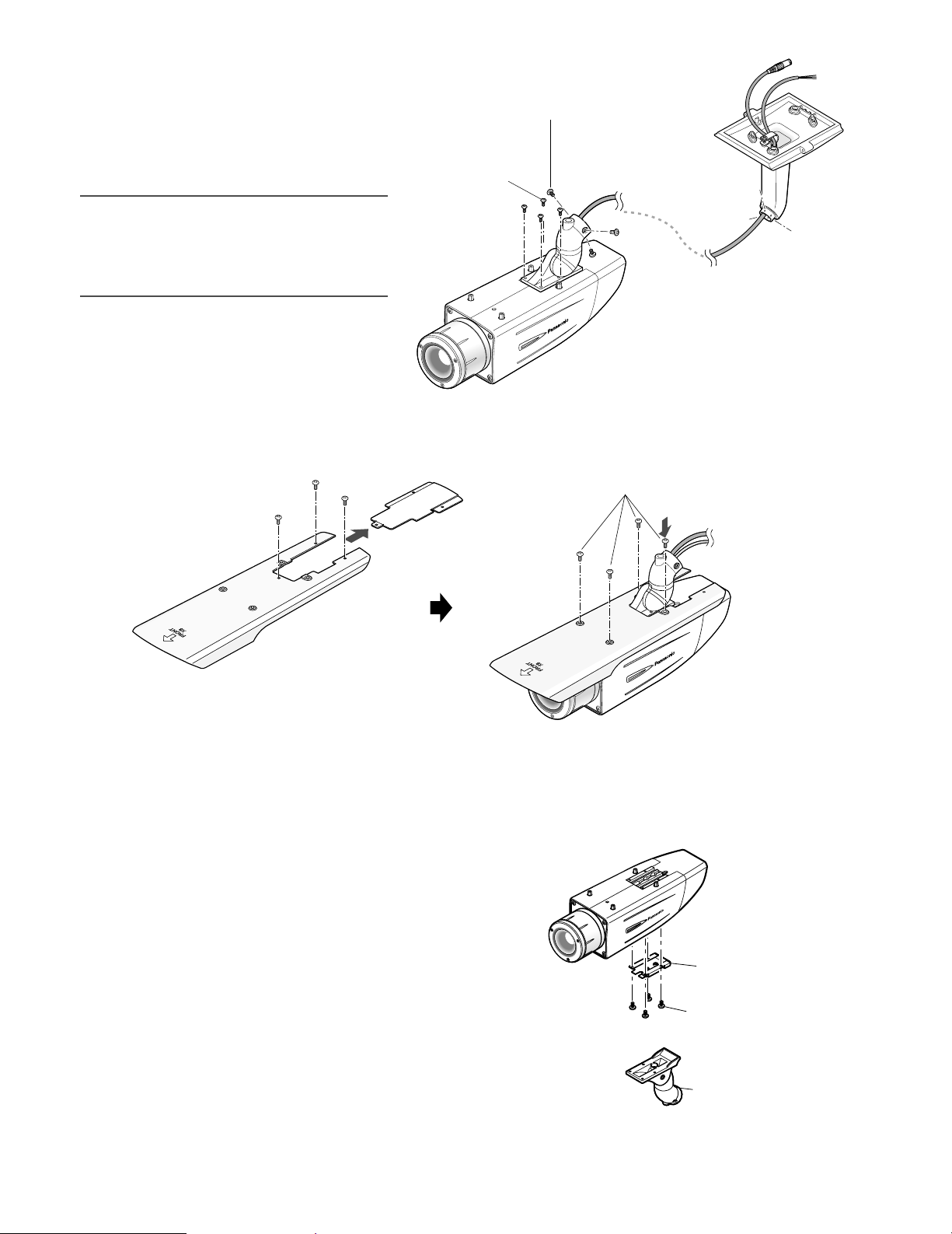
■ Camera installation
zSecure the camera to the camera mount bracket
The tilt angle is locked downward at shipment.
1. Loosen the tilting lock screw approx. 1 rotation and adjust the tilt angle of the camera to the horizontal position.
2. Tighten the tilting lock screw again after tilt angle adjustment.
Note:
• Use a hexagonal wrench with width across flats of 4 mm (locally procured) to loosen or tighten the tilting lock screw.
Tilting lock screw
Camera main body
Approx. 90°
3. Pass the video output cable, power cord and safety wire through the camera mount bracket from the camera side to the
wall side and use the cable clamp to bundle the cables and wire.
10

4. Secure the camera to the camera mount bracket with the 3 camera fixing screws (accessories).
Camera main body
Camera fixing screw x3 (M4 x 8) (accessories)
Safety wire
Video output cable
Power cord
Camera mount bracket
Mounting boss for safety wire
Video output cable
Power cord
Cable clamp
Drain slit
Camera mount bracket
5. Remove the screw from the mounting boss for safety wire of the camera mount bracket and secure the safety wire with the
screw.
Important:
• Ensure that the safety wire is firmly secured. Recommended tightening torque: 0.59 N·m {0.44 lbf·ft}
Important:
<Waterproof treatment>
• To install this product outdoors, be sure to
waterproof the cables. The camera main
body is waterproof, but the mount bracket
and adapter box are not waterproof.
Power cord
• To install this product outdoors, use waterproof silicon rubber or the like to apply
waterproof treatment to the camera mount
Video output cable
bracket, adapter box, cable access hole,
screw holes, and screws.
• To install this product on a wall, face the drain slit of the camera mount bracket downward. Do not block the drain slit.
Do not waterproof the drain slit, either.
• Be sure to use the supplied waterproof tape at the connection parts of the power cord and video output cable to apply
waterproof treatment.
<How to wind the supplied waterproof tape>
• Stretch the tape by approx. twice (see the illustration at right) and
wind it around the cables. Insufficient tape stretch causes insufficient waterproofing.
• Wind the cable with tape in a half-overlapping manner.
Stretch the tape to approx. twice.
Twice in length
11

xSecure the camera mount bracket
s
• When the camera is directly installed on a wall
Use 4 screws (locally procured) to secure the camera
mount bracket to a wall or a junction box (locally procured).
6 mm (W) x 10 mm (L) {1/4" (W) x 3/8" (L)}
(long hole)
Camera mount bracket
Mounting screw x4 (locally procured)
46 mm {1-13/16"}
Cable access hole
83.5 mm
{3-1/4"}
22 mm
{7/8"}
If a junction box is used, putting the boxes side by side
is recommended as shown in the illustration at right. (for
easy cable passing)
• When the camera is installed on a wall using the
adapter box
1. Use 4 screws (locally procured) to secure the adapter
box to a wall or a junction box (locally procured).
6 mm (W) x 10 mm (L)
{1/4" (W) x 3/8" (L)} (long hole)
Camera mount bracket
Mounting screw x4 (locally procured)
Hole 6 mm (W) x 10 mm (H)
{1/4" (W) x 13/32" (H)}
83.5 mm
{3-1/4"}
46 mm {1-13/16"}
Center of
adapter box
46 mm {1-13/16"}
Junction boxe
Cable access hole
24.5 mm
{31/32"}
22 mm
{14/16"}
83.5 mm
{3-5/16"}
12
• If a junction box is used, putting the boxes side by side
is recommended as shown in the illustration at right.
(for easy cable passing)
Cable access hole (used for wiring)
Mounting screw x4
(locally procured)
Hole
6 mm (W) x 10 mm (H)
{1/4" (W) x 13/32" (H)}
Mounting screw x4
(G3/4" internal thread)
(locally procured)
83.5mm
{3-5/16"}
Adapter box
46 mm {1-13/16"}
Junction boxes

2. Attach the camera mount bracket to the left
or right hinges of adapter box.
Adaptor box mounting screw (M4 x 35)
Hinges
Note:
• The right or left hinges of the adapter box shall be
selected so as to prevent the motion of the camera
mount bracket from being interfered with by obstructions such as a wall when the camera mount bracket is
connected to the hinges of the adapter box.
cSecure the mount bracket covers to the
camera mount bracket with the 2 mount
bracket cover screws (accessories).
II
SD
Mounting screw for adapter box/
camera mount bracket x4 (M5 x 20)
Adapter box
Mount bracket
Mount bracket cover x2
Mount bracket cover screw x2
(M3 x 6) (accessories)
Camera mount
bracket
13

* When using 12 V DC power supply,
the heater is unavailable.
To 24 V AC or 12 V DC
power supply
Video output cable
(Approx. 72 cm {28-3/8"})
Brown (Live)
Blue (Neutral)
Green/Yellow (GND)
To GND
BNC connector
BNC connector
To VIDEO IN
Power cord
(Approx. 72 cm {28-3/8"})
BNC connector
vMake a connection
Video output connection
The video output connector is connected to the monitor or
other system devices with a coaxial cable (locally procured).
The maximum extensible length is shown in the table.
Type of coaxial cable
Recommended
maximum cable
length
RG-59/U
(3C-2V)
m
250
ft 2 640
825
RG-6/U
(5C-2V)
500
1 650
RG-11/U
(7C-2V)
600
1 980
Power connection
Caution:
• The following connections should be made by qualified
service personnel or system installers in accordance
with NEC 725-51.
• Wire colors & functions
Camera power cord
Wire Color 24 V AC 12 V DC
Brown 24 V AC (L) Positive
Blue 24 V AC (N) Negative
Green/Yellow To GND To GND
Cautions:
• Be sure to connect the GND (grounding) lead of the
camera and grounding terminal of the power supply
when using a 24 V AC power source.
• Shrinking the cord-entry seal is a onetime procedure.
Do not shrink the cord-entry seal until it has been ascertained that unit is functioning.
• ONLY CONNECT THIS TO 24 V AC or 12 V DC CLASS
2 POWER SUPPLY.
• To prevent fire or electric shock hazard, the UL listed
wire VW-1 style 1007 should be used for the cord for
Input Terminals.
• Do not use a transformer larger than 10 VA.
14
RG-15/U
(10C-2V)
800
Cord length and wire gauge
24 V AC
The recommended cord length and copper wire size are
shown in the table for reference.
The voltage supplied to the camera should be between
19.5 V AC and 28 V AC.
Recommended wire gauge for 24 V AC line.
Copper wire
size (AWG)
Wire length
(Approx.)
m
ft
#24
(0.22 mm2)
20
66
#22
(0.33 mm2)
30
100
#20
(0.52 mm
45
150
2
12 V DC
The recommended resistance and copper wire size are
shown in the table for reference.
The voltage supplied to the camera should be between
10.5 V DC and 16 V DC.
Resistance of copper wire [at 20 °C {68°F}]
Copper wire
size (AWG)
Resistance (Ω/m)
Resistance (Ω/ft)
#24
(0.22 mm
0.078
0.024
2
)
(0.33 mm2)
#22
0.050
0.015
#20
(0.52 mm2)
0.03
0.009
"L", "R", "VA ", and "I" shall satisfy the inequality below.
10.5 V DC ≤ V
A - 2(R x I x L) ≤ 16 V DC
L : Cord length (m) {ft}
R : Resistance of copper wire (Ω/m){Ω/ft}
V
A : DC output voltage of power supply unit
I : DC current consumption (A). See the specification.
Important:
• When using 12 V DC power supply, the heater is
unavailable.
)
(0.83 mm2)
(0.83 mm2)
#18
75
250
#18
0.018
0.005

bBe sure to view the monitor for adjustment
when the camera angle is adjusted.
Supply power to this unit, connect the monitor for adjustment (e.g. a small LCD) to the monitor output connector,
and adjust the camera angle (turn off the power after view
angle adjustment for safety).
1. Loosen the 4 fixing screws of the lens cover to remove
the lens cover.
2. Connect the monitor for adjustment to the monitor output jack.
Lens cover
Fixing screw x4
Note:
• The plug dimensions in the illustration below shall be
observed for the monitor for adjustment.
Monitor output jack
(ø3.5 mm mini jack (monaural))
Important:
• After camera angle adjustment, the panning lock screw
and tilting lock screw shall be securely tightened.
Recommended tightening torque: 2.45 N·m {1.8 lbf·ft}
Notes:
• Use a hexagonal wrench with width across flats of 4
mm (locally procured) to loosen or tighten the panning
lock screw and tilting lock screw.
• Approximately 1 rotation of loosening the panning lock
screw and tilting lock screw allows camera angle
adjustment. Do not loosen the screws beyond necessity.
• The camera body shall be held when the panning lock
screw or tilting lock screw is loosened.
• Focus adjustment (☞ page 16) shall be performed
when panning and tilting adjustments are performed.
9 mm or less
{11/32"}
Straight type L-type
3. Repeat the steps (1) and (2) to adjust the camera
angle.
(1) Loosen the panning lock screw and rotate the cam-
era head horizontally to adjust panning.
(2) Loosen the tilting lock screw and rotate the camera
head vertically to adjust tilting.
(3) Tighten the panning lock screw and tilting lock
screw after camera angle adjustment.
9 mm or less
{11/32"}
Tilting lock screw
Panning lock screw
15

nAdjust the focus
Focus adjustment must be performed when camera angle
(☞ page 15) adjustment are performed.
1. Repeat the steps (1) and (2) to adjust the view angle
and focus.
(1) Rotate the zoom adjustment ring to adjust the view
angle between TELE and WIDE.
(2) Loosen the focus lock knob, make coarse adjust-
ment of the focus, and then tighten the focus lock
knob.
2. Press the auto back focus button after adjusting the view angle while viewing the monitor
for adjustment.
→ The focus position indicator is displayed in the lower part of the screen, and the back
focus is automatically adjusted.
3. To perform fine adjustment of the back focus after automatic back focus adjustment, use the operation buttons through the
setup menu. (☞ page 31)
Auto back focus button
Focus lock knob
Zoom adjustment ring
NEAR FAR
.........|..........
INDICATOR 255 FOCUSING
Notes:
• No operation for 10 seconds or more automatically clears the focus position indicator.
• To change the angle of view by moving the zoom adjustment ring, also move the focus lock knob to adjust the focus.
<How to adjust the focus>
• When an auto iris lens is used to shoot a photographic subject, the originally adjusted focus may be slightly off depending
on the iris state resulting from the focal depth of the lens. In such a case, open the aperture by darkening the subject as
much as possible in the same way of taking picture, and then adjust the focus. Defocus can be prevented.
Use of "ABF" of "BACK-FOCUS SETUP" in the setup menu (☞ page 31) allows users to adjust the focus optimally in the
range of the capability to automatically follow the variation in illuminance. (Note: The adjusted focal point is not necessarily
the same as the optimal focal point at the illuminance.)
• The out-of-focus level in the near-infrared light region may be higher than that in the visible light region.
Setting "C/L ←→ B/W" of "BACK-FOCUS SETUP" to "AUTO" or "PRESET" in the setup menu allows users to adjust the focus
in both the near-infrared light and visible light regions. (The variation in illuminance is not followed after focus adjustment.)
<How to use varifocal lens>
• Reset the back focus position to restore the default position before the back focus adjustment. (Hold down the right and
left buttons among the operation buttons simultaneously for 2 seconds or more, or move the cursor to "MANUAL-ADJ" of
"BACK-FOCUS SETUP" in the setup menu and hold down the right and left buttons simultaneously for 2 seconds or more
after pressing the setting button.)
16

<Fine adjustment of the back focus through the setup menu>
1. Loosen the 1 fixing screw of the rear cover to remove the rear cover.
2. Loosen the 2 fixing screws of the switch cover to remove the switch cover.
3. Hold down the setting button for 2 seconds or more to call up the top screen of the setup menu. And then adjust the
back focus. For further information, refer to page 35.
Rear cover Fixing screw x1 Switch cover Fixing screw x2
mMount the cover
1. Attach the desiccant (accessory) to the inner bottom side of the lens cover.
2. Mount the lens cover, switch cover, and rear cover.
Mouning lens cover
(1)(3)
(4)(2)
Fixing screw x4 Fixing screw x2 Fixing screw x1
Mouning switch cover Mouning rear cover
Set button
Rear coverSwitch cover
Important:
• The tightening torque described below shall be followed for the 2 fixing screws of switch cover and the 4 fixing screws of
lens cover.
Recommended tightening torque: 0.59 N·m {0.44 lbf·ft}
• Be sure to attach the desiccant (accessory). Refer to the instructions for the desiccant for how to attach it.
• The tightening sequence of the 4 fixing screws of the lens cover shall be observed and repeated twice as described in the
illustration above.
((1) → (2) → (3) → (4), twice)
17

,Mount the sunshield
Sunshield mounting screw x4 (M3 x 6) (accessories)
Mount the sunshield on the camera with the 4 sunshield mounting
screws (accessories).
Align the arrow
to lens direction.
Sunshield
III
SD
Camera main body
Notes:
• Be sure to use the 4 sunshield mounting screws (accessories). Recommended tightening torque: 0.59 N·m {0.44 lbf·ft}
• The "FRONT" side of the sunshield shall be on the lens side.
.When the mounting surface is changed to the top surface of the camera body
1. Remove the 4 tripod head fixing
screws from the camera body and
remove the tripod head.
2. Loosen the spacer fixing screw of the
tripod head and remove the spacer.
Tripod head fixing
screw x4
3. Loosen the fixing screw and remove the rear cover.
4. Position the cable clamp topside to pass the video output cable and power cord upward. And then, mount the
rear cover.
Spacer
Tripod head
Fixing screw x1Rear cover
Spacer fixing screw
Spacer
Cable clamp
Switch cover
5. Mount the tripod head on the top of the camera body with the 4 tripod head mounting screws that were removed in the
step 1.
Important:
• Caution shall be taken to prevent the video output cable and power cord from being caught between the camera body and
tripod head.
18
6. Secure the camera to the camera mount
bracket with the 3 camera fixing screws
(accessories).
Pass the video output cable, and power cord
Camera fixing screw x3
(M4 x 8) (accessories)
and safety wire through the camera mount
bracket and secure the safety wire to the
camera mount bracket.
Important:
Tripod head fixing
screw x4
Camera mount
bracket
• Be sure to use the screws that were removed
from the tripod head.
Recommended tightening torque: 0.59 N·m
{0.44 lbf·ft}
Camera main body
7. Mount the sunshield on the camera body with the 4 sunshield mounting screws (accessories) after removing the sunshield
backside.
Sunshield mounting screw x4 (M3 x 6) (accessories)
Rear part of sunshield
⁄0When the tripod socket (accessory) is used (when a different camera mount bracket is used)
1. Remove the 4 tripod head fixing screws from the camera body and remove the tripod head.
Disassemble the tripod head and pull out the video output cable and power cord.
2. Mount the tripod socket (accessory) with the 4 mounting
screws for tripod socket (accessories).
Camera main body
2. Mount the tripod socket
(accessory).
Mounting screw
for tripod socket x4
(M3 x 8) (accessories)
1. Remove the tripod head.
19

3. Use a safety wire (locally procured) to take measures against a fall of the camera according to the installation position.
Camera mount bracket Safety wire
For wall installation WV-831 WV-Q140
For ceiling installation WV-7010A WV-Q141
4. Hook the tip (ring portion) of the safety wire on the sunshield mounting stud and screw the sunshield to secure the safety
wire.
Safety wire
Sunshield mounting
stud
III
SD
Wall installation
Sunshield mounting
Ceiling installation
stud
S
D
Safety wire
III
5. Refer to the instructions of the safety wire for the following steps.
Important:
• Be sure to use the 4 mounting screws for tripod socket (accessories).
Use of screws with inappropriate length may damage the unit.
• The 4 screws removed from the tripod head cannot be used.
• The camera mount brackets, WV-831 and WV-7010A, and the safety wires, WV-Q140 and WV-Q141, are designed to be
used indoors. For outdoor installation, use the camera mount bracket in the accessories.
20

About Setup Menus
Before operation, setup of this camera is required. On the setup menu, you can check current settings and perform settings to
meet requirements.
The following is an example of setup procedure when "LANGUAGE" is set to "ENGLISH".
Settings items of the camera setup page
Setup item Description
CAMERA Configure the settings relating to camera operations
CAMERA ID The camera title can be edited and displayed on the screen.
ALC Configure the light control method.
SHUTTER Select the shutter speed.
AGC Select the method of the gain adjustment.
SENS UP Adjust the sensitivity.
SYNC Configure the method of the synchronization.
WHITE BAL Select the method of the white balance adjustment.
MOTION DET Configure the settings for the motion detection function.
DNR Configure the settings for the DNR (Digital Noise Reduction) function.
RESOLUTION Select a horizontal resolution mode.
BW MODE Configure the settings relating to the BW mode such as the settings for switching
between the color mode and the BW mode.
PRIVACY ZONE It is possible to mask a designated zone and as a privacy zone.
EL-ZOOM Adjust the electronic zoom.
STABILIZER Select "ON" or "OFF" to determine whether or not to use the image stabilizer to pre-
vent shaky images.
LED Performs the settings for LED.
BACK-FOCUS Select the method of the flange-back (back focal) length adjustment and adjust the
flange-back (back focal) length minutely.
SPECIAL
CHROMA GAIN Adjust the chroma level (color density).
AP GAIN Adjust the aperture level.
PEDESTAL Adjust the pedestal level (brightness).
HUE Adjust the chroma phase.
PIX OFF Correct image defects such as scratches.
CAMERA RESET Reset the settings of setup menu to the default settings.
SER.NO. Check the serial number of this camera.
LANGUAGE Select the language to display the setup menu.
Reference
Pages
23
24
25
26
26
26
27
27
29
29
29
30
30
31
31
31
32
32
32
32
32
33
33
33
23
21

■ Basic operation
The following are descriptions of how to configure each setup item using the operation buttons (refer to page 8) on the camera. Setup using an optional system controller is also available.
Note:
• The illustrations below are the examples to be displayed on a video monitor.
1. Hold down the [SET] button for around 2 seconds.
→ The top page will be displayed.
2. Move the cursor onto "END" by press the [UP] or [DOWN] button.
3. Press the [SET] button after moving the cursor onto "SETUP" by
pressing the [RIGHT] button.
→ The "DISABLE" indication will change into "ENABLE" and
the settings will become editable.
4. Move the cursor onto the desired setup item and press the
[SET] button.
→ The setup page of the selected setup item will be dis-
played.
5. Configure the settings for each item.
Select setup item: Move the cursor by pressing the [UP] or
[DOWN] button.
Change the parameter: Press the [LEFT] or [RIGHT] button.
Display the detailed settings page of the setup item: Press
the [SET] button when the setup item with the [O] mark is
selected.
Go back to the previous page: Move the cursor onto "RET"
and press the [SET] button.
Go back to the top page: Move the cursor onto "TOP" and
press the [SET] button.
MODEL WV-CW384
CAMERA
BACK-FOCUS
SPECIAL
LANGUAGE
END SETUP DISABLE
MODEL WV-CW384
CAMERA
BACK-FOCUS
SPECIAL
LANGUAGE
END SETUP ENABLE
**CAMERA SETUP** 1/2
CAMERA ID OFF
ALC ALC
SHUTTER OFF
AGC ON(HIGH)
SENS UP OFF
SYNC INT
WHITE BAL ATW1
MOTION DET OFF
DNR HIGH
RESOLUTION HIGH
BW MODE
**CAMERA SETUP** 2/2
PRIVACY ZONE OFF
EL-ZOOM OFF
STABILIZER OFF
LED ON
RET TOP END
6. To exit from the SETUP menu and display images from the camera, move the cursor onto "END" and press the [SET] button.
Notes:
• To prevent erroneous operations, the "DISABLE" indication will always be displayed when the top page is displayed from
the camera. To operate the SETUP menu, switch the "DISABLE" indication to the "ENABLE" indication first.
• The cursor position will be displayed highlighted.
22

Setting Procedures
First, select a language for menu display and camera ID display.
Language Setup (LANGUAGE SETUP)
1. Select "LANGUAGE" on the top menu and press the [SET] button.
→ The "LANGUAGE SETUP" menu opens.
2. Select a language. The default setting is "ENGLISH".
Available languages: ENGLISH, FRANÇAIS, ESPAÑOL,
DEUTSCH, ITALIANO, кмллдав, CHINESE or JAPANESE
3. Select "SET" on the menu and press the [SET] button.
1. Camera Identification Setting (CAMERA ID)
Assign a name to the camera using up to 16 characters to display it overlaying on the camera picture in the selected position.
Note:
• If you change the language selection after the assignment of camera ID, it will be erased.
**LANGUAGE SETUP**
LANGUAGE ENGLISH
SET
RET TOP END
1. On the "CAMERA SETUP" menu, select "ON↓" or "OFF↓" for
"CAMERA ID" and press the [SET] button.
ON↓: Displays entered camera ID.
OFF↓: Does not display the ID.
→ The "CAMERA ID" menu opens.
2. Select a character from the character area and press the [SET]
button.
→ The selected characters are displayed in the editing area.
3. Repeat these procedures until all characters are entered.
• To enter a blank space, select "SPACE" and press the [SET]
button.
• To replace a specific character in the editing area:
1. Move the cursor to the editing area and then move the
pointer to the character to be replaced pressing the
[LEFT] and [RIGHT] buttons.
2. Move the cursor to a candidate character in the character
area and press the [SET] button.
• To erase all characters of the camera ID, select "RESET" and
press the [SET] button.
Note:
• For Chinese language, up to 8 characters can be entered.
**CAMERA SETUP** 1/2
CAMERA ID OFF
ALC ALC
SHUTTER OFF
AGC ON(HIGH)
SENS UP OFF
SYNC INT
WHITE BAL ATW1
MOTION DET OFF
DNR HIGH
RESOLUTION HIGH
BW MODE
CAMERA ID
0123456789
ABCDEFGHIJKLM
NOPQRSTUVWXYZ
().,'":;&#!?=
+-*/%$
SPACE POSI
RET TOP END RESET
................
FLOOR 1
Character
Cursor
Character
Area
Command
Editing
Area
Pointer
Highlighted
23
 Loading...