

Page 1
Color CCTV Camera
Operating Instructions
Model No. WV-CS854B
Before attempting to connect or operate this product,
please read these instructions carefully and save this manual for future use.
FRANÇAIS
ENGLISH
Page 2
-2-
WARNING: To prevent fire or electric shock hazard, do not expose this appliance to rain or moisture. The apparatus shall not be exposed
to dripping or splashing and that no objects filled with liquids, such as vases, shall be placed on the apparatus.
The serial number of this product may be found on the top
of the unit.
You should note the serial number of this unit in the space
provided and retain this book as a permanent record of your
purchase to aid identification in the event of theft.
Model No. WV-CS854B
Serial No.
NOTE: This equipment has been tested and found to comply
with the limits for a Class A digital device, pursuant to Part
15 of the FCC Rules. These limits are designed to provide
reasonable protection against harmful interference when the
equipment is operated in a commercial environment. This
equipment generates, uses, and can radiate radio frequency
energy and, if not installed and used in accordance with the
instruction manual, may cause harmful interference to radio
communications.
Operation of this equipment in a residential area is likely to
cause harmful interference in which case the user will be
required to correct the interference at his own expense.
FCC Caution: To assure continued compliance, (example use only shielded interface cables when connecting to
computer or peripheral devices). Any changes or modifications not expressly approved by the party responsible for
compliance could void the user’s authority to operate this
equipment.
For U.S.A
This Class A digital apparatus complies with Canadian
ICES-003.
For Canada
The lightning flash with arrowhead
symbol, within an equilateral triangle, is
intended to alert the user to the
presence of uninsulated "dangerous
voltage" within the product's enclosure
that may be of sufficient magnitude to
constitute a risk of electric shock to
persons.
The exclamation point within an
equilateral triangle is intended to alert
the user to the presence of important
operating and maintenance (servicing)
instructions in the literature accompanying the appliance.
SA 1965
SA 1966
CAUTION: TO REDUCE THE RISK OF ELECTRIC SHOCK,
DO NOT REMOVE COVER (OR BACK).
NO USER-SERVICEABLE PARTS INSIDE.
REFER SERVICING TO QUALIFIED SERVICE PERSONNEL.
CAUTION
RISK OF ELECTRIC SHOCK
DO NOT OPEN
ENGLISH VERSION
Page 3

-3-
IMPORTANT SAFETY INSTRUCTIONS
1) Read these instructions.
2) Keep these instructions.
3) Heed all warnings.
4) Follow all instructions.
5) Do not use this apparatus near water.
6) Clean only with dry cloth.
7) Do not block any ventilation openings. Install in accordance with the manufacturer's instructions.
8) Do not use near any heat sources such as radiators, heat registers, stoves, or other apparatus (including
amplifiers) that produce heat.
9) Do not defeat the safety purpose of the polarized or grounding-type plug. A polarized plug has two blades with
one wider than the other. A grounding-type plug has two blades and a third grounding prong. The wide blade or
the third prong are provided for your safety. If the provided plug does not fit into your outlet, consult an
electrician for replacement of the obsolete outlet.
10) Protect the power cord from being walked on or pinched particularly at plugs, convenience receptacles and the
points where they exit from the apparatus.
11) Only use attachments/accessories specified by the manufacturer.
12) Use only with the cart, stand, tripod, bracket, or table specified by the manufacturer, or sold with the apparatus.
When a cart is used, use caution when moving the cart/apparatus combination to avoid injury from tip-overs.
13) Unplug this apparatus during lightning storms or when unused for long periods of time.
14) Refer all servicing to qualified service personnel. Servicing is required when the apparatus has been damaged
in any way, such as power-supply cord or plug is damaged, liquid has been spilled or objects fallen into the
apparatus, the apparatus has been exposed to rain or moisture, does not operate normally, or has been
dropped.
ENGLISH
S3125A
Page 4

-4-
Page 5

-5-
CONTENTS
PREFACE .......................................................................................................................... 6
FEATURES ........................................................................................................................ 6
■ Camera Cleaning ....................................................................................................... 7
■ Preset Data Uploading or Downloading .................................................................... 7
PRECAUTIONS ................................................................................................................. 7
CONSTRUCTION ............................................................................................................. 9
SETUP ............................................................................................................................ 10
■ Setup Menu ............................................................................................................. 10
■ Setup Menu Description ............................................................................................ 13
SETTING PROCEDURES .................................................................................................. 17
■ Menu Display ............................................................................................................. 17
■ Preset Menu ............................................................................................................... 18
■ Deleting Preset Positions ........................................................................................... 22
■ Home Position Setting (HOME POSITION) ................................................................ 23
■ Self Return Setting (SELF RETURN) .......................................................................... 23
■ Auto Mode Selection (AUTO MODE) ......................................................................... 23
■ Auto Pan Key Setting (AUTO PAN KEY) .................................................................... 25
■ Digital Flip Setting (DIGITAL FLIP) ............................................................................ 25
■ Special 1 Menu Setting (SPECIAL 1) ......................................................................... 27
■ Camera Setting .......................................................................................................... 34
■ RS485 Setup .............................................................................................................. 43
INSTALLATION ................................................................................................................. 45
CONNECTIONS ................................................................................................................ 50
SYSTEM CONNECTIONS ................................................................................................. 52
SPECIFICATIONS ............................................................................................................. 53
ACCESSORIES ................................................................................................................. 54
OPTIONAL ACCESSORIES .............................................................................................. 54
APPENDIX ........................................................................................................................ 55
Page 6

PREFACE
Panasonic presents highly advanced CCTV technology
that meets the demands of new and ever-changing
applications.
This high-performance combination color camera is
utilized as a video surveillance device.
The camera incorporates Super-Dynamic
2 Digital
Signal Processor, pan-tilt mechanism, 22 zoom lens
and RS485 communication in a compact enclosure.
• High quality picture of 768 x 494 pixels
• Minimum illumination of 1 lx for color and 0.06 lx for
black/white surveillance
• Super-Dynamic
2 extends the dynamic range up to
48 dB.
• Privacy zone feature enables users to veil unwanted
zones.
• Protocol adaptability to Panasonic's protocol
• Auto black/white mode enables the camera to
switch between C/L and B/W in response to input
lights.
• Reduction in minimum illuminance to 0.03 lx in the
black/white mode thanks to PIX SENS UP
• Digital flip allows 180° tilting to trace objects
passing under the camera.
Digital Flip Operation
-6-
A newly developed 1/4-inch CCD is employed for use
under extremely low light conditions: 0.06 lx for
monochrome and 1 lx for color.
It also assures clear display of pictures in which bright
and dark objects coexist without mutual interference
thanks to Super-Dynamic
2 DSP. Setup menus allow
the camera to fulfill surveillance tasks by such means
as Motion Detector, Digital Flip, Patrol Learn and
Privacy Zones.
FEATURES
• A run of manual operations is memorized in the
patrol-learn mode for repetitive use in future.
• Built-in digital motion detector and alarm outputs
• Up to 64 preset positions
• 360° panning at a rotation speed of 300 °/s
• Sync selectable from among internal, line-lock and
VD2
• Automatic gain control circuit
• Image hold
• Digital noise reduction effect
• Setting change executable only by authorized
personnel thanks to the password lock function
• Enhanced horizontal resolution by resolution setting
q Tilting down w The picture is
turned upsidedown instantly
around at 135
degrees of the tilt
angle.
e Tilting down
0°
180°
0°
180°
0°
180°
Page 7

-7-
■ Camera Cleaning
Even if this function is used, noise may be produced
on the monitor screen, or the preset position may
deviate in the course of prolonged use.
In such cases, activate the refresh mode on the special
2 menu. (See page 42.)
To use this camera with WJ-SX550C, WJ-SX150 Matrix
Switcher, set the auto cleaning function activated on
the Matrix Switcher side, then clean WV-CS854B once
a day.
■ Preset Data Uploading or Downloading
To download the preset data from the camera to the
controller or upload the downloaded data to the
camera, set the following functions to OFF.
Downloading or uploading the data may not work
normally if these functions are set to ON.
• Alarm (see page 31)
• Preset alarm (see page 33)
• Cleaning (see page 32)
• Motion detection (see page 39)
• Auto mode (see page 23)
• Self return (see page 23)
Aim the camera at a motionless object such as a wall,
if possible, to download or upload the preset data.
Note: Take notice of the following when uploading the
downloaded data to the camera.
• Preset positions may vary. If a preset position has
deviated, delete the preset position and set the
correct preset position newly.
• Uploading of WV-CS854B preset data to other
models (e.g. WV-CS854, WV-CS854A and WVNS324) may cause an error and failure of the
uploading process.
PRECAUTIONS
1. Do not attempt to disassemble the camera.
To prevent electric shock, do not remove screws or
covers.
There are no user-serviceable parts inside.
Ask qualified service personnel for servicing.
2. Handle the camera with care.
Do not misuse the camera. Avoid striking, shaking,
etc. The camera could be damaged by improper
handling or storage.
3. Do not expose the camera to rain or moisture,
nor try to operate it in wet areas.
This product is designed for indoor use or locations
where it is protected from rain and moisture.
Turn the power off immediately and ask qualified
service personnel for servicing.
Moisture can damage the camera and also create
the danger of electric shock.
4. Do not use strong or abrasive detergents when
cleaning the camera body.
Use a dry cloth to clean the camera when it is dirty.
When the dirt is hard to remove, use a mild
detergent and wipe gently. Care should be taken
not to scratch the dome cover when wiping it.
Afterwards, wipe off the remaining detergent with a
dry cloth.
5. Never aim the camera at the sun.
Whether or not the camera is in use , never aim it at
the sun or other extremely bright objects.
Otherwise, blooming or smear may be caused.
6. Never aim the camera at strong light sources for
an extended period of time.
A light source such as a spot light causes burn-in
on the display screen. Failure to observe this may
cause the image to become discolored due to
deterioration of the color filter in the CCD.
7. Do not install this camera upside down.
This camera is designed for mounting on the ceiling
or wall. Using this camera installed upside down,
for example, mounted on the floor, may cause
malfunction.
8. If "OVER HEAT" appears on the monitor screen.
The temperature inside the camera exceeds the
normal level because of a malfunction of the
cooling fan or other reasons. If this happens, turn
the power off immediately and refer servicing to
qualified service personnel.
Page 8

-8-
9. Do not operate the camera beyond the specified
temperature, humidity or power source ratings.
Do not use the camera in an extreme environment
where high temperature or high humidity exists. Do
not place the camera near heat sources such as
radiators, stoves or other units that produce heat.
Use the camera under conditions where
temperature is between –10 °C - +50°C (14 °F 122 °F), preferably +40°C (104 °F)], and humidity is
below 90 %.
The input power source is 24 V AC 60 Hz.
10.Do not install the camera near the air outlet of an
air conditioner.
The lens may become cloudy due to condensation
if the camera is used under the following
conditions.
• Rapid temperature fluctuations by switching the air
conditioner on and off.
• Rapid temperature fluctuations due to frequent door
opening and closing.
• Use in an environment where eyeglasses become
foggy.
• Use in a room filled with cigarette smoke or dust.
If the lens becomes cloudy due to condensation,
remove the dome cover and wipe all moist surfaces
with a soft cloth.
11.Consumables
Parts having contacts such as the lens-drive
motors, cooling fan motor and slip-rings inside the
camera are subject to wear with time. Please ask
the nearest service center about replacement and
maintenance of such parts.
12.Do not aim the camera at the same object for a
long time.
Burn-in of an image may be caused on the
fluorescent screen of CRT.
13.Self-diagnosis Function
If the camera continues operating abnormally for 30
seconds or more due to such an accident as
external noise, the camera will automatically reset
its power. In the case it happens frequently, check
if there would be any environmental cause.
14.Prevention of blooming and smear
When the camera is aimed at a bright light source,
such as a spotlight, or a surface that reflects bright
light, smear or blooming may appear. Therefore,
the camera should be operated carefully in the
vicinity of extremely bright objects to avoid smear
or blooming.
* Matsushita Electric Industrial Co., Ltd. herewith
declares that it will not be liable for any damage,
whether direct or indirect, caused by using the
product for business transaction or security, or
malfunctioning of this product.
Bright object
Smear
Page 9
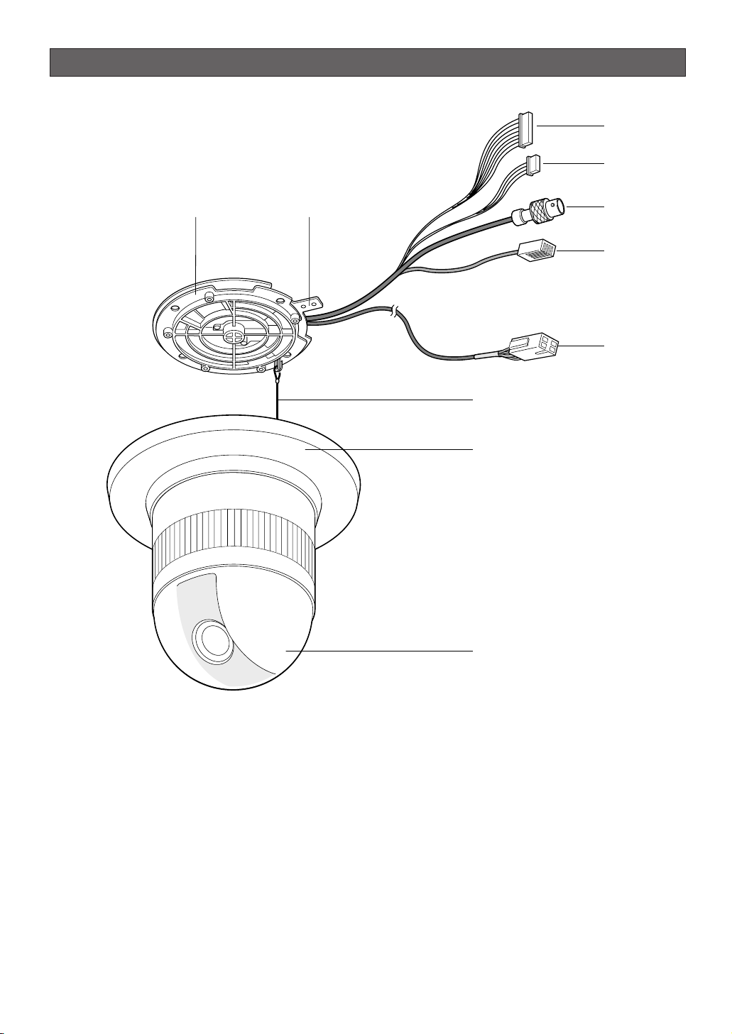
CONSTRUCTION
q Alarm Input Connector
w Alarm Output Connector
e Video Output Connector
r Data Port
t Power Cable
y Camera Mounting Base
u Panning Start Point
i Fall Prevention Wire
o Decoration Cover
!0 Dome Cover
-9-
q
w
yu
e
r
t
i
o
!0
Page 10

SETUP
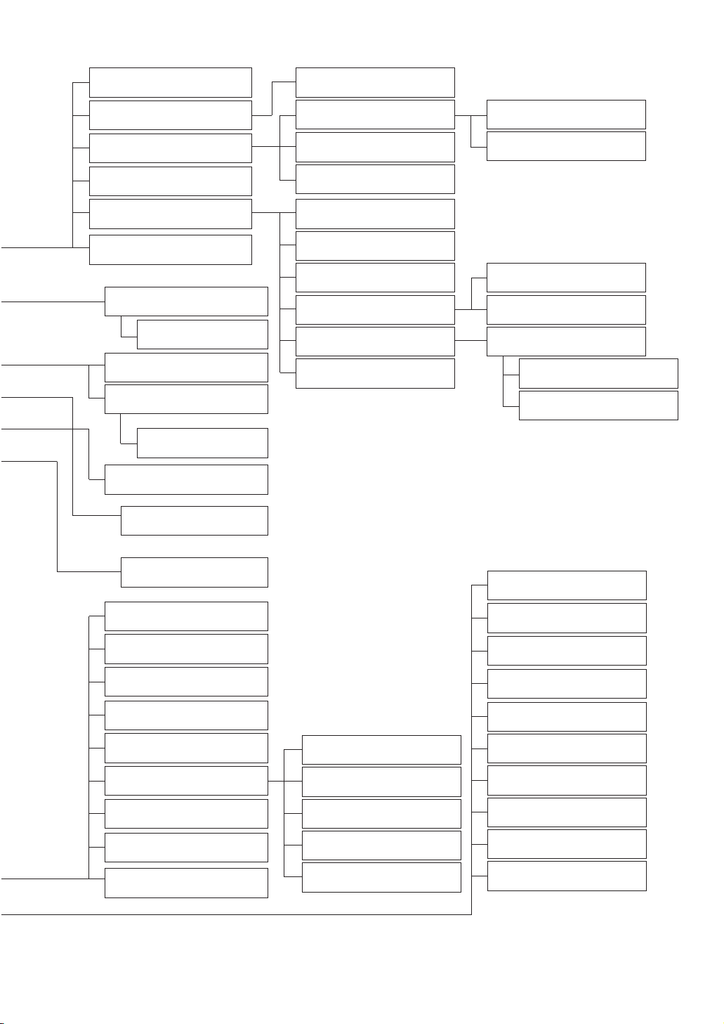
■ Setup Menu
Setup menus are shown in the diagram below. You can adapt the camera to your requirements by setting up the
respective items in these menus. Menus are incorporated in a hierarchical structure, from the setup menu at the top
to manual mask area selection at the bottom. These menus are described on the following pages for reference.
Switches, keys and the joystick are used in the setup operations.
-10-
Setup Menu
Preset Menu (P. 18)
Map Menu
Home Position Setting (P. 23)
Self Return Setting (P. 23)
Auto Mode Selection (P. 23)
Auto Pan Key Setting (P. 25)
Special 1 Menu (P. 27)
Digital Flip Setting (P. 25)
Camera Menu (P. 34)
Camera ID Editing (P. 34)
Light Control Setting (P. 35)
Shutter Speed Setting (P. 36)
AGC Mode Selection (P. 36)
Electronic Sensitivity
Enhancement (P. 36)
Synchronization (P. 37)
White Balance (P. 38)
Motion Detector (P. 39)
Auto Focus Setting (P. 40)
Special 2 Menu (P. 40)
RS-485 Setup (P. 43)
Password Lock (P. 26)
Preset No.Setting (P. 18)
Preset Setting Menu
(P. 18)
Auto Pan Setting (P. 25)
INT Manual Selection (P. 37)
LL Manual Selection (P. 37)
VD2 Automatic Selection
(P. 37)
Manual Level Adjustment
(ATW1, ATW2) (P. 38)
Manual Level Adjustment
(AWC) (P. 38)
Sensitivity Level Adjustment
(P. 39)
Manual Mask Area
Selection (P. 35)
Camera ID Display Position
(P. 34)
ALC Mode with Super-D2 ON
(P. 35)
V-phase Manual
Adjustment (P. 37)
Privacy Zone ON/OFF
(P. 27)
Proportional Pan/Tilt
(P. 28)
Area Title (P. 28)
Patrol Learn (P. 30)
Alarm IN/OUT (P. 31)
Cleaning (P. 32)
Electric Zoom (P. 32)
Preset Alarm (P. 33)
Image Hold (P. 33)
Tilt Angle (P. 33)
Mask Area Selection
(P. 39)
Demonstration Display
Password Registration
(P. 26)
Password Verification (P. 26)
ALC Mode with Super-D2
OFF (P. 35)
Page 11
-11-
Position Setting (P. 18)
Dwell Time Setting (P. 21)
Chroma Level Setting (P. 40)
Aperture Level Setting (P. 40)
Pedestal Level Setting (P. 40)
Resolution (P. 40)
Digital Noise Reduction
(P. 41)
BW Mode (P. 41)
PIX OFF Setting (P. 42)
Super-D2 OFF (P. 35)
Preset ID Editing (P. 18)
Super-D2 ON (P. 35)
Manual Iris Adjustment (P. 35)
Shutter Speed (P. 36)
Gain Control (P. 36)
Electronic Sensitivity
Enhancement (P. 36)
White Balance (P. 38)
Motion Detector (P. 39)
Auto Focus (P. 40)
Unit Number (P. 43)
Sub Address (P. 43)
Baud Rate (P. 43)
Data Bit (P. 43)
Parity Check (P. 43)
Stop Bit (P. 43)
X On/X Off (P. 43)
Wait Time (P. 43)
Alarm Data (P. 43)
Delay Time (P. 43)
Light Control Setting (P. 21)
To Restore the Camera Default
Position (P. 42)
Camera Resetting (P. 42)
Zone Number Selection (P. 27)
Zone Parameter Setting
(P. 27)
Setting for ON (USER) (P. 29)
Setting for ON (NESW) (P. 28)
Area Title Display (P. 29)
Learning Display (P. 30)
Alarm IN/OUT Setting (P. 31)
Cleaning Display (P. 32)
Scene File Setting (P. 21)
Preset Speed (P. 22)
B/W AUTO/ON/OFF (P. 41)
B/W Auto Sensitivity Level
(P. 41)
B/W Auto Duration Time Setting
(P. 41)
Pixel SENS UP (P. 41)
Burst Setting (P. 41)
Manual Level Adjustment
(Contrast) (P. 36)
Manual Mask Area Selection
(P. 35)
Manual Level Adjustment
(ATW1, ATW2) (P. 38)
Sensitivity Level Adjustment
(P. 39)
Mask Area Selection (P. 39)
Demonstration Display
Manual Level Adjustment
(AWC) (P. 38)
Preset Identification Setting
(P. 20)
Page 12
-12-
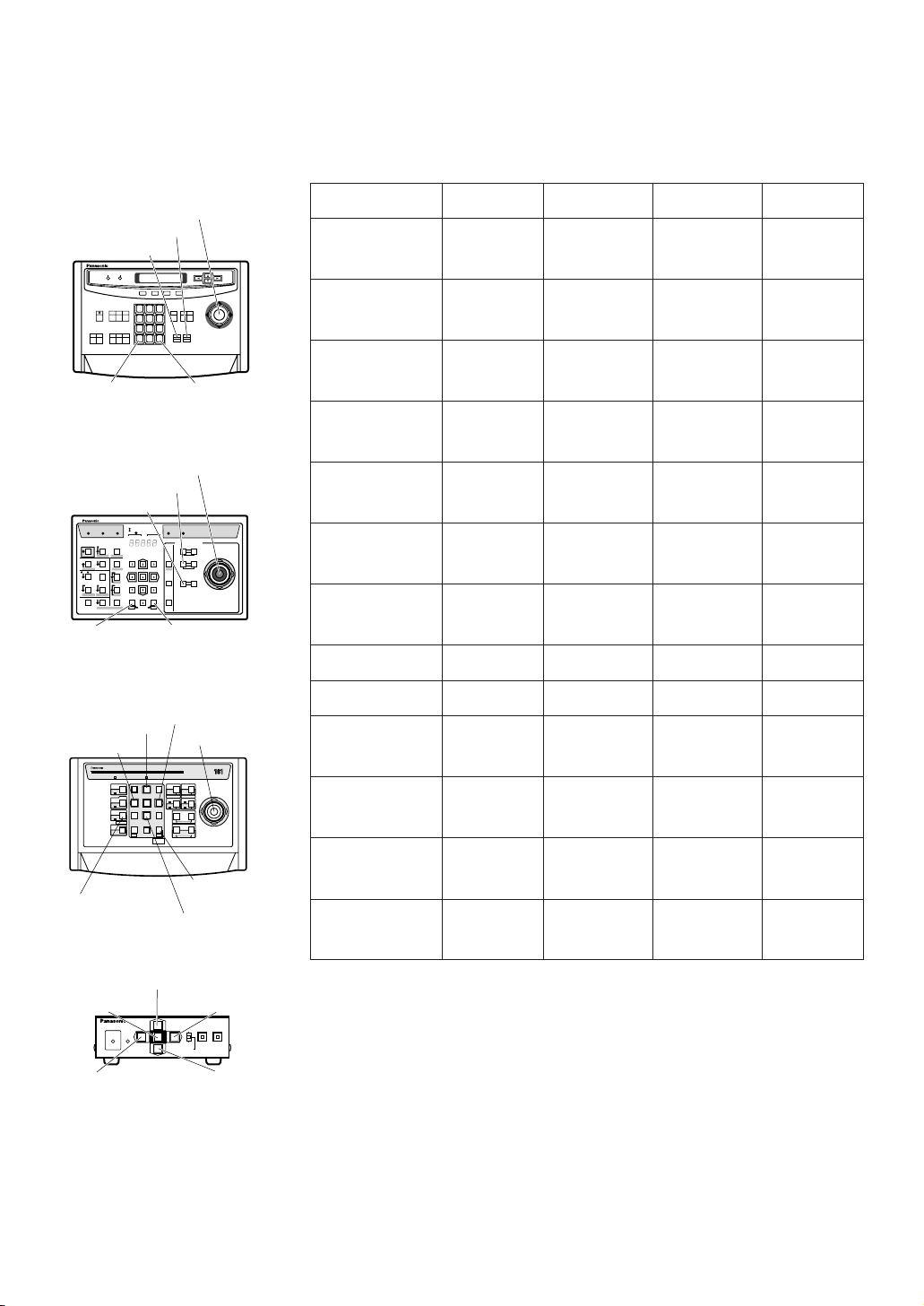
The keys (switches) to be used for setup are shown in the table below. The joystick on the connected controller may
also be used for setup. The table also shows the functions and the operations of the individual controllers. For details,
see the manual for the controller to be used. Switches and controls are abbreviated as SW and CTRL respectively in
the table.
Notes:
• A changed parameter is entered only when you move the cursor to another
item or open a new menu. If you close the setup menu without either of the
above actions, the changed parameter will not be entered.
• Setting procedures on the following pages are described on the assumption
that the camera is used with WJ-SX550C Matrix Switcher and WVCU550C/CJ System Controller.
Open Special 2 F2 key
Function/Controller WV-CU550C/CJ WV-CU360C/CJ WV-CU161C WV-RM70
Open CAM SETUP See page 17
CAM SETUP key
(for 2 seconds or
more)
CAMERA SETUP
key (for 2 seconds or more)
See page 17
Close CAM SETUP F4 key
CAM SETUP key
(for 2 seconds or
more)
CAMERA SETUP
key (for 2 seconds or more)
PROG SW
Move the cursor
Joystick
(
←, ↑, ↓, →)
Joystick
(←, ↑, ↓, →)
Direction SW
(←, ↑, ↓, →)
Direction SW
(←, ↑, ↓, →)
Select a parameter
Joystick
(
←, →)
Joystick
(←, →)
Direction SW
(←, →)
Direction SW
(←, →)
Adjust the level
Joystick
(
←, →)
Joystick
(←, →)
Direction SW
(←, →)
Direction SW
(←, →)
Move the camera
direction
Joystick
(
←, ↑, ↓, →)
Joystick
(←, ↑, ↓, →)
Joystick
(←, ↑, ↓, →)
Direction SW
(←, ↑, ↓, →)
Zoom & Focus
ZOOM CTRL &
FOCUS CTRL
ZOOM CTRL &
FOCUS CTRL
ZOOM CTRL &
FOCUS CTRL
Direction SW
(
←, ↑, ↓, →)
Enter the setting CAM (SET) key CAM (SET) key CAM (SET) key SET SW
Open a submenu CAM (SET) key CAM (SET) key CAM (SET) key SET SW
Enter CAM ID &
PRESET ID
display position
MON (ESC) key MON (ESC) key SET key
SET SW
(for 2 seconds)
Enter MASK
setting
MON (ESC) key MON (ESC) key SET key
SET SW
(for 2 seconds)
All Reset F3 key
4+5+6 key
(for 2 seconds or
more)
4+5+6 key
(for 2 seconds or
more)
R+SET+L SW
(for 2 seconds)
4+6 key
(for 2 seconds or
more)
4+6 key
(for 2 seconds or
more)
R+L SW
(for 2 seconds)
OPERATE LOGIN ALARM
FUNCTION
SX
IRIS
CLOSE OPEN
NEAR FAR
WIDE TELE
FOCUS
ZOOM
AUTO FOCUS
IRIS RESET
HOME
SET UP
ALM RECALL
CAM SETUP
CAM FUNCTION
MULTI SCREEN
DEF
WIPER
EL-ZOOM
SHIFT
ALM RESET
VTR CAM
STILL
-1 CAM/DEC
ALM SUSPEND
+1 CAM/INC
PATROLSTOP
AUX 1
AUX 2
B/W UNIT
SEQ PAUSE
BOOST
SEQUENCE AUTO
PRESET
POSI
FS
MON
CAM
LOGOUT
ESC SET
CAMERA SITE CONTROL
UP
LR
DOWN
BUSY PROHIBITED
MONITOR
UNIT
CAMERA
System Controller
WV-CU
360
1 2 3
4 5 6
7 8 9
MON CAM
ESC SET
0
ACK
RESET
BACK
SEQ
FORWARD
SEQ ALT
DEC
–1CAM
INC
+1CAM STOP
12
AUX
CLOSE OPEN
IRIS
PRESET
FOCUS
NEAR
ZOOM
TELE
FARWIDE
System Controller WV-CU550550C
LEFT RIGHT
UP
DOWN
ALARM BUSY
F3 F4F2F1
AF
[WV-CU550C/CJ]
[WV-CU161C]
[WV-RM70]
Joystick
CAM (SET)
Key
MON (ESC)
Key
CAM (SET)
Key
MON (ESC)
Key
SET Key
CAM (SET) Key
OPERATE
REMOTE
NORMAL PROG
ALARM
RESET
SYSTEM
ALARM OFF
Camera Controller WV-RM
707070
Up Switch
Set Switch
Right
Switch
Left Switch Down
Switch
[WV-CU360C/CJ]
Joystick
Joystick
FOCUS Switch
ZOOM Switch
FOCUS Switch
ZOOM Switch
Up Switch
R
System Controller WV-CU
1 2 3
4 6
7 8 9
0
5
SHIFT
OPERATE ALARM
RESET
RESET
SUSPEND
CAMERA
SETUP
PATROL
PAY
PROGRAM
PRESET
CAMERA
FUNCTION
SERUP
ESC
HOME
SET
PRESET
WIDE TELE
NEAR
AUX1
B/W
AUTO
WIPER
AUX2
DEF
UP
DOWN
L
FAR
FOCUS
IRIS
CLOSS OPEN
PROGRAM
ALARM
IRIS RESET
AUTO FOCUS
Left Switch
Right Switch
Down Switch
Page 13

-13-
■ Setup Menu Description
● Presetting
(1) Position (POSITION SET)
Aligns the camera position and focal point by
panning, tilting, zooming and focusing.
See page 18 for the setting.
(2) Preset Identification (PRESET ID)
Assigns the name for preset IDs (identification of up
to 16 alphanumeric characters) and can be
switched on or off on the monitor screen.
See page 20 for the setting.
(3) Light Control (ALC/MANUAL)
Selects the ALC or MANUAL mode for adjusting the
lens iris.
See page 21 for the setting.
(4) Dwell Time (DWELL TIME)
Displays the picture at each camera position for the
selected duration.
You can select a preset duration from the menu.
See page 21 for the setting.
(5) Scene File (SCENE FILE)
Stores up to 10 files.
Each file has a set of detailed parameters for the
shutter speed, AGC, electronic sensitivity
enhancement, white balance, motion detector and
AF mode. The scene files can be recalled later to
reproduce the parameter settings under the same
conditions as stored in the files.
See page 21 for the setting.
● Home Position (HOME POSITION)
The home position is the camera’s basic position.
The camera returns to this position automatically after a
specific time following a manual operation. This setting
functions only when AUTO MODE is OFF.
See page 23 for the setting.
● Self Return (SELF RETURN)
The self return function allows the camera to resume
one of the operations described below after specified
time.
This function automatically works after a lapse of
setting time from manual operation finished.
OFF: Cancels the auto mode (SEQ, SORT, AUTO
PAN and PATROL).
AT (the auto mode is set to OFF): Shifts the
camera direction to the home position.
AT (the auto mode is set to other than OFF):
Activates the auto mode.
HP: Shifts the camera direction to the home
position.
AP: Starts the auto pan function.
SQ: Starts the sequence function.
SR: Starts the sort function.
PT: Starts the patrol function.
See page 23 for the setting.
● Auto Mode (AUTO MODE)
The auto mode is used for setting the movement of the
camera.
You can select one of four automatic operation modes
and one manual operation mode as follows:
OFF: No automatic operation. The camera can be
operated only manually.
SEQ: The camera operates in the sequence of preset
positions in numerical order.
SORT: The camera operates in the sequence of preset
positions counterclockwise from pan starting point.
AUTO PAN: The camera automatically turns within the
preset panning range.
PATROL: The camera operates in the patrol-learn
function.
See page 30 for the setting.
● Auto Pan Key (AUTO PAN KEY)
This setting assigns the SEQ, SORT, AUTO PAN or
PATROL (PLAY) mode to the AUTO key on the
controller.
After this setting, the AUTO key performs as assigned.
Note: The AUTO PAN LED on the controller does not
light if a mode other than AUTO PAN is assigned.
● Digital Flip (DIGITAL FLIP)
Tilt range is limited within –5 ° to 90° if OFF is selected.
If ON is selected it widens the range up to 190 ° with
the digital flip that reverses horizontal and vertical
scanning when the camera is tilted beyond 90 ° point
(Downright position if the camera is installed on a
ceiling). Tilt range narrows from –5 ° to 90 ° if PAN
LIMIT is set to ON.
● Password Lock (PASSWORD LOCK)
This menu limits setting changes.
● Special 1 Menu
(1) Privacy Zone (PRIVACY ZONE)
This setting is used for masking unwanted zones,
hiding them from display on the monitor screen.
Up to 8 zones can be registered. Submenus are
provided for zone number selection and parameter
setting. See page 27 for details.
Page 14

-14-
(2) Proportional Pan-Tilt Speed (PROPO. P/T)
If ON is selected, the pan-tilt speed changes
automatically corresponding to the zoom ratio. For
example, the pan-tilt speed slows down when the
camera zooms in. See page 28 for details.
(3) Area Title (AREA TITLE)
Up to 8 area titles can be assigned to specific
scenes on the DIRECTION (NESW) menu or by
alphanumeric (USER) assignment. The area title is
displayed under the camera ID on the monitor
screen when the camera turns to a position that has
been assigned an area title. See page 28 for details.
(4) Patrol-learn and Patrol Play (PATROL)
A set of manual operations is stored (LEARN),
reproduced (PLAY) or turned inactive (OFF). Patrol
operation stops if SEQ, SORT or AUTO PAN is set to
AUTO MODE on the SETUP menu. See page 30 for
details.
(5) Alarm Input/Output (ALARM IN/OUT)
Alarm input and output are set on a submenu.
Preset positions are assigned to ALARM IN 1 to 4.
When alarm inputs are supplied via the alarm input
connector, the camera turns to the respective
positions. Then the camera sends output signals via
the alarm output connector or the coaxial cable to
the external devices. The B/W mode may be chosen
if light is insufficient. CNT-CLS (Contact Closure) 1,
2 and COAX ALM OUT are used for alarm output
setting. See page 31 for details.
(6) Cleaning (CLEANING)
This is used for refreshing the electro-mechanical
contacts built in the camera. Use this function for
maintenance when the camera has been directed at
a specific spot or panned over a specific range for a
long time.
(7) Electronic Zoom (EL-ZOOM)
Up to 10-fold electronic zooming is available
besides 22-fold optical zooming.
(8) Preset Alarm (PRESET ALM)
Alarm signals are generated in the following cases if
ON is selected.
• When a preset positioning sequence is completed
while AUTO MODE is set to SEQ.
• When a preset positioning sequence is completed
while AUTO MODE is set to SORT.
• Positioning is completed at the HOME position in the
SELF RETURN mode.
• Positioning is completed in the ALARM IN mode.
• When positioning to the starting point is completed
while AUTO MODE is set to AUTO PAN.
• When positioning to the starting point is completed
while PATROL is set to PLAY.
(9) Image Hold (IMAGE HOLD)
The camera picture remains as a still image on the
monitor screen or until the camera reaches the
preset position. This function is useful for
surveillance via a local area network.
(10)
Tilt Angle 0 °/5°
You can select a titling range. If 5 ° is selected, the
tilting angle is adjustable up to 5 ° beyond the
horizontal position.
● Camera
(1) Camera Identification (CAMERA ID)
You can use the camera identification to assign a
name to the camera. The camera ID consists of up
to 16 alphanumeric characters. You can select
whether to have the camera ID displayed on the
monitor screen or not. See page 34 for the setting.
(2) Light Control (ALC/MANUAL)
You can select a mode for adjusting the lens iris.
There are two modes as follows:
ALC: The lens iris is automatically adjusted
according to the brightness of an object.
You can select one of two modes (SUPER-D2
ON or SUPER-D2 OFF) of backlight
compensation.
Backlight compensation is available in the ALC
mode. It eliminates strong background light
which makes the camera picture dark such as a
spotlight.
MANUAL: The lens iris is fixed at the value that you
have set regardless of the brightness of an
object.
• ALC Mode with SUPER-D2 ON
Super-Dynamic 2 Function (SUPER-D2)
The important object in a scene is usually placed in
the center of the monitor’s screen. In the SUPER-D2
mode, photometric weight is given more to the
center of the screen (where the important object is
located) than to the edge of the picture (where a
bright backlight would most likely to be located).
You can use the SUPER-D2 function if you select
ALC. The function eliminates interference by strong
background lighting which makes the camera
picture dark, such as a spotlight.
See page 35 for the setting.
• ALC Mode with SUPER-D2 OFF
In this mode, the picture is divided into 48 areas. If
there is a source of brightness that interferes with
the clarity of the picture in these masks,
corresponding areas mask the light to keep the
clarity of the picture.
Page 15

-15-
Generally, when a light from the background is too
strong such as a spotlight, all objects except the
main object in the picture are displayed darker
because the lens iris is adjusted with respect to
strong brightness. This model ignores strong
brightness by masking the source of the strong
brightness, thereby the main object is displayed
clearly.
Notes:
• The result of field setup of the mask area and level
adjustment is fed back (effected) to the lens iris
control in the ALC mode.
• Select OFF for SUPER-D2 on the ALC CONT menu
when using only for the outdoors.
If ON is selected for the SUPER-D2 parameter, a
shadow (black line) may appear at the boundary
between the bright and the dim scenes. This is a
natural phenomenon and does not indicate trouble.
(3) Shutter Speed (SHUTTER)
You can select a shutter speed from among 1/60
(OFF), AUTO, 1/100, 1/250, 1/500, 1/1 000,
1/2 000, 1/4 000, and 1/10 000 seconds.
See page 36 for the setting.
(4) Gain Control (AGC)
You can set the gain of an image to automatic
adjustment [AGC ON (LOW, MID, HIGH)] or fixed
(AGC OFF).
See page 36 for the setting.
(5) Electronic Sensitivity Enhancement (SENS UP)
The electronic sensitivity enhancement function
varies the shutter speed to increase the sensitivity in
low light conditions.
You can select either of the following shutter speeds
for SENS UP.
1/30 seconds (x2), 1/15 seconds (x4), 1/10 seconds
(x6), 1/6 seconds (x10), 1/3.8 seconds (x16) or 1/1.9
seconds (x32).
See pages 36 for the setting.
There are two modes for SENS UP as follows:
AUTO: If you select x32, the sensitivity is increased
automatically up to x32.
FIX: If you select x32, the sensitivity is increased to
a fixed x32.
Notes:
• Moving objects will appear blurred when shot in the
electronic sensitivity enhancement mode since
SENS UP is equivalent to reducing the shutter
speed in a still picture camera.
• The horizontal and vertical resolution will be lowered
in this mode.
• If the iris opening is too small, the SENS UP/AUTO
mode will not function.
(6) Synchronization (SYNC)
You can select the internal sync (INT) mode or the
line-lock sync (LL) mode. Additionally, this model
accepts the VD2 signal from a specified component.
Whenever the VD2 signal is supplied to this camera,
the camera automatically switches to the VD2 sync
mode.
When you select the line-lock (LL) mode, you can
adjust vertical phase.
See page 37 for the setting.
Important Notices:
The priorities of sync modes are assigned as
follows:
1. Multiplexed vertical drive (VD2) (highest)
2. Line-lock (LL)
3. Internal sync (INT) (lowest)
Note: The priorities of the automatic sync modes are
the same as the above.
(7) White Balance (WHITE BAL)
You can select either of three modes shown below
for white balance adjustment:
• Auto-Tracing White Balance (ATW1)
In this mode, the color temperature is monitored
continuously and thereby white balance is set
automatically. The color temperature range for the
proper white balance is between approx.
2 700 and 6 000 K. Proper white balance may not
be obtained under the following conditions:
1. When the color temperature is out of the range of
2 700 - 6 000 K.
2. When the scene contains mostly high color
temperature (bluish) objects, such as a blue sky.
3. When the scene is dim.
In these cases, select the AWC mode.
• Auto-Tracing White Balance (ATW2)
This mode enables the camera to trace the white
balance when it is used in an area lit by sodium
lamps.
• Automatic White Balance Control (AWC)
In this mode, accurate white balance is obtained
within a color temperature range of approx. 2 300 10 000 K.
See page 38 for the setting.
(8) Motion Detector (MOTION DET)
The motion detector detects motion in a scene by
monitoring changes in the brightness level. You can
select the sensitivity level for the motion on the setup
menu.
When the camera detects motion, it sends an alarm
signal to the external equipment and stops at its
position for the preset dwell time.
See page 39 for the setting.
Page 16

-16-
(9) Auto Focus (AF MODE)
The camera adjusts the focus automatically by
sensing the center of the picture. S, M and L stand
for the size of the sensing area: Small, Middle and
Large.
See page 40 for details.
MANUAL S, M, L: Auto-focus is activated only when
the AF key on the controller is pressed.
AUTO S, M, L: Auto-focus is activated automatically
while a manual pan, tilt or zoom operation is
performed.
Note: If SENS UP is set to ON except x2 FIX or x2
AUTO, the AUTO (S/M/L) mode is disabled and
the MANUAL (S/M/L) mode is automatically
selected.
(10)
Special 2 Menu (SPECIAL2)
This menu allows you to adjust and set up the
following items and functions: chroma level,
aperture level and pedestal level.
You can also reset your parameters to the factory
default settings.
See page 40 for the setting.
(11)
Self-diagnosis Function
If the camera continues operating abnormally for 30
seconds or more due to such accident as external
noise, the camera will automatically reset its power.
In the case it happens frequently, check if there
would be any environmental cause.
● RS485 Communication
Refer to the following pages for the communication
parameter settings.
• Full/Half duplex (page 45)
• Transmission speed (4 900 - 19 200 bps) (page 45)
• Parity bit, Stop bit, Flow control (page 43)
• Wait time, Delay time, Alarm output (page 43)
• Camera units (96 units max.) (page 43)
• Termination ON/OFF (page 43)
• Reset parameters (page 43)
Page 17
SETTING PROCEDURES
The following setting procedures are described on the
assumption that this model is used in combination with
WJ-SX550C Matrix Switcher and WV-CU550C/CJ
System Controller. In case a controller other than WVCU550C is used, refer to the table on page 12.
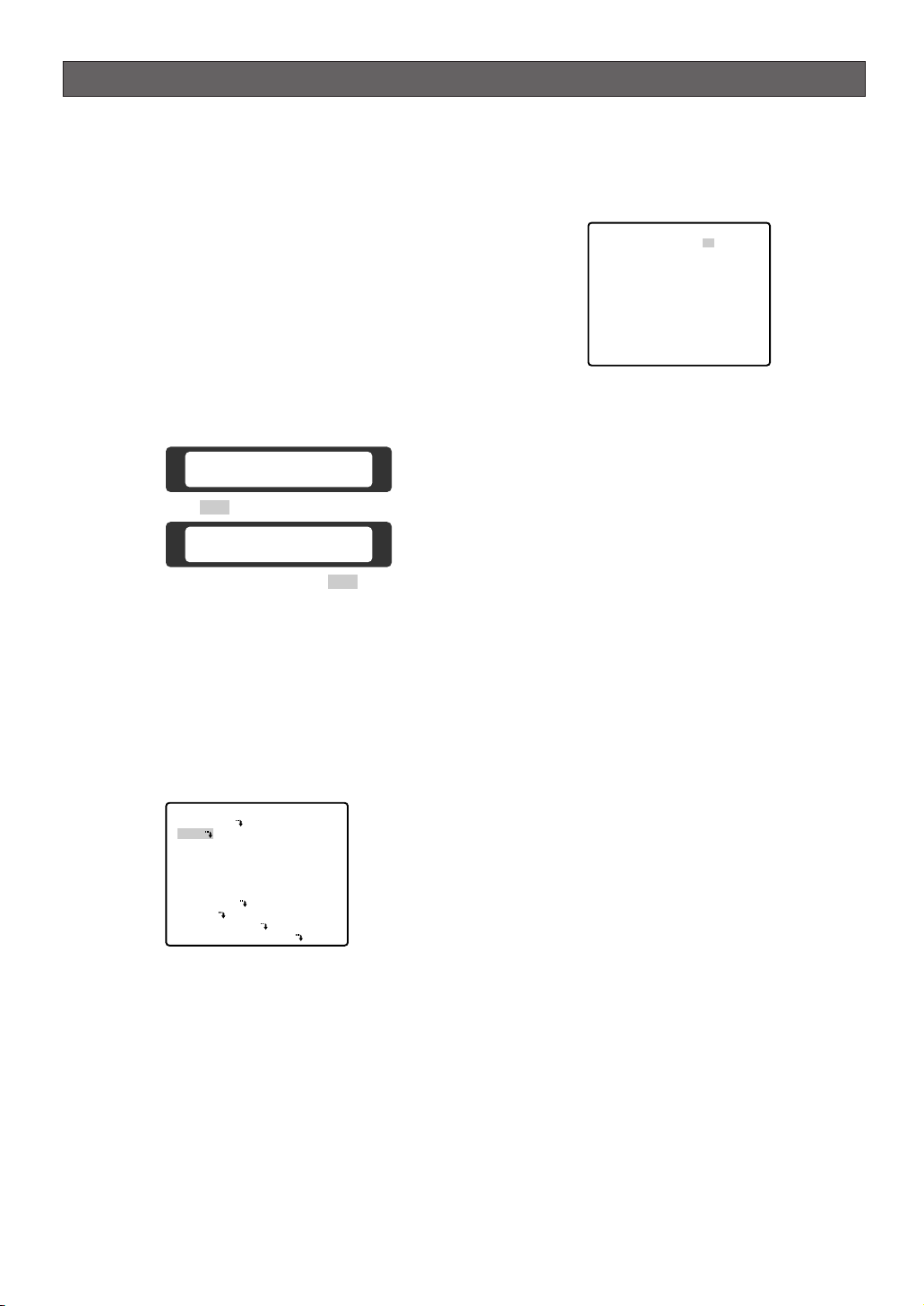
■ Menu Display
● Setup Menu Display
WV-CU550C/CJ
1. Select the number of the camera you want to set up
and a monitor to display SET UP MENU.
2. Display the D4 menu on the LCD by pressing the
appropriate direction buttons.
3. Press the F1 button.
SET UP MENU appears on the monitor.
4. To close SET UP MENU, press the F4 button.
WV-CU360C/CJ
Press the CAM SETUP key for 2 seconds or more to
open the SETUP menu.
WV-CU161C
Press the CAMERA SETUP key for 2 seconds or
more to open the SETUP menu.
WV-RM70
1. Turn the MODE SELECTION switch to the NORMAL
or ALARM OFF position.
2. Press the PROG switch for 2 seconds or more to
open the Program menu.
3. Move the cursor to Camera Set Up Menu, and press
the SET switch to open SETUP MENU.
● Submenu Display
The items marked O can be selected/changed on the
submenu.
• Move the cursor to an item with the O mark and
press the CAM (SET) key. The submenu appears.
-17-
Camera Set Up Menu
On Exit
F2 F3 F4
F1
Camera Set Up Menu
Res A.Res Exit
F1 F2 F3 F4
** RS485 SET UP **
UNIT NUMBER
SUB ADDRESS
BAUD RATE
DATA BIT
PARITY CHECK
STOP BIT
XON/XOFF
WAIT TIME
ALARM DATA
DELAY TIME
RET
1
1
19200
8
NONE
1
NOT USE
OFF
AUTO2
OFF
** SET UP MENU **
PRESET 1
MAP
HOME POSITION
SELF RETURN
AUTO MODE
AUTO PAN KEY
DIGITAL FLIP
SPECIAL1
CAMERA
RS485 SET UP
PASSWORD LOCK OFF
OFF
OFF
OFF
AUTO PAN
ON
Page 18

-18-
■ Preset Menu
● Preset Menu Display
1. Displaying the preset menu directly
(1) Move the cursor to PRESET 1
O and select the
position number with the joystick.
(2) Press the CAM (SET) key.
The preset setting menu appears on the monitor
screen.
2. Displaying the preset menu from the PRESET
NUMBER SET menu
(1) Move the cursor to MAP
O and press the CAM
(SET) key.
The PRESET NUMBER SET menu appears on the
monitor screen.
(2) Move the cursor to the position number to be set
and press the CAM (SET) key.
The preset setting menu appears on the monitor
screen. To display any position number between 33
and 64, move the cursor to "33-64" in the lower left of
the screen and press the CAM (SET) key.
Notes:
• The * mark indicates that the position number
has been preset.
• The character H refers to the home position.
• The second line from the bottom shows the
preset ID corresponding to the selected number.
"DOOR" next to "ID" in the example shown right is
for preset position number 1.
• Preset numbers 1 to 4 are linked to alarm inputs
1 to 4 respectively. If alarm input 1 comes in, the
camera turns to preset position 1, and to other
positions according to alarm input 2, 3 or 4.
● Position Setting (POSITION SET)
1. Move the cursor to POSITION SET on the preset
setting menu and press the CAM (SET) key.
The position setting menu appears.
2. To Set Panning/Tilting Positions
(1) For PAN/TILT, move the cursor to PUSH SET and
press the CAM (SET) key. The PAN/TILT setting
menu appears.
(2) Select panning/tilting positions with the joystick, and
press the CAM (SET) key.
The positions are set and the screen returns to the
position setting menu.
** SET UP MENU **
PRESET 1
MAP
HOME POSITION
SELF RETURN
AUTO MODE
AUTO PAN KEY
DIGITAL FLIP
SPECIAL1
CAMERA
RS485 SET UP
PASSWORD LOCK OFF
** SET UP MENU **
PRESET 1
MAP
HOME POSITION
SELF RETURN
AUTO MODE
AUTO PAN KEY
DIGITAL FLIP
SPECIAL1
CAMERA
RS485 SET UP
PASSWORD LOCK OFF
** PRESET NUMBER SET **
2
1*
6
5
10
9
14
13
18
17
22
21
26
25
30
29
ID:DOOR
33-64 RET
** PRESET NUMBER SET **
34
33
37
41
45
49
53
57
61
ID:
1-32 RET
38
42
46
50
54
58
62
35
39
43
47
51
55
59
63
OFF
OFF
OFF
AUTO PAN
ON
OFF
OFF
OFF
AUTO PAN
ON
3
4
7
8
11
12
15
16
19
20
23
24
27
28
31
32
36
40
44
48
52
56
60
64
PRESET NO. 1*
POSITION SET
PRESET ID
ALC/MANUAL
DWELL TIME
SCENE FILE
PRESET SPEED
RET DEL
** POSITION 1 **
PAN/TILT
ZOOM/FOCUS
U TILT D/L PAN R
PAN OFFSET SET
RET
FLOOR1
DOOR
** POSITION 1 **
PAN/TILT
ZOOM/FOCUS
PAN OFFSET SET
RET
FLOOR1
DOOR
ON
ALC
10S
1
••••••••|
L H
→
PUSH SET
→
PUSH SET
← −
→
PUSH SET
→
PUSH SET
← −
0.0
0.0
→
→
Page 19

-19-
3. Pan Offset
If the camera is replaced with a new one, the pan
offset function is used to adjust its positions to be
the same as before except patrol setting.
The system controller can download or upload the
preset position data.
Caution: The preset data for other cameras (WV-
CS654 for example) is incompatible with WVCS854B’s. WV-CS854B’s preset data will be
destroyed if you upload the conventional data. If
this happened, reset the WV-CS854B to the
default settings. Download the factory settings
into the controller and upload the correct preset
data newly to the initialized WV-CS854B.
(1) Display the PRESET NUMBER SET menu.
(2) Select a position number for the picture to be most
enlarged among the numbers with the joystick. Then
press the CAM (SET) key. The position setting menu
appears.
(3) Move the cursor to PAN OFFSET SET and select the
right or left arrow with the joystick.
(4) Press the CAM (SET) key until the desired offset
value appears.
(5) Move the cursor to an item other than PAN OFFSET
SET, and press the MON (ESC) key.
Notes:
• Further adjustment of the other positions is
unnecessary. This adjustment applies to all other
positions.
• Make sure to move the cursor before pressing
the key in step 5. Otherwise the settings will be
ignored.
• Retry the loading when the camera fails to
upload or download the data.
4. To Set the Lens Zoom and Focus Positions
(1) Move the cursor to PUSH SET for ZOOM/FOCUS
and press the CAM (SET) key. The ZOOM/FOCUS
setting menu appears.
(2) Select a zoom position by moving the zoom control
up and down and a focus position by moving the
focus control up and down, and then press the CAM
(SET) key.
The positions are set and the screen returns to the
position setting menu.
Notes:
• When the camera is used at a nearly horizontal
angle, the focus may not be adjustable to a high
level of accuracy.
• If you move the cursor to the position number
and move the joystick right or left, the position
number can be selected.
The selected preset position number can also be
set after pressing the CAM (SET) key.
• The preset and camera IDs appear in the lowerleft corner of the position setting menu after
setting them.
5. Move the cursor to RET and press the CAM (SET)
key to return to the preset setting menu.
** PRESET NUMBER SET **
2
1*
5
9
13
17
21
25
29
ID:DOOR
33-64 RET
6
10
14
18
22
26
30
3
7
11
15
19
23
27
31
4
8
12
16
20
24
28
32
** POSITION 1 **
PAN/TILT
ZOOM/FOCUS
PAN OFFSET SET
RET
FLOOR1
DOOR
→
PUSH SET
→
PUSH SET
← −
0.0
→
** POSITION 1 **
PAN/TILT
ZOOM/FOCUS
PAN OFFSET SET
RET
FLOOR1
DOOR
→
PUSH SET
→
PUSH SET
← −
0.0
→
** POSITION 1 **
PAN/TILT
ZOOM/FOCUS
U ZOOM D/L FOCUS R
PAN OFFSET SET
RET
FLOOR1
DOOR
→
PUSH SET
→
PUSH SET
← −
0.0
→
** POSITION 1 **
PAN/TILT
ZOOM/FOCUS
PAN OFFSET SET
RET
FLOOR1
DOOR
→
PUSH SET
→
PUSH SET
← −
0.0
→
Page 20

-20-
● Preset Identification Setting (PRESET
ID)
1. Move the cursor to PRESET ID on the preset setting
menu and select ON or OFF with the joystick.
The factory default setting is OFF.
ON: Preset ID appears on the monitor screen.
OFF: Preset ID does not appear.
2. Press the CAM (SET) key to display the preset ID
setting menu.
To Enter a New Preset ID
(1) Move the cursor to the desired character using
the joystick, and press the CAM (SET) key.
(2) The selected character appears in the editing
area. (The pointer in the editing area moves to
the right automatically at this moment.) To enter
a blank, select SPACE.
(3) Repeat the above procedure until all characters
are entered.
To Copy a Preset ID from Another Position
(1) Move the cursor to COPY and press the CAM
(SET) key. The preset ID in the preceding
position is immediately shown. Each
consecutive pressing of the CAM (SET) key
displays the ID preceding the one currently
displayed.
(2) Display the most prospective ID.
(3) Follow the step "To Change an Entered Preset
ID" if necessary.
To Change an Entered Preset ID
(1) Move the pointer to the character to be edited in
the editing area with the joystick.
(2) Select a new character with the joystick.
(3) Press the CAM (SET) key to determine the
Preset ID.
To Delete an Entered Preset ID
Move the cursor to RESET and press the CAM
(SET) key.
To Set a Display Position for a Preset ID
(1) Move the cursor to POSI and press the CAM
(SET) key. The display position set menu
appears.
(2) Move the ID to the desired position with the
joystick, and press the MON (ESC) key. The
display position is set and the monitor screen
returns to the preset ID setting menu.
PRESET NO. 1*
POSITION SET
PRESET ID
ALC/MANUAL
DWELL TIME
SCENE FILE
PRESET SPEED
RET DEL
Character Cursor
PRESET NO. 1*
0123456789
ABCDEFGHIJKLM
NOPQRSTUVWXYZ
().,'":;&#!?=
+-*/%$
SPACE
COPY POSI RET RESET
DOOR............
Pointer
PRESET NO. 1*
0123456789
ABCDEFGHIJKLM
NOPQRSTUVWXYZ
().,'":;&#!?=
+-*/%$
SPACE
COPY POSI RET RESET
DOOR............
ON
ALC
10S
1
••••••••|
L H
Character
Area
Command
Editing
Area
PRESET NO. 1*
0123456789
ABCDEFGHIJKLM
NOPQRSTUVWXYZ
().,'":;&#!?=
+-*/%$
SPACE
COPY POSI RET RESET
DOOR............
PRESET NO. 1*
0123456789
ABCDEFGHIJKLM
NOPQRSTUVWXYZ
().,'":;&#!?=
+-*/%$
SPACE
COPY POSI RET RESET
DOOR............
PRESET NO. 1*
0123456789
ABCDEFGHIJKLM
NOPQRSTUVWXYZ
().,'":;&#!?=
+-*/%$
SPACE
COPY POSI RET RESET
DOOR............
Page 21

-21-
To Enter the Next ID without Returning to the
Preset Setting Menu
(1) In the preset ID setting menu, move the cursor
to the top line and select a desired position
number with the joystick.
(2) Enter, copy, change or delete the ID as
described above.
To Return to the Preset Setting Menu
Move the cursor to RET and press the CAM (SET)
key.
● Light Control Setting (ALC/MANUAL)
1. Move the cursor to ALC/MANUAL and select ALC
or MANUAL with the joystick.
The factory default setting is ALC.
ALC: The lens iris is automatically adjusted to suit
the brightness of the object.
MANUAL: The lens iris is fixed at the set value
regardless of the brightness of the object.
2. In case of ALC
O
Press the CAM (SET) key. The backlight
compensation menu appears on the monitor
screen. See page 35 for the setting.
3. In case of MANUAL
O
Press the CAM (SET) key. The setting menu
appears on the monitor screen. Set the lens iris
level as desired with the joystick.
● Dwell Time (DWELL TIME)
• Move the cursor to DWELL TIME and set a dwell
time with the joystick. The factory default setting is
10S. Dwell time changes as follows:
S stands for second(s), and MIN stands for
minute(s).
● Scene File Setting (SCENE FILE)
1. To set a scene file number
Move the cursor to SCENE FILE and select a scene
file number (1 to 10, or OFF) with the joystick. The
factory default setting is 1. No scene file is selected
at OFF.
2. To set scene file details
Move the cursor to a scene file number and press
the CAM (SET) key. The setting menu appears.
FLOOR 1
DOOR
** MANUAL CONT **
IRIS
RET
••••|••••
CLOSE OPEN
PRESET NO. 1*
0123456789
ABCDEFGHIJKLM
NOPQRSTUVWXYZ
().,'":;&#!?=
+-*/%$
SPACE
COPY POSI RET RESET
DOOR............
PRESET NO. 1*
POSITION SET
PRESET ID
ALC/MANUAL
DWELL TIME
SCENE FILE
PRESET SPEED
RET DEL
ON
ALC
10S
1
••••••••|
L H
PRESET NO. 1*
POSITION SET
PRESET ID
ALC/MANUAL
DWELL TIME
SCENE FILE
PRESET SPEED
RET DEL
ON
ALC
10S
1
••••••••|
L H
PRESET NO. 1*
POSITION SET
PRESET ID
ALC/MANUAL
DWELL TIME
SCENE FILE
PRESET SPEED
RET DEL
** SCENE FILE 1 **
SHUTTER
AGC
SENS UP
WHITE BAL
MOTION DET
AF MODE
ON
ALC
10S
1
••••••••|
L H
AUTO
ON(MID)
OFF
ATW1
1
MANUAL L
RET
Page 22

-22-
See the pages below for the settings respectively.
Shutter speed: page 36
AGC: page 36
Electronic sensitivity enhancement: page 36
White balance: page 38
Motion detector: page 39
Auto focus: page 40
● Preset Speed Setting (PRESET
SPEED)
Move the cursor to PRESET SPEED and select a
speed with the joystick.
● To Return to the Preset Number Set
Menu
Move the cursor to RET and press the CAM (SET)
key. The PRESET NUMBER SET menu appears with
the * mark on the right of the preset position
number.
● To Return to the Setup Menu
Move the cursor to RET and press the CAM (SET)
key.
■ Deleting Preset Positions
1. Move the cursor to PRESET 1 and select the
position number to be deleted with the joystick.
2. Press the CAM (SET) key to display the preset
setting menu.
3. Move the cursor to DEL and press the CAM (SET)
key.
This deletes the preset position and the PRESET
NUMBER SET menu appears. The * mark on the
right of the number disappears.
Note: Your selected preset number is cancelled
only in the SEQ and SORT mode. The previously
set parameters (for PAN, TILT positions, etc.)
are not changed. If you want to change these
parameters, you must set them again.
** SET UP MENU **
PRESET 1
MAP
HOME POSITION
SELF RETURN
AUTO MODE
AUTO PAN KEY
DIGITAL FLIP
SPECIAL1
CAMERA
RS485 SET UP
PASSWORD LOCK OFF
OFF
OFF
OFF
AUTO PAN
ON
PRESET NO. 1*
POSITION SET
PRESET ID
ALC/MANUAL
DWELL TIME
SCENE FILE
PRESET SPEED
RET DEL
ON
ALC
10S
1
••••••••|
L H
PRESET NO. 1*
POSITION SET
PRESET ID
ALC/MANUAL
DWELL TIME
SCENE FILE
PRESET SPEED
RET DEL
ON
ALC
10S
1
••••••••|
L H
PRESET NO. 1*
POSITION SET
PRESET ID
ALC/MANUAL
DWELL TIME
SCENE FILE
PRESET SPEED
RET DEL
ON
ALC
10S
1
••••••••|
L H
** PRESET NUMBER SET **
2
1*
5
9
13
17
21
25
29
ID:DOOR
33-64 RET
6
10
14
18
22
26
30
3
7
11
15
19
23
27
31
4
8
12
16
20
24
28
32
** PRESET NUMBER SET **
2
1*
5
9
13
17
21
25
29
ID:DOOR
33-64 RET
6
10
14
18
22
26
30
3
7
11
15
19
23
27
31
4
8
12
16
20
24
28
32
Page 23

-23-
■ Home Position Setting (HOME
POSITION)
1. To set a position number for the home position
Move the cursor to HOME POSITION and select a
desired position number with the joystick.
2. Select OFF if you are not using the home position
function.
■ Self Return Setting (SELF
RETURN)
You can set a return time and one of operation modes
with this menu.
1. Move the cursor to SELF RETURN, select a return
time from among the following with the joystick and
press the CAM (SET) key to confirm your selection.
MIN stands for minute(s).
2. Select an operation from among the following with
the joystick and press the CAM (SET) key to confirm
your selection.
■ Auto Mode Selection (AUTO
MODE)
1. To set auto mode
Move the cursor to AUTO MODE and select a mode
with the joystick. Modes change as follows:
2. When AUTO PAN is selected, set details as follows:
Move the cursor to AUTO PAN
O and press the
CAM (SET) key to display the AUTO PAN setting
menu.
3. To set a panning starting point and panning
endpoint
Follow the steps below.
(1) Move the cursor to POSITION and press the
CAM (SET) key. The cursor moves to START.
(2) Move the joystick to select a panning starting
point and press the CAM (SET) key.
** SET UP MENU **
PRESET 1
MAP
HOME POSITION
SELF RETURN
AUTO MODE
AUTO PAN KEY
DIGITAL FLIP
SPECIAL1
CAMERA
RS485 SET UP
PASSWORD LOCK OFF
15
OFF
OFF
AUTO PAN
ON
** SET UP MENU **
PRESET 1
MAP
HOME POSITION
SELF RETURN
AUTO MODE
AUTO PAN KEY
DIGITAL FLIP
SPECIAL1
CAMERA
RS485 SET UP
PASSWORD LOCK OFF
OFF
OFF
AUTO PAN
AUTO PAN
ON
** SET UP MENU **
PRESET 1
MAP
HOME POSITION
SELF RETURN
AUTO MODE
AUTO PAN KEY
DIGITAL FLIP
SPECIAL1
CAMERA
RS485 SET UP
PASSWORD LOCK OFF
1MIN
2MIN 3MIN 5MIN 10MIN
OFF
60MIN
** SET UP MENU **
PRESET 1
MAP
HOME POSITION
SELF RETURN
AUTO MODE
AUTO PAN KEY
DIGITAL FLIP
SPECIAL1
CAMERA
RS485 SET UP
PASSWORD LOCK OFF
1
OFF
OFF
AUTO PAN
ON
30MIN 20MIN
1
10MIN AT
OFF
AUTO PAN
ON
OFF SEQ SORT AUTO PAN PATROL
** AUTO PAN **
POSITION
SPEED
ENDLESS
DWELL TIME
PAN LIMIT
ZOOM LIMIT
RET
** AUTO PAN **
POSITION
SPEED
ENDLESS
DWELL TIME
PAN LIMIT
ZOOM LIMIT
RET
START
END
••••|••••
L H
OFF
1S
OFF
OFF
START
END
••••|••••
L H
OFF
1S
OFF
OFF
OFF
AT HP AP SQ
PT
SR
Page 24

-24-
This determines the starting point and the cursor
moves to END.
(3) Move the joystick to select a panning endpoint
and press the CAM (SET) key.
This determines the endpoint and the cursor
moves to POSITION.
4. To set a panning speed
Move the cursor to SPEED, and set a panning
speed with the joystick.
The panning speed increases when the joystick is
moved to the right, and decreases when it is moved
to the left.
Caution: If the panning range is changed after the
camera has not panned for a long time or has been
panning in the same panning range, the picture may
not be clear or noise may appear. In such cases,
pan the camera fully several times.
If this does not eliminate the problem, refer servicing
to qualified service personnel.
5. To set ENDLESS to ON/OFF
Move the cursor to ENDLESS, and select ON or OFF
with the joystick.
ON: The camera pans from the starting point to the
endpoint, and keeps rotating in the same
direction to return to the starting point. Set PAN
LIMIT to OFF before ENDLESS is set to ON.
OFF: The camera pans from the starting point to
the endpoint, and rotates backward to the
starting point.
This movement is repeated over and over.
6. To set a dwell time
Move the cursor to DWELL TIME and select a dwell
time with the joystick.
Dwell time changes as follows:
7. To set pan limit ON/OFF
Move the cursor to PAN LIMIT and select ON or
OFF with the joystick.
The factory default setting is OFF.
ON: Manual pan is limited from the starting point to
the endpoint specified by position setting. Set
ENDLESS to OFF before PAN LIMIT is set to ON.
OFF: Manual pan is not limited.
Note: When ON is selected for PAN LIMIT, manual
pan moves the camera away from the other side
(PAN LIMIT) of the start-end range.
8. To set zoom limit ON/OFF
Move the cursor to ZOOM LIMIT and select ON or
OFF with the joystick.
ON: Limits the manual zoom operation by following
the procedure below.
(1) Move the cursor to ZOOM LIMIT, select ON and
press the CAM (SET) key.
The ZOOM LIMIT setting menu appears.
** AUTO PAN **
POSITION
SPEED
ENDLESS
DWELL TIME
PAN LIMIT
ZOOM LIMIT
RET
START
END
••••|••••
L H
OFF
1S
OFF
OFF
** AUTO PAN **
POSITION
SPEED
ENDLESS
DWELL TIME
PAN LIMIT
ZOOM LIMIT
RET
START
END
••••|••••
L H
OFF
1S
OFF
OFF
** AUTO PAN **
POSITION
SPEED
ENDLESS
DWELL TIME
PAN LIMIT
ZOOM LIMIT
RET
START
END
••••|••••
L H
OFF
1S
OFF
OFF
0S
1S
2S 3S
30S 5S10S20S
** ZOOM LIMIT **
ZOOM
→PUSH SET
** AUTO PAN **
POSITION
SPEED
ENDLESS
DWELL TIME
PAN LIMIT
ZOOM LIMIT
RET
START
END
••••|••••
L H
ON
1S
OFF
OFF
RET
Page 25

-25-
(2) Move the cursor to ZOOM, press the CAM (SET)
key, move the joystick to settle the ZOOM
position and return to the AUTO PAN menu. The
manual zoom operation is not available in the
TELE direction beyond the settled zoom
position.
OFF: Does not limit the manual zoom operation.
Notes:
• When the panning, tilting, zooming or focusing
in the SEQ, SORT or PATROL mode is controlled
manually, the auto mode function should be
cancelled.
To activate the auto mode, select the desired
auto mode again or set a time for SELF RETURN
in the SET UP menu.
• When 0S is selected, the camera stops without
dwelling and starts.
• Auto refreshing may be activated during the
patrol play or the auto mode to calibrate the lens
position.
■ Auto Pan Key Setting (AUTO PAN
KEY)
This is used for assigning one of the following auto
functions to the AUTO key on the controller. Pressing
the AUTO key activates the assigned function after this
setting.
• Move the cursor to AUTO PAN KEY and select an
auto function with the joystick.
The factory default setting is AUTO PAN.
The mode changes as follows:
AUTO PAN: Assigns the auto panning function to
the key.
SEQ: assigns the SEQUENCE function to the key.
SORT: assigns the SORT function to the key.
PATROL: assigns the PATROL PLAY function to the
key.
Note: AUTO PAN LED on the controller does not
light if something other than AUTO PAN is
assigned. AUTO PAN does not stop with the
AUTO PAN key.
If PASSWORD LOCK is set to ON, you cannot
operate AUTO PAN, SEQ, SORT, and PATROL
even by pressing the AUTO key.
■ Digital Flip Setting (DIGITAL FLIP)
• Move the cursor to DIGITAL FLIP and select ON or
OFF with the joystick.
OFF: The tilt range is limited from 0 ° to 90°.
ON: The digital flip function allows the tilt angle to
widen up to 180 °. The image on the monitor
screen is flipped horizontally and vertically at the
tilt angle of approx. 135 ° (If the camera is
installed on a ceiling).
Note: The tilt range narrows from 0 ° to 90 ° if PAN
LIMIT is set to ON.
Notes:
• Digital flip functions while moving the joystick
downwards. In case of moving the joystick to other
directions, it does not function.
• When OFF is selected for DIGITAL FLIP, the
following operations are required to move the
camera 180 ° vertically.
1) Move the joystick downwards to aim the camera
down.
2) Move the joystick to the right or left to rotate the
camera 180 ° horizontally.
3) Move the joystick upwards.
• To set the preset position directly from WV-CU360
System Controller, it is temporarily required to set
both the electronic zoom function and digital flip
function to OFF.
Tilt range setting is disabled between 90 ° and 185°.
** ZOOM LIMIT **
ZOOM
U ZOOM D
RET
PUSH SET
→
** SET UP MENU **
PRESET 1
MAP
HOME POSITION
SELF RETURN
AUTO MODE
AUTO PAN KEY
DIGITAL FLIP
SPECIAL1
CAMERA
RS485 SET UP
PASSWORD LOCK OFF
SEQ SORT PATROL
AUTO PAN
OFF
OFF
OFF
AUTO PAN
ON
** SET UP MENU **
PRESET 1
MAP
HOME POSITION
SELF RETURN
AUTO MODE
AUTO PAN KEY
DIGITAL FLIP
SPECIAL1
CAMERA
RS485 SET UP
PASSWORD LOCK OFF
OFF
OFF
OFF
AUTO PAN
ON
Page 26

-26-
● Password Lock (PASSWORD LOCK)
Caution: For security, do not operate your VCR for
recording while the password menus are displayed
on the monitor.
A 3-digit number is used for a password to limit
access to all settings.
1. Move the cursor to PASSWORD LOCK, then select
ON or OFF with the joystick.
Note: ON or OFF can be selected only after going
through the password verification.
OFF: You can change all settings.
ON: You cannot change settings at all nor operate
AUTO PAN, SEQ, SORT, and PATROL.
2. Press the CAM (SET) key.
Password Verification
3. The password verification menu appears.
3-1 Select a numeral for the first digit with the
joystick, and press the CAM (SET) key. Though
the entered password is not displayed, the uparrow moves one character to the right.
3-2 Repeat the above step for the 2nd and 3rd
digits.
Default: 123
3-3 The cursor moves to OK after all the three digits
have been entered. Unless you want to change
the password, press the CAM (SET) key.
If the correct password is entered, the screen
returns to SET UP MENU. ON and OFF settings
are the same as made on the SET UP MENU
menu is as set in step 1.
If a wrong password is entered, the screen
returns to the verification menu. Repeat steps 3-1
to 3-3 to verify the password.
3-4 To cancel an incomplete password, move the
cursor to RESET, and press the CAM (SET) key.
The screen returns to the verification menu.
3-5 To return to the SET UP MENU menu without
verifying the password, move the cursor to RET,
and press the CAM (SET) key.
New Password
4. To change the password in step 3-3 above, move
the cursor from OK to NEW PASSWORD, then press
the CAM (SET) key. NEW PASSWORD menu
appears.
Note: The NEW PASSWORD menu is accessible
only after the verification has been completed.
The up-arrow mark appears indicating the first digit
on the first line.
4-1 Enter a new three-digit password in the same
way as in steps 3-1 to 3-2.
4-2 The cursor moves to OK after all the three digits
have been entered. Press the CAM (SET) key to
move the cursor to the first digit on the second
line.
4-3 Enter the same password as the one you have
entered on the first line.
4-4 The cursor moves to OK. Press the CAM (SET)
key. If the new password is successfully
entered, the screen returns to SET UP MENU.
4-5 Retry steps 4-1 to 4-4. If the first entry for the
password is different from the second one, the
screen returns to the NEW PASSWORD? menu.
4-6 To return to the SET UP MENU menu without
changing the password, move the cursor to
RET, and press the CAM (SET) key.
** SET UP MENU **
PRESET 1
MAP
HOME POSITION
SELF RETURN
AUTO MODE
AUTO PAN KEY
DIGITAL FLIP
SPECIAL1
CAMERA
RS485 SET UP
PASSWORD LOCK ON
** PASSWORD? **
0 1 2 3 4 5 6 7 8 9
. . .
OK RESET
NEW PASSWORD
RET
↑
OFF
OFF
OFF
AUTO PAN
ON
** NEW PASSWORD? **
0 1 2 3 4 5 6 7 8 9
. . .
. . .
OK RESET
RET
↑
Page 27

-27-
■ Special 1 Menu Setting
(SPECIAL 1)
● Privacy Zone (PRIVACY ZONE)
Up to 8 unwanted zones can be masked on the
monitor screen.
1. Move the cursor to PRIVACY ZONE and select ON
or OFF with the joystick. Press the CAM (SET) key
to display the ZONE NUMBER setting menu.
ON: Preset privacy zones are veiled on the monitor
screen.
OFF: The veiling function does not work.
2. Select a zone number with the joystick, and press
the CAM (SET) key.
• A zone number followed by * (asterisk) indicates
that the zone has already been registered.
• When a zone number having no * is selected, the
picture is zoomed out fully.
• When a registered zone number is selected, the
camera moves to the preset position. Note that if
you move PAN/TILT, ZOOM/FOCUS or ZONE
SCALE in that position, the registered zone number
having "*" is cancelled.
• The zone frame appears in the center of the screen
if 3 or fewer mask areas exist in that picture and if
the zone number is not registered yet.
• The privacy zone may appear on the monitor
screen depending on the direction of the camera.
• The privacy zone function will not work at start-up
immediately after turning the power on.
3. To register a new zone
3-1 For PAN/TILT, move the cursor to PUSH SET
and press the CAM (SET) key.
3-2 Adjust the pan and tilt position so that the
desired position comes into the zone frame with
the joystick.
3-3 For ZOOM/FOCUS, move the cursor to PUSH
SET , and press the CAM (SET) key.
3-4 Adjust zoom and focus, and press the CAM
(SET) key.
Zoom can be adjusted within the range of 1 to
10 magnifications.
3-5 Move the cursor to ZONE SCALE, and move the
joystick to the right or left to adjust the zone
frame. Press the CAM (SET) key after the
adjustment.
** SPECIAL 1 **
PRIVACY ZONE OFF
PROPO.P/T ON
AREA TITLE ON(USER)
PATROL STOP
ALARM IN/OUT
CLEANING OFF
EL-ZOOM ON
PRESET ALM OFF
IMAGE HOLD OFF
TILT ANGLE 0°
RET
** ZONE NUMBER 1*/8 **
RET
** ZONE NUMBER 1*/8 **
PAN/TILT →PUSH SET
ZOOM/FOCUS →PUSH SET
ZONE SCALE ••••|••••
SET DEL L H
RET
** ZONE NUMBER 3*/8 **
PAN/TILT →PUSH SET
ZOOM/FOCUS →PUSH SET
ZONE SCALE ••••|••••
SET DEL L H
RET
** ZONE NUMBER 3*/8 **
PAN/TILT →PUSH SET
ZOOM/FOCUS →PUSH SET
U TILT D/L PAN R
ZONE SCALE ••••|••••
SET DEL L H
RET
** ZONE NUMBER 3*/8 **
PAN/TILT →PUSH SET
ZOOM/FOCUS →PUSH SET
U ZOOM D/L FOCUS R
ZONE SCALE ••••|••••
SET DEL L H
RET
Page 28

-28-
Moving the joystick in the L direction decreases
the zone frame, and moving it in the H direction
increases it. However, the aspect ratio is fixed at
3 to 4.
The privacy zone setting has been completed.
The menu returns to the ZONE NUMBER setting
menu. If DEL is selected, zone setting is
released and the ZONE NUMBER setting menu
appears.
3-6
• To complete new settings and repeat other
settings, move the cursor to SET and press the
CAM (SET) key. The ZONE NUMBER setting
menu reappears.
• To cancel new settings and return to the
SPECIAL 1 menu, move the cursor to DEL and
press the CAM (SET) key. New settings are not
registered.
• To complete new settings and return to the
SPECIAL 1 menu, move the cursor to RET and
press the CAM (SET) key.
● Proportional Pan/Tilt (PROPO. P/T)
• Move the cursor to PROPO. P/T and select either
ON or OFF with the joystick.
Factory default setting: ON
ON: Pan/tilt speed is in inverse proportion to the
zoom ratio as follows:
Zoom ratio Speed level
x1 7 (fastest)
x2 5
x4 3
x8 1
x15 or more 0 (slowest)
* The speed level values are approximate.
OFF: The speed is constant at the fastest level
regardless of the zoom ratio.
● Area Title (AREA TITLE)
Up to 8 area titles can be added in specific positions.
1. Select ON (NESW), ON (USER) or OFF with the
joystick.
ON (NESW): An area title is displayed for indicating
the camera direction: North (N), North-East (NE),
East (E), South-East (SE), South (S), South-West
(SW), West (W) and North-West (NW).
ON (USER): A user customized area title appears
in a maximum of 16 characters.
OFF: Area tittle does not appear.
Factory default setting: OFF
2. Press the CAM (SET) key. A submenu appears
except when OFF is selected.
Settings for ON (NESW)
1. Move the cursor to PUSH SET for PAN/TILT, and
press the CAM (SET) key. PAN/TILT is highlighted
and "U TILT D/L PAN R" appears.
2. Turn the camera north with the joystick, and press
the CAM (SET) key. The origin of the direction
(North) is set.
Note: Area titles are highlighted until the origin is
set.
** ZONE NUMBER 3*/8 **
PAN/TILT →PUSH SET
ZOOM/FOCUS →PUSH SET
ZONE SCALE ••••|••••
SET DEL L H
RET
** SPECIAL 1 **
PRIVACY ZONE OFF
PROPO.P/T ON
AREA TITLE ON(USER)
PATROL STOP
ALARM IN/OUT
CLEANING OFF
EL-ZOOM ON
PRESET ALM OFF
IMAGE HOLD OFF
TILT ANGLE 0°
RET
** SPECIAL 1 **
PRIVACY ZONE OFF
PROPO.P/T ON
AREA TITLE ON(USER)
PATROL STOP
ALARM IN/OUT
CLEANING OFF
EL-ZOOM ON
PRESET ALM OFF
IMAGE HOLD OFF
TILT ANGLE 0°
RET
** DIRECTION(NESW) **
PAN/TILT
ZOOM/FOCUS
POSI
+
N
RET
** DIRECTION(NESW) **
PAN/TILT
ZOOM/FOCUS
POSI
U TILT D/L PAN R
+
N
→
PUSH SET
→
PUSH SET
→
PUSH SET
→
PUSH SET
→
PUSH SET
RET
Page 29

-29-
3. Move the cursor to PUSH SET for ZOOM/FOCUS,
and press the CAM (SET) key. ZOOM/FOCUS is
highlighted and "U ZOOM D/L FOCUS R" appears.
4. Adjust the zoom or focus with the joystick.
5. Move the cursor to POSI
O, and press the CAM
(SET) key. The area title position appears on the
monitor screen. If needed, change the display
position with the joystick, and press the MON (ESC)
key.
An area title always appears under the camera ID.
If the camera ID and an area title are set to be
shown in separate positions, the area title appears
above the camera ID.
6. Move the cursor to RET, and press the CAM (SET)
key. The SPECIAL 1 menu appears again.
Setting for ON (USER)
If ON (USER) is selected on the SPECIAL 1 menu,
the AREA TITLE (USER) menu appears. The screen
has a number column and title column above RET
and RESET.
Note: An area number followed by an asterisk * has
already been preset.
1. To select a camera direction, move the cursor to the
desired number, and press the CAM (SET) key. The
direction menu of the selected number appears.
2. Adjust PAN/TILT, ZOOM/FOCUS and display the
position in the same way as AREA TITLE,
DIRECTION (NESW). See page 28.
3. To add a user-customized title, move the cursor to
the title of the desired number, and press the CAM
(SET) key. The AREA TITLE menu of the selected
number appears.
Area Title Editing
1. Move the cursor to the desired character in the
character field with the joystick, and press the CAM
(SET) key.
2. The selected character appears in the editing field
and the blinking cursor moves one position to the
right.
3. Repeat steps 1 and 2 until one area title is
completed.
4. Move the cursor to POSI
O, and press the CAM
(SET) key. The area title appears on the monitor
screen. If needed, change the display position with
the joystick, and press the MON (ESC) key.
** DIRECTION(NESW) **
PAN/TILT
ZOOM/FOCUS
POSI
U ZOOM D/L FOCUS R
+
N
RET
→
PUSH SET
→
PUSH SET
** AREA TITLE(USER) **
1*
NORTH
2
3 EAST
4 SOUTH-EAST
5 SOUTH
6 SOUTH-WEST
7
8 NORTH-WEST
RET RESET
FLOOR 1
N
** SPECIAL 1 **
PRIVACY ZONE OFF
PROPO.P/T ON
AREA TITLE ON(USER)
PATROL STOP
ALARM IN/OUT
CLEANING OFF
EL-ZOOM ON
PRESET ALM OFF
IMAGE HOLD OFF
TILT ANGLE 0°
RET
** DIRECTION(USER) 1 **
PAN/TILT
ZOOM/FOCUS
+
NORTH
RET DEL
→
PUSH SET
→
PUSH SET
AREA TITLE 1*
0123456789
ABCDEFGHIJKLM
NOPQRSTUVWXYZ
().,'":;&#!?=
+-*/%$
SPACE
POSI RET RESET
................
Page 30

-30-
To Quit Editing
• To return to the AREA TITLE menu, move the cursor
to RET, and press the CAM (SET) key.
• To cancel one area title, move the cursor to RESET
in the AREA TITLE menu, and press the CAM (SET)
key.
• To return to the SPECIAL 1 menu, move the cursor
to RET, and press the CAM (SET) key.
• To erase all the area titles, move the cursor to
RESET in the AREA TITLE (USER) selection menu,
and press the CAM (SET) key.
Notes:
• An area title appears under the camera ID if
both are set in the same position. If the setting is
different, they appear in the area title position.
• In case of sharing a common subject in a scene
of other camera number, the nearest area title
appears while the camera direction deviates
within 45 ° from the set position. If two or more
area numbers are set in the same position, the
title of the highest number appears.
● Patrol-learn and Patrol Play (PATROL)
A routine of manual operations can be stored for 1
minute at the maximum and reproduced repetitively.
PATROL
1. Set the following parameters for the patrol-learn
starting position. These parameters are stored
when the patrol-learn mode starts.
• PAN/TILT/ZOOM/FOCUS
• IRIS
• SHUTTER
• AGC
• SENS UP
• WHITE BALANCE
• IMAGE HOLD
• AREA TITLE
• DIGITAL FLIP
• PRIVACY ZONE
• CAMERA ID
• PROPO.PT
• PAN LIMIT
• ZOOM LIMIT
• TILT ANGLE
• BURST
• CLEANING
After starting the patrol-learn, the following manual
operations are stored.
• PAN/TILT/ZOOM/FOCUS operation
• IRIS operation
• Preset positioning
2. Open the SET UP menu and move the cursor to
SPECIAL 1. For PATROL, select LEARN, PLAY or
STOP with the joystick.
The factory default setting is STOP.
LEARN: A series of manual operations is stored.
PLAY: Stored operations are reproduced.
STOP: LEARN or PLAY is not activated.
PATROL LEARN with a Controller Having PATROL
Key
1. Press the PATROL key and the CAM (SET) key
simultaneously to start patrol-learn. The setup menu
displays "LEARNING(60S)", and the starting points
are stored.
2. Operate patrol-learn manually. The operation data
is stored. The countdown to complete learning is
displayed.
3. To stop patrol-learn, press the PATROL STOP key.
Patrol-learn with a Controller not Having the
PATROL Key
1. Close the SET UP or SPECIAL 1 menu to start
PATROL LEARN. Starting point parameters are
stored and "LEARNING(60S)" is displayed on the
monitor.
2. Operate patrol-learn manually.
FLOOR 1
NORTH
** SPECIAL 1 **
PRIVACY ZONE OFF
PROPO.P/T ON
AREA TITLE ON(USER)
PATROL PLAY
ALARM IN/OUT
CLEANING OFF
EL-ZOOM ON
PRESET ALM OFF
IMAGE HOLD OFF
TILT ANGLE 0°
RET
LEARNING(60S)
Page 31

-31-
3. Open the SET UP menu to stop learning.
Notes:
• It is recommended to set PAN LIMIT to ON for
patrol-learn. Otherwise PAN LIMIT is invalid in
playback.
• If the power fails in the patrol-learn mode, start
the patrol-learn function again from the starting
point.
• LEARN also stops 1 minute after starting if the
memory is full.
• Auto refreshing may be activated in the patrol
play mode or the auto mode to calibrate the lens
position.
Patrol Play with a Controller Having the PATROL
Key
1. Press the PATROL PLAY key. The camera turns to
the starting point and reproduces the operations
stored in the memory. Iris operation is valid only in
the playback mode.
2. Press the PATROL STOP key and PROGRAM key
simultaneously to stop playback or press any
manual operation key (e.g., PAN/TILT/
ZOOM/FOCUS) except the iris keys.
Patrol Play with a Controller not Having the PATROL
Key
1. Select patrol play in the setup menu, and then close
the menu. The camera turns to the starting point and
the operations stored in memory are reproduced.
Iris operation is valid only in the playback mode.
2. Open the SET UP menu, or press any of manual
operation keys (e.g., PAN/TILT/ ZOOM/FOCUS)
except the iris keys to stop playback.
Patrol Play with the AUTO PAN Key
1. If the PATROL PLAY function is assigned to the
AUTO PAN key, press the AUTO PAN key to turn the
camera back to the starting point and to reproduce
the operation data stored in the memory.
2. To stop playback, press the PATROL STOP key or
any manual operation key (e.g., PAN/ TILT/ ZOOM/
FOCUS) except the iris keys.
Notes:
• In the patrol play mode, the camera movement may
occasionally deviate from the entered routine when
the routine includes a move to a preset position. If
this happens, re-enter the routine of manual
operations for patrol-learn.
• In the patrol play mode, black and white automatic
switching does not work.
• In the patrol play mode, when the power of the
controller is turned on or off, the patrol play stops. In
this case, press the PATROL PLAY key again. (If
SELF RETURN is set to ON, the patrol play will start
again after elapsing the setting return time.)
● Alarm Input/Output (ALARM IN/OUT)
Move the cursor to ALARM IN/OUT, and press the CAM
(SET) key. The ALARM IN/OUT submenu appears.
Note: While the camera is in the AF mode or the lens
moves between WIDE and TELE, alarm input may
be ignored if several alarm inputs are received in
succession.
ALARM IN 1-4
Alarm input signals are supplied from external devices
through the ALARM IN connector to turn the camera to
a preset position.
1. Move the cursor to ALARM IN 1* and select a preset
position or OFF with the joystick, then press the
CAM (SET) key.
The factory default setting is OFF.
* Set ALARM IN 2, 3 and 4 in the same way as
ALARM IN 1.
1 POSI, 2 POSI, 3 POSI and 4 POSI: Preset
position. If an alarm input is received, the
camera turns to a preset position, and sends an
alarm output signal. The position number
corresponds to the alarm input number (1-1, 2-2,
3-3 and 4-4).
B/W: Available for ALARM INPUT 4 only. The
camera changes its mode from color to black
and white if ALARM IN 4 is supplied.
OFF: The camera ignores alarm inputs.
** SPECIAL 1 **
PRIVACY ZONE OFF
PROPO.P/T ON
AREA TITLE ON(USER)
PATROL STOP
ALARM IN/OUT
CLEANING OFF
EL-ZOOM ON
PRESET ALM OFF
IMAGE HOLD OFF
TILT ANGLE 0°
RET
** ALARM IN/OUT **
ALARM IN 1
ALARM IN 2
ALARM IN 3
ALARM IN 4
CNT-CLS 1
TIME OUT
CNT-CLS 2
COAX ALM OUT
RET
OFF
OFF
OFF
OFF
OFF
100MS
OFF
OFF
Page 32

-32-
CNT-CLS 1, 2 (Output)
Two contact closure signals (Open collector type) are
output through the Alarm Output connector.
1. Move the cursor to CNT-CLS 1, and select OFF,
ALARM or AUX 1 with the joystick.
The factory default setting is OFF.
When ALARM is selected, TIME OUT appears.
Select an appropriate duration from among 100 MS,
200 MS, 1000 MS (1 s), 2000 MS (2 s) and 4000 MS
(4 s) with the joystick.
The factory default setting is 100 MS.
Note: The shorter the duration, the more frequent
will be the detection output.
2. Move the cursor to CNT-CLS 2, then select OFF,
B/W or AUX 2 with the joystick.
The factory default setting is OFF.
OFF: Contact closure signals are deactivated.
ALARM: Available for CNT-CLS 1 only. A motion
detection signal is output.
AUX 1(2): An alarm signal is output when the
camera receives a command from the controller.
B/W: Available for CNT-CLS 2 only. ON (active) is
output when the camera operates in the black
and white mode if ALARM IN 4 is set to B/W.
Note: It is recommended to set the connected
external device to ignore the shorter alarm
outputs of 90 ms or less from the camera.
COAXIAL ALARM OUT
Alarm output signals are supplied through the coaxial
cable.
1. Move the cursor to COAX ALM OUT and select ON
or OFF.
2. Press the CAM (SET) key.
The factory default setting is OFF.
ON: The camera sends an alarm output signal after
it turns to a preset position.
OFF: The camera does not send an output signal.
Notes:
• The camera ignores alarm inputs during manual
operation.
• Select OFF when the camera downloads or
uploads the preset data.
● Cleaning (CLEANING)
With CLEANING in the ON position, the camera’s builtin electromechanical contacts are cleaned at regular
intervals (approx. every 7 days).
A dry contact adversely affects picture quality and
motors operation.
1. Move the cursor to CLEANING and select ON or
OFF with the joystick.
ON: The contacts are cleaned for approx. 1 minute.
"CLEANING" disappears when the cleaning
process is completed.
OFF: No contact cleaning.
Note: Select OFF when the camera downloads or
uploads the preset data.
● Electronic Zoom (EL-ZOOM)
The electronic zoom magnifies a scene 10-fold. With a
22-fold optical zoom lens, the camera is capable of
220-fold zoom.
1. Move the cursor to EL-ZOOM and select ON or OFF
with the joystick, and then press the CAM (SET) key.
** SPECIAL 1 **
PRIVACY ZONE OFF
PROPO.P/T ON
AREA TITLE ON(USER)
PATROL STOP
ALARM IN/OUT
CLEANING ON
EL-ZOOM ON
PRESET ALM OFF
IMAGE HOLD OFF
TILT ANGLE 0°
RET
CLEANING
** SPECIAL 1 **
PRIVACY ZONE OFF
PROPO.P/T ON
AREA TITLE ON(USER)
PATROL STOP
ALARM IN/OUT
CLEANING ON
EL-ZOOM ON
PRESET ALM OFF
IMAGE HOLD OFF
TILT ANGLE 0°
RET
Page 33

-33-
ON: 10 - fold electronic zoom is available with the
ZOOM switch on the controller.
OFF: The electronic zoom function is not used.
Notes:
• A scene magnified by the electronic zoom
function may be inferior in picture quality to a
non-magnified one.
• The electronic zoom does not function in the
preset position setting mode.
• To set preset positions directly from WV-CU360
System Controller, you need to set the electronic
zoom function temporarily to OFF.
● Preset Alarm (PRESET ALM)
An alarm output is sent when the camera moves to the
designated position depending on the mode.
1. Move the cursor to PRESET ALARM and select ON
or OFF.
ON: Alarm signals are output in the following cases.
• When a preset positioning sequence is
completed while AUTO MODE is set to SEQ.
• When a preset positioning sequence is
completed while AUTO MODE is set to SORT.
• When the self-return function has returned the
camera to its home position.
• Positioning is completed for a position request
command.
• Positioning to the designated point is completed
for ALARM IN/OUT.
• When positioning to the starting point is
completed while AUTO MODE is set to AUTO
PAN.
• When positioning to the starting point is
completed while PATROL is set to PLAY.
OFF: Alarm signals are not output.
Note: Select OFF when the camera downloads or
uploads the preset data.
● Image Hold (IMAGE HOLD)
The camera picture remains as a still image on the
monitor screen until the camera reaches the preset
position. This function is useful for surveillance via local
area network.
1. Move the cursor to IMAGE HOLD and select ON or
OFF.
ON: The last displayed still image is shown till the
camera finishes moving to a preset position.
However, the still image may be distorted with
the effect of panning or tilting.
OFF: The current image is being displayed while
the camera is moving to a preset position.
● Tilt Angle (TILT ANGLE 0 °/5 °)
You can select the tilting range.
1. Move the cursor to TILT ANGLE and select 0 ° or
5 °.
0 °: The tilting range is between 0° and 180 °.
5 °: The tilting range is between –5° and 185 °.
Note: When 5 ° is selected in the WIDE mode, a
subject is not displayed on approximately the
upper half of the screen or the screen becomes
white for some subjects due to the AGC effect.
** SPECIAL 1 **
PRIVACY ZONE OFF
PROPO.P/T ON
AREA TITLE ON(USER)
PATROL STOP
ALARM IN/OUT
CLEANING OFF
EL-ZOOM ON
PRESET ALM ON
IMAGE HOLD OFF
TILT ANGLE 0°
RET
** SPECIAL 1 **
PRIVACY ZONE OFF
PROPO.P/T ON
AREA TITLE ON(USER)
PATROL STOP
ALARM IN/OUT
CLEANING OFF
EL-ZOOM ON
PRESET ALM OFF
IMAGE HOLD ON
TILT ANGLE 0°
RET
** SPECIAL 1 **
PRIVACY ZONE OFF
PROPO.P/T ON
AREA TITLE ON(USER)
PATROL STOP
ALARM IN/OUT
CLEANING OFF
EL-ZOOM ON
PRESET ALM OFF
IMAGE HOLD ON
TILT ANGLE 0°
RET
Page 34

-34-
■ Camera Setting
● To Display the Camera Setting Menu
Move the cursor to CAMERA O, and press the CAM
(SET) key. The camera setting menu appears.
● Camera Identification (CAMERA ID)
1. Move the cursor to CAMERA ID, and select ON to
display the camera identification with the joystick.
2. Follow the steps below to edit the camera ID
characters.
2-1 Move the cursor to CAMERA ID and press the
CAM (SET) key to display the character editing
menu.
2-2 Move the cursor to the character you want to
edit or change with the joystick, and press the
CAM (SET) key. The selected character appears
in the editing area.
2-3 Repeat the steps above until all characters are
edited.
3. After editing the camera identification characters,
follow the steps below to decide the position of
CAMERA ID.
3-1 Move the cursor to POSI, and press the CAM
(SET) key to display the ID position menu.
3-2 Decide the position of the camera ID with the
joystick. Press the MON (ESC) key to fix the
position, and return to the character editing
menu.
Notes:
• When you want the pointer to move to a specific
character in the editing area, select a new
character, and press the CAM (SET) key. This
function allows you to edit or correct a specific
character.
• To enter a blank space into the camera ID,
move the cursor to SPACE, and press the CAM
(SET) key.
• To erase all characters in the editing area, move
the cursor to RESET, and press the CAM (SET)
key.
• The positioning of CAMERA ID stops at the
edges of the screen.
• CAMERA ID moves faster when the joystick is
kept at the right or left for one second or more.
• Move the cursor to RET to return to the SET UP
menu, and press the CAM (SET) key.
** SET UP MENU **
PRESET 1
MAP
HOME POSITION
SELF RETURN
AUTO MODE
AUTO PAN KEY
DIGITAL FLIP
SPECIAL1
CAMERA
RS485 SET UP
PASSWORD LOCK OFF
** SET UP **
CAMERA ID
ALC/MANUAL
SHUTTER
AGC
SENS UP
SYNC
WHITE BAL
MOTION DET
AF MODE
RET SPECIAL2
** SET UP **
CAMERA ID
ALC/MANUAL
SHUTTER
AGC
SENS UP
SYNC
WHITE BAL
MOTION DET
AF MODE
RET SPECIAL2
OFF
OFF
OFF
AUTO PAN
ON
OFF
ALC
AUTO
ON(MID)
OFF
INT
ATW1
OFF
AUTO L
ON
ALC
AUTO
ON(MID)
OFF
INT
ATW1
OFF
AUTO L
CAMERA ID
0123456789
ABCDEFGHIJKLM
NOPQRSTUVWXYZ
().,'":;&#!?=
+-*/%$
SPACE
POSI RET RESET
CAM1............
CAM1
CAMERA ID
0123456789
ABCDEFGHIJKLM
NOPQRSTUVWXYZ
().,'":;&#!?=
+-*/%$
SPACE
POSI RET RESET
CAM1............
CAMERA ID
0123456789
ABCDEFGHIJKLM
NOPQRSTUVWXYZ
().,'":;&#!?=
+-*/%$
SPACE
POSI RET RESET
CAM1............
Page 35

-35-
● Light Control Setting (ALC/MANUAL)
1. Move the cursor to ALC/MANUAL and select ALC
or MANUAL with the joystick. When you select ALC,
set backlight compensation.
Note: The backlight compensation submenu
associated with this menu is described
separately and should be set up after installing
the camera at the site and observing the actual
site picture.
2. When MANUAL is selected, quit the setup menu by
pressing the MON (ESC) key. Press the OPEN or
CLOSE key on the controller for iris adjustment.
(1) ALC Mode with SUPER-D2 ON
1. Press the CAM (SET) key after selecting ALC. The
ALC CONT menu appears.
2. Move the cursor to the SUPER-D2 parameter and
select ON.
3. If you want to adjust the video output level, move
the "I" cursor for LEVEL. Adjust it to the desired level
with the joystick.
4. Move the cursor to RET and press the CAM (SET)
key to return to the CAM SET UP menu. To return to
the camera picture, press the F4 button.
(2) ALC Mode with SUPER-D2 OFF
1. Move the cursor to SUPER-D2 and select OFF.
(When you select MANUAL, SUPER-D2 is not
available.) MASK SET appears on the menu.
2. Move the cursor to MASK SET and press the CAM
(SET) key. The 48 mask areas appear on the
monitor screen. The cursor is blinking in the top left
corner of the screen.
3. To mask an area where backlight is bright, move
the cursor to the area and press the CAM (SET)
key. The mask turns white. Repeat this procedure to
mask the desired areas.
4. To cancel a masked area, move the cursor to the
area, and press the CAM (SET) key. To cancel all
masking areas, press the F2 button of WV-CU550C.
For WV-RM70, press the right and left switches
simultaneously.
5. After masking is completed, press the MON (ESC)
key. The 48 mask areas on the monitor screen
disappear and the ALC CONT menu appears.
Blinking
Blinking
Blinking
Turns to white
** SET UP **
CAMERA ID
ALC/MANUAL
SHUTTER
AGC
SENS UP
SYNC
WHITE BAL
MOTION DET
AF MODE
RET SPECIAL2
OFF
ALC
AUTO
ON(MID)
OFF
INT
ATW1
OFF
AUTO L
** ALC CONT **
BACK LIGHT COMP
SUPER-D2
MASK SET
LEVEL
RET
OFF
••••|••••
- +
** ALC CONT **
BACK LIGHT COMP
SUPER-D2
LEVEL
RET
ON
••••|••••
- +
Page 36

-36-
6. If you want to change the picture contrast, move the
"I" cursor for LEVEL and adjust the level.
7. Move the cursor to RET and press the CAM (SET)
key to return to the CAM SET UP menu.
To return to the camera picture, press the F4
button.
● Shutter Speed Setting (SHUTTER)
Note: When ON is selected for SUPER-D2 on the ALC
CONT menu, only OFF and AUTO are available.
To select an electronic fixed shutter speed, select
OFF for SUPER-D2 in the menu.
Move the cursor to SHUTTER and select the
electronic shutter speed with the joystick. The
electronic shutter speed changes as follows with
the joystick:
• When OFF is selected for SUPER-D2 on the ALC
CONT menu
• In the AUTO mode, an object is clearly imaged
under highlighted conditions by using the
combination technology of iris and shutter
functions.
Note: When the selected shutter speed caused
flicker on condition that fluorescent lamps stay
on, change this setting to 'OFF'.
● Gain Control [AGC ON (LOW/ MID/
HIGH)/OFF]
Move the cursor to AGC and select ON (LOW), ON
(MID), ON (HIGH) or (OFF) with the joystick.
Notes:
• Even if AGC is set to ON and if the noise reduction
function is enabled, afterimages may be produced
by shooting a moving object or by panning or tilting
the camera.
• For more information, refer to Digital Noise
Reduction on page 41.
● Electronic Sensitivity Enhancement
(SENS UP)
Move the cursor to SENS UP and select the desired
electronic sensitivity enhancement mode with the
joystick. The electronic sensitivity enhancement mode
changes as follows with the joystick:
• When OFF is selected for SUPER-D2 on the ALC
CONT menu
** ALC CONT **
BACK LIGHT COMP
SUPER-D2
MASK SET
LEVEL
RET
OFF
••••|••••
- +
** ALC CONT **
BACK LIGHT COMP
SUPER-D2
MASK SET
LEVEL
RET
OFF
••••|••••
- +
** SET UP **
CAMERA ID
ALC/MANUAL
SHUTTER
AGC
SENS UP
SYNC
WHITE BAL
MOTION DET
AF MODE
RET SPECIAL2
OFF (1/60) 1/100AUTO
1/10 000 1/4 000 1/2 000 1/1 000
OFF
ALC
AUTO
ON(MID)
OFF
INT
ATW1
OFF
AUTO L
1/250 1/500
** SET UP **
CAMERA ID
ALC/MANUAL
SHUTTER
AGC
SENS UP
SYNC
WHITE BAL
MOTION DET
AF MODE
RET SPECIAL2
OFF
ALC
AUTO
ON(MID)
OFF
INT
ATW1
OFF
AUTO L
** SET UP **
CAMERA ID
ALC/MANUAL
SHUTTER
AGC
SENS UP
SYNC
WHITE BAL
MOTION DET
AF MODE
RET SPECIAL2
OFF
X2 AUTO
X16 AUTO
X32 AUTO X2 FIX
X6 FIX X10 FIX X16 FIX X32 FIX
OFF
ALC
AUTO
ON(MID)
OFF
INT
ATW1
OFF
AUTO L
X4 AUTO X6 AUTO X10 AUTO
X4 FIXOFF
Page 37

-37-
• When ON is selected for SUPER-D2 on the ALC
CONT menu
Notes:
• When ON is selected for SUPER-D2 in the ALC
CONT menu, FIX is not available for this item.
• When AUTO is selected for SENS UP and ON is
selected for SUPER-D2, the SENS UP function has
priority so that the SUPER-D2 function is not
activated automatically.
• While the SENS UP function is selected, noise or
spots may appear in the picture when the sensitivity
of the camera is increased. This is a normal
phenomenon.
● Synchronization (SYNC)
Move the cursor to SYNC and select LL or INT with the
joystick.
Important Notices:
1. The priorities of SYNC modes are assigned as
follows:
1. Multiplexed vertical drive (VD2) (highest priority)
2. Line-lock (LL)
3. Internal sync (INT) (lowest priority)
2. To use internal sync, select INT.
3. Whenever the vertical drive pulse (VD2) is supplied
to the camera, the camera sync mode is
automatically switched to the multiplexed vertical
drive pulse (VD2) regardless of the selected sync
mode.
Line-lock Sync Mode (LL)
1. Move the cursor to SYNC and select LL with the
joystick. The LL sync mode is not available when
the multiplexed vertical drive (VD2) pulse is
supplied.
2. After selecting LL, press the CAM (SET) key.
The SYNC menu appears on the monitor screen.
3. Supply the video output signal of the camera to be
adjusted and the reference video output signal to a
dual-trace oscilloscope.
4. Set the dual-trace oscilloscope to the vertical rate
and expand the vertical sync portion on the
oscilloscope.
5. Move the cursor to COARSE with the joystick.
6. Match the vertical phases for both video output
signals as closely as possible with the joystick. The
coarse adjustment can be performed in steps of
22.5 degrees (16 steps) with the joystick.
Note: After the 16th step, the adjustment level
returns to the first step.
7. Move the cursor to FINE by using the joystick.
OFF
X2 AUTO
X4 AUTO X6 AUTO
X10 AUTO
X32 AUTO X16 AUTO
** SET UP **
CAMERA ID
ALC/MANUAL
SHUTTER
AGC
SENS UP
SYNC
WHITE BAL
MOTION DET
AF MODE
RET SPECIAL2
OFF
ALC
AUTO
ON(MID)
OFF
LL
ATW1
OFF
AUTO L
** SET UP **
CAMERA ID
ALC/MANUAL
SHUTTER
AGC
SENS UP
SYNC
WHITE BAL
MOTION DET
AF MODE
RET SPECIAL2
OFF
ALC
AUTO
ON(MID)
OFF
INT
ATW1
OFF
AUTO L
** SYNC **
V PHASE
COARSE
FINE
RET
1(1--16)
•|•••••••
- +
1 (1 - - - 16): 0 degrees
2 (1 - - - 16): 22.5 degrees
16 (1 - - - 16): 337.5 degrees
** SYNC **
V PHASE
COARSE
FINE
RET
1(1--16)
•|•••••••
- +
Page 38

-38-
8. Match the vertical phase for both video output
signals as closely as possible with the joystick.
Notes:
• When the "|" cursor reaches the "+" end, it jumps
back to "–". At the same time, COARSE is
incremented by one step to enable a continuous
adjustment. The reverse takes place when the "|"
cursor reaches the "–" end.
• When the joystick is kept at the right or left for
one second or more, the "|" cursor moves
quickly.
• To reset COARSE and FINE to the preset values,
press the F2 button of WV-CU550C. For WVRM70, press the right and left switches
simultaneously. COARSE is preset to zerocrossing of the AC line phase.
• If the AC line phase contains spike noise, etc.,
the vertical phase of the video output signal may
be disturbed.
● White Balance (WHITE BAL)
(1) Auto-Tracing White Balance Mode (ATW1/
ATW2)
1. Move the cursor to WHITE BAL and select ATW1
with the joystick. The white balance of the camera is
automatically adjusted.
2. For fine adjustment of ATW1/ATW2, press the CAM
(SET) key. The ATW1/ATW2 fine adjustment menu
appears on the monitor screen.
3. Move the cursor to RET with the joystick and press
the CAM (SET) key to return to the SET UP menu.
(2) Automatic White Balance Control Mode (AWC)
1. Move the cursor to WHITE BAL and select AWC →
PUSH SW with the joystick.
2. Press the CAM (SET) key to start the white balance
setup. PUSH SW is highlighted to indicate that
white balance is being set.
3. PUSH SW returns to normal when balance setting is
completed.
4. For fine adjustment of the AWC, move the cursor to
AWC and press the CAM (SET) key. The AWC fine
adjustment menu appears on the monitor screen.
5. Move the cursor to RET with the joystick and press
the CAM (SET) key to return to the SET UP menu.
** SYNC **
V PHASE
COARSE
FINE
RET
** SYNC **
V PHASE
COARSE
FINE
RET
4(1--16)
••••••|••
- +
1(1--16)
•|•••••••
- +
** ATW1 **
R
B
RET
••••|••••
- +
••••|••••
- +
** SET UP **
CAMERA ID
ALC/MANUAL
SHUTTER
AGC
SENS UP
SYNC
WHITE BAL
MOTION DET
AF MODE
RET SPECIAL2
OFF
ALC
AUTO
ON(MID)
OFF
INT
AWC
→
PUSH SW
OFF
AUTO L
** AWC **
R
B
••••|••••
- +
••••|••••
- +
** SET UP **
CAMERA ID
ALC/MANUAL
SHUTTER
AGC
SENS UP
SYNC
WHITE BAL
MOTION DET
AF MODE
RET SPECIAL2
OFF
ALC
AUTO
ON(MID)
OFF
INT
ATW1
OFF
AUTO L
RET
Page 39

-39-
● Motion Detector (MOTION DET)
1. Move the cursor to MOTION DET and select ON or
OFF with the joystick.
2. If ON is selected, press the CAM (SET) key. The
MOTION DETECT menu appears.
You can mask the areas in this menu.
3. Move the cursor to MASK SET and press the CAM
(SET) key. 48 mask areas appear on the monitor
screen.
Refer to Light Control Setting on page 35 for
masking operations.
4. After masking areas, press the MON (ESC) key. The
MOTION DETECT menu appears on the monitor
screen.
5. Move the cursor to ALARM and select ON or OFF
with the joystick.
ON: The alarm signal is supplied while the display
mode is activated.
OFF: The alarm signal is not supplied while the
display mode is activated.
6. Move the cursor to DISPLAY MODE.
Press the CAM (SET) key to see the present setting.
The areas that detect the motions blink.
7. Move the cursor to LEVEL with the joystick.
Obtain the optimum detection level with the joystick.
Note: Repeat the above procedure until you obtain
the adjusted results.
8. Dwell Time
Move the cursor to DWELL TIME, and select a time
with the Joystick.
When the time specified here elapses after motion
detection, the camera will notify the connected
device of the alarm activation. The default setting is
2 seconds.
Selectable times (seconds): 2s, 5s, 10s, 30s
9. Move the cursor to RECOVER TIME with the joystick.
You can select the following recover times.
10.Move the cursor to RET and press the CAM (SET)
key to return to SET UP.
Important Notices:
• The motion detection should meet the following
conditions.
1) The picture size on the screen should be larger
than 1/48 of the actual picture size.
2) The contrast ratio between the object and the
background picture should be more than 5 % at
the maximum detection level.
3) The time that takes the object to move from one
end of the screen to the other should be more
than 0.1 second.
• Also under the following conditions, mask or adjust
the detection level to prevent malfunction.
1) When leaves, curtains, etc. are swayed by the
wind.
2) When a picture has a high noise content due to
low light conditions.
3) When the object is illuminated by lighting
equipment that constantly turns on and off.
** SET UP **
CAMERA ID
ALC/MANUAL
SHUTTER
AGC
SENS UP
SYNC
WHITE BAL
MOTION DET
AF MODE
RET SPECIAL2
OFF
ALC
AUTO
ON(MID)
OFF
INT
ATW1
ON
AUTO L
1MIN
2MIN 3MIN 5MIN 10MIN
OFF
60MIN
30MIN 20MIN
** MOTION DETECT **
LEVEL
DWELL TIME 2S
DISPLAY MODE
ALARM OFF
MASK SET
RECOVER TIME
RET
••••|••••
- +
1MIN
Page 40

-40-
• The alarm signal will take approx. 0.2 seconds to
reach the alarm terminal of the VCR after the camera
detects the object.
Because the alarm signal is multiplexed on the
video signal, it may be mistakenly interpreted by
other video equipment as a time code signal.
Therefore, when this camera is not used in a
Panasonic Intelligent CCTV System, select OFF to
prevent the above from occurring.
● Auto Focus Setting (AF MODE)
1. Move the cursor to AF MODE, and select the
following mode with the joystick. S, M and L stand
for Small, Middle and Large areas respectively in
the center of a scene that are used for sensing
sharpness in auto-focusing.
MANUAL S, M, L: Auto focus is activated only when
the AF key on the controller is pressed.
AUTO S, M, L: Auto focus is activated automatically
while the pan, tilt or zoom operation is manually
performed. These may be selected in the same
way as MANUAL by pressing the AF key on the
controller.
2. To confirm auto-focus operation, press CAM (SET)
key.
Notes:
• When the electronic sensitivity enhancement (SENS
UP) is activated except in the x2 FIX or x2 AUTO
mode, this function is automatically set to MANUAL
(S, M, L).
• The auto focus lens does not function properly in the
AUTO mode after using the WIDE lens.
• The auto focus lens may not function properly in the
AUTO mode under the following conditions.
1. Dirt or water on window glass.
The auto focus may focus on the dirt or water.
2. Low lighting or illumination.
3. Bright objects or high intensity objects.
4. Single color object such as a white wall or fine
felt
5. No center objects and sloping objects
6. Far and near objects on the screen
● Special 2 Menu (SPECIAL2)
This menu lets you adjust and set up the picture quality
to meet your requirements.
Move the cursor to SPECIAL2 and press the F2 button
of WV-CU550C. The special menu appears on the
monitor screen. For WV-RM70, hold down the right and
left switches simultaneously for 2 seconds or more.
• Chroma Level (CHROMA GAIN)
Aperture Level (AP GAIN)
Pedestal Level (PEDESTAL)
Hue Level Setting (HUE)
1. Move the cursor to CHROMA GAIN, and the "I"
cursor is highlighted.
2. Move the "I" cursor to your desired position with the
joystick and press the CAM (SET) key to confirm the
level.
Notes:
• For setting the aperture, pedestal and hue levels,
perform the same steps described above (but in the
step 1, move the cursor to AP GAIN for the aperture
level, to PEDESTAL for the pedestal level and to
HUE for the hue level.).
• To reset the settings to the factory default, press the
F2 button of WV-CU550C/CJ. (For WV-RM70, hold
down the right and left switches simultaneously for 2
seconds or more.)
• Resolution (RESOLUTION)
Move the cursor to RESOLUTION and move the
joystick to select NORMAL or HIGH.
** SET UP **
CAMERA ID
ALC/MANUAL
SHUTTER
AGC
SENS UP
SYNC
WHITE BAL
MOTION DET
AF MODE
RET SPECIAL2
AUTO S AUTO M AUTO L
MANUAL L MANUAL M MANUAL S
OFF
ALC
AUTO
ON(MID)
OFF
INT
ATW1
OFF
AUTO L
** SET UP **
CAMERA ID
ALC/MANUAL
SHUTTER
AGC
SENS UP
SYNC
WHITE BAL
MOTION DET
AF MODE
RET SPECIAL2
** SPECIAL2 **
CHROMA GAIN – +
AP GAIN – +
PEDESTAL – +
HUE –••••|••••+
RESOLUTION
DNR LOW2
BW MODE
PIX OFF
REFRESH
CAMERA RESET
RET
** SPECIAL2 **
CHROMA GAIN – +
AP GAIN – +
PEDESTAL – +
HUE –••••|••••+
RESOLUTION
DNR LOW2
BW MODE
PIX OFF
REFRESH
CAMERA RESET
RET
OFF
ALC
AUTO
ON(MID)
OFF
INT
ATW1
OFF
AUTO L
••••|••••
••••|••••
•|•••••••
NORMAL
→
PUSH SET
→
PUSH SET
••••|••••
••••|••••
•|•••••••
NORMAL
→
PUSH SET
→
PUSH SET
Page 41

-41-
NORMAL: Sets the horizontal resolution to more
than 480 lines.
HIGH: Sets the horizontal resolution to more than
510 lines.
Note: After selecting HIGH, noise may increase
when the SENS UP function is activated under
low illumination.
• Digital Noise Reduction (DNR)
DNR may be used to improve quality under low
light conditions. There are 4 levels of DNR, which
may be selected depending on local site
conditions. Factory default setting: LOW2
You may need to try different settings to find the
most suitable conditions for your application.
Move the cursor to DNR and select LOW1, LOW2,
HIGH1 or HIGH2 with the joystick.
LOW1: DNR level is low. The after-image remains.
LOW2: DNR level is low. The after-image is
reduced.
HIGH1: DNR level is high. The after-image remains.
HIGH2: DNR level is high. The after-image is
reduced.
• Black and White Mode (BW MODE)
Move the cursor to BW MODE and press the CAM
(SET) key. The BW MODE menu appears. You can
set up the BW mode on this menu.
BW Setting
1. Move the cursor to BW and select AUTO, ON or
OFF with the joystick. Factory default setting:
OFF.
AUTO: The camera selects the black and white
mode if the picture is dark, or the color mode
if the picture is bright enough.
ON: The black and white mode is selected.
OFF: The color mode is selected.
Note: Selecting the color mode is disabled if
ALARM IN 4 is set to B/W on the special 1
menu.
2. If you have selected AUTO, press the CAM (SET)
key to open the BW AUTO submenu.
3. Select HIGH or LOW for the threshold level at
which the camera automatically switches to BW
or color mode. Default: HIGH
The illuminance shown below is based on the
assumption that the camera is used in an area lit
by halogen lamps, and that AGC on the menu is
set to MID.
HIGH: approximately 6 lx
LOW: approximately 2.5 lx
Note: When near-infrared lamps are used, the
image may be displayed out of focus and
mode switching may not perform
automatically.
4. Move the I cursor to set DURATION TIME.
Default: 30 seconds
The camera determines whether to switch the
mode when the time set for holding a picture
motionless on the screen has elapsed.
Available duration times: (S) 10 s ↔ 30 s ↔ 60
s
↔ 300 s (L)
Note: A pan/tilt, zoom or focus operation will
restart after the holding time.
PIX SENS UP Setting
Move the cursor to PIX SENS UP and move the
joystick to select OFF or X2 AUTO.
X2 AUTO: Sensitivity will be automatically doubled
at the maximum in the black and white mode.
OFF: Sensitivity will not be enhanced.
Notes:
• "X2 AUTO" is not available when AGC is set to
OFF. "X2 AUTO" is automatically set to OFF.
• When the picture becomes stable, the luminance
may change for a moment.
BURST (BW) Setting
Move the cursor to BURST (BW) and select ON or
OFF with the joystick. Default: ON.
ON: The burst signal is supplied along with the
black and white composite video.
OFF: The burst signal is not output.
Note: It is recommended to select ON usually.
** SPECIAL2 **
CHROMA GAIN – +
AP GAIN – +
PEDESTAL – +
HUE –••••|••••+
RESOLUTION
DNR LOW2
BW MODE
PIX OFF
REFRESH
CAMERA RESET
RET
••••|••••
••••|••••
•|•••••••
NORMAL
→
PUSH SET
→
PUSH SET
** BW MODE **
BW OFF
PIX SENS UP OFF
BURST(BW) OFF
RET
** BW MODE **
BW AUTO
LEVEL HIGH
DURATION TIME •|••
L H
PIX SENS UP OFF
BURST(BW) OFF
RET
Page 42

-42-
• PIX OFF Setting (PIX OFF)
In this setting, you can assign a blemish position
and compensate the blemish.
1. Move the cursor to PIX OFF and press the CAM
(SET) key. The PIX OFF menu appears.
2. Select a number and press the CAM (SET) key. The
blemish compensation position setting screen
appears.
Move the joystick to place the "+" cursor on the
blemish position. After moving the "+" cursor to a
position where the blemish looks inconspicuous,
press the CAM (SET) key. Consequently, the
blemish compensation position is set up and the PIX
OFF menu is restored.
After a blemish compensation position is set up, "*"
is attached at the right of the number.
3. If you would like to delete a blemish compensation
position, move the cursor to the applicable number
and press the CAM (SET) key.
The blemish compensation position setting screen
appears. Press the F2 button of WV-CU550C/CJ
when the setting screen is active.
For WV-RM70, hold down the right and left buttons
simultaneously for 2 seconds or more.
For WV-CU360C/CJ and WV-CU161C, hold down
the [4] and [6] keys simultaneously for 2 seconds or
more.
The screen is restored to the PIX OFF menu, the
blemish compensation position is deleted and "*" is
also deleted from the right of the number.
• To Restore the Camera Default Position
(REFRESH)
Move the cursor to REFRESH with the joystick and
press the F2 button of WV-CU550C/CJ.
For WV-RM70, hold down the right and left buttons
simultaneously for 2 seconds or more.
For WV-CU360C/CJ and WV-CU161C, hold down
the [4] and [6] keys simultaneously for 2 seconds or
more.
• Camera Resetting (CAMERA RESET)
Move the cursor to CAMERA RESET with the joystick
and press the F3 button of WV-CU550C/CJ.
The camera is reset to the factory default settings.
For WV-RM70, hold down the right, left and set
switches simultaneously for 2 seconds or more. For
WV-CU360C/CJ and WV-CU161C, hold down the
[4], [5] and [6] keys simultaneously for 2 seconds or
more.
Note: In case of performing this operation on the
condition that the cursor is positioned on other
than CAMERA RESET, you cannot perform the
operations on the menu thereafter. In that event,
set the camera menu to ON again with the
controller referring to page 12.
• To Close the SPECIAL2 Menu
Move the cursor to RET and press the CAM (SET)
key.
The setup menu appears on the monitor screen.
Reset to the Factory Default Settings
Any of the above settings plus the ALC/MANUAL level
control and phase adjustments can be reset to the
factory default settings by placing the cursor over the
desired mode and then pressing the F2 button of WVCU550C/CJ.
** PIX OFF **
1* 2* 3* 4*
5* 6* 7* 8
000 000
RET
** SPECIAL2 **
CHROMA GAIN – +
AP GAIN – +
PEDESTAL – +
HUE –••••
RESOLUTION
DNR LOW2
BW MODE
PIX OFF
REFRESH
CAMERA RESET
RET
••••|••••
••••|••••
•|•••••••
|
••••+
NORMAL
→
PUSH SET
→
PUSH SET
+
** SPECIAL2 **
CHROMA GAIN – +
AP GAIN – +
PEDESTAL – +
HUE –••••|••••+
RESOLUTION
DNR LOW2
BW MODE
PIX OFF
REFRESH
CAMERA RESET
RET
••••|••••
••••|••••
•|•••••••
NORMAL
→
PUSH SET
→
PUSH SET
** SPECIAL2 **
CHROMA GAIN – +
AP GAIN – +
PEDESTAL – +
HUE –••••|••••+
RESOLUTION
DNR LOW2
BW MODE
PIX OFF
REFRESH
CAMERA RESET
RET
••••|••••
••••|••••
•|•••••••
NORMAL
→
PUSH SET
→
PUSH SET
Page 43

-43-
For WV-RM70, hold down the right and left switches
simultaneously for 2 seconds or more.
For WV-CU360C/CJ and WV-CU161C, hold down the
[4] and [6] keys simultaneously for 2 seconds or more.
■ RS485 Setup
● Initial Camera Communication
Parameters
In an RS485 chain, the matrix switcher, PC, controllers
and cameras should be set to the same protocol and
parameters for communication. Confirm the system
protocol and parameters prior to setting the
communication parameters for the camera.
The initial communication parameters for WV-CS854B
are shown on the RS485 setup menu below. Other than
the on-screen setup parameters, the 4-bit DIP switch
may be used to select 2-line (half duplex) or 4-line (full
duplex) communication.
● Changing the Camera Communication
Parameters
You can remotely control this camera by using a
specified extension unit such as a computer with a
modem.
1. Display SET UP MENU. Move the cursor to RS485
SET UP and press the CAM (SET) key. The RS485
SET UP menu appears on the monitor.
2. Move the cursor to the item and select the
parameter with the joystick.
Unit Number (UNIT NUMBER)
Displays the unit number set by the DIP switch. If the
switch is set to 1-96, select a number with the joystick.
In an RS485 chain each unit must have a unique
number.
Factory default setting: 1. See INSTALLATION for DIP
switch setting.
Sub Address (SUB ADDRESS)
Do not set.
Baud Rate (BAUD RATE)
Specifies the transmission speed (2 400, 4 800, 9 600,
19 200 bit per second) for the RS485 communication.
The factory default setting is 19 200.
Data Bit (DATA BIT)
Specifies the number of data bits (7 or 8 bits) for the
RS485 communication. The factory default setting is 8.
Parity Check (PARITY CHECK)
Specifies the parity check mode (NONE, ODD, EVEN).
The factory default setting is NONE.
Stop Bit (STOP BIT)
Specifies the number of stop bits (1 or 2 bits). The
factory default setting is 1.
X ON/X OFF (X ON/X OFF)
Specifies whether to apply flow control or not (USE or
NOT USE). The factory default setting is NOT USE.
Wait Time (WAIT TIME)
Specifies the time to wait until retrying after confirming
that no data is received from the controller.
(OFF: no retry, 100, 200, 400, 1 000 ms).
Alarm Data (ALARM DATA)
Specifies the alarm transmission mode depending on
the protocol selected by the 8-bit DIP switch.
POLLING: Transmits the alarm data in response to
requests from the controller.
AUTO 1: Transmits the alarm data each time an
alarm signal is received by the camera.
AUTO 2 (Default): Transmits alarm data at intervals
of 5 seconds.
Delay Time (DELAY TIME)
Specifies the time to transmit the acknowledge request
when communicating on a 2-line connection.
[----, 100 ms] Factory default setting: ---- (no set).
This menu appears only when a 2-line communication
is used. Make sure to be 100 ms when connecting the
camera with WJ-FS616 Video Multiplexer or Matrix
Switcher WJ-SX350 in a 2-line communication system.
The settings become effective with the closing of SET
UP MENU.
Note: Set the same parameters for the cameras,
controllers and personal computers in an RS485
chain.
** RS485 SET UP **
UNIT NUMBER
SUB ADDRESS
BAUD RATE
DATA BIT
PARITY CHECK
STOP BIT
XON/XOFF
WAIT TIME
ALARM DATA
DELAY TIME
RET
1
1
19200
8
NONE
1
NOT USE
OFF
AUTO2
OFF
Page 44

-44-
Menu
TOP MENU
SPECIAL 1
CAMERA MENU
SPECIAL 2
HOME POSITION
SELF RETURN
AUTO MODE
AUTO PAN KEY
DIGITAL FLIP
PASSWORD LOCK
PRIVACY ZONE
PROPO.P/T
AREA TITLE
PATROL
CLEANING
EL-ZOOM
PRESET ALM
IMAGE HOLD
TILT ANGLE
CAMERA ID
ALC/MANUAL
SUPER-D2
SHUTTER
AGC
SENS UP
SYNC
WHITE BAL
MOTION DET
AF MODE
CHROMA GAIN
AP GAIN
PEDESTAL
RESOLUTION
DNR
BW
PIX SENS UP
BURST (BW)
OFF
OFF
OFF
AUTO PAN
ON
OFF
OFF
ON
OFF
STOP
OFF
ON
OFF
OFF
0 °
OFF
ALC
OFF
AUTO
ON (MID)
OFF
INT
ATW1
OFF
AUTO L
••••I••••
••••
I
••••
••
I
••••••
NORMAL
LOW2
OFF
OFF
ON
Item Setting Menu
PRESET MENU
AUTO PAN
SCENE FILE
RS485 SET UP
ALARM IN/OUT
PRESET ID
ALC/MANUAL
SUPER-D2
DWELL TIME
SCENE FILE
PRESET SPEED
SPEED
PAN LIMIT
ENDLESS
DWELL TIME
UNIT NUMBER
SUB ADDRESS
BAUD RATE
DATA BIT
PARITY CHECK
STOP BIT
XON/XOFF
WAIT TIME
ALARM DATA
DELAY TIME
ALARM IN1
ALARM IN2
ALARM IN3
ALARM IN4
CNT-CLS 1
TIME OUT
CNT-CLS 2
COAX ALM OUT
ON
ALC
OFF
10S
1
••••••••
I
SHUTTER AUTO
AGC ON (MID)
SENS UP OFF
WHITE BAL ATW1
MOTION DET OFF
AF MODE MANUAL L
••••I••••
OFF
OFF
1S
1
1
19200
8
NONE
1
NOT USE
OFF
AUTO2
OFF
OFF
OFF
OFF
OFF
OFF
100ms
OFF
OFF
Item Setting
Factory Default Setting
Page 45

INSTALLATION
1. Disassembling the Camera
(1) Loosen the fixing screw to separate the camera
mounting base and the camera. Push up the
screwdriver once before removing the screw.
(2) Turn the camera mounting base approximately 15
degrees counterclockwise and remove the base
from the camera.
2. Setting the Switches
The 8-bit DIP switch has two functions. It is used to
restore the factory default settings and to specify the
unit number. Before setting, peel off the seal covering
the switch holes. After setting the switch, replace the
seal. The 4-bit DIP switch selects termination ON/OFF
and half/full duplex for RS485 communication. The
switch settings are read into the camera when the
power is turned on. After changing the switch settings,
be sure to turn the power off, then turn it back on
again. Switch positions and functions are shown
below.
RS485 Parameter Setup
The selected protocol, communication parameters,
and set unit numbers are read into the camera when
the power is switched on.
(1) Switch off the camera.
(2) Set the switch as shown in the table below.
(3) Switch on the camera to read in the changed switch
settings around 5 seconds.
(4) Switch off the camera.
(5) Set the unit number with the DIP switch (see the
next page).
(6) Switch on the camera to read in the changed switch
settings.
Note: The changed communication parameters are
displayed on the RS485 SETUP menu after the
camera.
-45-
Precautions
• The following steps of installation and connection work should be done by qualified service personnel or
system installers and should conform to all local codes.
• Be sure to switch the camera off before installation and connection.
• Do not install the camera near the air outlet of an air conditioner.
Camera mounting base
Camera
Camera mounting
base
Fixing screw
Loosen and
push
1234
ON
1234ON5678
8-bit DIP SW
4-bit DIP SW
15°
Turn 15°
Then
Camera
mounting base
Remove
from the
camera
1234ON5678
Switch position
Returns to the factory default settings.
1234ON5678
1234ON5678
1234ON5678
Switch position
Baud rate
1
1
1
None
None
None
8
8
8
19 200
9 600
4 800
Data bit
Parity
check
Stop
bit
Parameter selection
Page 46

-46-
Unit Number
Switch 1, an 8-bit DIP switch, specifies the unit number or restores the factory
default settings when using the Panasonic protocol.
When the switch position corresponding to the unit number 1 - 96* is selected,
setting should be made on the RS485 SET UP menu (see page 43).
For Panasonic’s Protocol
1234ON5678
Switch position
Unit
number
1234ON5678
1234ON5678
1234ON5678
1234ON5678
1234ON5678
1234ON5678
1234ON5678
1234ON5678
1234ON5678
1234ON5678
1234ON5678
1234ON5678
1234ON5678
1234ON5678
1234ON5678
1234ON5678
1234ON5678
1234ON5678
1234ON5678
1234ON5678
1234ON5678
1234ON5678
1234ON5678
1234ON5678
1234ON5678
1234ON5678
1234ON5678
1234ON5678
1234ON5678
1234ON5678
1234ON5678
Switch position
Unit
number
Switch position
Unit
number
1-96*
1
2
3
4
5
6
7
8
9
10
11
12
13
14
15
16
17
18
19
20
21
22
23
24
25
26
27
28
29
30
31
32
33
34
35
36
37
38
39
40
41
42
43
44
45
46
47
48
49
50
51
52
53
54
55
56
57
58
59
60
61
62
63
64
65
66
67
68
1234ON5678
1234ON5678
1234ON5678
1234ON5678
1234ON5678
1234ON5678
1234ON5678
1234ON5678
1234ON5678
1234ON5678
1234ON5678
1234ON5678
1234ON5678
1234ON5678
1234ON5678
1234ON5678
1234ON5678
1234ON5678
1234ON5678
1234ON5678
1234ON5678
1234ON5678
1234ON5678
1234ON5678
1234ON5678
1234ON5678
1234ON5678
1234ON5678
1234ON5678
1234ON5678
1234ON5678
1234ON5678
1234ON5678
1234ON5678
1234ON5678
1234ON5678
1234ON5678
8-bit DIP SW
1234ON5678
Page 47

-47-
Switch position
Unit
number
Switch position
Unit
number
Switch position
Unit
number
1234ON5678
1234ON5678
1234ON5678
1234ON5678
1234ON5678
1234ON5678
1234ON5678
1234ON5678
1234ON5678
69
70
71
72
73
74
75
76
77
1234ON5678
1234ON5678
1234ON5678
1234ON5678
1234ON5678
1234ON5678
1234ON5678
1234ON5678
1234ON5678
78
79
80
81
82
83
84
85
86
1234ON5678
1234ON5678
1234ON5678
1234ON5678
1234ON5678
1234ON5678
1234ON5678
1234ON5678
1234ON5678
87
88
89
90
91
92
93
94
95
Page 48

-48-
Notes:
• Defaults are marked with *.
• BP stands for Bit Position.
• Full duplex is not available in a daisy chain
connection. (Panasonic system controllers only)
3. Assemble the Camera
Reverse the disassembly procedure. Take care not to
cut any cables.
Precaution: Be sure to select a ceiling board strong
enough to support 4 times the total weight of the
camera.
a. Sideway Cable Exit
Prepare a cutout in the diecast case and decoration
cover as shown in the following figures.
Cutout in Diecast Case
Cutout in Decoration Cover
Note:
Remove sharp edges to protect the cables.
b. Top Cable Exit
Prepare a hole in the ceiling board to run the cables.
1. Mark the mounting holes on the ceiling, using the
removed camera mounting base as a template.
2. Fix the camera mounting base to the ceiling with
four screws (not provided, M4).
RS485 Setting
The 4-bit DIP switch is used for RS485 termination.
Full duplex (4 line) *
BP 2
BP 1 Function
Switch
position
Function
Switch
position
ON
OFF
Termination ON
Termination OFF *
BP 3 BP 4
ON ON ON
OFF OFF OFF
Half duplex (2 line)
4-bit DIP SW
ON
1234
Marking
Page 49

-49-
3. Hook the fall prevention wire on the camera
mounting base.
Cautions:
• Use the supplied dust protection sheet if the camera
mounting base is liable to be exposed to a dusty
atmosphere. Remove the cover from the dust
protection sheet, then stick the sheet on the camera
mounting base.
• Remove the sheet before mounting the camera on
the base.
• While the camera is separated from the base, keep
the camera in the supplied polyethylene sack.
4. Mount the camera on the camera mounting base
and rotate the camera clockwise.
5. Tighten the fixing screw M3 (provided).
Notes:
(1) Tighten the camera fixing screw with a
screwdriver.
(2) Follow the instructions given here to ensure that
the camera and camera mounting base are
installed safely.
(3) When removing the camera from the camera
mounting base, loosen and press up the camera
fixing screw (M3) with a screwdriver.
6. Fix the decoration cover to the camera mounting
base.
a. Sideway Cable Exit
Pass the cables through the cutout made in the
diecast case and decoration cover.
b. Top Cable Exit
Push the decoration cover against the camera
mounting base.
Be sure to match the wire with the fall
prevention wire fixing angle as shown below.
Ring of the
fall prevention
wire
Fall prevention
wire fixing angle
15°
Page 50

CONNECTIONS
How to Assemble the Cable with the Accessory
Connector
Strip back the cable jacket approx. 3 mm (0.1 inch)
and separate the individual conductors.
Prepare the individual conductors for clamping. Use
MOLEX band tool part number 57027-5000 (for ULStyle Cable UL1015) or 57026-5000 (for UL-Style
UL1007) for clamping the contacts.
After clamping the contacts, push them into the proper
holes in the accessory connector of this camera until
they snap in place.
CAUTIONS
• Shrinking the cable-entry seal is a one-time
procedure. Do not shrink the cable-entry seal until
ascertaining that the unit is functioning.
• CONNECT THIS TO 24 V AC CLASS 2 POWER
SUPPLY ONLY.
-50-
Precautions
• The following connections should be made by qualified service personnel or system installers in accordance
with all local codes.
• See the reverse side of the cover page for main lead connection.
✻ The coaxial cable length (RG-59/U, BELDEN 9259) for the connection
is up to 1 200 meters (4 000 ft.)
To VIDEO IN
(CAMERA IN)
Video output
24 V AC
BNC plug
Coaxial cable
RS485 cable
Data port
BNC plug
Alarm in
Alarm out
To sensors
To indicators
24 V AC cable
Note: When powered up, the unit performs a self-check (including one panning, tilting, zooming and focusing
operation).
Recommended wire gauge sizes for 24 V AC line
#24
(0.22mm
2
)
Copper wire size
(AWG)
Length
of cable
(approx.)
(m)
(ft)
#22
(0.33mm
2
)
#20
(0.52mm2)
#18
(0.83mm2)
20 30 45 75
65 100 160 260
Pin no. Power source
1
2
3
4
24 V AC LIVE
24 V AC NEUTRAL
Ground
Not use
• 24 V AC Power Supply Connection
Accessory Connector Information
Up
Contact
Wire
Approx.
3 mm (0.1 inch)
Insert the wire until A position
and clamp the contacts.
Up
Wire
Contact
3
4
1
2
Approx.
Contact
Up
A
3 mm (0.1 inch)
Insert
Insert the wire until A position
and clamp the contacts.
Wire
Up
Contact
Wire
Page 51

-51-
Note:
Use the cable that is described below for RS485
site communication.
• Shielded, twisted pair cable
• Low impedance
• Wire gauge size is thicker than AWG #22
(0.33 mm
2
).
• ALARM IN Connections
An 8-pin and a 4-pin harness are supplied with the
camera as standard accessories. Connect external
sensors to this connector. Input specifications are
low-active, non-voltage contact (ON when active) or
open collector (Low when active). The table below
shows wire colors versus pin functions.
Note: Use a relay if the voltage or current of the
connected device exceeds the ratings.
• RS485 Connection
Black
Brown
Red
Orange
Yellow
Light blue or green
Blue
Purple
Wire color Function
IN 1
GND
IN 2
GND
IN 3
GND
IN 4
GND
Alarm IN (8-pin)
• ALARM OUT Connections
Connect an external device, for example, a buzzer
or lamp, to this connector. Output specifications are
low-active, open-collector and a drive capacity of
16 V DC 100 mA maximum. The table below shows
wire colors versus pin functions.
Grey
White
Pink
Yellow green or light blue
Wire color Function
OUT 1
GND
OUT 2
GND
Alarm OUT (4-pin)
Data transmission
Data reception
Brown
Red
Orange
Yellow
Green
GND
T (B)
T (A)
R (B)
R (A)
Page 52

SYSTEM CONNECTIONS
Note: When any peripherals are turned off and turned on again, the camera is also turned off and turned back on.
-52-
550
550
550
550
Max. 64 cameras
Monitors (up to 16)
Printer
System controller
Combination camera
Matrix
switcher
Personal computer
RS-232C port
System status
monitor
Alarm inputs
Digital Disk Recorders
Digital Disk
Recorder
WJ-HD
Digital Disk
Recorder
WJ-HD
Digital Disk
Recorder
WJ-HD
Digital Disk
Recorder
WJ-HD
ALARM BUSY
F3 F4F2F1
IRIS
ACK
BACK
FORWARD
CLOSEOPEN
PRESET
RESET
SEQ
SEQ ALT
1 2 3
4 5 6
AF
AUX
DEC
INC
FOCUS
ZOOM
7 8 9
12
–1CAM
+1CAM STOP
NEAR
TELE
MON CAM
0
FARWIDE
ESC SET
System Controller WV-CU550
LEFT RIGHT
ALARM BUSY
UP
DOWN
B
F3 F4F2F1
IRIS
ACK
BACK
FORWARD
CLOSEOPEN
PRESET
RESET
SEQ
SEQ ALT
1 2 3
4 5 6
AF
AUX
DEC
INC
FOCUS
ZOOM
7 8 9
12
–1CAM
+1CAM STOP
NEAR
TELE
MON CAM
0
FARWIDE
ESC SET
System Controller WV-CU550
LEFT RIGHT
ALARM BUSY
UP
DOWN
B
F3 F4F2F1
IRIS
ACK
BACK
FORWARD
CLOSEOPEN
PRESET
RESET
SEQ
SEQ ALT
1 2 3
4 5 6
AF
AUX
DEC
INC
FOCUS
ZOOM
7 8 9
12
–1CAM
+1CAM STOP
NEAR
TELE
MON CAM
0
FARWIDE
ESC SET
System Controller WV-CU550
LEFT RIGHT
ALARM BUSY
UP
DOWN
B
F3 F4F2F1
UP
IRIS
ACK
BACK
FORWARD
CLOSEOPEN
PRESET
RESET
SEQ
SEQ ALT
1 2 3
LEFT RIGHT
4 5 6
AF
AUX
DEC
INC
FOCUS
ZOOM
7 8 9
12
DOWN
–1CAM
+1CAM STOP
NEAR
TELE
MON CAM
0
FARWIDE
ESC SET
System Controller WV-CU550
B
Page 53

Auto Focus
Cleaning
Effective Pixels
2 outputs (ALARM/AUX1, B/W/AUX2) open collector - output max. 16 V DC
100 mA OFF (OPEN)/ON (0 V)
Alarm OUT
4 inputs (ALARM IN 1 - 4) pulled up to 5.0 V DC OFF (open or 4 V DC - 5 V
DC)/ON (0 V 0.2 mA)
Alarm IN
Power Source
MANUAL/AUTO
OFF/SEQ/SORT/AUTO PAN/PATROL
SEQ/SORT/AUTO PAN/PATROL PLAY
ON/OFF
preset ID, camera ID, area title : up to 16 characters
ON/OFF
AUTO/ON/OFF
ON/OFF, up to 8 zones
ON/OFF
LEARN/PLAY/STOP, up to 60 seconds
ON/OFF
Image Hold ON/OFF
Auto Mode
Auto Pan Key
Digital Flip
Camera ID
Motion Detector
B/W Mode
Privacy Zone
Proportional PAN/TILT
Patrol
-53-
SPECIFICATIONS
Dimensions
24 V AC, 60 Hz
120 (D) x 191 (H) mm
(4-3/4" (D) x 7-1/2" (H))
approx. 2
kg (4.4 lbs)
−10 °C - +50 °C (14 °F - 122°F)
13 WPower Consumption
Ambient Operating
Temperature
Weight
Horizontal Scanning
Frequency
48 dB (Super Dynamic
2 ON)
Zoom Ratio
3.65 mm (H) x 2.74 mm (V), 1/4 in.
768 (H) x 494 (V)
Focus Speed
WV-CS854B
15.734 kHz
F1.6 - 22, CLOSE
Focal Length
Super Dynamic 2
selectable ON/OFF (SETUP MENU)
x 22 +digital zoom x10
internal/line-lock / multiplexed vertical drive (VD2)
59.94 Hz
1.0 V [P-P] NTSC composite/75 Ω
more than 480 lines at center (C/L, NORMAL), more than 510 lines at center
(C/L, HIGH), 570 lines at center (B/W)
more than 350 lines at center
50 dB (AGC OFF, weight on)
1 lx (0.1 foot-candle) C/L at SENS UP OFF (AGC HIGH)
0.06 lx (0.006 foot-candle) with PIX SENS UP OFF, B/W, SENS UP OFF (AGC HIGH)
0.03 lx (0.003 foot-candle) with PIX SENS UP B/W at SENS UP OFF (AGC HIGH)
approx. 4.5 s (TELE/WIDE) in manual mode
approx. 5 s (FAR/NEAR) in manual mode
automatic (open/close is possible)/manual
1 : 1.6 (WIDE) - 3.0 (TELE)
3.79 - 83.4 mm
2.6 ° - 52.3 °
2.0 ° - 39.9 °
1/60 (OFF), AUTO 1/100, 1/250, 1/500, 1/1 000, 1/2 000, 1/4 000, 1/10 000 s
Scanning Area
Synchronization
Vertical Scanning
Frequency
Video Output
Horizontal Resolution
Vertical Resolution
Signal-to-Noise Ratio
Minimum Illumination
Zoom Speed
Iris
Maximum Aperture Ratio
Angular Field
of View
H
V
Electronic Shutter
Iris Range
Dynamic Range
MAX 32 times, AUTO/FIXSens Up
ON (LOW)/ON (MID)/ON (HIGH)/OFFAGC
Page 54

-54-
Controls
Panning Range
Weights and dimensions indicated are approximate.
Specifications are subject to change without notice.
360 ° endless
possible (in auto-pan mode)
manual/sequential position/sort position/auto pan
manual : approx. 0.1 °/s - 120 °/s 8-steps/64-steps
sequence position : maximum approx. 300 °/s
0 ° to 180 ° (–5 ° to 185° at 5 ° tilt angle setting)
manual/sequential position/sort position
manual : approx. 0.1 °/s - 120 °/s. 8-steps/64-steps
sequential position : maximum approx. 300 °/s
pan/tilt, lens, 64 preset positions, home position
Panning Angle Setting
Panning Mode
Panning Speed
Tilting Range
Tilting Mode
Tilting Speed
ACCESSORIES
Operating Instructions (this document) ................ 1 pc.
The following parts are for installation:
Decoration Cover .................................................. 1 pc.
Alarm In Cable ...................................................... 1 pc.
Alarm Out Cable ................................................... 1 pc.
Connector for 24 V AC .......................................... 1 pc.
OPTIONAL ACCESSORIES
Dome Cover (approx. 60 % transparency, smoked type) ................. WV-CS2S
Dome Cover (approx. 50 % transparency, smoked type) ................. WV-CS2SH
Dome Cover (approx. 70 % transparency, metal type) ..................... WV-CS2M
Page 55

APPENDIX
Shortcuts
Shortcut operations are available for controllers having the CAM FUNCTION key. Entering from one to three digits
with the numeric key(s) and pressing the CAM FUNCTION key will create a shortcut to the respective functions. The
CAM FUNCTION key is abbreviated as [CAM FUNC] in the table below.
-55-
Notes:
• Shortcut operations marked with * will change parameter settings only. Actual operation takes place when the
conditions for the changed settings are met.
• When entering a shortcut marked with **, "NO REGS. ; FLIP ON" may appear on the monitor. Re-enter the
shortcut.
• Shortcuts may be ignored while PAN/TILT, ZOOM or FOCUS is in operation.
• PATROL LEARN saves only [1] through [6]+[4], [1]+[6]+[9] and [1]+[7]+[0] in the memory.
• PATROL PLAY stops when a shortcut other than [1]+[6]+[9] or [1]+[7]+[0] is entered.
Selecting a PRESET position From #1 to #64
#1 [1] + [CAM FUNC]
#10 [1] + [0] + [CAM FUNC]
#64 [6] + [4] + [CAM FUNC]
AUTO PAN
ON [6] + [5] + [CAM FUNC]
OFF [6] + [6] + [CAM FUNC]
Speed Up [6] + [7] + [CAM FUNC]
Speed Down [6] + [8] + [CAM FUNC]
Setting Start Point [6] + [9] + [CAM FUNC]
Setting End Point [7] + [0] + [CAM FUNC]
Setting PAN Reverse [7] + [4] + [CAM FUNC]
AUTO MODE
MODE Off [7] + [1] + [CAM FUNC]
SEQ On [7] + [2] + [CAM FUNC]
SORT On [7] + [3] + [CAM FUNC]
ENDLESS PAN
On [7] + [6] + [CAM FUNC]
Off [7] + [7] + [CAM FUNC]
DIGITAL FLIP
On [7] + [8] + [CAM FUNC]
Off [7] + [9] + [CAM FUNC]
PROP. PAN/TILT
On [8] + [0] + [CAM FUNC]
Off [8] + [1] + [CAM FUNC]
SUPER-D2
On [8] + [4] + [CAM FUNC]
Off [8] + [5] + [CAM FUNC]
AUTO FOCUS
STOP AF On* [8] + [6] + [CAM FUNC]
STOP AF Off* [8] + [7] + [CAM FUNC]
AF On (Activate) [8] + [8] + [CAM FUNC]
HOME POSITION
Move to HOME [8] + [9] + [CAM FUNC]
B/W or C/L
B/W On* [9] + [0] + [CAM FUNC]
B/W Off* [9] + [1] + [CAM FUNC]
B/W AUTO* [9] + [2] + [CAM FUNC]
CAMERA ID
On [9] + [3] + [CAM FUNC]
Off [9] + [4] + [CAM FUNC]
AREA TITLE
NESW On [9] + [5] + [CAM FUNC]
USER On [9] + [6] + [CAM FUNC]
TITLE Off [9] + [7] + [CAM FUNC]
EL-ZOOM
On [9] + [8] + [CAM FUNC]
Off [9] + [9] + [CAM FUNC]
RESTART
Begin [1] + [0] + [0] + [CAM FUNC]
Memorize PRESET From #1 to #64**
Position #1 [1] + [0] + [1] + [CAM FUNC]
Position #10 [1] + [1] + [0] + [CAM FUNC]
Position #64 [1] + [6] + [4] + [CAM FUNC]
PATROL
PLAY [1] + [6] + [5] + [CAM FUNC]
STOP [1] + [6] + [6] + [CAM FUNC]
LEARN(Start) [1] + [6] + [7] + [CAM FUNC]
IRIS
Open [1] + [6] + [9] + [CAM FUNC]
Close [1] + [7] + [0] + [CAM FUNC]
EL-SHUTTER
On [1] + [7] + [1] + [CAM FUNC]
Off [1] + [7] + [2] + [CAM FUNC]
Speed Up [1] + [7] + [3] + [CAM FUNC]
Speed Down [1] + [7] + [4] + [CAM FUNC]
AGC
On [1] + [7] + [5] + [CAM FUNC]
Off [1] + [7] + [6] + [CAM FUNC]
SENS UP
On [1] + [7] + [7] + [CAM FUNC]
Off [1] + [7] + [8] + [CAM FUNC]
Up [1] + [7] + [9] + [CAM FUNC]
Down [1] + [8] + [0] + [CAM FUNC]
SENS UP AUTO
On [1] + [8] + [1] + [CAM FUNC]
Off [1] + [8] + [2] + [CAM FUNC]
Up [1] + [8] + [3] + [CAM FUNC]
Down [1] + [8] + [4] + [CAM FUNC]
LL SYNC phase
INC [1] + [8] + [5] + [CAM FUNC]
DEC [1] + [8] + [6] + [CAM FUNC]
PAN
180 ° turn [1] + [8] + [7] + [CAM FUNC]
CLEANING
On [1] + [8] + [8] + [CAM FUNC]
Off [1] + [8] + [9] + [CAM FUNC]
BW SW AUTO
10 sec. [1] + [9] + [0] + [CAM FUNC]
30 sec. [1] + [9] + [1] + [CAM FUNC]
60 sec. [1] + [9] + [2] + [CAM FUNC]
300 sec. [1] + [9] + [3] + [CAM FUNC]
Function Key Function Key
Page 56

PANASONIC CANADA INC.
5770 Ambler Drive, Mississauga,
Ontario, L4W 2T3 Canada (905)624-5010
PANASONIC SALES COMPANY
DIVISION OF MATSUSHITA ELECTRIC OF PUERTO RICO INC.
San Gabriel Industrial Park 65th Infantry Ave. KM. 9.5 Carolina,
P.R. 00985 (809)750-4300
Panasonic Digital Communications & Security Company
Unit of Matsushita Electric Corporation of America
Security Systems Group
www.panasonic.com/cctv
Executive Office: One Panasonic Way 3E-7, Secaucus, New Jersey 07094
Zone Office
Eastern: One Panasonic Way, Secaucus, NJ 07094 (201) 348-7303
Central: 1707 N.Randal Road, Elgin, IL 60123 (847) 468-5205
Western: 6550 Katella Ave., Cypress, CA 90630 (714) 373-7840
Printed in Japan
2003 © Matsushita Electric Industrial Co., Ltd. All rights reserved. N0803-0 3TR001737BAA Imprimé au Japon
 Loading...