

Page 1
Before attempting to connect or operate this product,
please read these instructions carefully and save this manual for future use.
Model No. WV-CS554
WV-CS854A
Combination Camera
Operating Instructions
ENGLISHFRANÇAIS
Page 2
2
The serial number of this product may be found
on the top of the unit.
You should note the serial number of this unit in
the space provided and retain this book as a permanent record of your purchase to aid identification in the event of theft.
Model No.
Serial No.
WARNING:
To reduce the risk of fire or electric shock, do not expose this appliance to rain or moisture.
The lightning flash with arrowhead symbol, within an equilateral triangle, is intended to alert the
user to the presence of uninsulated "dangerous voltage" within
the product's enclosure that may
be of sufficient magnitude to constitute a risk of electric shock to
persons.
The exclamation point within an
equilateral triangle is intended to
alert the user to the presence of
important operating and maintenance (servicing) instructions in
the literature accompanying the
appliance.
CAUTION: TO REDUCE THE RISK OF ELECTRIC SHOCK,
DO NOT REMOVE COVER (OR BACK).
NO USER-SERVICEABLE PARTS INSIDE.
REFER SERVICING TO QUALIFIED
SERVICE PERSONNEL.
CAUTION
RISK OF ELECTRIC SHOCK
DO NOT OPEN
SA 1965
SA 1966
NOTE: This equipment has been tested and
found to comply with the limits for a Class A digital device, pursuant to Part 15 of the FCC Rules.
These limits are designed to provide reasonable
protection against harmful interference when the
equipment is operated in a commercial environment. This equipment generates, uses, and can
radiate radio frequency energy and, if not
installed and used in accordance with the instruction manual, may cause harmful interference to
radio communications.
Operation of this equipment in a residential area
is likely to cause harmful interference in which
case the user will be required to correct the interference at his own expense.
FCC Caution: To assure continued compliance,
(example - use only shielded interface cables
when connecting to computer or peripheral
devices). Any changes or modifications not
expressly approved by the party responsible for
compliance could void the user’s authority to
operate this equipment.
For U.S.A
Page 3

3
CONTENTS
PREFACE ................................................................................................................ 4
FEATURES .............................................................................................................. 4
■ Camera Cleaning ............................................................................................. 5
■ Preset Data Uploading or Downloading ........................................................... 5
PRECAUTIONS ....................................................................................................... 5
CONSTRUCTION .................................................................................................... 7
SETUP ..................................................................................................................... 8
■ Setup Menu ...................................................................................................... 8
■ Setup Menu Description ................................................................................... 11
SETTING PROCEDURES ....................................................................................... 16
■ Menu Display .................................................................................................... 16
■ Preset ............................................................................................................... 17
■ Deleting Preset Positions .................................................................................. 22
■ Home Position Setting ...................................................................................... 22
■ Self Return Setting ............................................................................................ 22
■ Auto Mode Setting ............................................................................................ 23
■ AUTO PAN KEY Setting .................................................................................... 24
■ DIGITAL FLIP ON/OFF ..................................................................................... 25
■ LOCAL/REMOTE Setting .................................................................................. 25
■ SPECIAL 1 ........................................................................................................ 25
■ Camera Setting ................................................................................................. 35
■ RS485 Setup ...................................................................................... 46
INSTALLATION ....................................................................................................... 48
CONNECTIONS ...................................................................................................... 53
SYSTEM CONNECTIONS ........................................................................................ 55
PREVENTION OF BLOOMING AND SMEAR .......................................................... 56
SPECIFICATIONS .................................................................................................... 56
ACCESSORIES ........................................................................................................ 58
OPTIONAL ACCESSORIES ..................................................................................... 58
APPENDIX ............................................................................................................... 59
ENGLISH
Page 4

4
• High quality picture of 755 x 485 pixels.
• Super Dynamic2 extends the dynamic
range up to 46 dB.
• Minimum illumination of 1 lx for color, 0.06 lx
for black and white , or 2 lx .
• 64 preset positions for , 8 preset
positions for .
• Auto Black/White mode enables the camera
to switch between C/L and B/W in response
to input lights .
• Digital Flip allows a 180 degree tilting to
trace passing objects right under the camera.
• Privacy zone settings veil unwanted zones
so as not to be displayed on the monitor.
• A run of manual operations is memorized in
PATROL LEARN for repetitive use in future.
• Built-in digital motion detector and alarm output.
• Protocol adaptability to Panasonic’s protocol.
• Automatic gain control circuit
• Image hold
• Digital noise reduction effect
FEATURES
Symbols Used in This Instructions
This operating instructions is included both of the
combination cameras WV-CS554 and WVCS854A.
It uses the icons shown below to describe the
functions available with each model.
Functions only with the WV-CS554
Combination Camera
Functions only with the WVCS854A Combination Camera
Panasonic presents highly advanced CCTV technology that meets the demands of new and everchangeing applications.
This high-performance combination color camera is utilized as a video surveillance device.
The camera incorporates the Super-Dynamic2
Digital Signal Processor, pan-tilt mechanism and
PREF ACE
22 times zoom lens in a compact enclosure. A
newly developed 1/4-inch CCD is employed for
use under extremely low light conditions.
It also assures clear display of pictures in which
bright and dark objects coexist without mutual
interference thanks to the Super-D 2 DSP.
Page 5

5
1. Do not attempt to disassemble the camera.
To prevent electric shock, do not remove
screws or covers.
There are no user-serviceable parts inside.
Ask a qualified service personnel for servicing.
2. Handle the camera with care.
Do not abuse the camera. Avoid striking,
shaking, etc. The camera could be damaged by improper handling or storage.
3. Do not expose the camera to rain or moisture, not try to operate it in wet areas.
This product is designed for indoor use or
locations where it is protected from rain and
moisture.
Turn the power off immediately and ask a
qualified service personnel for servicing.
Moisture can damage the camera and also
create the danger of electric shock.
PRECAUTIONS
■ Camera Cleaning
Even if this function is used, it may be produced noise on the monitor screen, or the preset position may
be deviated in the cause of prolonged use.
In case of these, set the REFRESH mode on the special 2 menu (see page 46).
To use with the WJ-SX550B Matrix Switcher, set the auto cleaning function on each unit side, then clean
WV-CS554/WV-CS854A one time a day.
■ Preset Data Uploading or Downloading
To download the preset data from video camera to system controller or to upload the downloaded data to
camera, set the following functions to OFF.
Downloading or uploading the data may not work normally if these functions are set to ON.
• Alarm (see page 31)
• Preset alarm (see page 34)
• Cleaning (see page 33)
• Motion detection (see page 42)
• Auto mode (see page 23)
• Self return (see page 22)
Aim the camera at a motionless object such as a wall if possible.
Note: Take notice of the following cases when uploading the downloaded data to a camera.
• Preset positions may vary. If a preset position varies, delete the preset position and set the correct preset position newly.
• If a preset data of WV-CS854A is uploaded to lower level models (e.g. WV-CS854, WV-CS554,
etc.), an error may occur and uploading may not be completed successfully.
Page 6

6
4. Do not use strong or abrasive detergents
when cleaning the camera body.
Use a dry cloth to clean the camera when it
is dirty.
When the dirt is hard to remove, use a mild
detergent and wipe gently. Care should be
taken not to scratch the dome when wiping
it.
Afterwards, wipe off the remained part of the
detergent in it with a dry cloth.
5. Never face the camera towards the sun.
Do not aim the camera at bright objects.
Whether the camera is in use or not, never
aim it at the sun or other extremely bright
objects. Otherwise, blooming or smear may
be caused.
6. Never face the camera towards a place
exposed to light sources for a long time.
If light sources such as spot light cause
burn-in on the display screen, part of image
may discolor due to deterioration of color filter in CCD when changing aim of the camera etc.
7. Do not install this camera upside down.
This camera is designed for mounting on the
ceiling or wall. Using this camera installed
upside down, for example, mounted on the
floor, may cause malfunction.
8. If “OVER HEAT” sign appears on the
monitor screen.
The temperature inside the camera exceeds
the normal level because of a malfunction of
the cooling fan etc. Turn the power off immediately and refer servicing to qualified service personnel.
9. Do not operate the camera beyond the
specified temperature, humidity or power
source ratings.
Do not use the camera in an extreme environment where high temperature or high
humidity exists. Do not place near heat
sources such as radiators, stoves or other
units that produce heat.
Use the camera under conditions where
temperature is between –10˚C - +50˚C (14˚F
- 122˚F) [Recommended temperature: +40˚C
(104˚F)], and humidity is below 90 %. The
input power source is AC 24 V.
To prevent fire or electric shock hazard, use a
UL listed cable, VW-1, style 1015, AWG 18 or
UL listed power supply cord, type SJT should
be used for the cable for the 24 V AC input
terminals.
CAUTION
10. Do not install the camera near the air outlet of an air conditioner.
The lens may become cloudy due to condensation if the camera is used under the
following conditions.
• Rapid temperature fluctuations by
switching the air conditioner on and off.
• Rapid temperature fluctuations due to
frequent door opening and closing.
• Use in an environment where eyeglasses become foggy.
• Use in a room filled with cigarette smoke
or dust.
If the lens becomes cloudy due to condensation, remove the dome cover and
wipe all moist surfaces with a soft cloth.
11. Consumables
Parts having contacts such as the lens-drive
motors, cooling fan motor and slip-rings built
inside the camera are subject to wear with
time. About replacement and maintenance
of such parts, please ask the nearest service
center.
12. Do not aim the camera at the same object
for a long time.
Burn-in of an image may be caused on the
fluorescent screen of CRT.
• Matsushita Electric Industrial Co., Ltd.
Herewith declares that it will not be liable for
any damage, whether direct or indirect,
caused by using for business transaction or
security, or malfunctioning of this product.
Page 7
7
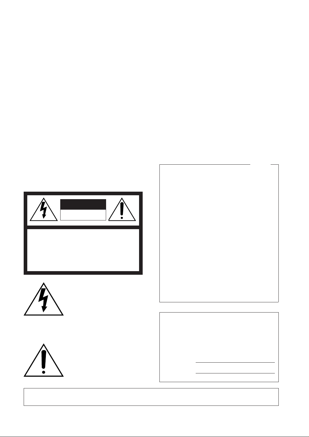
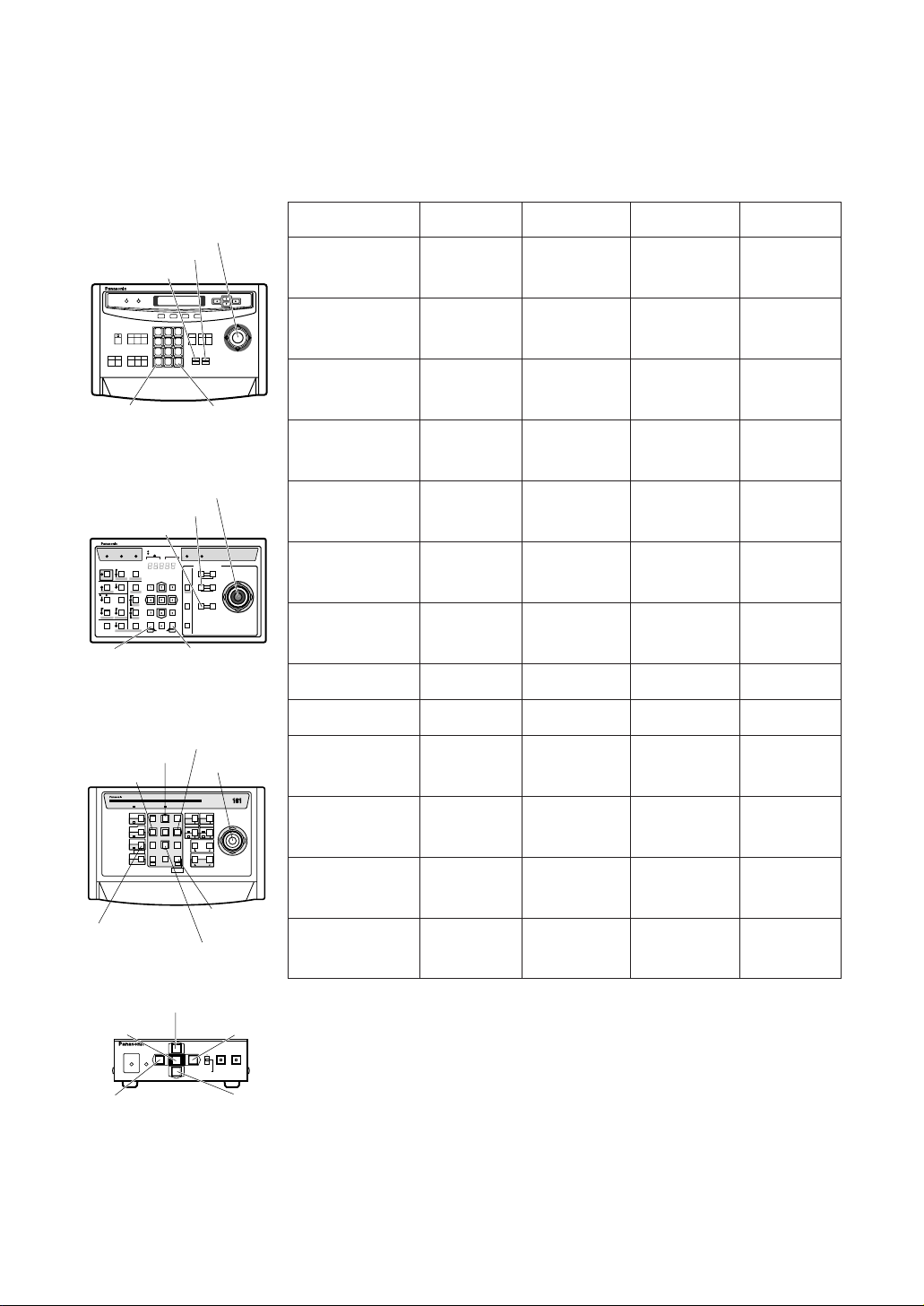
y Camera Mounting Base
u Panning Start Point
i Fall Prevention Wire
o Decoration Cover
!0 Dome Cover
q Alarm Input Connector
w Alarm Output Connector
e Video Output Connector
r Data Port
t Power Cable
CONSTRUCTION
q
w
yu
e
r
t
i
o
!0
Page 8
9
8
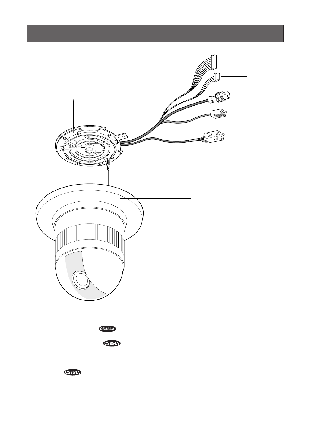
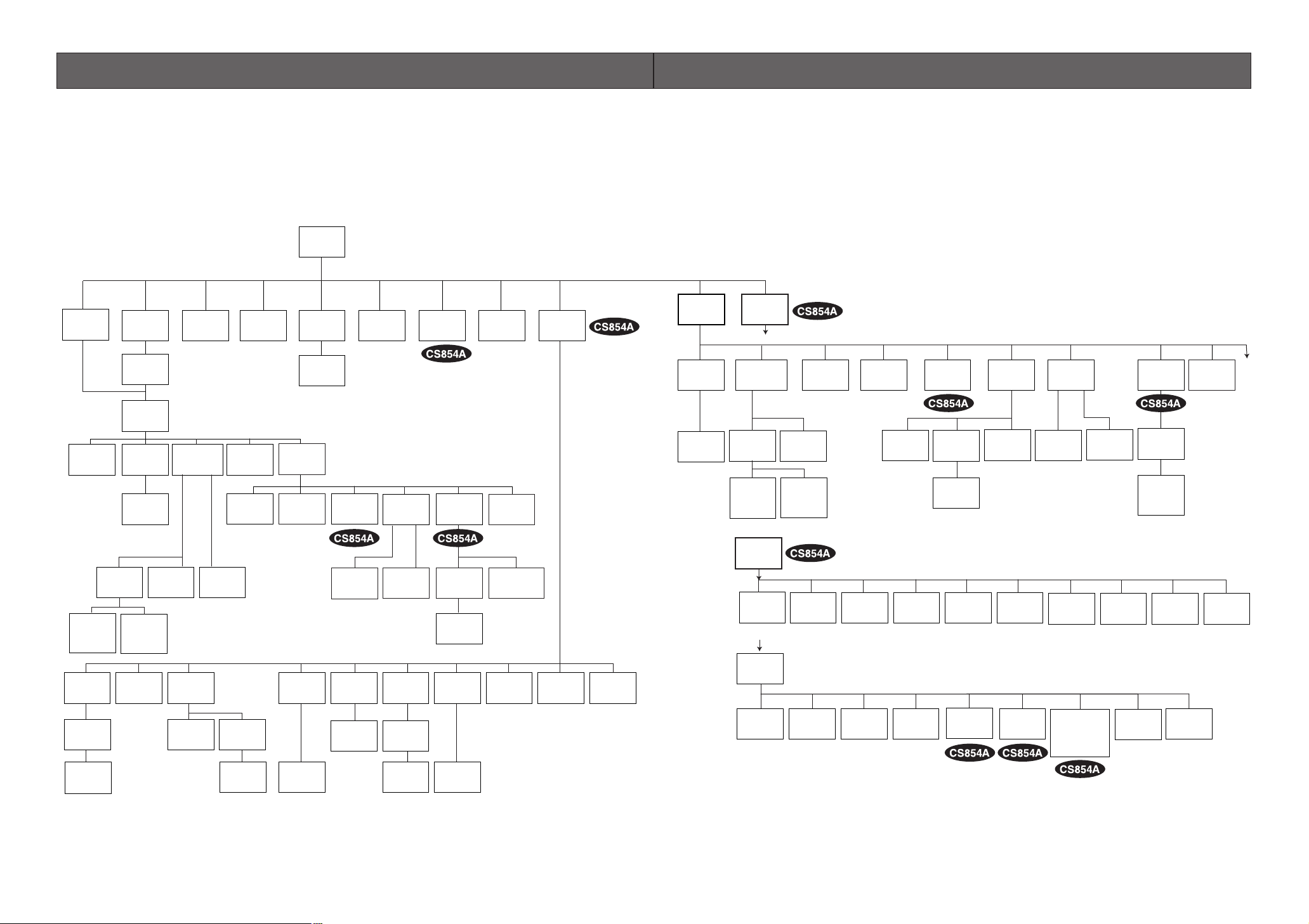
■ Setup Menu
Setup menus are shown in the diagram below. Various kinds of setup are available to have the camera
fulfill your requirements. Menus are built in a hierarchical structure from the Setup menu at the top down
to Manual Mask Area Selection at the bottom.
These menus are described in the following pages for reference prior to setup.
Switches, keys and the joystick are used for setup operations.
SETUP
Setup Menu
Home
Position
Selection
Self
Return
Setting
Auto Pan
Key
Setting
Digital
Flip
ON/OFF
Local/
Remote
Selection
PRESET
Menu
Auto Pan
Setting
Menu
Preset
Alarm
ON/OFF
Image Hold
ON/OFF
EL-Zoom
ON/OFF
Alarm
IN/OUT
Setting
Password
Registration
Password
Verification
Cleaning
Display
Cleaning
ON/OFF
Learning
Display
Patrol Learn
Play/Stop
Zone
Parameter
Setting
Zone
Number
Selection
Privacy Zone
ON/OFF
Propo.
P/T
ON/OFF
Password
Lock
ON/OFF
Direction
Setting
Area Title
Display
Area Title
Editing
Alarm
IN/OUT
Area Title
Selection
Auto
Mode
Selection
Special
1
Position
Setting
Light
Control
ALC/MANUAL
Dwell Time
Setting
MAP
Menu
Preset
No. SET
Menu
Preset
ID
Setting
Preset
ID
Editing
Scene File
Setting
Manual
Iris
Adjustment
Super-D2
ON
Super-D2
OFF
Manual
Mask
Area
Selection
Manual
Level
Adjustment
(Contrast)
Electronic
Sensitivity
Up ON/OFF
White
Balance
AWC ATW
Motion
Detector
ON/OFF
Shutter
Speed
ON/OFF
AGC
ON/OFF
AF Mode
Selection
Preset
Setting
Menu
Sensitivity
Level
Adjustment
Manual
Level
Adjustment
Manual
Level
Adjustment
Mask
Area
Selection
Demonstration
Display
Camera
Menu
CAMERA ID
Editing
CAMERA ID
Display
Position
RS-485
Setup
Light
Control
ALC/MANUAL
Super-D2
OFF
Manual
Level
Adjustment
(Contrast)
RS-485
Setup
A
Unit
Number
Selection
B
Special
2
Chroma
Gain
Adjustment
A
To
Super-D2
Manual
Selection
Adjustment
Selection
ON
Mask
Area
Sub-
Address
AP
Gain
Shutter
Speed
ON/OFF
BAUD
Rate
Selection
Pedestal
Adjustment
AGC
INT
Manual
Selection
Data
Selection
Hue
Adjustment
Bit
Sensitivity
Up
ON/OFF
LL
Manual
Selection
V-phase
Manual
Adjustment
Selection
Selection
Parity
Check
B/W
Sync
INT/LL
VD2
Automatic
Selection
Stop
Selection
Burst
ON/OFF
Selection
Bit
WHITE
BAL
AWC ATW
Manual
Level
Adjustment
Xon/Xoff
Selection
Digital Noise
Reduction
Mode Selection
LOW1/LOW2/
HIGH1/HIGH2
Manual
Level
Adjustment
Wait
Time
Selection
Refresh
Setting
Motion
Detector
ON/OFF
Manual
Level
Adjustment
Manual
Mask
Area
Selection
Alarm
Data
Selection
Camera
Reset
Setting
AF MODE
Selection
Delay Time
Selection
To
B
Page 9
10
Function/Controller
Open Special 2 F2 key
The keys (switches) to use for setup are as shown in the table below. The joystick on the connected controller may also be used for setup. The table also shows the functions versus the operations of the individual controllers. For further details, see the manual for the controller to be used. The switches and controls
are abbreviated as SW and CTRL in the table.
OPERATE LOGIN ALARM
FUNCTION
SX
IRIS
CLOSE OPEN
NEAR FAR
WIDE TELE
FOCUS
ZOOM
AUTO FOCUS
IRIS RESET
HOME
SET UP
ALM RECALL
CAM SETUP
CAM FUNCTION
MULTI SCREEN
DEF
WIPER
EL-ZOOM
SHIFT
ALM RESET
VTR CAM
STILL
-1 CAM/DEC
ALM SUSPEND
+1 CAM/INC
PATROLSTOP
AUX 1
AUX 2
B/W UNIT
SEQ PAUSE
BOOST
SEQUENCE AUTO
PRESET
POSI
FS
MON
CAM
LOGOUT
ESC SET
CAMERA SITE CONTROL
UP
LR
DOWN
BUSY PROHIBITED
MONITOR
UNIT
CAMERA
System Controller
WV-CU
360
1 2 3
4 5 6
7 8 9
MON CAM
ESC SET
0
ACK
RESET
BACK
SEQ
FORWARD
SEQ ALT
DEC
–1CAM
INC
+1CAM STOP
12
AUX
CLOSE OPEN
IRIS
PRESET
FOCUS
NEAR
ZOOM
TELE
FARWIDE
System Controller WV-CU550B
LEFT RIGHT
UP
DOWN
ALARM BUSY
F3 F4F2F1
AF
[WV-CU550B]
[WV-CU161]
[WV-RM70]
Joystick
CAM (SET)
Key
MON (ESC)
Key
CAM (SET)
Key
MON (ESC)
Key
SET Key
CAM (SET) Key
OPERATE
REMOTE
NORMAL PROG
ALARM
RESET
SYSTEM
ALARM OFF
Camera Controller WV-RM
7070
Up Switch
Set Switch
Right
Switch
Left Switch Down
Switch
[WV-CU360]
Joystick
Joystick
FOCUS Switch
ZOOM Switch
FOCUS Switch
ZOOM Switch
Up Switch
R
System Controller WV-CU
1 2 3
4 6
7 8 9
0
5
SHIFT
OPERATE ALARM
RESET
RESET
SUSPEND
CAMERA
SETUP
PATROL
PAY
PROGRAM
PRESET
CAMERA
FUNCTION
SERUP
ESC
HOME
SET
PRESET
WIDE TELE
NEAR
AUX1
B/W
AUTO
WIPER
AUX2
DEF
UP
DOWN
L
FAR
FOCUS
IRIS
CLOSS OPEN
PROGRAM
ALARM
IRIS RESET
AUTO FOCUS
Left Switch
Right Switch
Down Switch
WV-CU550B WV-CU360 WV-CU161 WV-RM70
Open CAM SETUP See page 16
CAM SETUP
key (for 2 seconds or more)
CAMERA SETUP
key (for 2 seconds or more)
See page 16
Close CAM SETUP F4 key
CAM SETUP
key (for 2 seconds or more)
CAMERA SETUP
key (for 2 seconds or more)
PROG SW
Move the cursor
Joystick
(←, ↑, ↓, →)
Joystick
(←, ↑, ↓, →)
Direction SW
(←, ↑, ↓, →)
Direction SW
(←, ↑, ↓, →)
Select a parameter
Joystick
(←, →)
Joystick
(←, →)
Direction SW
(←, →)
Direction SW
(←, →)
Adjust the level
Joystick
(←, →)
Joystick
(←, →)
Direction SW
(←, →)
Direction SW
(←, →)
Move the camera
direction
Joystick
(←, ↑, ↓, →)
Joystick
(←, ↑, ↓, →)
Joystick
(←, ↑, ↓, →)
Direction SW
(←, ↑, ↓, →)
Zoom & Focus
ZOOM CTRL &
FOCUS CTRL
ZOOM CTRL &
FOCUS CTRL
ZOOM CTRL &
FOCUS CTRL
Direction SW
(←, ↑, ↓, →)
Enter the setting CAM (SET) key CAM (SET) key CAM (SET) key SET SW
Open a submenu CAM (SET) key CAM (SET) key CAM (SET) key SET SW
Enter CAM ID &
PRESET ID
display position
MON (ESC) key MON (ESC) key SET key
SET SW
(for 2 seconds)
Enter MASK
setting
MON (ESC) key MON (ESC) key SET key
SET SW
(for 2 seconds)
All Reset F3 key
4+5+6 key
(for 2 seconds
or more)
4+5+6 key
(for 2 seconds
or more)
R+SET+L SW
(for 2 seconds)
4+6 key
(for 2 seconds
or more)
4+6 key
(for 2 seconds
or more)
R+L SW
(for 2 seconds)
Notes:
• A changed parameter is entered only when you move the cursor to
another item or open a new menu. A changed parameter will not be
entered if the setup menu is closed without taking either of the above
steps.
• Setting procedures in the following pages are described on the
assumption that the camera is used with WJ-SX550B Matrix Switcher
and WV-CU550B System Controller.
Page 10

11
■ Setup Menu Description
● PRESET
(1) Position (POSITION SET)
POSITION SET adjusts the camera picture by panning, tilting, zooming and focusing.
See page 17 for the setting.
(2) Preset Identification (PRESET ID)
A preset ID (identification of up to 16 alphanumeric characters) can be displayed on the screen.
See page 19 for the setting.
(3) Light Control (ALC/MANUAL)
ALC/MANUAL refers to the mode of the incoming light level control.
See page 20 for the setting.
(4) Dwell Time (DWELL TIME)
DWELL TIME is the duration that the picture of each camera position is displayed.
You can select a preset duration from the menu.
See page 21 for the setting.
(5) Scene File (SCENE FILE)
SCENE FILE stores up to 10 files. Each file has a set of detailed parameters for Shutter Speed, AGC,
Electronic Sensitivity Enhancement, White Balance, Motion Detector and AF mode. The scene files
can be recalled later to reproduce the parameter settings under the same conditions as stored in the
files.
See page 21 for the setting.
● Home Position (HOME POSITION)
HOME POSITION is the camera’s basic position. It returns to this position automatically, when a specific
time has elapsed after a manual operation. This setting functions only when AUTO MODE is OFF.
See page 22 for the setting.
● Self Return (SELF RETURN)
SELF RETURN is the time-out parameter for returning to the home position. The camera returns to AUTO
MODE if it is set to ON when a specific time has elapsed after a manual operation.
See page 22 for the setting.
● AUTO MODE
AUTO MODE is for setting the movement of the camera. You can select one from the four automatic operation modes and one manual operation mode as follows:
OFF mode: No automatic operation. The camera can be operated only manually.
SEQ mode: The camera operates in the sequence of preset positions in numerical order.
SORT mode: The camera operates in the sequence of preset positions counterclockwise from Pan/Tilt
Starting Point.
AUTO PAN mode: The camera automatically turns within the preset panning range.
PATROL mode: The camera operates in the patrol learn function.
See page 23 for the setting.
Page 11

12
● AUTO PAN KEY
This setting assigns SEQ, SORT, AUTO PAN or PATROL (PLAY) to the AUTO key on the controller. After
setting this, the AUTO key performs as assigned.
Note: AUTO PAN LED on the controller does not light if something other than AUTO PAN is assigned.
● DIGITAL FLIP ON/OFF
Tilt range is limited within 0° to 90° if OFF is selected. If ON is selected it widens the range up to 180° with
the digital flip that reverses horizontal and vertical scanning when the camera is tilted through the 90°
point (Downright position if the camera is installed on a ceiling). Tilt range narrows from 180° to 90° if PAN
LIMIT is set to ON.
● LOCAL/REMOTE
This setting determines whether the camera continues or stops the ongoing auto operation when the
System Controller is turned off.
LOCAL: The camera continues operating in auto mode when the controller is turned OFF.
REMOTE: The camera stops operating in auto mode approx.1 minute after the controller is turned off.
See page 25 for the setting.
● SPECIAL 1
(1) Privacy Zone ON/OFF (PRIVACY ZONE)
This setting is to mask unwanted zones, hiding them from display on the monitor. When (DIS) follows
ON or OFF, set PASSWORD LOCK to OFF if you want to change this setting. Up to 8 zones can be
registered. Submenus are provided for zone number selection and for parameter setting. See page
25 for details.
(2) Proportional Pan-Tilt Speed ON/OFF (PROPO. P/T)
If ON is selected, the zoom ratio changes corresponding to pan-tilt speed. For example, pan-tilt
speed slows down with zoom in. See page 27 for details.
(3) Area Title ON (NESW), ON (USER), OFF
Up to 8 area titles can be added to specific scenes by DIRECTION (NESW) or alphanumerical
(USER) naming. The titles are displayed right under the camera title on the monitor when the camera
turns to positions with area titles. See page 27 for details.
(4) Patrol Learn
A set of manual operations is stored (LEARN), reproduced (PLAY) or turned inactive (OFF). Patrol
operation stops if SEQ, SORT or AUTO PAN is set to AUTO MODE on the SETUP menu. See page 29
for details.
(5) Alarm IN/OUT (ALARM IN/OUT)
Alarm input and output are set on the submenu. Preset positions are assigned to ALARM IN 1 to 4. If
inputs are supplied via the ALARM INPUT connector, the camera turns to respective positions. Then,
the camera sends output signals via the ALARM OUT connector or the coaxial cable to the external
devices. B/W may be chosen instead of a preset position if light is so insufficient that color noise may
disturb picture clarity. CNT-CLS (Contact Closure) 1,2 and COAX ALM OUT are for alarm output setting. See page 31 for details.
(6) Password Lock ON/OFF (PASSWORD LOCK ON/OFF)
This setting controls access to the PRIVACY ZONE to be free or limited. If PASSWORD LOCK ON is
selected, the (DIS) follows the PRIVACY ZONE ON or OFF set on the SPECIAL 1 menu.
Page 12

13
(7) Cleaning ON/OFF
This is for refreshing the electric-mechanical contacts built in the camera. Use this function for maintenance when the camera has been directed to a specific spot or panned over a specific range for a
long time.
(8) Electric Zoom ON/OFF
Up to 10-fold ( 2-fold) electrical zooming is available beside 22-fold optical zooming.
(9) Preset Alarm ON/OFF
Alarm signals are output in the following cases if ON is selected.
• Positioning is completed in SEQ mode.
• Positioning is completed in SORT mode.
• Positioning is completed at HOME position in SELF RETURN mode.
• Positioning is completed in command request.
• Positioning is completed in ALARM IN.
• Positioning to the start point is completed for AUTO PAN.
• Positioning to the start point is completed for PATROL PLAY.
(10) Image Hold ON/OFF (IMAGE HOLD ON/OFF)
The camera picture remains as a still image on the monitor until the camera reaches the preset position. This function is useful for surveillance via local area network.
● Camera
(1) Camera Identification (CAMERA ID)
You can use the camera identification (CAMERA ID) to assign a name to the camera. The camera ID
consists of up to 16 alphanumeric characters. You can select whether to have the camera ID displayed on the monitor screen or not.
See page 35 for the setting.
(2) Light Control (ALC/MANUAL)
You can select the mode for adjusting the lens iris.
The modes are as follows:
ALC: The lens iris is automatically adjusted according to the brightness of the object. You can select
one of two modes (SUPER-D2 ON or SUPER-D2 OFF).
MANUAL: The lens iris is fixed at the value that you have set regardless of the brightness of the
object.
• ALC Mode with SUPER-D2 ON
Super-Dynamic 2 Function (SUPER-D2)
The important object in a scene is usually placed in the center of the monitor’s screen. In SUPER-D2
mode, more photometric weight is given to the center of the screen (where the important object is
located) than to the edge of the picture (where a bright backlight would most likely be located).
You can use the SUPER-D2 function if you select ALC.
It eliminates interference by strong background lighting which makes the camera picture dark, such
as a spotlight.
See page 36 for the setting.
• ALC Mode with SUPER-D2 OFF
In this mode, the picture is divided into 48 areas. If there is a source of brightness that interferes with
the clarity of the picture in these masks, corresponding areas mask the light to keep the clarity of the
picture.
Page 13

14
Generally, when a light from the background is too strong such as a spotlight, all objects except the
main object in the picture are displayed darker because the lens iris is adjusted with respect to
strong brightness. This model ignores strong brightness by masking the source of the strong brightness, thereby main object is displayed clearly.
Notes:
• The result of field setup of the mask area and level adjustment is fed back (effected) to the lens
iris control in ALC mode.
• Select OFF for SUPER-D2 on the ALC CONT menu when using only for outdoors.
If ON is selected for the SUPER-D2 parameter, a shadow (black line) may appear at the boundary between the bright and the dim scene. This is a natural phenomenon and does not indicate
trouble.
(3) Shutter Speed (SHUTTER)
You can select the shutter speed from 1/60 (OFF), 1/100, 1/250, 1/500, 1/1 000, 1/2 000, 1/4 000, and
1/10 000 seconds.
See page 38 for the setting.
(4) Gain Control (AGC)
You can set the gain (brightness level portion of an image) to automatic adjustment [Automatic Gain
Control ON (LOW, MID, HIGH)] or fixed (Automatic Gain Control OFF). The gain adjustment for WVCS554 is available only for On or Off.
See page 38 for the setting.
(5) Electronic Sensitivity Enhancement (SENS UP)
The electronic sensitivity enhancement (SENS UP) function varies the shutter speed to raise the sensitivity in low light conditions when OFF is selected for ALC.
You can select the shutter speed for SENS UP from the preset values as follows:
1/30 seconds (x2), 1/15 seconds (x4), 1/10 seconds (x6), 1/6 seconds (x10), 1/3.8 seconds (x16), or
1/1.9 seconds (x32). See page 38 for the setting.
There are two modes for SENS UP as follows:
AUTO: If you select x32, for example, the sensitivity is raised automatically to x32 max.
FIX: If you select x32, for example, the sensitivity is raised to just x32.
Notes:
• Moving objects will appear blurred when shot during the electronic sensitivity enhancement
mode since SENS UP is equivalent to setting the shutter speed to a slower speed in a still picture
camera.
• The horizontal and vertical resolution will be lowered in this mode.
• If the video output level is adjusted too low (the iris opening is too small), the Electronic
Sensitivity Enhancement (SENS UP)/AUTO mode will not function.
(6) Synchronization (SYNC)
You can select internal sync mode (INT) or line-lock sync (LL). Additionally, this model accepts the
VD2 signal (multiplexed vertical drive signal with the composite video output signal) from a specified
component. Whenever the VD2 signal is supplied to this camera, the camera automatically switches
to the VD2 sync mode.
When you select line-lock sync (LL) you can set vertical phase adjustment.
See page 39 for the setting.
Important Notices:
The priority of sync modes is as follows:
Page 14

15
1. Multiplexed Vertical Drive (VD2) (Highest)
2. Line-lock (LL)
3. Internal Sync (INT) (Lowest)
Note: The priority of automatic sync mode is the same as shown above.
(7) White Balance (WHITE BAL)
You can select one of two modes for white balance adjustment as follows:
• ATW (Auto Tracing White Balance)
In this mode, the color temperature is monitored continuously and thereby white balance is set automatically. The color temperature range for the proper white balance is approximately 2 600 - 6 000K.
Proper white balance may not be obtained under the following conditions:
1. The color temperature is out of the 2 600 - 6 000K range.
2. When the scene contains mostly high color temperature (bluish) objects, such as a blue sky.
3. When the scene is dim.
In these cases, select the AWC mode.
• AWC (Automatic White Balance)
In this mode, accurate white balance is obtained within a color temperature range of approx. 2 300 10 000K. See page 41 for the setting.
(8) Motion Detector (MOTION DET)
The Motion Detector detects the motion in the scene by monitoring changes in the brightness level.
You can select the level of sensitivity for motion on the SET UP menu.
When the camera detects the motion it supplies the alarm signal to the external equipment and stops
at its position for the preset DWELL time. See page 42 for the setting.
(9) Auto Focus (AF MODE)
The camera adjusts the focus automatically to the best position by sensing sharpness in the center
area of the picture. S, M and L stand for the breadth of the sensing area: Small, Middle and Large.
See page 43 for details.
MANUAL S, M, L: Auto-focus is activated when the AF key on the controller is pressed.
AUTO S, M, L: Auto-focus is activated automatically while operating manually (WV-CS854A): pan, tilt
or zoom. Auto-focus is activated automatically after a manual operation (WV-CS554).
Note: If SENS UP is set to ON except x2 FIX or x2 AUTO setting, AUTO (S/M/L) is disabled and
MANUAL (S/M/L) is automatically selected.
(10)Special 2 Menu (SPECIAL 2) or Special Menu (SPECIAL)
This menu allows you to adjust the following items: chroma level, aperture level, pedestal level, chroma phase (hue), and up side down. You can also reset your parameters to the values preset at the
factory. See page 44 for the setting.
● RS485 Communication
Communication parameters
• Full/Half duplex (page 51)
• Transmission speed (2 400 - 19 200 bps) (page 47)
• Parity bit, Stop bit, Flow control (page 47)
• Wait time, Delay time, Alarm output (page 47)
• Camera units (96 units max.) (page 49)
• Termination ON/OFF (page 51)
• Reset parameters (page 48)
Page 15
16
SETTING PROCEDURES
The following setting procedures are described on the assumption that this model is used in combination
with the WJ-SX550B Matrix Switcher and WV-CU550B System Controller. In case of using a controller
other than the WV-CU550B, refer to the table on page 10.
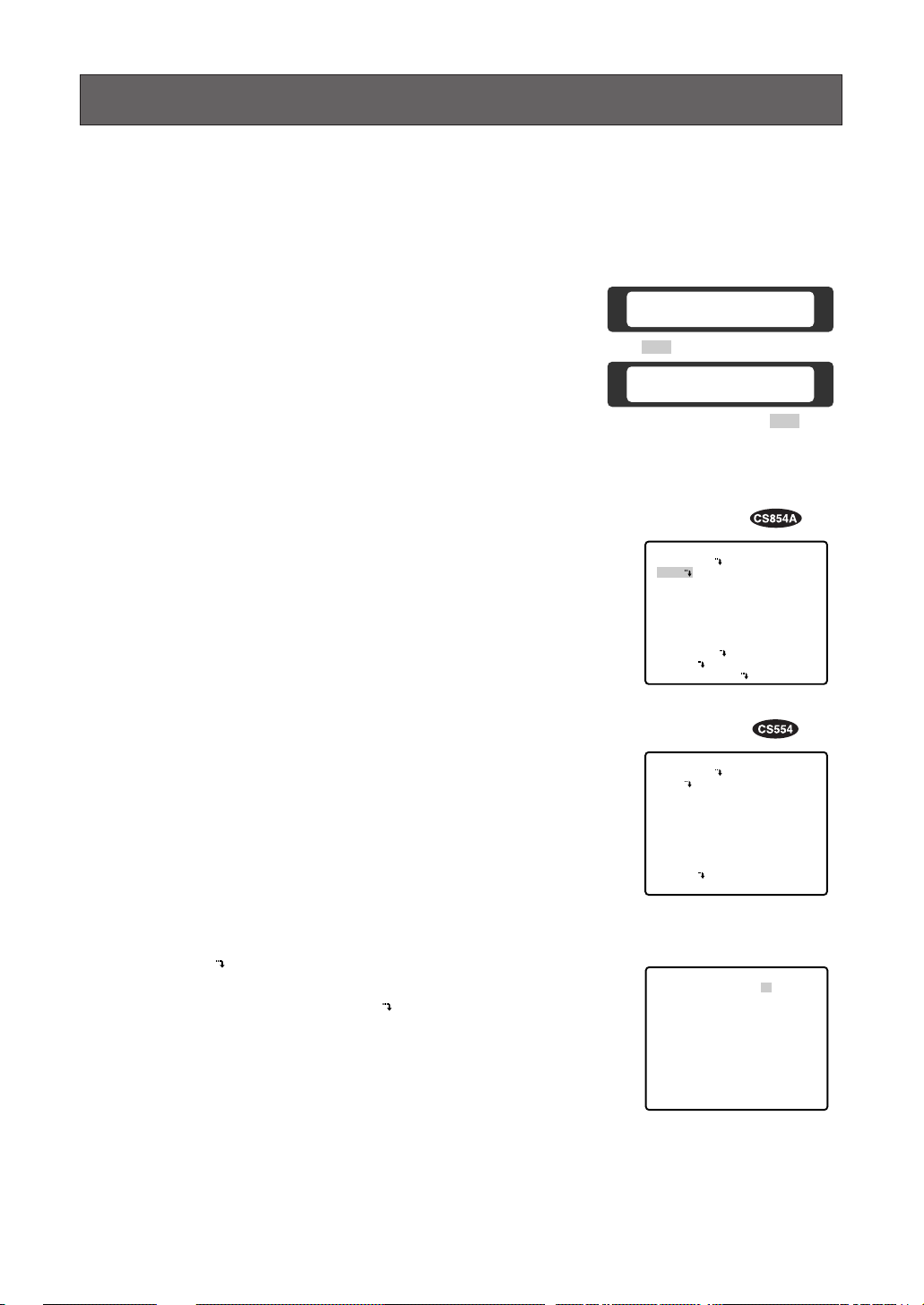
■ Menu Display
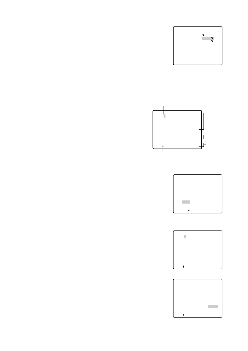
● Setup Menu Display
WV-CU550B
1. Select the number of the camera you want to set up and a monitor
to display the SET UP MENU.
2. Display the D4 menu on the LCD by pressing the appropriate cursor buttons.
3. Press the F1 button.
The SET UP MENU appears on the monitor.
4. To close the SET UP MENU, press the F4 button.
WV-CU360
Press the CAM SETUP key for 2 seconds or more to open the
SETUP menu.
WV-CU161
Press the CAMERA SETUP key for 2 seconds or more to open the
SETUP menu.
WV-RM70
1. Turn the MODE SELECTION switch to the NORMAL or ALARM
OFF position.
2. Press the PROG switch for 2 seconds or more to open the
Program menu.
3. Move the cursor to Camera Set Up, then press the SET switch to
open the SETUP menu.
D4 menu
Submenu
(for RS485 setup)
Setup menu
Setup menu
● Submenu Display
The items marked can be selected/changed on the submenu.
• Move the cursor to an item with the mark and press the CAM
(SET) key. The submenu is displayed.
Camera Set Up Menu
On Exit
F2 F3 F4
F1
Camera Set Up Menu
Res A.Res Exit
F1 F2 F3 F4
** SET UP MENU **
PRESET 1
MAP
HOME POSITION
SELF RETURN
AUTO MODE
AUTO PAN KEY
DIGITAL FLIP
LOCAL/REMOTE
SPECIAL1
CAMERA
RS485 SET UP
** SET UP MENU **
PRESET 1
MAP
HOME POSITION
SELF RETURN
AUTO MODE
AUTO PAN KEY
LOCAL/REMOTE
PATROL
CLEANING
CAMERA
OFF
OFF
OFF
AUTO PAN
ON
LOCAL
OFF
OFF
OFF
AUTO PAN
LOCAL
STOP
OFF
** RS485 SET UP **
UNIT NUMBER
SUB ADDRESS
BAUD RATE
DATA BIT
PARITY CHECK
STOP BIT
XON/XOFF
WAIT TIME
ALARM DATA
DELAY TIME
RET
1
1
19200
8
NONE
1
NOT USE
OFF
AUTO2
OFF
Page 16
17
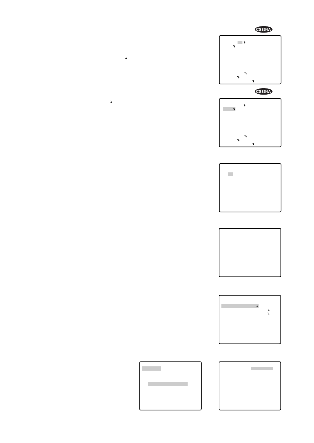
■ Preset
● Preset Menu Display
1. Displaying the preset menu directly
(1) Move the cursor to PRESET 1 and move the joystick to the
right or left to select the position number to be set.
(2) Press the CAM (SET) key.
The preset setting menu appears on the monitor screen.
2. Displaying the preset menu from the PRESET NUMBER SET menu
(1) Move the cursor to MAP and press the CAM (SET) key.
The PRESET NUMBER SET menu appears on the monitor
screen.
(2) Move the cursor to the position number to be set and press
the CAM (SET) key.
The preset setting menu appears on the monitor screen. To
display position number 33-64, move the cursor to “33-64” in
the lower left of the screen and press the CAM (SET) key.
Notes:
• The *mark means that the position number is preset.
• The character H means home position.
• On the second bottom line, the preset ID is displayed respective to the selected number. “DOOR” next to “ID” is for preset
position number 1 in the example shown right.
• Preset numbers 1 through 4 are linked to alarm inputs 1
through 4. If alarm input 1 comes in, the camera turns to preset position 1, or to other positions according to alarm input 2,
3 or 4.
• The PRESET NUMBER SET menu indicates the 8 preset positions (1 - 8) for the WV-CS554 combination camera.
PRESET NUMBER SET menu
(1-32)
PRESET NUMBER SET menu
(33-64)
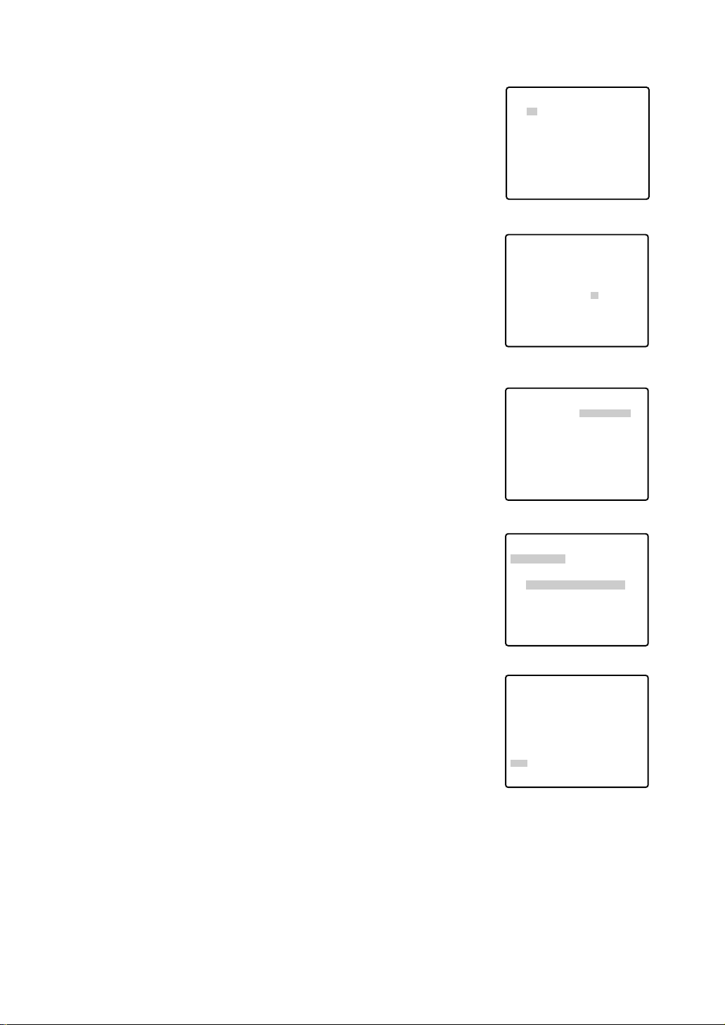
● Position Setting
1. Move the cursor to POSITION SET on the preset setting menu and
press the CAM (SET) key.
The position setting menu is displayed.
2. To Set Panning/Tilting Positions
(1) Move the cursor to PUSH SET next to PAN/TILT and press the
CAM (SET) key. The PAN/TILT setting menu appears.
(2) Select panning/tilting positions by moving the joystick up and
down, right and left, and press the CAM (SET) key.
The positions are set and the screen returns to the position setting
menu.
Preset setting menu
→
PUSH SET
→
PUSH SET
** POSITION 1 **
PAN/TILT
ZOOM/FOCUS
PAN OFFSET SET
← −
0.0
→
RET
FLOOR1
DOOR
Position setting menu
→
PUSH SET
→
PUSH SET
** POSITION 1 **
PAN/TILT
ZOOM/FOCUS
U TILT D/L PAN R
PAN OFFSET SET
← −
0.0
→
RET
FLOOR1
DOOR
Setup menu
PAN/TILT setting menu
Setup menu
** SET UP MENU **
PRESET 1
MAP
HOME POSITION
SELF RETURN
AUTO MODE
AUTO PAN KEY
DIGITAL FLIP
LOCAL/REMOTE
SPECIAL1
CAMERA
RS485 SET UP
OFF
OFF
OFF
AUTO PAN
ON
LOCAL
** SET UP MENU **
PRESET 1
MAP
HOME POSITION
SELF RETURN
AUTO MODE
AUTO PAN KEY
DIGITAL FLIP
LOCAL/REMOTE
SPECIAL1
CAMERA
RS485 SET UP
OFF
OFF
OFF
AUTO PAN
ON
LOCAL
** PRESET NUMBER SET **
2
1*
5
9
13
17
21
25
29
ID:DOOR
33-64 RET
6
10
14
18
22
26
30
3
7
11
15
19
23
27
31
4
8
12
16
20
24
28
32
** PRESET NUMBER SET **
34
33
37
41
45
49
53
57
61
ID:
1-32 RET
38
42
46
50
54
58
62
35
39
43
47
51
55
59
63
36
40
44
48
52
56
60
64
PRESET NO. 1*
POSITION SET
PRESET ID
ALC/MANUAL
DWELL TIME
SCENE FILE
PRESET SPEED
RET DEL
ON
ALC
10S
OFF
••••••••|
L H
Page 17
18
3. Pan Offset
If the camera is replaced with a new one, Pan Offset is used to
adjust its positions to be the same as before except patrol setting.
The controller can be downloaded or uploaded the camera preset
position data.
Caution: The preset data for conventional camera (WV-CS654 for
example) is incompatible with WV-CS854A’s. WV-CS854A’s
preset data will be destroyed if you upload the conventional
data. When this happened, prepare a WV-CS854A having the
initial factory settings. Download the factory settings into the
controller and then upload to the camera whose data is
destroyed.
(1) Display the PRESET NUMBER SET menu.
(2) Select a position number for the picture to be most enlarged
among the numbers by moving the joystick. Then press the
CAM (SET) key. POSITION setting menu appears.
(3) Move the cursor to PAN OFFSET SET and select the right or
left arrow by moving the joystick.
(4) Press the CAM (SET) key until the desired offset value in
degree appears.
(5) Move the cursor to other than PAN OFFSET, then press the
MON (ESC) key.
Notes:
• Further adjustment of the other positions is unnecessary. This
adjustment applies to all other positions.
• Make sure to move the cursor before pressing the key in step
5. Otherwise the settings will be ignored.
• Retry when the camera fails to upload or download the data.
4. To Set the Lens Zoom and Focus Positions
(1) Move the cursor to PUSH SET next to ZOOM/FOCUS and
press the CAM (SET) key. The ZOOM/FOCUS setting menu
appears.
(2) Select a zoom position by moving the zoom control up and
down, and a focus position by moving the focus control up
and down, and then press the CAM (SET) key.
The positions are set and the screen returns to the position
setting menu.
Notes:
• When the camera is used at a nearly horizontal angle, the
focus may not be adjustable to a high level of accuracy.
• If you move the cursor to POSITION number and move the
joystick right or left, the position number can be selected.
The selected preset position number can also be set after
pressing the CAM (SET) key.
• The preset and camera IDs appear at the lower-left corner of
the position setting menu after setting them.
5. Move the cursor to RET and press the CAM (SET) key to return to
the preset setting menu.
Position setting menu
Position setting menu
PRESET NUMBER SET menu
(1-32)
Position setting menu
ZOOM/FOCUS setting menu
** PRESET NUMBER SET **
2
1*
5
9
13
17
21
25
29
ID:DOOR
33-64 RET
6
10
14
18
22
26
30
3
7
11
15
19
23
27
31
4
8
12
16
20
24
28
32
** POSITION 1 **
PAN/TILT
ZOOM/FOCUS
PAN OFFSET SET
RET
FLOOR1
DOOR
→
PUSH SET
→
PUSH SET
← −
0.0
→
** POSITION 1 **
PAN/TILT
ZOOM/FOCUS
PAN OFFSET SET
RET
FLOOR1
DOOR
→
PUSH SET
→
PUSH SET
← −
0.0
→
** POSITION 1 **
PAN/TILT
ZOOM/FOCUS
U ZOOM D/L FOCUS R
PAN OFFSET SET
RET
FLOOR1
DOOR
→
PUSH SET
→
PUSH SET
← −
0.0
→
** POSITION 1 **
PAN/TILT
ZOOM/FOCUS
PAN OFFSET SET
RET
FLOOR1
DOOR
→
PUSH SET
→
PUSH SET
← −
0.0
→
Page 18
19
● Preset ID Setting
1. Move the cursor to PRESET ID on the preset setting menu and
select ON or OFF by moving the joystick to the right or left.
ON: Preset ID is displayed on the screen.
OFF: Preset ID is not displayed.
2. Press the CAM (SET ) key to display the preset ID setting menu.
To Enter a New PRESET ID
1. Move the cursor to the desired character using the joystick,
and press the CAM (SET) key.
2. The selected character appears in the editing area. (The
pointer in the editing area moves to the right automatically at
this moment.) To enter a blank, select SPACE.
3. Repeat the above procedure until all characters are
entered.
Preset ID setting menu
To Copy a Preset ID from Another Position
1. Move the cursor to COPY and press the CAM (SET) key. The
preset ID in the preceding position is immediately shown.
Each consecutive pressing of the CAM (SET) key displays the
ID preceding the one currently displayed.
2. Display the most prospective ID.
3. Follow the step “To change an entered PRESET ID” if necessary.
To Change an Entered PRESET ID
1. Move the pointer to the character to be edited in the editing
area by using the joystick, and press the CAM (SET) key.
2. Select a new character by using the joystick.
3. Press the CAM (SET) key to determine the PRESET ID.
To Delete an Entered PRESET ID
Move the cursor to RESET and press the CAM (SET) key.
Preset setting menu
PRESET NO. 1*
POSITION SET
PRESET ID
ALC/MANUAL
DWELL TIME
SCENE FILE
PRESET SPEED
RET DEL
Character Cursor
PRESET NO. 1*
0123456789
ABCDEFGHIJKLM
NOPQRSTUVWXYZ
().,'":;&#!?=
+-*/%$
SPACE
COPY POSI RET RESET
DOOR............
Pointer
ON
ALC
10S
OFF
••••••••|
L H
Character
Area
Command
Editing
Area
PRESET NO. 1*
0123456789
ABCDEFGHIJKLM
NOPQRSTUVWXYZ
().,'":;&#!?=
+-*/%$
SPACE
COPY POSI RET RESET
DOOR............
PRESET NO. 1*
0123456789
ABCDEFGHIJKLM
NOPQRSTUVWXYZ
().,'":;&#!?=
+-*/%$
SPACE
COPY POSI RET RESET
DOOR............
PRESET NO. 1*
0123456789
ABCDEFGHIJKLM
NOPQRSTUVWXYZ
().,'":;&#!?=
+-*/%$
SPACE
COPY POSI RET RESET
DOOR............
Page 19

20
To Set a Display Position for a PRESET ID
1. Move the cursor to POSI and press the CAM (SET) key. The
display position set menu appears.
2. Using the joystick, move the ID to the desired position on the
screen, then press the MON (ESC) key. The display position
is set and the screen returns to the PRESET ID setting menu.
Display position set menu
To Enter the Next ID without Returning to the Preset Setting
Menu
1. With the preset ID setting menu, move the cursor to the top
line and select the desired position number by moving the
joystick to the right or left.
2. Enter, copy, change or delete the ID as described above.
To Return to the Preset Setting Menu
Move the cursor to RET and press the CAM (SET) key.
● Light Control Setting
1. Move the cursor to ALC/MANUAL and select ALC or MANUAL by
moving the joystick to the right or left.
ALC: The lens iris is automatically adjusted to suit the brightness
of the object.
MANUAL: The lens iris is fixed at the set value regardless of the
brightness of the object.
2. In case of ALC
Press the CAM (SET) key. The backlight compensation menu
appears in the display. See page 36 for the setting.
3. In case of MANUAL
Press the CAM (SET) key. The setting menu appears in the display. Set the lens iris level as desired by moving the joystick to the
right or left.
Preset setting menu
Manual setting menu
PRESET NO. 1*
0123456789
ABCDEFGHIJKLM
NOPQRSTUVWXYZ
().,'":;&#!?=
+-*/%$
SPACE
COPY POSI RET RESET
DOOR............
FLOOR 1
DOOR
PRESET NO. 1*
0123456789
ABCDEFGHIJKLM
NOPQRSTUVWXYZ
().,'":;&#!?=
+-*/%$
SPACE
COPY POSI RET RESET
DOOR............
PRESET NO. 1*
POSITION SET
PRESET ID
ALC/MANUAL
DWELL TIME
SCENE FILE
PRESET SPEED
RET DEL
ON
ALC
10S
OFF
••••••••|
L H
** MANUAL CONT **
IRIS
••••|••••
CLOSE OPEN
RET
Page 20

21
Scene file setting menu
Scene file setting menu
Preset setting menu
** PRESET NUMBER SET **
2
6
10
14
18
22
26
30
1*
5
9
13
17
21
25
29
ID:DOOR
33-64 RET
3
7
11
15
19
23
27
31
4
8
12
16
20
24
28
32
PRESET NUMBER SET menu
Preset setting menu
● Dwell Time Setting
• Move the cursor to DWELL TIME and set a dwell time by moving
the joystick to the right or left. Dwell time changes as follows:
The letter S stands for second(s), and MIN stands for minute(s).
● Scene File Setting
1. To set a scene file number
Move the cursor to SCENE FILE and select a scene file number (1
to 10, or OFF) by moving the joystick to the right or left. No scene
file is selected at OFF.
2. To set scene file details
Move the cursor to a scene file number and press the CAM (SET)
key. The setting menu appears.
See the pages below for the setting.
Shutter speed: page 38
AGC: page 38
Electronic sensitivity enhancement: page 38
White balance: page 40
Motion detector: page 42
Auto focus: page 43
● Preset Speed
• Move the cursor to PRESET SPEED and select a speed by moving
the joystick to the right or left.
● To Return to the PRESET NUMBER SET Menu
• Move the cursor to RET and press the CAM (SET) key. The PRESET NUMBER SET menu appears with the *mark on the right of
the preset position number.
● To Return to the Setup Menu
• Move the cursor to RET and press the CAM (SET) key.
Preset setting menu
2S 3S 5S 10S 30S 1MIN 2MIN 3MIN 4MIN
PRESET NO. 1*
POSITION SET
PRESET ID
ALC/MANUAL
DWELL TIME
SCENE FILE
PRESET SPEED
RET DEL
ON
ALC
10S
OFF
••••••••|
L H
PRESET NO. 1*
POSITION SET
PRESET ID
ALC/MANUAL
DWELL TIME
SCENE FILE
PRESET SPEED
RET DEL
ON
ALC
10S
1
••••••••|
L H
** SCENE FILE 1 **
SHUTTER
AGC
SENS UP
WHITE BAL
MOTION DET
AF MODE
RET
OFF
ON(MID)
OFF
ATW
OFF
MANUAL M
** SCENE FILE 1 **
SHUTTER
AGC
WHITE BAL
AF MODE
OFF
ON
ATW
MANUAL M
RET
PRESET NO. 1*
POSITION SET
PRESET ID
ALC/MANUAL
DWELL TIME
SCENE FILE
PRESET SPEED
RET DEL
ON
ALC
10S
OFF
••••••••|
L H
Page 21

22
Preset setting menu
■ Deleting Preset Positions
1. Move the cursor to PRESET 1 and select the position number to
be deleted by moving the joystick.
2. Press the CAM (SET) key to display the preset setting menu.
3. Move the cursor to DEL and press the CAM (SET) key.
This deletes the preset position and the PRESET NUMBER SET
menu appears. The *mark on the right of the number disappears.
Note: Your selected preset number is canceled only in SEQ and
SORT mode. The previous set parameters (for PAN, TILT
positions, etc.) are not changed. If you want to change these
parameters, you must set them again.
Setup menu
■ Home Position Setting
1. To set a position number for the home position
Move the cursor to HOME POSITION and select the desired position number by moving the joystick to the right or left.
2. Select OFF if you are not using the home position function.
Note: This setting functions only when AUTO MODE is set to OFF.
PRESET NUMBER SET menu
Setup menu
■ Self Return Setting
• To set a time-out parameter for return to the home position
Move the cursor to SELF RETURN and select a return time by
moving the joystick to the right or left. Return time changes as follows:
Setup menu
MIN stands for minute(s).
Note: The camera will return to the AUTO MODE if that is set to
SEQ, SORT, AUTO PAN or PATROL when a specific time has
elapsed after a manual operation.
PRESET NUMBER SET menu
** SET UP MENU **
PRESET 1
MAP
HOME POSITION
SELF RETURN
AUTO MODE
AUTO PAN KEY
DIGITAL FLIP
LOCAL/REMOTE
SPECIAL1
CAMERA
RS485 SET UP
OFF
OFF
OFF
AUTO PAN
ON
LOCAL
PRESET NO. 1*
POSITION SET
PRESET ID
ALC/MANUAL
DWELL TIME
SCENE FILE
PRESET SPEED
RET DEL
ON
ALC
10S
OFF
••••••••|
L H
** PRESET NUMBER SET **
2
1*
5
9
13
17
21
25
29
ID:DOOR
33-64 RET
6
10
14
18
22
26
30
3
7
11
15
19
23
27
31
4
8
12
16
20
24
28
32
** PRESET NUMBER SET **
2
1*
5
ID:DOOR
RET
6
3
7
4
8
** SET UP MENU **
PRESET 1
MAP
HOME POSITION
SELF RETURN
AUTO MODE
AUTO PAN KEY
DIGITAL FLIP
LOCAL/REMOTE
SPECIAL1
CAMERA
RS485 SET UP
15
OFF
OFF
AUTO PAN
ON
LOCAL
1MIN
2MIN 3MIN 5MIN 10MIN
OFF
60MIN
30MIN 20MIN
** SET UP MENU **
PRESET 1
MAP
HOME POSITION
SELF RETURN
AUTO MODE
AUTO PAN KEY
DIGITAL FLIP
LOCAL/REMOTE
SPECIAL1
CAMERA
RS485 SET UP
OFF
10MIN
OFF
AUTO PAN
ON
LOCAL
Page 22

23
■ Auto Mode Selection
The menu screens follow the example for WV-CS854A.
1. To set auto mode
Move the cursor to AUTO MODE and select a mode by moving
the joystick to the right or left. Modes change as follows:
Setup menu
2. When AUTO PAN is selected, set details as follows:
Move the cursor to AUTO PAN and press the CAM (SET) key to
display the AUTO PAN setting menu.
3. To set a panning start position and panning end position
Follow the steps below.
(1) Move the cursor to POSITION SET and press the CAM (SET)
key.
The cursor moves to START.
(2) Move the joystick to the right or left to select a panning start
position and press the CAM (SET) key.
This determines the start position and the cursor moves to
END.
(3) Move the joystick to the right or left to select a panning end
position and press the CAM (SET) key.
This determines the end position and the cursor moves to
POSITION SET.
4. To set a panning speed
Move the cursor to SPEED, and move the joystick to the right or
left to set a panning speed.
The panning speed increases when the joystick is moved to the
right, and decreases when it is moved to the left.
Caution: If the panning range is changed after the camera has
not panned for a long time or has been panning in the same
panning range, the picture may not be clear or noise may
appear. In this case, pan the camera fully several times. If this
does not eliminate the problem, refer servicing to qualified
service personnel.
5. To set pan limit ON/OFF
Move the cursor to PAN LIMIT and select ON or OFF by moving
the joystick to the right or left.
ON: Manual pan is limited from the start point to the end point
specified by POSITION SET. Set endless turn to OFF before
pan limit is set to ON.
OFF: Manual pan is not limited.
Note: When ON is set, manual pan moves the camera away from
the other side of the start-end range.
AUTO PAN setting menu
OFF SEQ SORT AUTO PAN
PATROL
** SET UP MENU **
PRESET 1
MAP
HOME POSITION
SELF RETURN
AUTO MODE
AUTO PAN KEY
DIGITAL FLIP
LOCAL/REMOTE
SPECIAL1
CAMERA
RS485 SET UP
OFF
OFF
AUTO PAN
AUTO PAN
ON
LOCAL
OFF SEQ SORT AUTO PAN
** AUTO PAN **
POSITION SET
SPEED
PAN LIMIT
ENDLESS
DWELL TIME
RET
** AUTO PAN **
POSITION SET
SPEED
PAN LIMIT
ENDLESS
DWELL TIME
RET
** AUTO PAN **
POSITION SET
SPEED
PAN LIMIT
ENDLESS
DWELL TIME
RET
** AUTO PAN **
POSITION SET
SPEED
PAN LIMIT
ENDLESS
DWELL TIME
RET
START
END
••••|••••
L H
OFF
OFF
1S
START
END
••••|••••
L H
OFF
OFF
1S
START
END
••••|••••
L H
OFF
OFF
1S
START
END
••••|••••
L H
OFF
OFF
1S
Page 23

24
6. To set endless turn ON/OFF
Move the cursor to ENDLESS, and move the joystick to the right or
left to set endless turn ON or OFF.
ON: The camera pans from the start position to the end position,
then keeps rotating in the same direction to return to the start
position. Set pan limit to OFF before endless turn is set to ON.
OFF: The camera pans from the start position to the end position,
then rotates backward to the start position.
This movement is repeated over and over.
7. To set a dwell time
Move the cursor to DWELL TIME and select a dwell time by moving the joystick to the right or left. Dwell time changes as follows:
Notes:
• When the panning, tilting, zooming or focusing in SEQ, SORT
or PATROL (only for WV-CS854A) mode operation is controlled manually, the Auto mode function should be canceled.
To activate Auto mode, select the desired AUTO MODE again
or set a time for SELF RETURN in the SET UP menu to resume
the AUTO MODE after the time set.
• When 0S is selected, the camera stops without dwelling and
starts.
• Auto refreshing may be activated during PATROL PLAY or
AUTO MODE to calibrate the lens position.
■ AUTO PAN KEY Setting
This is to assign one of following auto function to the AUTO key on the
controller. Pressing the AUTO key activates the assigned function
after this setting. The menu screen follows the example for WVCS854A.
• Move the cursor to AUTO PAN KEY and select an auto function by
moving the joystick to the right or left.
Mode changes as follows:
AUTO PAN: assigns auto panning function to the key.
SEQ: assigns SEQUENCE function to the key.
SORT: assigns SORT function to the key
PATROL: assigns PATROL PLAY function to the key.
Note: AUTO PAN LED on the controller does not light if someting
other than AUTO PAN is assigned. AUTO PAN does not stop
with the AUTO PAN key.
Setup menu
** AUTO PAN **
POSITION SET
SPEED
PAN LIMIT
ENDLESS
DWELL TIME
RET
START
END
••••|••••
L H
OFF
ON
1S
0S
1S
2S 3S
30S 5S10S20S
SEQ SORT AUTO PAN
PATROL
** AUTO PAN **
POSITION SET
SPEED
PAN LIMIT
ENDLESS
DWELL TIME
RET
START
END
••••|••••
L H
OFF
OFF
1S
** SET UP MENU **
PRESET 1
MAP
HOME POSITION
SELF RETURN
AUTO MODE
AUTO PAN KEY
DIGITAL FLIP
LOCAL/REMOTE
SPECIAL1
CAMERA
RS485 SET UP
OFF
OFF
OFF
AUTO PAN
ON
LOCAL
Page 24

25
** SPECIAL 1 **
PRIVACY ZONE OFF(ENB)
PROPO.P/T ON
AREA TITLE ON(USER)
PATROL STOP
ALARM IN/OUT
PASSWORD LOCK OFF
CLEANING OFF
EL-ZOOM ON
PRESET ALM OFF
IMAGE HOLD OFF
RET
Special 1 menu
** ZONE NUMBER 1*/8 **
RET
ZONE NUMBER setting menu
Setup menu
■ DIGITAL FLIP ON/OFF
• Move the cursor to DIGITAL FLIP and select ON or OFF by moving the joystick to the right or left.
OFF: Tilt range is limited from 0° to 90°.
ON: The digital flip function allows the tilt angle to widen up to
180°. The image on the monitor screen is flipped horizontally
and vertically at the tilt angle of approx. 135°. (If the camera
is installed on a ceiling).
Note: Tilt range narrows from 180° to 90° if PAN LIMIT is set to
ON.
Notes:
• Digital flip functions while moving the joystick downwards. In case
of moving the joystick to other directions, it does not function.
• When OFF is selected for DIGITAL FLIP, the following operations
are required to move the camera 180° vertically.
1) Move the joystick downwards and the camera will aim below.
2) Move the joystick to the right or left and the camera will rotate
180° horizontally.
3) Move the joystick upwards.
• To set preset position directly from the WV-CU360 controller, it is
momentary required setting the electronic zoom function and digital flip function to OFF.
Tilt range setting is disabled between 90° and 180°.
■ LOCAL/REMOTE Setting
• Move the cursor to LOCAL/REMOTE, and move the joystick to the
right or left.
You can toggle between LOCAL and REMOTE.
Note: REMOTE does not work when the WV-RM70, WV-CU360,
WV-CU161, WJ-FS616, WJ-SX550B or WJ-SX850 is connected. Make sure that LOCAL is selected in this case.
■ SPECIAL 1
● Privacy Zone ON/OFF (PRIVACY ZONE)
Up to 8 unwanted zones can be masked on the monitor screen.
1. Move the cursor to PRIVACY ZONE and then select ON (ENB) or
OFF (ENB) by moving the joystick to the right or left. Press the
CAM (SET) key to display the ZONE NUMBER selection menu.
ON (ENB): Preset privacy zones are veiled on the monitor screen.
OFF (ENB): Veil function does not work.
Note: If (DIS) follows, instead of (ENB), after ON or OFF, step 2
onward are not applicable. Select OFF for PASSWORD LOCK
to take the following steps.
Setup menu
** SET UP MENU **
PRESET 1
MAP
HOME POSITION
SELF RETURN
AUTO MODE
AUTO PAN KEY
DIGITAL FLIP
LOCAL/REMOTE
SPECIAL1
CAMERA
RS485 SET UP
OFF
OFF
OFF
AUTO PAN
ON
LOCAL
** SET UP MENU **
PRESET 1
MAP
HOME POSITION
SELF RETURN
AUTO MODE
AUTO PAN KEY
DIGITAL FLIP
LOCAL/REMOTE
SPECIAL1
CAMERA
RS485 SET UP
OFF
OFF
OFF
AUTO PAN
ON
LOCAL
Page 25

26
** ZONE NUMBER 3*/8 **
PAN/TILT →PUSH SET
ZOOM/FOCUS →PUSH SET
U TILT D/L PAN R
ZONE SCALE ••••|••••
SET DEL L H
RET
PAN/TILT setting menu
** ZONE NUMBER 3*/8 **
PAN/TILT →PUSH SET
ZOOM/FOCUS →PUSH SET
ZONE SCALE ••••|••••
SET DEL L H
RET
ZONE setting menu
2. Select a zone number by moving the joystick to the right or left,
then press the CAM (SET) key.
• A zone number followed by * (asterisk) indicates that the zone has
already been registered.
• When a zone number having no * is selected, the picture is
zoomed out fully.
• When a registered zone number is selected, the camera moves to
the preset position. Note that if you move any of PAN/TILT,
ZOOM/FOCUS or ZONE SCALE in that position, the registered
zone number having no * is canceled.
• Zone frame appears in the center of the screen if 3 or fewer mask
areas exist in that picture and if the zone number is not registered
yet.
• The privacy zone setting may appear on the monitor depending
on the direction of the camera.
• Privacy zone function will not work at start-up immediately after
turning power on.
3. To register a new zone
3-1 Move the cursor to PUSH SET on the PAN/TILT line, then
press the CAM (SET) key.
3-2 Move the joystick to adjust the pan and tilt position so that the
desired position comes into the zone frame.
Note: Zone setting is not available while the zone frame disap-
pears, for example the camera directs further downward from
the 45° position.
3-3 Move the cursor to PUSH SET on the ZOOM/FOCUS, then
press the CAM (SET) key.
3-4 Adjust zoom and focus, then press the CAM (SET) key.
Zoom can be adjusted within the range of 1 to 10 magnifications.
3-5 Move the cursor to ZONE SCALE, and move the joystick to
the right or left to adjust the zone frame. Press the CAM (SET)
key after the adjustment.
Moving the joystick in the L direction decreases the zone
frame, and moving it in the H direction increases it. However,
the aspect ratio is fixed at 3 to 4.
The privacy zone setting has been completed.
The menu returns to the ZONE NUMBER setting menu. If DEL
is selected, zone setting is released and the ZONE NUMBER
setting menu appears.
** ZONE NUMBER 3*/8 **
PAN/TILT →PUSH SET
ZOOM/FOCUS →PUSH SET
ZONE SCALE ••••|••••
SET DEL L H
RET
ZONE SCALE setting menu
** ZONE NUMBER 3*/8 **
PAN/TILT →PUSH SET
ZOOM/FOCUS →PUSH SET
U ZOOM D/L FOCUS R
ZONE SCALE ••••|••••
SET DEL L H
RET
ZOOM/FOCUS setting menu
** ZONE NUMBER 1*/8 **
PAN/TILT →PUSH SET
ZOOM/FOCUS →PUSH SET
ZONE SCALE ••••|••••
SET DEL L H
RET
ZONE setting menu
Page 26

27
3-6
• To complete new settings and repeat another setting, move the cursor to SET and press the CAM
(SET) key. The ZONE NUMBER Selection menu returns.
• To cancel new settings and return to SPECIAL 1 MENU, move the cursor to DEL and press the
CAM (SET) key. New settings are not registered.
• To complete new settings and return to SPECIAL 1 MENU, move the cursor to RET and press the
CAM (SET) key.
● Proportional Pan/Tilt (PROPO. P/T)
• Move the cursor to PROPO. P/T and select either ON or OFF by
moving the joystick to the right or left.
Default : ON
ON: Pan/tilt speed is in inverse proportion to the zoom ratio as fol-
lows:
Zoom ratio Speed level
x1 8 (the fastest)
x2 5
x4 3
x8 1
x15 or more 0 (the slowest)
* The speed level values are approximate.
OFF: The speed is constant at the fastest level on the communi-
cation command regardless of the zoom ratio.
● Area Title (AREA TITLE)
Up to 8 area titles can be added in specific positions.
1. Select ON (NESW), ON (USER) or OFF by moving the joystick to
the right or left.
ON (NESW): An area title is displayed indicating the camera
direction: North (N), North-East (NE), East (E), South-East
(SE), South (S), South-West (SW), West (W) and North-West
(NW).
ON (USER): A user customized area title is displayed with a maxi-
mum of 16 characters.
OFF: Area tittle is not displayed.
Default : ON (USER)
2. Press the CAM (SET) key. A submenu appears except when OFF
is selected.
Settings for ON (NESW)
1. Move the cursor to PUSH SET on the PAN/TILT line, then press
the CAM (SET) key. PAN/TILT is highlighted and “U TILT D/L PAN
R” appears.
2. Move the joystick to turn the camera north, then press the CAM
(SET) key. The origin of the direction (North) is set.
Special 1 menu
** SPECIAL 1 **
PRIVACY ZONE OFF(ENB)
PROPO.P/T ON
AREA TITLE ON(NESW)
PATROL STOP
ALARM IN/OUT
PASSWORD LOCK OFF
CLEANING OFF
EL-ZOOM ON
PRESET ALM OFF
IMAGE HOLD OFF
RET
Special 1 menu
PUSH SET
PUSH SET
** DIRECTION(NESW) **
PAN/TILT
ZOOM/FOCUS
POSI
+
N
RET
p
p
AREA TITLE (NESW) setting menu
PUSH SET
PUSH SET
** DIRECTION(NESW) **
PAN/TILT
ZOOM/FOCUS
POSI
U TILT D/L PAN R
+
N
RET
p
p
PAN/TILT setting menu
** SPECIAL 1 **
PRIVACY ZONE OFF(ENB)
PROPO.P/T ON
AREA TITLE ON(USER)
PATROL STOP
ALARM IN/OUT
PASSWORD LOCK OFF
CLEANING OFF
EL-ZOOM ON
PRESET ALM OFF
IMAGE HOLD OFF
RET
Page 27

28
Note: Area titles appear in reverse video until the origin is set.
3. Move the cursor to PUSH SET on the ZOOM/FOCUS line, then
press the CAM (SET) key. ZOOM/FOCUS is highlighted and “U
ZOOM D/L FOCUS R” appears.
4. Move the joystick to adjust the zoom or focus.
5. Move the cursor to POSI , then press the CAM (SET) key. The
display position of the area title appears on the monitor. If needed, change the display position by moving the joystick, then press
the MON (ESC) key.
An area title is always displayed under the camera ID.
If the camera ID and an area title are set to be shown in separate
positions, the area title display position has priority over the camera ID setting.
6. Move the cursor to RET, then press the CAM (SET) key. SPECIAL
1 menu appears again.
Setting [ON (USER)]
If ON (USER) is selected on the SPECIAL 1 menu, the Area Title
selection menu appears. The screen has the number column and
title column above RET and RESET.
Note: The area numbers followed by an asterisk * have already
preset.
1. To select a camera direction, move the cursor to the desired number, then press the CAM (SET) key. The direction menu of the
selected number appears.
2. Adjust PAN/TILT, ZOOM/FOCUS and display position in the as
same way as AREA TITLE, DIRECTION (NESW). See page 27.
3. To add a user-customized title, move the cursor to the title of the
desired number, then press the CAM (SET) key. AREA TITLE
menu of the selected number appears.
AREA TITLE Editing
1. Move the cursor to the desired character in the character field
using the joystick then press the CAM (SET) key.
2. The selected character appears in the editing field and the blinking cursor moves one position to the right.
3. Repeat steps 1 and 2 until one area title is completed.
4. Move the cursor to POSI , then press the CAM (SET) key. The
display position of the area title appears on the monitor. If needed, change the display position by moving the joystick, then press
the MON (ESC) key.
PUSH SET
PUSH SET
** DIRECTION(NESW) **
PAN/TILT
ZOOM/FOCUS
POSI
U ZOOM D/L FOCUS R
+
N
RET
p
p
ZOOM/FOCUS setting menu
FLOOR 1
N
Display Position setting menu
PUSH SET
PUSH SET
** DIRECTION(USER) 1 **
PAN/TILT
ZOOM/FOCUS
+
NORTH
RET DEL
p
p
DIRECTION (USER) setting menu
** AREA TITLE(USER) **
1* NORTH
2
3 EAST
4 SOUTH-EAST
5 SOUTH
6 SOUTH-WEST
7
8 NORTH-WEST
RET RESET
AREA TITLE (USER) selection menu
** SPECIAL 1 **
PRIVACY ZONE OFF(ENB)
PROPO.P/T ON
AREA TITLE ON(USER)
PATROL STOP
ALARM IN/OUT
PASSWORD LOCK OFF
CLEANING OFF
EL-ZOOM ON
PRESET ALM OFF
IMAGE HOLD OFF
RET
SPECIAL 1 menu
Page 28

29
To Quit Editing
• To return to the Area Title menu, move the cursor to RET, then
press the CAM (SET) key.
• To cancel one area title, move the cursor to RESET, in the AREA
TITLE menu, then press the CAM (SET) key.
• To return to the SPECIAL 1 menu, move the cursor to RET, then
press the CAM (SET) key.
• To erase all the area titles, move the cursor to RESET, in the AREA
TITLE selection menu, then press the CAM (SET) key.
Notes:
• An area title is displayed under the camera ID if both of them
are set in the same position. If different, they are displayed in
the area title position.
• An area title appears while the camera direction deviates
within 45 degrees from the set position. If two or more area
numbers share a common subject in a scene, the title of the
largest number is displayed.
● Patrol (PATROL)
A routine of manual operations can be stored for 30 seconds at maximum and reproduced repetitively.
PATROL
1. For PATROL LEARN, set the following parameters for the starting
position. These parameters are stored when PATROL LEARN
mode starts.
• PAN/TILT/ZOOM/FOCUS settings
• IRIS setting
• SHUTTER setting
• AGC setting
• SENS UP setting
• WHITE BALANCE setting
• IMAGE HOLD setting
• AREA TITLE setting
• DIGITAL FLIP setting
• PRIVACY ZONE setting
• CAMERA ID setting
• PROPO.PT setting
• PAN LIMIT setting
• BURSTsetting
• CLEANING setting
After starting LEARN, the following manual operations are stored.
• PAN/TILT/ZOOM/FOCUS operation
• IRIS operation
• Preset position movement
2. Open the SET UP menu and move the cursor to SPECIAL 1.
Select LEARN, PLAY or STOP for PATROL by moving the joystick to the right or left.
LEARN: A series of manual operations is stored.
PLAY: Stored operations are reproduced.
STOP: LEARN or PLAY is not activated.
Display Position setting menu
** SPECIAL 1 **
PRIVACY ZONE
PROPO.P/T
AREA TITLE
PATROL
ALARM IN/OUT
PASSWORD LOCK
CLEANING
EL-ZOOM
PRESET ALM
IMAGE HOLD OFF
RET
OFF(ENB)
ON
ON(USER)
PLAY
OFF
OFF
ON
OFF
SPECIAL 1 menu
Setup menu
AREA TITLE 1*
0123456789
ABCDEFGHIJKLM
NOPQRSTUVWXYZ
().,'":;&#!?=
+-*/%$
SPACE
POSI RET RESET
................
AREA TITLE menu
FLOOR 1
NORTH
** SET UP MENU **
PRESET 1
MAP
HOME POSITION
SELF RETURN
AUTO MODE
AUTO PAN KEY
LOCAL/REMOTE
PATROL
CLEANING
CAMERA
OFF
OFF
OFF
AUTO PAN
LOCAL
STOP
OFF
Page 29

30
PATROL LEARN with a Controller Having PATROL Key
1. Press the PATROL key and the CAM (SET) key simultaneously to
start PATROL LEARN. The setup menu changes to show “LEARNING” and the starting point parameters are stored.
2. Operate manually. Operations data is stored.
3. To stop, press the PATROL STOP key.
PATROL LEARN with a Controller not Having PATROL Key
1. Close the SET UP or SPECIAL 1 menu to start PATROL LEARN.
Starting point parameters are stored and “LEARNING” is displayed on the monitor.
2. Operate manually.
3. Open the SET UP menu to stop learning.
Notes:
• It is recommended that you set PAN LIMIT to ON for PATROL LEARN. Otherwise PAN LIMIT is
invalid for playback.
• Restart from the beginning if the power has failed during PATROL LEARN.
• LEARN also stops 30 seconds after starting, or if the memory is full.
• Auto refreshing may be activated during PATROL PLAY or AUTO MODE to calibrate the lens
position.
PATROL PLAY with a Controller Having PATROL Key
1. Press the PATROL key. The camera turns to the starting point and the operations stored in the memory are reproduced. Iris operation only is accepted during playback.
2. Press the PATROL STOP key to stop playback or press any manual operation key (e.g.,
PAN/TILT/ZOOM/FOCUS) except the iris keys.
PATROL PLAY with a Controller not Having PATROL Key
1. Close the SET UP or SPECIAL 1 menu. The camera turns to the starting point and the operations
stored in the memory are reproduced. Iris operation only is accepted during playback.
2. Open the SET UP menu, or press any manual operation key (e.g., PAN/TILT/ ZOOM/FOCUS) except
the iris keys to stop playback.
PATROL PLAY with AUTO PAN Key
1. If the PATROL PLAY function is assigned to the AUTO PAN key, press the AUTO PAN key to turn the
camera back to the starting point and to reproduce the operation data stored in the memory.
2. Press the PATROL STOP key or any manual operation key (e.g., PAN/TILT/ZOOM/FOCUS) except the
iris keys to stop playback.
Notes:
• During PATROL PLAY, the camera movement may occasionally deviate from the entered routine
when the routine includes a move to a preset position. If this happens, re-enter the routine of manual
operations in PATROL LEARN.
• During PATROL PLAY, black and white automatic switching does not work.
• During PATROL PLAY, when the power of the system controller is turned on or off, PATROL PLAY
stops. In case of this, press the PATROL PLAY key again. (If SELF RETURN is set, PATROL PLAY will
start again after elapsing the setting return time.)
PATROL LEARN
LEARNING
Page 30

31
● Alarm IN/OUT (ALARM IN/OUT)
Move the cursor to ALARM IN/OUT, then press the CAM (SET) key.
ALARM I/O submenu appears.
Note: While the camera is in AF mode or the lens moves between
WIDE and TELE, alarm input may be ignored if several alarm
inputs are received in succession.
ALARM IN 1-4
Alarm input signals are supplied from external devices through
the ALARM IN connector to turn the camera to a preset position.
1. Move the cursor to ALARM IN 1* and select a preset position or
OFF by moving the joystick, then press the CAM (SET) key.
* Set ALARM IN 2, 3 and 4 in the same way as ALARM IN 1.
1 POSI, 2 POSI, 3 POSI, 4 POSI: Preset position. If an alarm input is received, the camera turns to a
preset position, then sends alarm output signal. Position number correspond to alarm input numbers (1-1, 2-2, 3-3 and 4-4).
B/W: Available for ALARM INPUT 4 only. The camera changes its mode from color to black and white
if ALARM IN 4 is supplied.
OFF: The camera ignores alarm inputs.
Note: If two or more alarm inputs are received while the camera is moving to a preset position, the
camera starts to aim at preset positions in small preset numerical order after current positioning.
CNT-CLS 1-2 (Output)
Two contact closure signals (Open collector type) are output through the ALARM OUT connector.
1. Move the cursor to CNT-CLS 1, then select OFF, ALARM or AUX 1 by moving the joystick to the right
or left.
When ALARM is selected, TIME OUT appears. Select an appropriate duration from among 100 MS,
200 MS, 1000 MS (1 s), 2000 MS (2 s), 4000 MS (4 s) by moving the joystick to the right or left.
Note: The shorter the duration, the more frequent will be the detection output.
2. Move the cursor to CNT-CLS 2, then select OFF, B/W or AUX 2 by moving the joystick to the right or
left.
OFF: Contact closure signals are inactivated.
ALM: Available for CNT-CLS 1 only. Motion detection is output.
AUX 1(2): An alarm signal is output when the camera receives a command from the controller.
B/W: Available for CNT-CLS 2 only. ON (active) is output when the camera operates in black and
white mode if ALARM IN 4 is set to B/W.
Note: We recommend that you set the connected external device to ignore the shorter alarm outputs
of 90 ms or less from the camera.
COAXIAL ALARM OUT
Alarm output signals are supplied through the coaxial cable.
1. Move the cursor to COAX and select ON or OFF.
ALARM I/O submenu
** SPECIAL 1 **
PRIVACY ZONE
PROPO.P/T
AREA TITLE
PATROL
ALARM IN/OUT
PASSWORD LOCK
CLEANING
EL-ZOOM
PRESET ALM
IMAGE HOLD OFF
RET
OFF(ENB)
ON
ON(USER)
STOP
OFF
OFF
ON
OFF
SPECIAL 1 menu
** ALARM IN/OUT **
ALARM IN 1
ALARM IN 2
ALARM IN 3
ALARM IN 4
CNT-CLS 1
TIME OUT
CNT-CLS 2
COAX ALM OUT
RET
OFF
OFF
OFF
OFF
OFF
100MS
OFF
OFF
Page 31

32
2. Press the CAM (SET) key.
ON: The camera sends an alarm output signal via the coaxial cable after it turns to a preset position.
OFF: The camera does not send the output signal.
Notes:
• The camera ignores alarm inputs during manual operation.
• Select OFF when the camera downloads or uploads the preset data.
● Password Lock (PASSWORD LOCK)
Caution: For security, do not operate your VCR for recording while the
password menus are displayed on the monitor.
A 3-digit number is used for a password to limit access to the privacy
zone settings.
1. Move the cursor to PASSWORD LOCK, then select ON or OFF by
moving the joystick to the right or left.
Note: ON or OFF can be changed only after going through the
password verification.
OFF: Access to the privacy zone settings is free. (ENB) follows
after ON or OFF of PRIVACY ZONE on the SPECIAL 1 menu.
ON: Access is limited by the verification menu. (DIS) follows ON
or OFF of PRIVACY ZONE on the SPECIAL 1 menu.
2. Press the CAM (SET) key.
PASSWORD VERIFICATION
3. The password verification menu appears.
3-1 Select a numeral for the first digit by moving the joystick to the right or left, then press the CAM
(SET) key. Though the entered password is not displayed, the up-arrow moves one character to
the right.
3-2 Repeat the above step for the 2nd and 3rd digits.
Default : 123.
3-3 The cursor moves to OK after all the three digits have been entered. Except for changing the
password to a new one, press the CAM (SET) key.
If the correct password is entered, the screen returns to SPECIAL 1. The ON or OFF set on the
SPECIAL 1 menu is as set in step 1.
If a wrong password is entered, the screen returns to the verification menu. Repeat steps 3-1 to
3-3 to verify the password.
3-4 To cancel a password incomplete or of a wrong number, move the cursor to RESET or OK, and
press the CAM (SET) key. The screen returns to the verification menu.
3-5 To return to the SPECIAL 1 menu without verifying the password, move the cursor to RET, then
press the CAM (SET) key.
NEW PASSWORD
4. To change the password in step 3-3 above, move the cursor from
OK to NEW PASSWORD, then press the CAM (SET) key. NEW
PASSWORD menu appears.
Notes:
• NEW PASSWORD menu is accessible only after the verification has been completed.
PASSWORD
** SPECIAL 1 **
PRIVACY ZONE OFF(ENB)
PROPO.P/T ON
AREA TITLE ON(USER)
PATROL STOP
ALARM IN/OUT
PASSWORD LOCK ON
CLEANING OFF
EL-ZOOM ON
PRESET ALM OFF
IMAGE HOLD OFF
RET
Special 1 menu
NEW PASSWORD
** PASSWORD? **
0 1 2 3 4 5 6 7 8 9
. . .
OK RESET
NEW PASSWORD
RET
** NEW PASSWORD? **
0 1 2 3 4 5 6 7 8 9
. . .
. . .
OK RESET
RET
↑
↑
Page 32

33
• The following operations for NEW PASSWORD will not affect to ON/OFF changing of the PRIVACY ZONE on the SPECIAL 1 menu.
The up-arrow mark appears indicating the first digit on the first line.
4-1 Enter a new three-digit password in the same way as in steps 3-1 to 3-2.
4-2 The cursor moves to OK after all the three digits is entered. Press the CAM (SET) key to move the
cursor to the first digit on the second line.
4-3 Enter the same password as you have entered on the first line.
4-4 The cursor moves to OK. Press the CAM (SET) key. If the new password is successfully entered,
the screen returns to SPECIAL 1.
4-5 Retry step 4-1 to 4-4. If the first entry for the password is different from the second one, the
screen returns to the NEW PASSWORD? menu.
4-6 To return to the SPECIAL 1 menu without changing the password, move the cursor to RET, then
press the CAM (SET) key.
● Cleaning ON/OFF (CLEANING ON/OFF)
CLEANING
Built-in electric mechanical contacts are refreshed at regular intervals
(approx. 7 days) if CLEANING is set to ON.
A dry contract affects adversely picture quality and motors operation.
1. Move the cursor to CLEANING and select ON or OFF by moving
the joystick to the right or left.
ON: The contacts are cleaned as programmed for about 1
minute. “CLEANING” disappears when it is over.
OFF: No contact cleaning.
Note: Select OFF when the camera downloads or uploads the
preset data.
● Electric Zoom ON/OFF (EL-ZOOM ON/OFF)
The electric zoom magnifies a scene 10-fold. With a 22-fold optical
zoom lens, the camera is capable of 220-fold zoom (44-fold zoom for
WV-CS554).
1. Move the cursor to EL-ZOOM and select ON or OFF by moving
the joystick to the right or left, then press the CAM (SET) key.
ON: Tenfold electric zoom is available with the ZOOM switch on
the controller.
OFF: The electric zoom function is not used.
Special 1 menu
** SET UP MENU **
PRESET 1
MAP
HOME POSITION
SELF RETURN
AUTO MODE
AUTO PAN KEY
LOCAL/REMOTE
PATROL
CLEANING
CAMERA
OFF
OFF
OFF
AUTO PAN
LOCAL
STOP
ON
Setup menu
CLEANING
CLEANING
** SPECIAL 1 **
PRIVACY ZONE OFF(ENB)
PROPO.P/T ON
AREA TITLE ON(USER)
PATROL STOP
ALARM IN/OUT
PASSWORD LOCK OFF
CLEANING OFF
EL-ZOOM ON
PRESET ALM OFF
IMAGE HOLD OFF
RET
Special 1 menu
** SPECIAL 1 **
PRIVACY ZONE OFF(ENB)
PROPO.P/T ON
AREA TITLE ON(USER)
PATROL STOP
ALARM IN/OUT
PASSWORD LOCK OFF
CLEANING ON
EL-ZOOM ON
PRESET ALM OFF
IMAGE HOLD OFF
RET
Page 33

34
Notes:
• A scene magnified by EL-ZOOM may be inferior to a nonmagnified one in picture quality.
• The electronic zoom does not function in preset position setting mode.
• To set preset position directly from the WV-CU360 controller,
it is momentary required setting the electronic zoom function
to OFF.
● Preset Alarm ON/OFF (PRESET ALARM ON/OFF)
An alarm output is sent when the camera moves to the designated
position respective to the mode.
1. Move the cursor to PRESET ALARM and select ON or OFF.
ON: Alarm signals are sent out in the following cases.
• Positioning is completed in AUTO SEQ mode.
• Positioning is completed in AUTO SORT mode.
• Positioning to the HOME position is completed in SELF
RETURN mode.
• Positioning is completed for a position request command.
• Positioning to the designated point is completed for ALARM
IN/OUT.
• Positioning to the start point is completed for AUTO PAN.
• Positioning to the start point is completed for PATROL PLAY.
OFF: Alarm signals are not output.
Note: Select OFF when the camera downloads or uploads the
preset data.
● Image Hold ON/OFF (IMAGE HOLD ON/OFF)
The camera picture remains as a still image on the monitor until the
camera reaches the preset position. This function is useful for surveillance via local area network.
1. Move the cursor to IMAGE HOLD and select ON or OFF.
ON: The last displayed still image is shown till the camera finishes
moving to a preset position. However, the still image may be
distorted with the effect of panning or tilting.
OFF: The current image is displayed while the camera is moving
to a preset position.
** SPECIAL 1 **
PRIVACY ZONE OFF(ENB)
PROPO.P/T ON
AREA TITLE ON(USER)
PATROL STOP
ALARM IN/OUT
PASSWORD LOCK OFF
CLEANING OFF
EL-ZOOM ON
PRESET ALM ON
IMAGE HOLD OFF
RET
Special 1 menu
Camera setting menu
** SPECIAL 1 **
PRIVACY ZONE OFF(ENB)
PROPO.P/T ON
AREA TITLE ON(USER)
PATROL STOP
ALARM IN/OUT
PASSWORD LOCK OFF
CLEANING OFF
EL-ZOOM ON
PRESET ALM OFF
IMAGE HOLD ON
RET
Special 1 menu
** SET UP **
CAMERA ID
ALC/MANUAL
SHUTTER
AGC
SYNC
WHITE BAL
AF MODE
EL-ZOOM
RET SPECIAL
OFF
ALC
OFF
ON
INT
ATW
MANUAL M
ON
Page 34

35
■ Camera Setting
1. To Display the Camera Setting Menu
• Move the cursor to CAMERA , and press the CAM (SET) key.
The camera setting menu is displayed.
Setup menu
** SET UP **
CAMERA ID
ALC/MANUAL
SHUTTER
AGC
SYNC
WHITE BAL
AF MODE
EL-ZOOM
RET SPECIAL
OFF
ALC
OFF
ON
INT
ATW
MANUAL M
ON
Camera setting menu
Character editing menu
CAM1
** SET UP **
CAMERA ID
ALC/MANUAL
SHUTTER
AGC
SENS UP
SYNC
WHITE BAL
MOTION DET
AF MODE
RET SPECIAL2
OFF
ALC
OFF
ON(MID)
X2 AUTO
INT
ATW
OFF
MANUAL M
2. Camera Identification Setting (CAMERA ID)
1. Move the cursor to CAMERA ID, and select ON (to display the
camera identification) or OFF by using the joystick.
2. Follow the steps below to edit the camera ID characters:
2-1 Move the cursor to CAMERA ID and press the CAM (SET) key
to display the character editing menu.
2-2 Move the cursor to the character you want to edit or change
by using the joystick, and press the CAM (SET) key. The
selected character appears in the editing area.
2-3 Repeat the steps above until all characters are edited.
3. After editing the camera identification characters, follow the steps
below to set the position of the CAMERA ID on the monitor
screen.
3-1 Move the cursor to POSI, and press the CAM (SET) key to
display the ID position menu.
3-2 Use the joystick to decide the position of the CAMERA ID on
the monitor screen. Press the MON (ESC) key to fix the position, and return to the character editing menu.
Notes:
• When you want the pointer to move to a specific character in
the editing area, select a new character, and press the CAM
(SET) key. This function allows you to edit or correct a specific character.
• When you want a blank space in the CAMERA ID, move the
character cursor to SPACE, and press the CAM (SET) key.
• When you want to erase all characters in the editing area,
move the cursor to RESET and press the CAM (SET) key.
Setup menu
Camera setting menu
** SET UP MENU **
PRESET 1
MAP
HOME POSITION
SELF RETURN
AUTO MODE
AUTO PAN KEY
DIGITAL FLIP
LOCAL/REMOTE
SPECIAL1
CAMERA
RS485 SET UP
OFF
OFF
OFF
AUTO PAN
ON
LOCAL
** SET UP MENU **
PRESET 1
MAP
HOME POSITION
SELF RETURN
AUTO MODE
AUTO PAN KEY
LOCAL/REMOTE
PATROL
CLEANING
CAMERA
OFF
OFF
OFF
AUTO PAN
LOCAL
STOP
OFF
CAMERA ID
0123456789
ABCDEFGHIJKLM
NOPQRSTUVWXYZ
().,'":;&#!?=
+-*/%$
SPACE
POSI RET RESET
CAM1............
Page 35

36
• The positioning of the CAMERA ID stops at the edges of the
screen.
• The CAMERA ID moves faster when the joystick is kept to the
right or left for one second or more.
• To return to SET UP for setting other items, move the cursor to
RET, and press the CAM (SET) key.
3. Light Control Setting (ALC/MANUAL)
1. Display SET UP on the monitor screen.
If necessary, refer to Setup Menu Display on page 16 for details
on displaying the SET UP on the monitor screen.
2. Move the cursor to ALC/MANUAL and select ALC or MANUAL by
using the joystick. When you select ALC, set backlight compensation.
Note: The backlight compensation submenu associated with this
menu is described separately and should be set up after
installing the camera at the site and observing the actual site
picture.
3. When MANUAL is selected, quit the setup menu by pressing
MON (ESC) key. Press OPEN or CLOSE key on the controller for
iris adjustments.
Camera setting menu
Backlight compensation menu
(1) ALC Mode with SUPER-D2 ON
1. Press the CAM (SET) key after selecting ALC. The ALC CONT
menu appears.
2. Move the cursor to the SUPER-D2 parameter and select ON.
3. If you want to adjust the video output level, move the cursor to the
“I” position. Adjust to the desired level by using the joystick.
4. Move the cursor to RET and press the CAM (SET) key to return to
the CAM SET UP menu. (To return to the camera picture, press
the F4 button.)
CAMERA ID
0123456789
ABCDEFGHIJKLM
NOPQRSTUVWXYZ
().,'":;&#!?=
+-*/%$
SPACE
POSI RET RESET
CAM1............
CAMERA ID
0123456789
ABCDEFGHIJKLM
NOPQRSTUVWXYZ
().,'":;&#!?=
+-*/%$
SPACE
POSI RET RESET
CAM1............
** SET UP **
CAMERA ID
ALC/MANUAL
SHUTTER
AGC
SENS UP
SYNC
WHITE BAL
MOTION DET
AF MODE
RET SPECIAL2
OFF
ALC
OFF
ON(MID)
X2 AUTO
INT
ATW
OFF
MANUAL M
** ALC CONT **
BACK LIGHT COMP
SUPER-D2
MASK SET
LEVEL
RET
** ALC CONT **
BACK LIGHT COMP
SUPER-D2
LEVEL
OFF
••••|••••
- +
ON
••••|••••
- +
RET
Page 36

37
Blinking
Blinking
Blinking
Turns to white
(2) ALC Mode with SUPER-D2 OFF
1. Move the cursor to the SUPER-D2 parameter and select OFF.
(When you select MANUAL, SUPER-D2 is not available.) The item
MASK SET appears on the menu.
2. Move the cursor to MASK SET and press the CAM (SET) key. The
48 mask areas appear on the monitor screen. The cursor is blinking in the top left corner of the screen.
3. To mask an area where backlight is bright, move the cursor to that
area then press the CAM (SET) key. The mask turns white. Repeat
this procedure to mask the desired area.
4. To cancel a masked area, move the cursor to that area, then
press the CAM (SET) key. To cancel all masking area, press the
F2 button of the WV-CU550B. (For the WV-RM70, press the right
and left switches simultaneously.)
5. After masking is completed, press the MON (ESC) key. The 48
mask areas on the monitor screen disappear and the field setup
menu appears.
6. If you want to change the video output level (picture contrast),
move the “I” cursor for LEVEL and adjust the level.
7. Move the cursor to RET and press the CAM (SET) key to return to
the CAM SET UP menu. (To return to the camera picture, press
the F4 button.)
** ALC CONT **
BACK LIGHT COMP
SUPER-D2
MASK SET
LEVEL
RET
** ALC CONT **
BACK LIGHT COMP
SUPER-D2
MASK SET
LEVEL
RET
OFF
••••|••••
- +
OFF
••••|••••
- +
Page 37

38
Camera setting menu
4. Shutter Speed Setting (SHUTTER)
Note: When ON is selected for SUPER-D2 on the ALC CONT menu,
this item is not available.
To select electronic shutter speed, select OFF for SUPER-D2 in
the menu.
1. Display SET UP on the monitor screen.
If necessary, refer to Setup Menu Display on page 16 for details
on displaying the SET UP menu on the monitor screen.
2. Move the cursor to SHUTTER and select the electronic shutter
speed by using the joystick.
The electronic shutter speed changes as follows by operating the
joystick:
• When OFF is selected for SUPER-D2 on the ALC CONT menu
5. Gain Control Setting [AGC ON (LOW/MID/HIGH)/OFF]
1. Display SET UP on the monitor screen.
If necessary, refer to Setup Menu Display on page 16 for details
on displaying the SET UP menu on the monitor screen.
2. Move the cursor to AGC and select automatic level adjustment
ON (LOW), ON (MID), ON (HIGH) or fixed level (OFF) by using the
joystick.
ON (LOW): Selects lower gain control.
ON (MID): Selects normal gain control.
ON (HIGH): Selects higher gain control.
OFF (Fixed Level): Disables the gain control function.
Notes:
• Even if AGC is set to ON and if the noise reduction function is
enabled, afterimages may be produced by shooting a moving
object or by panning or tilting the camera.
• For more information, refer to digital noise reduction mode
selection (see page 45).
• Select ON or OFF at the WV-CS554 gain control setting.
6. Electronic Sensitivity Enhancement Setting
(SENS UP)
1. Display SET UP on the monitor screen.
If necessary, refer to Setup Menu Display on page 16 for details
on displaying the SET UP menu on the monitor screen.
2. Move the cursor to SENS UP and select the desired electronic
sensitivity enhancement mode by using the joystick.
The electronic sensitivity enhancement mode changes as follows
by operating the joystick:
Camera setting menu
Camera setting menu
Camera setting menu
Camera setting menu
OFF (1/60) 1/100
1/250 1/500
1/10 000 1/4 000 1/2 000 1/1 000
** SET UP **
CAMERA ID
ALC/MANUAL
SHUTTER
AGC
SENS UP
SYNC
WHITE BAL
MOTION DET
AF MODE
RET SPECIAL2
OFF
ALC
OFF
ON(MID)
X2 AUTO
INT
ATW
OFF
MANUAL M
** SET UP **
CAMERA ID
ALC/MANUAL
SHUTTER
AGC
SYNC
WHITE BAL
AF MODE
EL-ZOOM
RET SPECIAL
OFF
ALC
OFF
ON
INT
ATW
MANUAL M
ON
** SET UP **
CAMERA ID
ALC/MANUAL
SHUTTER
AGC
SENS UP
SYNC
WHITE BAL
MOTION DET
AF MODE
RET SPECIAL2
OFF
ALC
OFF
ON(MID)
X2 AUTO
INT
ATW
OFF
MANUAL M
** SET UP **
CAMERA ID
ALC/MANUAL
SHUTTER
AGC
SYNC
WHITE BAL
AF MODE
EL-ZOOM
RET SPECIAL
OFF
ALC
OFF
ON
INT
ATW
MANUAL M
ON
** SET UP **
CAMERA ID
ALC/MANUAL
SHUTTER
AGC
SENS UP
SYNC
WHITE BAL
MOTION DET
AF MODE
RET SPECIAL2
OFF
ALC
OFF
ON(MID)
X2 AUTO
INT
ATW
OFF
MANUAL M
Page 38

39
• When ON is selected for SUPER-D2 on the ALC CONT menu
• When OFF is selected for SUPER-D2 on the ALC CONT menu
Notes:
• When ON is selected for SUPER-D2 in the ALC CONT menu, FIX
is not available for this item.
• When you select AUTO for SENS UP and ON for SUPER-D2, the
SENS UP function has priority so that the SUPER-D2 function is
not activated automatically.
• While the SENS UP function is selected, noise or spots may
appear in the picture when the sensitivity of the camera is
increased. This is a normal phenomenon.
7. Synchronization Setting (SYNC)
1. Display SET UP on the monitor screen.
If necessary, refer to Setup Menu Display on page 16 for details
on displaying the SET UP menu on the monitor screen.
2. Move the cursor to SYNC and select line-lock (LL) or internal (INT)
by using the joystick. The menu screen follows the example for
WV-CS854A.
Important Notices:
1. The priority of SYNC modes is as follows:
1. Multiplexed vertical drive (VD2) (highest priority)
2. Line-lock (LL)
3. Internal sync (INT) (lowest priority)
2. To use internal sync, select INT.
3. Whenever the vertical drive pulse (VD2) is supplied to the camera, the camera sync mode is automatically switched to the multiplexed vertical drive (VD2) regardless which sync mode is selected.
Line-lock Sync Mode (LL)
1. Display SET UP on the monitor screen.
(Refer to Setup Menu Display on page 16 for details on displaying
the SET UP menu on the monitor screen.)
2. Move the cursor to SYNC and select LL by using the joystick. LL
sync mode is not available when the multiplexed vertical drive
(VD2) pulse is supplied.
Camera setting menu
** SET UP **
CAMERA ID
ALC/MANUAL
SHUTTER
AGC
SENS UP
SYNC
WHITE BAL
MOTION DET
AF MODE
RET SPECIAL2
OFF
ALC
OFF
ON(MID)
X2 AUTO
LL
ATW
OFF
MANUAL M
Camera setting menu
OFF
X2 AUTO
X16 AUTO
X4 AUTO X6 AUTO X10 AUTO
X32 AUTO X2 FIX
X4 FIXOFF
X6 FIX X10 FIX X16 FIX X32 FIX
OFF
X2 AUTO
X4 AUTO X6 AUTO X10 AUTO X16 AUTO X32 AUTO
** SET UP **
CAMERA ID
ALC/MANUAL
SHUTTER
AGC
SENS UP
SYNC
WHITE BAL
MOTION DET
AF MODE
RET SPECIAL2
OFF
ALC
OFF
ON(MID)
X2 AUTO
INT
ATW
OFF
MANUAL M
Page 39

40
3. After selecting LL, press the CAM (SET) key.
The SYNC menu appears on the monitor screen.
4. Supply the video output signal of the camera to be adjusted and
the reference camera video output signal (for example, Camera 1)
to a dual-trace oscilloscope.
5. Set the dual-trace oscilloscope to the vertical rate and expand the
vertical sync portion on the oscilloscope.
6. Move the cursor to COARSE by using the joystick.
7. Use the joystick to match the vertical phases for both video output
signals as closely as possible. (COARSE adjustment can be
incremented in steps of 22.5 degrees (16 steps) with the joystick.)
SYNC menu
1 (1 - - - 16): 0 degrees
2 (1 - - - 16): 22.5 degrees
16 (1 - - - 16): 337.5 degrees
Note: After the 16 steps, the adjustment returns to the first step.
8. Move the cursor to FINE by using the joystick.
9. Use the joystick to match the vertical phase for both video output
signals as closely as possible.
Notes:
• When the “|” cursor reaches the “+” end, it jumps back to “–”.
At the same time, COARSE is incremented by one step to
enable a continuous adjustment. The reverse takes place
when the “|” cursor reaches the “–” end.
• When the joystick is kept to the right or left for one second or
more, the “|” cursor moves quickly.
• To reset COARSE and FINE to the preset values at the factory,
press the F2 button of the WV-CU550B. (For the WV-RM70,
press the Right and Left switches simultaneously.) COARSE is
preset at the factory to zero-crossing of the AC line phase.
• If the AC line contains noise (spike noise, etc.), the stability of
the vertical phase of the camera video output signal may be
disturbed.
8. White Balance Setting (WHITE BAL)
(1) Auto-Tracing White Balance Mode (ATW)
The menu screens follow the example for WV-CS854A.
1. Display SET UP on the monitor screen.
(Refer to Setup Menu Display on page 16 for details on displaying
the SET UP menu on the monitor screen.)
Camera setting menu
** SYNC **
V PHASE
COARSE
FINE
1(1--16)
•|•••••••
- +
RET
** SYNC **
V PHASE
COARSE
FINE
RET
** SYNC **
V PHASE
COARSE
FINE
RET
** SYNC **
V PHASE
COARSE
FINE
RET
1(1--16)
•|•••••••
- +
4(1--16)
••••••|••
- +
1(1--16)
•|•••••••
- +
** SET UP **
CAMERA ID
ALC/MANUAL
SHUTTER
AGC
SENS UP
SYNC
WHITE BAL
MOTION DET
AF MODE
RET SPECIAL2
OFF
ALC
OFF
ON(MID)
X2 AUTO
INT
ATW
OFF
MANUAL M
Page 40

41
2. Move the cursor to WHITE BAL and select ATW by using the joystick. The white balance of the camera is automatically set.
3. For fine adjustment of the ATW, press the CAM (SET) key to display the ATW fine adjustment menu on the monitor screen.
4. Move the cursor to “R.”
Use the joystick to obtain the optimum amount of red gain. The “I”
cursor moves to the right or left.
5. Move the cursor to “B.”
Use the joystick to obtain the optimum amount of blue gain. The
“I” cursor moves to the right or left.
6. Move the cursor to RET by using the joystick and press the CAM
(SET) key to return to SET UP.
(2) Automatic White Balance Control Mode (AWC)
1. Display SET UP on the monitor screen.
(Refer to Setup Menu Display on page 16 for details on displaying
the SET UP menu on the monitor screen.)
2. Move the cursor to WHITE BAL and select AWC → PUSH SW by
using the joystick.
3. Press the CAM (SET) key to start the white balance setup. PUSH
SW is highlighted to indicate that white balance is being set.
4. “PUSH SW” returns to normal when balance setting is completed.
5. For fine adjustment of the AWC, move the cursor
to select AWC and press the CAM (SET) key to
display the AWC fine adjustment menu on the
monitor screen.
6. Move the cursor to “R.”
Use the joystick to obtain the optimum amount
of red gain. The “I” cursor moves to the right or
left.
7. Move the cursor to “B.”
Use the joystick to obtain the optimum amount
of blue gain. The “I” cursor moves to the right or
left.
8. Move the cursor to RET by using the joystick
and press the CAM (SET) key to return to SET
UP.
ATW fine adjustment menu
AWC fine adjustment menu
Camera setting menu
Blue sky
Cloudy
Fine
AWC
10000 K
Bluish
Reddish
9000 K
8000 K
7000 K
6000 K
5000 K
4000 K
3000 K
2000 K
1000 K
ATW
Halogen lamp
Rainy
Partly cloudy
Fluorescent
lamp
Tungsten
lamp
Candle
** ATW **
R
B
RET
••••|••••
- +
••••|••••
- +
** SET UP **
CAMERA ID
ALC/MANUAL
SHUTTER
AGC
SENS UP
SYNC
WHITE BAL
MOTION DET
AF MODE
RET SPECIAL2
OFF
ALC
OFF
ON(MID)
X2 AUTO
INT
AWC
→PUSH SW
OFF
MANUAL M
** AWC **
R
B
••••|••••
- +
••••|••••
- +
RET
Page 41

42
9. Motion Detector Setting (MOTION DET)
1. Display SET UP on the monitor screen.
(Refer to Setup Menu Display on page 16 for details on displaying the SET UP menu on the monitor screen.)
2. Move the cursor to MOTION DET and select ON or OFF by using
the joystick. Then press the CAM (SET) key when you select ON.
3. When you select ON, the motion detect setup menu appears.
You can mask the areas in this menu.
4. Move the cursor to MASK SET and press the CAM (SET) key.
48 mask areas appear on the monitor screen.
Refer to the Light Control Setting section on page 36 for masking
operations.
5. After masking areas, press the MON (ESC) key. The motion
detect setup menu appear on the monitor screen.
6. Move the cursor to ALARM and select ON or OFF by using the
joystick.
ON: The alarm signal is supplied while the DISPLAY MODE is
activated.
OFF: The alarm signal is not supplied while the DISPLAY MODE
is activated.
7. Move the cursor to DISPLAY MODE.
Press the CAM (SET) key to see the present setting. The areas
that detect the motions start blinking.
8. Move the cursor to LEVEL by using the joystick.
Use the joystick to obtain the optimum detection level. The “I”
cursor moves to the right or left.
Note: Repeat the above procedures until you obtain the desired
adjustment.
9. Move the cursor to RECOVER TIME by using the joystick.
You can select the following recover times.
Camera setting menu
Motion detect menu
10. Move the cursor to RET and press the CAM (SET) key to return to
SET UP.
** SET UP **
CAMERA ID
ALC/MANUAL
SHUTTER
AGC
SENS UP
SYNC
WHITE BAL
MOTION DET
AF MODE
RET SPECIAL2
OFF
ALC
OFF
ON(MID)
X2 AUTO
INT
ATW
ON
MANUAL M
** MOTION DETECT **
LEVEL
DISPLAY MODE
ALARM
MASK SET
RECOVER TIME
RET
••••|••••
- +
OFF
1MIN
OFF
1MIN 2MIN 3MIN 5MIN
60MIN
30MIN 20MIN 10MIN
Page 42

43
Important Notices:
• The object of motion detection should meet the following conditions.
1) It should be larger than 1/48 of the size of the picture screen.
2) The contrast ratio (at max. detection level) between the object and the background picture on the
screen should be more than 5 %.
3) The time it takes the object to move from one end of the screen to the other should be more than
0.1 seconds.
• Also under the following conditions, mask or adjust the detection level to prevent malfunction.
1) When leaves or curtains etc, are swayed by the wind.
2) When a noisy picture exists such as under low light condition.
3) When the object is subjected to illumination by lighting equipment that constantly turns on and
off.
• The alarm signal will take about 0.2 second to reach the alarm terminal of the VCR, after the camera
detects the object.
Because the alarm signal is multiplexed on the video signal it may be mistakenly interpreted by other
video equipment as a time code signal. Therefore, when this camera is not used in a Panasonic
Intelligent CCTV System, select OFF to prevent the above from occurring.
10.Auto Focus Setting (AF MODE)
The menu screen follows the example for WV-CS854A.
1. Move the cursor to AF MODE, then select the following mode by
moving the joystick to the right or left. S, M and L stand for Small,
Middle and Large areas in the center of a scene that are used for
sensing sharpness in auto-focusing.
Camera setting menu
AUTO S AUTO M AUTO L
MANUAL L MANUAL M MANUAL S
MANUAL S, M, L: Brings the camera into focus when the AF key on the controller is pressed.
AUTO S, M, L: Brings the camera into focus while operating pan, tilt or zoom manually (WV-
CS854A). Bring the camera into focus after manual pan, tilt or zoom (WV-CS554). These may be
selected in the same way as selecting MANUAL by pressing the AF key on the controller.
2. To confirm auto-focus operation, press CAM (SET) key while the cursor is at AF MODE.
Notes:
• When the electronic sensitivity enhancement (SENS UP) is activated except x2 FIX or x2 AUTO setting, this function is automatically set to MANUAL (S, M, L).
• The auto focus lens does not function properly in AUTO after using WIDE lens.
• The auto focus lens may not function properly in AUTO under the following conditions.
1. Dirt or water on window glass.
The auto focus may focus on the dirt or water.
2. Low lighting/illumination or zone marker is blinking.
3. Bright objects or high intensity objects.
4. Single color with unfigured object such as white wall or fine felt.
5. No center objects, sloping objects.
6. Far and near objects on the screen.
** SET UP **
CAMERA ID
ALC/MANUAL
SHUTTER
AGC
SENS UP
SYNC
WHITE BAL
MOTION DET
AF MODE
RET SPECIAL2
OFF
ALC
OFF
ON(MID)
X2 AUTO
INT
ATW
OFF
MANUAL M
Page 43

44
Camera setting menu
Camera setting menu
** SPECIAL2 **
CHROMA GAIN
AP GAIN
PEDESTAL
HUE
BW
BURST(BW)
REFRESH
CAMERA RESET
DNR LOW2
RET
••••|••••
••••|••••
•|•••••••
••••|••••
- +
OFF
ON
→
PUSH SW
→
PUSH SW
Special 2 menu
** SPECIAL **
CHROMA GAIN
AP GAIN
PEDESTAL
HUE
REFRESH
CAMERA RESET
RET
••••|••••
•••••••|•
•••|•••••
••••|••••
- +
→
PUSH SW
→
PUSH SW
Special menu
11.Special 2 Menu (SPECIAL2)
Special Menu (SPECIAL)
This menu lets you adjust and set up the picture quality to meet your
requirements.
• Display SET UP on the monitor screen.
(Refer to Setup Menu Display on page 16 for details on displaying
the SET UP on the monitor screen.)
• Move the cursor to SPECIAL2 (SPECIAL) and press the F2 button
of the WV-CU550B. The special menu appears on the monitor
screen.
(For the WV-RM70, keep pressing the Right and Left switches
simultaneously for 2 seconds or more.)
(1) Chroma Level Setting (CHROMA GAIN)
1. Move the cursor to CHROMA GAIN. The “I” cursor is highlighted.
2. While observing the vectorscope or color video monitor, adjust
the chroma level by using the joystick. The “I” cursor moves to the
right or left.
To reset to the factory setup, press the F2 button of the WVCU550B.
(For the WV-RM70, keep pressing the Right and Left switches
simultaneously for 2 seconds or more.)
(2) Aperture Level Setting (AP GAIN)
1. Move the cursor to AP GAIN. The “I” cursor is highlighted.
2. While observing the video monitor, adjust the aperture level with
the joystick. The “I” cursor moves to the right (sharp) or left (soft).
To reset to the factory setup, press the F2 button of the WVCU550B.
(For the WV-RM70, keep pressing the Right and Left switches
simultaneously for 2 seconds or more.)
(3) Pedestal Level Setting (PEDESTAL)
1. Move the cursor to PEDESTAL. The “I” cursor is highlighted.
2. While observing the waveform monitor/oscilloscope or video monitor, adjust the pedestal level (black level) by moving the joystick.
The “I” cursor moves to the right (high, bright) or left (low, dark).
To reset to the factory setup, press the F2 button of the WVCU550B.
(For the WV-RM70, keep pressing the Right and Left switches
simultaneously for 2 seconds or more.)
** SET UP **
CAMERA ID
ALC/MANUAL
SHUTTER
AGC
SENS UP
SYNC
WHITE BAL
MOTION DET
AF MODE
RET SPECIAL2
OFF
ALC
OFF
ON(MID)
OFF
INT
ATW
OFF
MANUAL M
** SET UP **
CAMERA ID
ALC/MANUAL
SHUTTER
AGC
SYNC
WHITE BAL
AF MODE
EL-ZOOM
RET SPECIAL
ON
ALC
OFF
ON
INT
ATW
MANUAL M
ON
** SPECIAL2 **
CHROMA GAIN
AP GAIN
PEDESTAL
HUE
BW
BURST(BW)
REFRESH
CAMERA RESET
DNR LOW2
RET
** SPECIAL2 **
CHROMA GAIN
AP GAIN
PEDESTAL
HUE
BW
BURST(BW)
REFRESH
CAMERA RESET
DNR LOW2
RET
••••|••••
••••|••••
•|•••••••
••••|••••
- +
OFF
ON
→
PUSH SW
→
PUSH SW
••••|••••
••••|••••
•|•••••••
••••|••••
- +
OFF
ON
→
PUSH SW
→
PUSH SW
Page 44
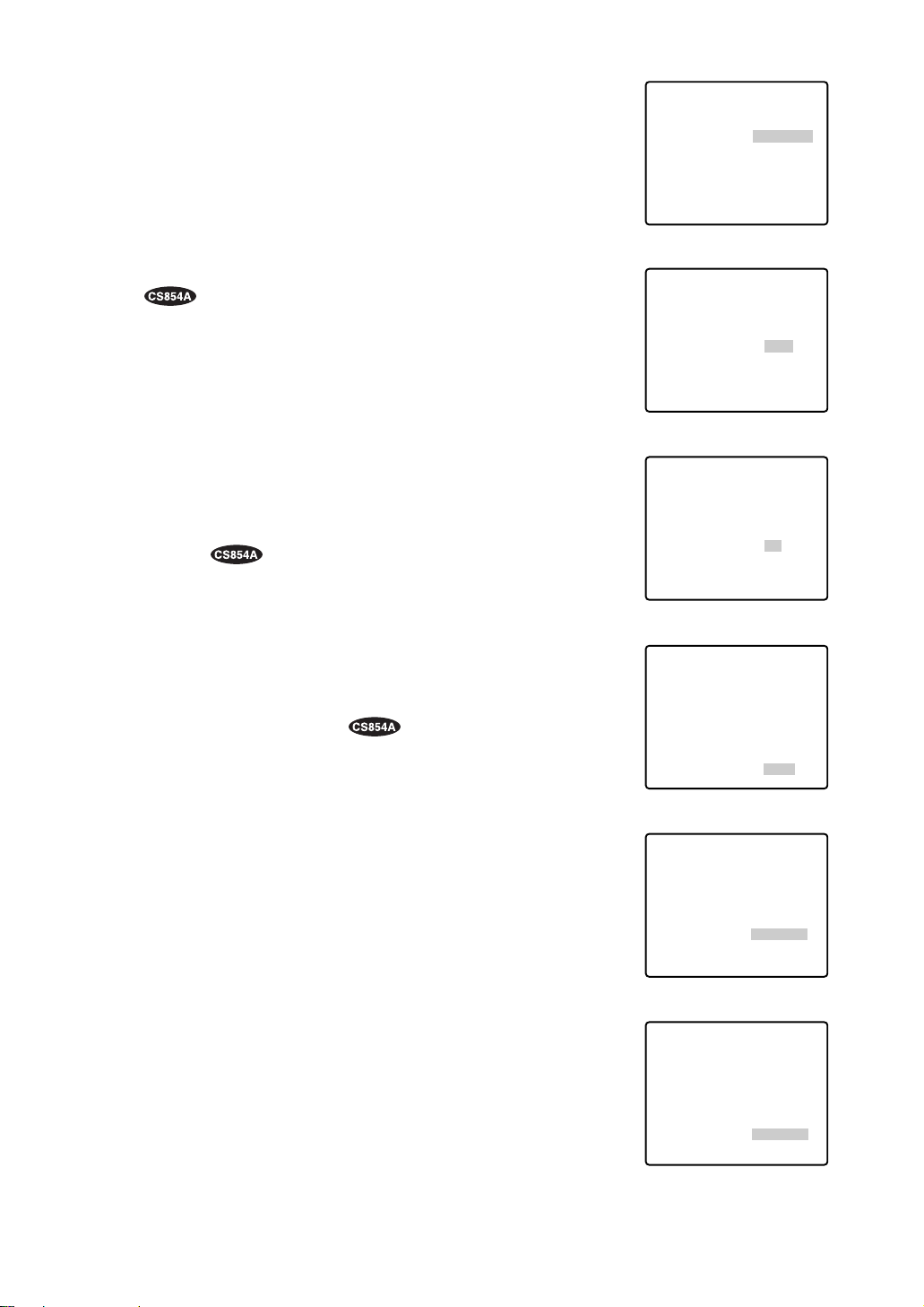
45
(4) Camera Phase (Hue) Setting (HUE)
1. Move the cursor to HUE. The “I” cursor appears in inversed video.
2. While observing the vector scope or color video monitor, adjust
the chroma phase (hue) by using the joystick. The cursor moves
to the right or left.
To reset to the factory setup, press the F2 button of the WVCU550B.
(For the WV-RM70, keep pressing the Right and Left switches
simultaneously for 2 seconds or more.)
(5) BW
Move the cursor to BW and select AUTO, ON or OFF by moving
the joystick to the right or left. Default : OFF
AUTO: The camera selects black and white mode if the picture is
dark, or color mode if the picture is bright enough.
Note: It takes 1 minute to make the selected mode effective
after stopping pan/tilt, zoom or focus.
ON: Black and white mode is selected.
OFF: Color mode is selected.
Note: Mode selection is disabled if ALARM IN 4 is set to B/W
on the Special 1 menu.
(6) BURST(BW)
Move the cursor to BURST(BW) and select ON or OFF by moving
the joystick to the right or left. Default : ON
ON: The burst signal is supplied along with the black and white
composite video.
OFF: The burst signal is not output.
Note: We recommend that you usually select ON.
(7) Digital Noise Reduction (DNR)
Move the cursor to DNR and select LOW1, LOW2, HIGH1 or
HIGH2 by moving the joystick to the right or left. Default: LOW2
LOW1: Selects a lower effect. The afterimage remains.
LOW2: Selects a lower effect. No afterimage.
HIGH1: Selects a higher effect. The afterimage remains.
HIGH2: Selects a higher effect. No afterimage.
(8) To Restore the Camera Default Position
Move the cursor to REFRESH by using the joystick and press the
F2 button of the WV-CU550B.
(For the WV-RM70, WV-CU360 or WV-CU161, keep pressing the
Right and Left switches simultaneously for 2 seconds or more.)
(9) Camera Resetting
Move the cursor to CAMERA RESET by using the joystick and
press the F3 button of the WV-CU550B.
The camera is reset to the factory preset parameters.
(For the WV-RM70, keep pressing the Right, Left and Set switches
simultaneously for 2 seconds or more. For the WV-CU360 or WVCU161, keep pressing the Right and Left switches and the numeric button 5 simultaneously for 2 seconds or more.)
** SPECIAL2 **
CHROMA GAIN
AP GAIN
PEDESTAL
HUE
BW
BURST(BW)
REFRESH
CAMERA RESET
DNR LOW2
RET
** SPECIAL2 **
CHROMA GAIN
AP GAIN
PEDESTAL
HUE
BW
BURST(BW)
REFRESH
CAMERA RESET
DNR LOW2
RET
** SPECIAL2 **
CHROMA GAIN
AP GAIN
PEDESTAL
HUE
BW
BURST(BW)
REFRESH
CAMERA RESET
DNR LOW2
RET
** SPECIAL2 **
CHROMA GAIN
AP GAIN
PEDESTAL
HUE
BW
BURST(BW)
REFRESH
CAMERA RESET
DNR LOW2
RET
** SPECIAL2 **
CHROMA GAIN
AP GAIN
PEDESTAL
HUE
BW
BURST(BW)
REFRESH
CAMERA RESET
DNR LOW2
RET
••••|••••
••••|••••
•|•••••••
••••|••••
- +
OFF
ON
→
PUSH SW
→
PUSH SW
••••|••••
••••|••••
•|•••••••
••••|••••
- +
AUTO
ON
→
PUSH SW
→
PUSH SW
••••|••••
••••|••••
•|•••••••
••••|••••
- +
OFF
ON
→
PUSH SW
→
PUSH SW
••••
••••|••••
|
•••••••
•
••••|••••
- +
OFF
ON
→
PUSH SW
→
PUSH SW
••••|••••
••••|••••
•|•••••••
••••|••••
- +
OFF
ON
→
PUSH SW
→
PUSH SW
|
••••
** SPECIAL2 **
CHROMA GAIN
AP GAIN
PEDESTAL
HUE
BW
BURST(BW)
REFRESH
CAMERA RESET
DNR LOW2
RET
••••|••••
••••|••••
•|•••••••
••••|••••
- +
OFF
ON
→
PUSH SW
→
PUSH SW
Page 45
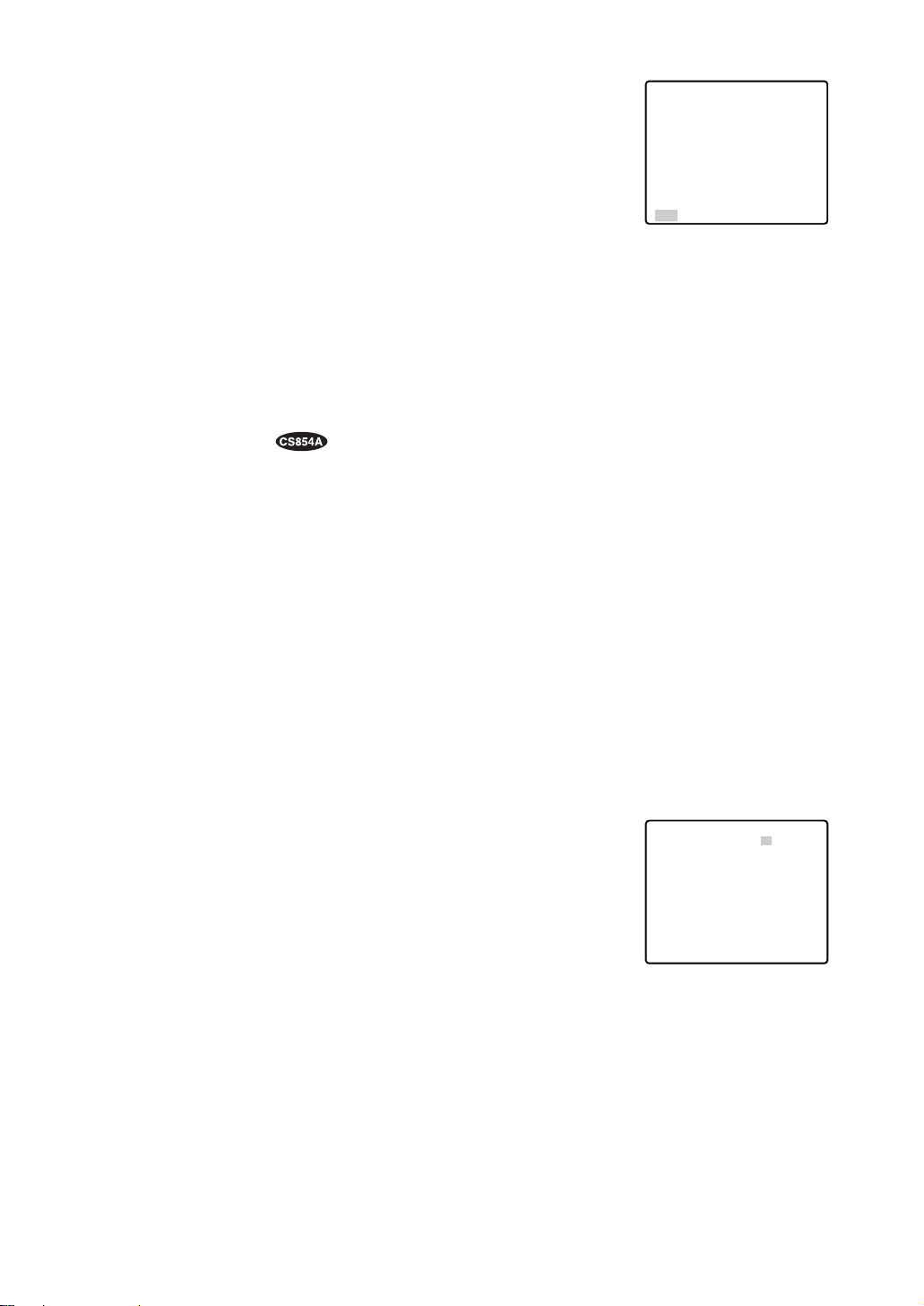
46
■ RS485 Setup
● Initial Camera Communication Parameters
In an RS485 chain the matrix switcher, PC, controllers and cameras should be set to the same protocol
and parameters for communication.
Confirm the system protocol and parameters prior to setting the communication parameters for the camera.
The initial communication parameters for WV-CS854A are shown on the RS485 setup menu below.
Other than the on-screen-setup parameters, the 4-bit DIP switch may be used to select 2-line (Half
Duplex) or 4-line (Full Duplex) communication.
● Changing the Camera Communication Parameters
You can remote control this camera by using a specified extension unit such as a computer with a
modem.
1. Display the SET UP MENU. Move the cursor to RS485 SET UP
and press the CAM (SET) key. RS485 SET UP menu appears on
the monitor.
2. Move the cursor to the item and select the parameter by moving
the joystick to the right or left.
UNIT NUMBER
Displays the unit number set by the DIP switch.
If the switch is set to 1-96, select a number by moving the joystick to the right or left.
In an RS485 chain each unit must have a unique number.
Default : 1. See INSTALLATION for DIP switch setting.
SUB ADDRESS
Do not set.
RS485 Setup menu
(10)To Close the SPECIAL2 (SPECIAL) Menu
Move the cursor to RET and press the CAM (SET) key.
The setup menu appears on the monitor screen.
Note:
How to Reset to the Factory Preset Parameters
Any of the above settings plus the ALC/MANUAL level control and
phase adjustments can be reset to the factory preset parameters by
placing the cursor over the desired mode and then press the F2 button of the WV-CU550B.
(For the WV-RM70, keep pressing the Right and Left switches simultaneously for 2 seconds or more.)
** SPECIAL2 **
CHROMA GAIN
AP GAIN
PEDESTAL
HUE
BW
BURST(BW)
REFRESH
CAMERA RESET
DNR LOW2
RET
••••
••••|••••
•|•••••••
••••|••••
- +
OFF
ON
→
PUSH SW
→
PUSH SW
|
••••
** RS485 SET UP **
UNIT NUMBER
SUB ADDRESS
BAUD RATE
DATA BIT
PARITY CHECK
STOP BIT
XON/XOFF
WAIT TIME
ALARM DATA
DELAY TIME
RET
1
1
19200
8
NONE
1
NOT USE
OFF
AUTO2
OFF
Page 46

47
BAUD RATE
Specifies the transmission speed (2 400, 4 800, 9 600, 19 200 bit per second) for the RS485 communication. The factory setting is 19 200.
DATA BIT
Specifies the number of data bits (7 or 8 bits) for the RS485 communication. The factory setting is 8.
PARITY CHECK
Specifies the parity check mode (NONE, ODD, EVEN). The factory setting is NONE.
STOP BIT
Specifies the number of stop bits (1 or 2 bits). The factory setting is 1.
X ON/X OFF
Specifies whether to apply flow control or not (NOT USE, USE). The factory setting is NOT USE.
WAIT TIME
Specifies the time to wait until retrying after confirming that no data is received from the controller. (OFF:
no transmission, 100, 200, 400, 1 000 ms).
ALARM DATA
Specifies alarm transmission mode depending on the protocol selected by the 8-bit DIP switch.
POLLING: Transmits the alarm data in response to requests from the controller.
AUTO 1: Transmits the alarm data each time an alarm signal is received in the camera.
AUTO 2 (Default): Transmits alarm data at intervals of at least 5 seconds.
DELAY TIME
Specifies the time to transmit the acknowledge request when communicating on a 2-line connection.
(OFF, 10, 20, 40, 100 ms) Default : OFF.
This menu appears only when a 2-line communication is used. Make sure to be 100 ms when connecting
the camera with the WJ-FS616 Video Multiplexer in a 2-line communication system.
The settings become effective with the closing of the SET UP MENU.
Note: Set the same parameters for the cameras, controllers and personal computers in an RS485 chain.
Page 47

48
• The following steps of installation and connection should be taken by qualified service personnel or
system installers and should conform to all local codes.
• Make sure to switch the camera off before installation and connection.
• Do not install the camera near the air outlet of an air conditioner.
Camera mounting base
Camera
Camera mounting
base
Fixing screw
Loosen and
push
1234
ON
1234ON5678
8-bit DIP SW
4-bit DIP SW
INSTALLA TION
1. Disassembling the Camera
(1) Loosen the fixing screw to separate the
camera mounting base and the camera.
Push up the screwdriver once before
removing the screw.
(2) Turn the camera mounting base ap-
proximately 15 degrees counterclockwise and remove the base from the
camera.
2. Setting the Switches
There are two DIP switches on the camera:
an 8-bit switch and a 4-bit switch. The 8-bit
DIP switch is used in both ways to return to
the factory default settings and to specify
the unit number. The 4-bit DIP switch
selects termination ON/OFF and half/full
duplex selection for RS485 communications.
Switch settings are read in to the camera
when the power is turned on. Make sure to
turn it off, then turn it back on after changing
the switch settings. Switch positions and
functions are shown below.
RS485 Parameter Setup
The selected protocol, communication parameters, and set unit numbers are read into
the camera when power is switched on.
1. Switch off the camera.
2. Set the switch according to the function
shown in the table.
3. Switch on the camera to read in the
changed switch settings.
4. Switch off the camera.
5. Set the unit number with the DIP switch
(see next page).
6. Switch on the camera to read in the
changed switch settings.
Note: The changed communication
parameters are displayed on the
RS485 SETUP menu after the camera has been switched on.
Precautions
15°
Turn 15°
Then
Camera
mounting base
Remove
from the
camera
1234ON5678
Switch position
Returns to the factory default settings.
1234ON5678
1234ON5678
1234ON5678
Switch position
Parameter selection
Baud rate
1
1
1
None
None
None
8
8
8
19 200
9 600
4 800
Data bit
Parity
check
Stop
bit
Page 48

49
Unit Number
Switch 1, an 8-bit DIP switch, specifies unit number or returns to
the factory default settings for Panasonic’s protocol.
When the unit number 1-96* is selected, it should be set on the
RS485 SETUP menu (see page 46).
1234ON5678
8-bit DIP SW
For Panasonic’s Protocol
1234ON5678
Switch position
Unit
number
1234ON5678
1234ON5678
1234ON5678
1234ON5678
1234ON5678
1234ON5678
1234ON5678
1234ON5678
1234ON5678
1234ON5678
1234ON5678
1234ON5678
1234ON5678
1234ON5678
1234ON5678
1234ON5678
1234ON5678
1234ON5678
1234ON5678
1234ON5678
1234ON5678
1234ON5678
1234ON5678
1234ON5678
1234ON5678
1234ON5678
1234ON5678
1234ON5678
1234ON5678
1234ON5678
1234ON5678
Switch position
Unit
number
Switch position
Unit
number
1-96*
1
2
3
4
5
6
7
8
9
10
11
12
13
14
15
16
17
18
19
20
21
22
23
24
25
26
27
28
29
30
31
32
33
34
35
36
37
38
39
40
41
42
43
44
45
46
47
48
49
50
51
52
53
54
55
56
57
58
59
60
61
62
63
64
65
66
67
68
1234ON5678
1234ON5678
1234ON5678
1234ON5678
1234ON5678
1234ON5678
1234ON5678
1234ON5678
1234ON5678
1234ON5678
1234ON5678
1234ON5678
1234ON5678
1234ON5678
1234ON5678
1234ON5678
1234ON5678
1234ON5678
1234ON5678
1234ON5678
1234ON5678
1234ON5678
1234ON5678
1234ON5678
1234ON5678
1234ON5678
1234ON5678
1234ON5678
1234ON5678
1234ON5678
1234ON5678
1234ON5678
1234ON5678
1234ON5678
1234ON5678
1234ON5678
1234ON5678
(to be continued)
Page 49

50
1234ON5678
Switch position
Unit
number
1234ON5678
1234ON5678
1234ON5678
1234ON5678
1234ON5678
1234ON5678
1234ON5678
1234ON5678
1234ON5678
1234ON5678
1234ON5678
1234ON5678
1234ON5678
1234ON5678
1234ON5678
1234ON5678
1234ON5678
Switch position
Unit
number
Switch position
Unit
number
69
70
71
72
73
74
75
76
77
78
79
80
81
82
83
84
85
86
87
88
89
90
91
92
93
94
95
1234ON5678
1234ON5678
1234ON5678
1234ON5678
1234ON5678
1234ON5678
1234ON5678
1234ON5678
1234ON5678
Page 50

51
BP 2
Switch
position
BP 1 Function
Function
Switch
position
RS485 Setting
The 4-bit DIP switch in used for
RS485 termination.
ON
1. Mark the mounting holes on the ceiling,
using the removed camera mounting base
as a template.
2. Fix the camera mounting base to the ceiling
with four screws (not provided, M4).
Note: Remove sharp edges to protect the
cables.
3. Assemble the Camera
Reverse the disassembly procedure. Take
care not to cut any cables.
OFF
Termination ON
Termination OFF *
b. Top Cable Exit
Prepare a hole in the ceiling board to run
the cables.
BP 3 BP 4
ON ON ON
OFF OFF OFF
Half duplex (2 line)
Full duplex (4 line) *
Notes:
• Defaults are marked with
*.
• BP stands for Bit Position.
• Daisy chain connection is not available for
Full Duplex. (Only for Panasonic’s system
controllers)
Be sure to select a ceiling board strong
enough to support 4 times the total weight of
the camera.
Precaution
a. Sideway Cable Exit
Prepare a cutout in the diecast case and
decoration cover as shown in the following
figures.
Cutout in Diecast Case
Cutout in Decoration Cover
4-bit DIP SW
ON
1234
Marking
Page 51

52
5. Tighten the fixing screw M3 (provided).
Notes :
(1) Tighten the camera fixing screw with a
screwdriver.
(2) Follow the instructions given here to
ensure that the camera and camera
mounting base are installed safely.
(3) When removing the camera from the
camera mounting base, loosen and
press up the camera fixing screw (M3)
by using a screwdriver.
6. Fix the decoration cover to the camera
mounting base.
a. Sideway Cable Exit
Pass the cables through the cutout made in
the diecast case and decoration cover.
b. Top Cable Exit
Push the decoration cover against the camera mounting base.
Cautions:
• Use the supplied dust protection sheet if the
camera mounting base is liable to be
exposed to a dusty atmosphere. Remove
the cover from the dust protection sheet,
then stick the sheet on the camera mounting
base.
• Remove the sheet before mounting the camera on the base.
• While the camera is separated from the
base, keep the camera in the supplied polyethylene sack.
4. Mount the camera on the camera mounting
base and rotate the camera clockwise.
3. Hook the Fall prevention wire on the camera
mounting base.
Be sure to match the wire with the fall
prevention wire fixing angle as shown below.
Ring of the
fall prevention
wire
Fall prevention
wire fixing angle
15°
Page 52

53
#24
(0.22mm
2
)
Copper wire size
(AWG)
Length
of cable
(approx.)
(m)
(ft)
#22
(0.33mm
2
)
#20
(0.52mm2)
#18
(0.83mm2)
20 30 45 75
65 100 160 260
Accessory Connector Information
Pin no. Power source
1
2
3
4
24 V AC LIVE
24 V AC NEUTRAL
Ground
Not use
Prepare the individual conductors for clamping.
Use MOLEX band tool part number 57027-5000
(for UL-Style Cable UL1015) or 57026-5000 (for
UL-Style UL1007) for clamping the contacts.
After clamping the contacts, push them into the
proper holes in the accessory connector of this
camera until they snap in place.
• Shrinking the cable-entry seal is a onetime procedure. Do not shrink the cableentry seal until it has been ascertained
that the unit is functioning.
CONNECT THIS TO 24 V AC CLASS 2
POWER SUPPLY ONLY.
• To prevent fire or electric shock hazard,
use a UL listed cable (VW-1, style 1007)
should be used for the cable for the 24 V
AC Input Terminals.
p
Up
Wire
Contact
Up
Contact
Wire
Approx.
3 mm (0.1 inch)
Insert the wire until A position
and clamp the contacts.
• 24 V AC Power Supply Connection
Recommended wire gauge sizes for 24 V AC line.
CAUTIONS
Note: When powered up, the unit performs a self-check (including one panning, tilting, zooming and
focusing operation).
✻ The coaxial cable length (RG-59/U, BELDEN 9259) for the connection is up to
900 meters (3,000 ft.)
To VIDEO IN
(CAMERA IN)
Video output
24 V AC
BNC plug
Coaxial cable
RS485 cable
Data port
CONNECTIONS
BNC plug
Alarm in
Alarm out
To sensors
To indicators
• The following connections should be made by qualified service personnel or system installers in
accordance with NEC 725-51.
• Make sure to switch the camera off before installation or connection.
Precautions
24 V AC cable
How to Assemble the Cable with the
Accessory Connector
Strip back the cable jacket approx. 3 mm (0.1
inch) and separate the individual conductors.
3
4
1
2
Approx.
Contact
Up
0.1 inch
A
Insert
Insert the wire until A position
and clam
Wire
the contacts.
Up
Contact
Wire
Page 53

54
Gray
White
Pink
Yellow green or light blue
Black
Brown
Red
Orange
Yellow
Light blue or green
Blue
Purple
Wire color
Wire color
• RS485 Connection
Note:
Use the cable that is described below for RS485 site communication.
• Shielded, twisted pair cable
• Low impedance
• Wire gauge size is thicker than AWG #22 (0.33 mm
2
).
• ALARM IN Connections
An 8-pin and a 4-pin harness are supplied with the camera as standard accessories. Connect external sensors to this connector. Input specifications are low-active, non-voltage contact (ON when
active) or open collector (Low when active). The table below shows wire colors versus pin functions.
Note: Use a relay if the voltage or current of the connected device exceeds the ratings.
• ALARM OUT Connections
Connect an external device, for example, a buzzer or lamp, to this connector. Output specifications
are low-active, open-collector and a drive capacity of 16 V DC 100 mA maximum. The table below
shows wire colors versus pin functions.
Function
OUT 1
GND
OUT 2
GND
Alarm OUT (4-pin)
Function
IN 1
GND
IN 2
GND
IN 3
GND
IN 4
GND
Alarm IN (8-pin)
Data transmission
Data reception
Brown
Red
Orange
Yellow
Green
GND
T (B)
T (A)
R (B)
R (A)
Page 54

55
550
550
550
550
Max. 64 cameras
VCRs (up to 16)
Monitors (up to 16)
Printer
System controller
Combination camera
Matrix
switcher
Personal computer
RS-232C port
System status
monitor
Alarm inputs
Note: When any peripheral is turned off and turned on again, the camera is also turned off and turned
back on.
SYSTEM CONNECTIONS
ALARM BUSY
F3 F4F2F1
IRIS
ACK
BACK
FORWARD
CLOSEOPEN
PRESET
RESET
SEQ
SEQ ALT
1 2 3
4 5 6
AF
AUX
DEC
INC
FOCUS
ZOOM
7 8 9
12
–1CAM
+1CAM STOP
NEAR
TELE
MON CAM
0
FARWIDE
ESC SET
System Controller WV-CU550
LEFT RIGHT
ALARM BUSY
UP
DOWN
B
F3 F4F2F1
IRIS
ACK
BACK
FORWARD
CLOSEOPEN
PRESET
RESET
SEQ
SEQ ALT
1 2 3
4 5 6
AF
AUX
DEC
INC
FOCUS
ZOOM
7 8 9
12
–1CAM
+1CAM STOP
NEAR
TELE
MON CAM
0
FARWIDE
ESC SET
System Controller WV-CU550
LEFT RIGHT
DOWN
ALARM BUSY
UP
B
F3 F4F2F1
IRIS
ACK
BACK
FORWARD
CLOSEOPEN
PRESET
RESET
SEQ
SEQ ALT
1 2 3
4 5 6
AF
AUX
DEC
INC
FOCUS
ZOOM
7 8 9
12
–1CAM
+1CAM STOP
NEAR
TELE
MON CAM
0
FARWIDE
ESC SET
System Controller WV-CU550
LEFT RIGHT
ALARM BUSY
UP
DOWN
B
F3 F4F2F1
UP
IRIS
ACK
BACK
FORWARD
CLOSEOPEN
PRESET
RESET
SEQ
SEQ ALT
1 2 3
LEFT RIGHT
4 5 6
AF
AUX
DEC
INC
FOCUS
ZOOM
7 8 9
12
–1CAM
DOWN
+1CAM STOP
NEAR
TELE
MON CAM
0
FARWIDE
ESC SET
System Controller WV-CU550
B
Page 55

56
approx. 6 s (FAR/NEAR) in manual mode
WV-CS854A
Minimum illumination
Bright object
Smear
When the camera is aimed at a bright light, such
as a spotlight, or a surface that reflects bright
light, smear or blooming may appear. Therefore,
the camera should be operated carefully in the
vicinity of extremely bright objects to avoid
smear or blooming.
● General
● Lens
WV-CS854A WV-CS554
Power required
Power consumption
Pick-up device
Scanning area
Scanning system
Scanning frequency
Synchronization
Video output
Resolution (at center)
Signal-to-noise ratio
Dynamic range
Ambient operating temperature
Dimensions
Weight
24 V AC, 60 Hz
WV-CS554
Zoom ratio
Focal length
Maximum aperture ratio
Iris range
Angular field of view
Zoom speed
Focus speed
22 times + digital zoom x 10
3.79 mm - 83.4 mm
1 : 1.6 (WIDE) - 1 : 3.0 (TELE)
F1.6 - F22, close
horizontal: 2.6˚ - 51.7˚, vertical: 2.0˚ - 39.9˚
approx. 4.5 s (TELE/WIDE) in manual mode approx. 7.5 s
22 times + digital zoom x 2
14 W
755 (H) x 485 (V) pixels, interline transfer CCD
3.59 (H) x 2.70 (V) mm (equivalent to scanning area of 1/4” pick-up tube)
2 : 1 interlace
horizontal: 15.734 kHz, vertical: 59.94 Hz
internal, line-locked or multiplexed vertical drive (VD2) selectable
1.0 V[p-p] composite / 75 Ω
horizontal: more than 480 lines
(C/L mode), more than 570
lines (B/W mode)
vertical: more than 350 lines
more than 50 dB (AGC Off, weight on)
46 dB Super-D2 On
1.0 lx (0.1 foot-candle) at C/L mode,
0.06 lx (0.006 foot-candle) at B/W mode
with 2 times sensitivity up (AGC HIGH)
–10˚C - +50˚C (14˚F - 122˚F)
120 mm (D) x 191 mm (H) [4-3/4” (D) x 7-1/2” (H)]
2 kg (4.4 lbs)
2.0 lx (0.2 foot-candle)
horizontal: more than 480 lines
vertical: more than 350 lines
SPECIFICATIONS
PREVENTION OF BLOOMING AND SMEAR
Page 56

57
Image Hold
Proportional pan/tilt
Tilting speed
Alarm input/output
—
—
—
manual: approx.1˚/s - 24˚/s, 8-steps/
16-steps
sequence mode: maximum approx.
300˚/s
Weight and dimensions indicated are approximate.
Specifications are subject to change without notice.
● Pan / Tilt
WV-CS854A WV-CS554
Panning range
Panning angle setting
Panning mode
Panning speed
Tilting range
Tilting mode
360˚ endless
possible (in auto pan mode)
manual, sequence, sort, auto pan
manual: approx. 0.1˚/s - 120˚/s,
8-steps/64-steps
sequence mode: maximum approx.
300˚/s
manual: approx.1˚/s - 24˚/s, 8-steps/
16-steps
sequence mode: maximum approx.
300˚/s
0˚ - 180˚ 0˚ - 90˚
manual, sequence, sort
manual: approx. 0.1˚/s - 120˚/s,
8-steps/64-steps
sequence mode: maximum approx.
300˚/s
● Functions
WV-CS854A WV-CS554
Control interface
Preset control
Titles (ID)
Auto focus
Electronic shutter
Electronic sensitivity up
Super-D2
B/W mode
Auto mode
Auto pan key
Digital flip
Privacy zone
Motion detector
DNR
multiplexed control data or RS-485
64 preset positions 8 preset positions
preset ID, camera ID, area title: up to
16 characters
manual / auto
1/60 (Off), 1/100, 1/250, 1/500, 1/1 000, 1/2 000, 1/4 000, 1/10 000 s
AGC On (LOW)/On (MID)/On/(HIGH)/Off On / Off
max. 32 times, auto / fixed
On / Off
auto / On / Off
Off / sequence / sort / auto pan / patrol Off / sequence / sort / auto pan
sequence / sort / auto pan / patrol
On / Off
On / Off, up to 8 zones
On / Off
4-input (ALARM 1 - 4), 2-output
(ALARM/AUX1, B/W/AUX2)
On / Off
On / Off
LOW1 / LOW2 / HIGH1 / HIGH2
—
—
—
—
—
—
preset ID, camera ID: up to 16 characters
multiplexed control data
Page 57

58
ACCESSORIES
OPTIONAL ACCESSORIES
Decoration cover .................................................. 1 pc.
Alarm in cable ....................................................... 1 pc.
Alarm out cable .................................................... 1 pc.
Connector for 24 V AC .......................................... 1 pc
Dome cover (approx. 60 % transparency, smoked type) ...................... WV-CS2S
Dome cover (approx. 50 % transparency, smoked type) ...................... WV-CS2SH
Dome cover (approx. 70 % transparency, metal type) .......................... WV-CS2M
Page 58

59
Selecting a PRESET position From #1 to #64
#1 [1] + [CAM FUNC]
#10 [1] + [0] + [CAM FUNC]
#64 [6] + [4] + [CAM FUNC]
AUTO PAN
ON [6] + [5] + [CAM FUNC]
OFF [6] + [6] + [CAM FUNC]
Speed Up [6] + [7] + [CAM FUNC]
Speed Down [6] + [8] + [CAM FUNC]
Setting Start Point [6] + [9] + [CAM FUNC]
Setting End Point [7] + [0] + [CAM FUNC]
Setting PAN Reverse [7] + [4] + [CAM FUNC]
AUTO MODE
MODE Off [7] + [1] + [CAM FUNC]
SEQ On [7] + [2] + [CAM FUNC]
SORT On [7] + [3] + [CAM FUNC]
ENDLESS PAN
On [7] + [6] + [CAM FUNC]
Off [7] + [7] + [CAM FUNC]
DIGITAL FLIP
On [7] + [8] + [CAM FUNC]
Off [7] + [9] + [CAM FUNC]
PROP. PAN/TILT
On [8] + [0] + [CAM FUNC]
Off [8] + [1] + [CAM FUNC]
SUPER-D2
On [8] + [4] + [CAM FUNC]
Off [8] + [5] + [CAM FUNC]
AUTO FOCUS
STOP AF On* [8] + [6] + [CAM FUNC]
STOP AF Off* [8] + [7] + [CAM FUNC]
AF On (Activate) [8] + [8] + [CAM FUNC]
HOME POSITION
Move to HOME [8] + [9] + [CAM FUNC]
B/W or C/L
B/W On* [9] + [0] + [CAM FUNC]
B/W Off* [9] + [1] + [CAM FUNC]
B/W AUTO* [9] + [2] + [CAM FUNC]
CAMERA ID
On [9] + [3] + [CAM FUNC]
Off [9] + [4] + [CAM FUNC]
AREA TITLE
NESW On [9] + [5] + [CAM FUNC]
USER On [9] + [6] + [CAM FUNC]
TITLE Off [9] + [7] + [CAM FUNC]
EL-ZOOM
On [9] + [8] + [CAM FUNC]
Off [9] + [9] + [CAM FUNC]
RESTART
Begin [1] + [0] + [0] + [CAM FUNC]
Memorize PRESET From #1 to #64**
Position #1 [1] + [0] + [1] + [CAM FUNC]
Position #10 [1] + [1] + [0] + [CAM FUNC]
Position #64 [1] + [6] + [4] + [CAM FUNC]
PATROL
PLAY [1] + [6] + [5] + [CAM FUNC]
STOP [1] + [6] + [6] + [CAM FUNC]
LEARN(Start) [1] + [6] + [7] + [CAM FUNC]
IRIS
Open [1] + [6] + [9] + [CAM FUNC]
Close [1] + [7] + [0] + [CAM FUNC]
EL-SHUTTER
On [1] + [7] + [1] + [CAM FUNC]
Off [1] + [7] + [2] + [CAM FUNC]
Speed Up [1] + [7] + [3] + [CAM FUNC]
Speed Down [1] + [7] + [4] + [CAM FUNC]
AGC
On [1] + [7] + [5] + [CAM FUNC]
Off [1] + [7] + [6] + [CAM FUNC]
SENS UP
On [1] + [7] + [7] + [CAM FUNC]
Off [1] + [7] + [8] + [CAM FUNC]
Up [1] + [7] + [9] + [CAM FUNC]
Down [1] + [8] + [0] + [CAM FUNC]
SENS UP AUTO
On [1] + [8] + [1] + [CAM FUNC]
Off [1] + [8] + [2] + [CAM FUNC]
Up [1] + [8] + [3] + [CAM FUNC]
Down [1] + [8] + [4] + [CAM FUNC]
LL SYNC phase
INC [1] + [8] + [5] + [CAM FUNC]
DEC [1] + [8] + [6] + [CAM FUNC]
PAN
180° turn [1] + [8] + [7] + [CAM FUNC]
CLEANING
On [1] + [8] + [8] + [CAM FUNC]
Off [1] + [8] + [9] + [CAM FUNC]
BW SW AUTO
30 sec. [1] + [9] + [0] + [CAM FUNC]
60 sec. [1] + [9] + [1] + [CAM FUNC]
300 sec. [1] + [9] + [2] + [CAM FUNC]
600 sec. [1] + [9] + [3] + [CAM FUNC]
Function
APPENDIX
Shortcuts
Shortcut operations are available to controllers having the CAM FUNCTION key. Pressing numeric key(s)
for one digit up to three digits then CAM FUNCTION key implements the respective functions as follows.
The CAM FUNCTION key is abbreviated to [CAM FUNC] here.
Key Function Key
Notes:
• Shortcut operations marked with * will change parameter settings only. Actual operation takes place
when the conditions for the changed settings are met.
• As entering shortcuts marked with **, “NO REGS. ; FLIP ON” may appear on the monitor. Re-enter the
shortcut.
• Shortcuts may be ignored while PAN/TILT, ZOOM or FOCUS is in operation.
• PATROL LEARN saves only [1] through [6]+[4], [1]+[6]+[9] and [1]+[7]+[0] in the memory.
• PATROL PLAY stops when a shortcut other than [1]+[6]+[9] or [1]+[7]+[0] is entered.
Page 59

N0701-1071 V8QA5748BN Printed in Japan
Imprimé au Japon
2001 © Matsushita Communication Industrial Co., Ltd.
Panasonic Canada Inc.
5770 Ambler Drive, Mississauga,
Ontario, L4W 2T3 Canada (905)624-5010
Panasonic Sales Company
Division of Matsushita Electric of Puerto Rico Inc.
Ave. 65 de Infanteria. Km. 9.5
San Gabriel Industrial Park, Carolina,
Puerto Rico 00985 (809)750-4300
Panasonic Security and Digital Imaging Company
A Division of Matsushita Electric Corporation of America
Executive Office: One Panasonic Way 3E-7, Secaucus, New Jersey 07094
Regional Offices:
Northeast: One Panasonic Way, Secaucus, NJ 07094 (201) 348-7303
Southern: 1225 Northbrook Parkway, Suite 1-160, Suwanee,
GA 30024 (770) 338-6838
Midwest: 1707 North Randall Road, Elgin, IL 60123 (847) 468-5211
Western: 6550 Katella Ave., Cypress, CA 90630 (714) 373-7840
 Loading...