

Panasonic WV-CS554, WV-CS854 Operating Instructions Manual
Before attempting to connect or operate this product,
please read these instructions carefully and save this manual for future use.
Model No. WV-CS554
WV-CS854
Combination Camera
Operating Instructions
ENGLISH
FRANÇAIS
CONTENTS
PREFACE ....................................................... 3
FEATURES ..................................................... 3
PRECAUTIONS .............................................. 4
CONSTRUCTION ........................................... 5
SETUP ............................................................ 6
■ Setup Menu ............................................ 6
■ Setup Menu Description ........................ 9
SETTING PROCEDURES ............................... 14
■ Menu Display .......................................... 14
■ Preset ...................................................... 15
■ Deleting Preset Positions ........................ 20
■ Home Position Setting ............................. 20
■ Self Return Setting .................................. 20
■ Auto Mode Setting .................................. 21
■ AUTO PAN KEY Setting .......................... 22
■ DIGITAL FLIP ON/OFF ............................ 22
■ LOCAL/REMOTE Setting ........................ 23
■ SPECIAL 1 ............................................... 23
■ Camera Setting ...................................... 32
■ RS485 Set Up ............................ 43
INSTALLATION .............................................. 45
CONNECTIONS ............................................. 51
SYSTEM CONNECTIONS .............................. 53
PREVENTION OF BLOOMING
AND SMEAR .................................................. 54
SPECIFICATIONS .......................................... 54
ACCESSORIES .............................................. 55
OPTIONAL ACCESSORIES ........................... 55
APPENDIX ...................................................... 56
The serial number of this product may be found
on the top of the unit.
You should note the serial number of this unit in
the space provided and retain this book as a permanent record of your purchase to aid identification in the event of theft.
Model No.
Serial No.
WARNING:
To reduce the risk of fire or electric shock, do not expose this appliance to rain or moisture.
The lightning flash with arrowhead symbol, within an equilateral triangle, is intended to alert the
user to the presence of uninsulated "dangerous voltage" within
the product's enclosure that may
be of sufficient magnitude to constitute a risk of electric shock to
persons.
The exclamation point within an
equilateral triangle is intended to
alert the user to the presence of
important operating and maintenance (servicing) instructions in
the literature accompanying the
appliance.
CAUTION: TO REDUCE THE RISK OF ELECTRIC SHOCK,
DO NOT REMOVE COVER (OR BACK).
NO USER-SERVICEABLE PARTS INSIDE.
REFER SERVICING TO QUALIFIED
SERVICE PERSONNEL.
CAUTION
RISK OF ELECTRIC SHOCK
DO NOT OPEN
SA 1965
SA 1966
NOTE: This equipment has been tested and
found to comply with the limits for a Class A digital device, pursuant to Part 15 of the FCC Rules.
These limits are designed to provide reasonable
protection against harmful interference when the
equipment is operated in a commercial environment. This equipment generates, uses, and can
radiate radio frequency energy and, if not
installed and used in accordance with the instruction manual, may cause harmful interference to
radio communications.
Operation of this equipment in a residential area
is likely to cause harmful interference in which
case the user will be required to correct the interference at his own expense.
FCC Caution: To assure continued compliance,
(example - use only shielded interface cables
when connecting to computer or peripheral
devices). Any changes or modifications not
expressly approved by the party responsible for
compliance could void the user’s authority to
operate this equipment.
For U.S.A
2
3
Panasonic presents highly advanced CCTV technology that meets the demands of new and everchangeing applications.
This high-performance combination color camera is utilized as a video surveillance device. The
camera incorporates the Super-Dynamic2
Digital Signal Processor, pan-tilt mechanism and
• High quality picture of 755 x 485 pixels.
• Super Dynamic2 extends the dynamic
range up to 46 dB.
• Minimum illumination of 1 lx for color, 0.06 lx
for black and white , or 2 lx .
• 64 preset positions for , 8 preset
positions for .
• Auto Black/White mode enables the camera
to switch between C/L and B/W in response
to input lights.
• Digital Flip allows a 180 degree tilting to
trace passing objects right under the camera.
• Privacy zone settings veil unwanted zones
so as not to be displayed on the monitor.
• A run of manual operations is memorized in
PATROL LEARN for repetitive use in future.
• Built-in digital motion detector and alarm output.
• Protocol adaptability to Panasonic’s conventional and new generation protocols.
PREF ACE
FEATURES
22 times zoom lens in a compact enclosure. A
newly developed 1/4-inch CCD is employed for
use under extremely low light conditions. It also
assures clear display of pictures in which bright
and dark objects coexist without mutual interference thanks to the Super-D2 DSP.
ENGLISH
Symbols Used in this instructions
This operating instructions is included both of the
combination cameras WV-CS554 and WVCS854.
It uses the icons shown below to describe the
functions available with each model.
Functions only with the WV-CS554
Combination Camera
Functions only with the WV-CS854
Combination Camera

4
1. Do not attempt to disassemble the camera.
To prevent electric shock, do not remove
screws or covers.
There are no user serviceable parts inside.
Ask a qualified service person for servicing.
2. Handle the camera with care.
Do not abuse the camera. Avoid striking,
shaking, etc. The camera could be damaged by improper handling or storage.
3. Do not expose the camera to rain or moisture, or try to operate it in wet areas.
This product is designed for indoor use or
locations where it is protected from rain and
moisture.
Turn the power off immediately and ask a
qualified service person for servicing.
Moisture can damage the camera and also
create the danger of electric shock.
4. Do not use strong or abrasive detergents
when cleaning the camera body.
Use a dry cloth to clean the camera when
dirty.
In case the dirt is hard to remove, use a mild
detergent and wipe gently. Care should be
taken not to scratch the dome when wiping
it.
5. Never face the camera towards the sun.
Do not aim the camera at bright objects.
Whether the camera is in use or not, never
aim it at the sun or other extremely bright
objects. Otherwise, blooming or smear may
be caused.
6. Do not install this camera upside down
This camera is designed for mounting on the
ceiling or wall. Using this camera installed
upside down, for example, mounted on the
floor, may cause malfunction.
7. If “OVER HEAT” sign appears on the
monitor screen
The temperature inside the camera exceeds
the normal level because of a malfunction of
the cooling fan etc. Turn the power off immediately and refer servicing to qualified service personal.
8. Do not operate the camera beyond the
specified temperature, humidity or power
source ratings.
Use the camera under conditions where
temperature is between −10°C - +50°C (14°F
- 122°F), and humidity is below 90%. The
input power source is AC 24V.
9. Do not install the camera near the air outlet of an air conditioner.
The lens may become cloudy due to condensation if the camera is used under the
following conditions.
• Rapid temperature fluctuations by
switching the air conditioner on and off.
• Rapid temperature fluctuations due to
frequent door opening and closing.
• Use in an environment where eyeglasses become foggy.
• Use in a room filled with cigarette smoke
or dust.
If the lens becomes cloudy due to condensation, remove the dome cover and
wipe all moist surfaces with a soft cloth.
10. Consumables
Parts having contacts such as the lens-drive
motors, cooling fan motor and slip-rings built
inside the camera are subject to wear with
time. About replacement and maintenance
of such parts, please ask the nearest service
center.
To prevent fire or electric shock hazard, the
UL listed wire, VW-1, style 1015, AWG 18 or
UL listed power supply cord, type SJT should
be used for the cable for 24V AC input terminals.
CAUTION
PRECAUTIONS
5
w
e
r
t
q
yu
o
i
!0
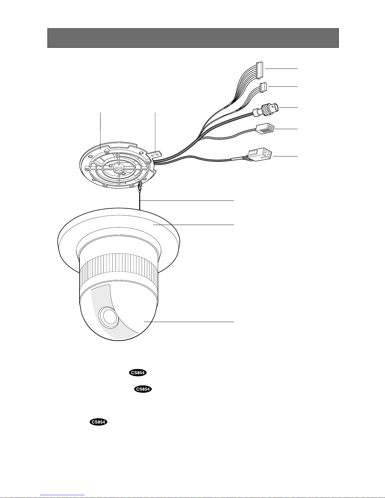
y Camera Mounting Base
u Panning Start Point
i Fall Prevention Wire
o Decoration Cover
!0 Dome Cover
q Alarm Input Connector
w Alarm Output Connector
e Video Output Connector
r Data Port
t Power Cable
CONSTRUCTION
7
Shutter
Speed
Selection
AGC
ON/OFF
Sensitivity
Up
ON/OFF
WHITE
BAL
AWC ATW
Super-D2
OFF
Light
Control
ALC/MANUAL
Super-D2
ON
Manual
Level
Adjustment
(Contrast)
Manual
Mask
Area
Selection
INT
Manual
Selection
VD2
Automatic
Selection
Manual
Level
Adjustment
Manual
Level
Adjustment
V-phase
Manual
Adjustment
LL
Manual
Selection
Motion
Detector
ON/OFF
Manual
Mask
Area
Selection
Manual
Level
Adjustment
Camera
Menu
CAMERA ID
Editing
CAMERA ID
Display
Position
Sync
INT/LL
Camera
Reset
Setting
Hue
Adjustment
Pedestal
Adjustment
AP
Gain
Adjustment
Chroma
Gain
Adjustment
Stop
Bit
Selection
Parity
Check
Selection
Data
Bit
Selection
BAUD
Rate
Selection
SubAddress
Selection
Delay Time
Selection
Xon/Xoff
Selection
Alarm
Data
Selection
Wait
Time
Selection
RS-485
Setup
Unit
Number
Selection
RS-485
Setup
To
A
A
Special
2
Burst
ON/OFF
Selection
Refresh
Setting
B/W
Selection
To
B
AF MODE
Selection
B
6
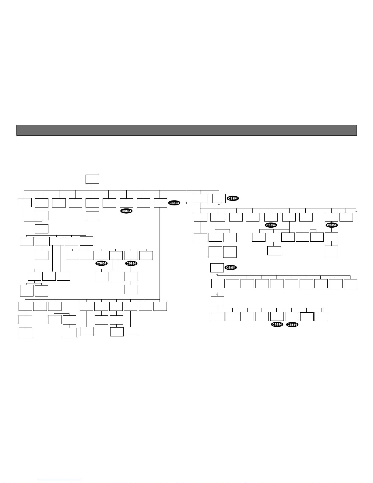
■ Setup Menu
Setup menus are shown in the diagram below. Various kinds of setup are available to have the camera
fulfill your requirements. Menus are built in a hierarchical structure from the Setup menu at the top down
to Manual Mask Area Selection at the bottom.
These menus are described in the following pages for reference prior to setup.
Switches, keys and the joystick are used for setup operations.
SETUP
Setup
Menu
Home
Position
Selection
Self
Return
Setting
Auto Pan
Key
Setting
Digital
Flip
ON/OFF
Local/
Remote
Selection
PRESET
Menu
Auto-Pan
Setting
Menu
Preset
Alarm
ON/OFF
EL-Zoom
ON/OFF
Alarm
IN/OUT
Setting
Password
Registration
Password
Verification
Cleaning
Display
Cleaning
ON/OFF
Learning
Display
Patrol Learn
Play/Rec/Off
Zone
Parameter
Setting
Zone
Number
Selection
Privacy Zone
ON/OFF
Propo.
P/T
ON/OFF
Password
Lock
ON/OFF
Direction
Setting
Area Title
Display
Area Title
Editing
Alarm
IN/OUT
Area Title
Selection
Auto
Mode
Selection
Special
1
Position
Setting
Light
Control
ALC/MANUAL
Dwell Time
Setting
MAP
Menu
Preset
No. SET
Menu
Preset
ID
Setting
Preset
ID
Editing
Scene File
Setting
Manual
Iris
Adjustment
Super-D2
ON
Super-D2
OFF
Manual
Mask
Area
Selection
Manual
Level
Adjustment
(Contrast)
Electronic
Sensitivity
Up ON/OFF
White
Balance
AWC ATW
Motion
Detector
ON/OFF
Shutter
Speed
ON/OFF
AGC
ON/OFF
AF Mode
Selection
Preset
Setting
Menu
Sensitivity
Level
Adjustment
Manual
Level
Adjustment
Manual
Level
Adjustment
Mask
Area
Selection
8
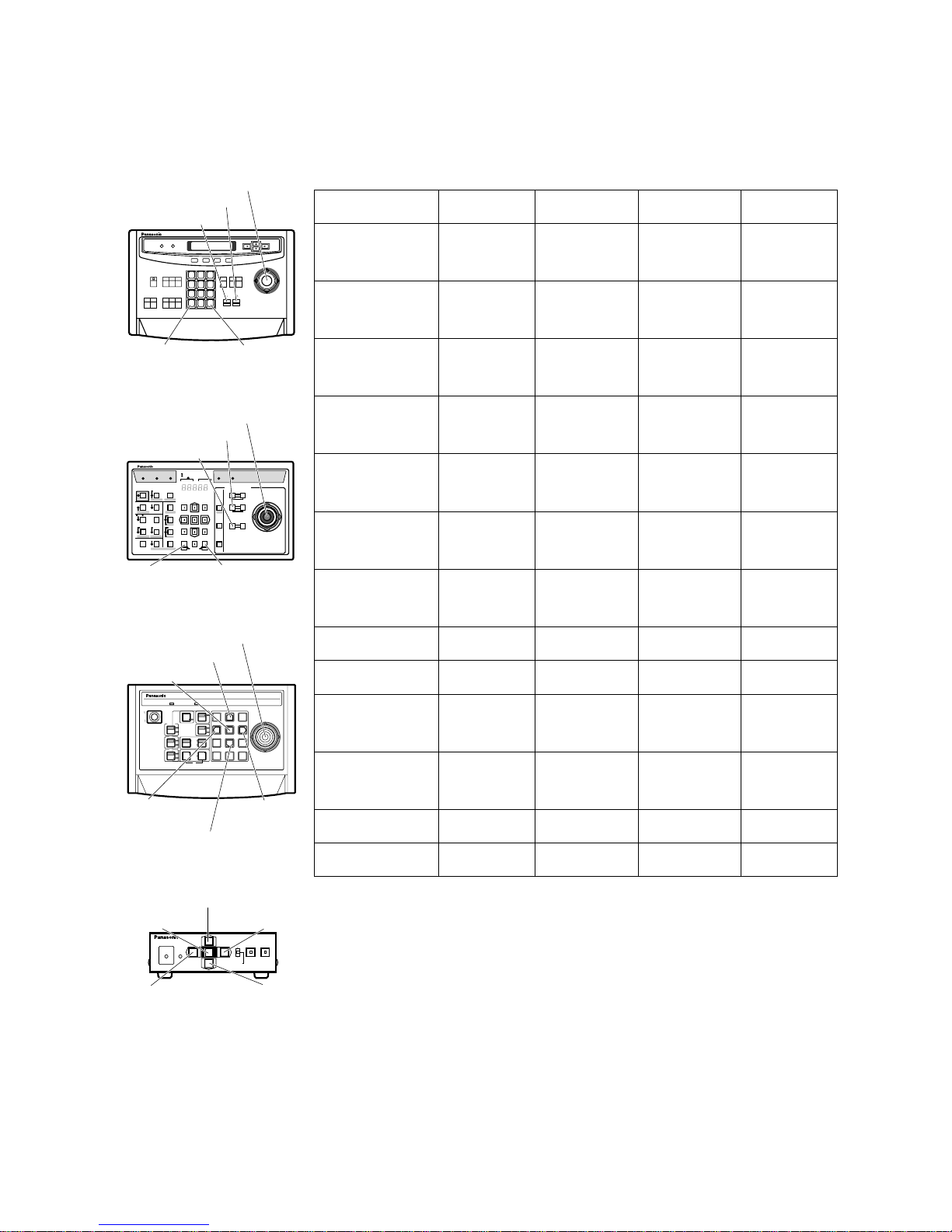
The keys (switches) to use for setup are as shown in the table below. The joystick on the connected controller may also be used for setup. The table also shows the functions versus the operations of the individual controllers. For further details, see the manual for the controller to be used. The switches and controls are abbreviated as SW and CTRL in the table.
OPERATE LOGIN ALARM
FUNCTION
SX
IRIS
CLOSE OPEN
NEAR FAR
WIDE TELE
FOCUS
ZOOM
AUTO FOCUS
IRIS RESET
HOME
SET UP
ALM RECALL
CAM SETUP
CAM FUNCTION
MULTI SCREEN
DEF
WIPER
EL-ZOOM
SHIFT
ALM RESET
VTR CAM
STILL
-1 CAM/DEC
ALM SUSPEND
+1 CAM/INC
PATROLSTOP
AUX 1
AUX 2
B/W UNIT
SEQ PAUSE
BOOST
SEQUENCE AUTO
PRESET
POSI
FS
MON
CAM
LOGOUT
ESC SET
CAMERA SITE CONTROL
UP
LR
DOWN
BUSY PROHIBITED
MONITOR
UNIT
CAMERA
System Controller
WV-CU
360
System Controller WV-CU
151151
POWER
3
6
9
2
5
8
0
1
4
7
UPUP
DOWN
L
R
SET
AF
IRIS
ZOOM
HOUSING
PAN
l
ON
BUSYPOWER
HOME POSI
NEAR FAR
FOCUS
OPEN
WIDE
CLOSE
1
PROS
CAM
MENU
ALARM
RANDOM
2
WIPER
AUTO
AUX
;
OFF
OFF
1 2 3
4 5 6
7 8 9
MON C AM
ESC SET
0
ACK
RESET
BACK
SEQ
FORWARD
SEQ ALT
DEC
–1CAM
INC
+1CAM STOP
12
AUX
CLOSE OPEN
IRIS
PRESET
FOCUS
NEAR
ZOOM
TELE
FARWIDE
System Controller WV-CU550A
LEFT RIGHT
UP
DOWN
ALARM BUSY
F3 F4F2F1
AF
[WV-CU550B]
[WV-CU151]
[WV-RM70]
Joystick
CAM (SET)
Key
MON (ESC)
Key
CAM (SET)
Key
MON (ESC)
Key
Down Switch
Right Switch
Left Switch
OPERATE
REMOTE
NORMAL PROG
ALARM
RESET
SYSTEM
ALARM OFF
Camera Controller WV-RM
707070
Up Switch
Set Switch
Right
Switch
Left Switch
Down
Switch
[WV-CU360]
Joystick
Joystick
FOCUS Switch
ZOOM Switch
FOCUS Switch
ZOOM Switch
Up Switch
Set Switch
Function/Controller WV-CU550B WV-CU360 WV-CU151 WV-RM70
Open CAM SETUP See page 14
CAM SETUP
key (for 2 seconds)
CAM MENU
SW (for 2 seconds)
See page 14
Close CAM SETUP F4 key
CAM SETUP
key (for 2 seconds)
CAM MENU
SW (for 2 seconds)
PROG SW
Move the cursor
Joystick
(←, ↑, ↓, →)
Joystick
(←, ↑, ↓, →)
Direction SW
(←, ↑, ↓, →)
Direction SW
(←, ↑, ↓, →)
Select a parameter
Joystick
(←, →)
Joystick
(←, →)
Direction SW
(←, →)
Direction SW
(←, →)
Adjust the level
Joystick
(←, →)
Joystick
(←, →)
Direction SW
(←, →)
Direction SW
(←, →)
Move the camera
direction
Joystick
(←, ↑, ↓, →)
Joystick
(←, ↑, ↓, →)
Joystick
(←, ↑, ↓, →)
Direction SW
(←, ↑, ↓, →)
Zoom & Focus
ZOOM CTRL &
FOCUS CTRL
ZOOM CTRL &
FOCUS CTRL
ZOOM SW &
FOCUS SW
Direction SW
(←, ↑, ↓, →)
Enter the setting CAM (SET) key CAM (SET) key SET SW SET SW
Open a submenu CAM (SET) key CAM (SET) key SET SW SET SW
Enter CAM ID &
PRESET ID
display position
MON (ESC) key MON (ESC) key
SET SW
(for 2 seconds)
SET SW
(for 2 seconds)
Enter MASK
setting
MON (ESC) key MON (ESC) key
SET SW
(for 2 seconds)
SET SW
(for 2 seconds)
All Reset F3 key 4+5+6 key 4+5+6 key R+SET+L SW
Open Special 2 F2 key 4+6 key 4+6 key R+L SW
Notes:
• A changed parameter is entered only when you move the cursor to
another item or open a new menu. A changed parameter will not be
entered if the setup menu is closed without taking either of the above
steps.
• Setting procedures in the following pages are described on the
assumption that the camera is used with WJ-SX850 Matrix Switcher and
WV-CU550B System Controller.

9
■ Setup Menu Description
● PRESET
(1) Position (POSITION SET)
POSITION SET adjusts the camera picture by panning, tilting, zooming and focusing.
See page 15 for the setting.
(2) Preset Identification (PRESET ID)
A preset ID (identification of up to 16 alphanumeric characters) can be displayed on the screen.
See page 16 for the setting.
(3) Light Control (ALC/MANUAL)
ALC/MANUAL refers to the mode of the incoming light level control.
See page 18 for the setting.
(4) Dwell Time (DWELL TIME)
DWELL TIME is the duration that the picture of each camera position is displayed. You can select a
preset duration from the menu.
See page 19 for the setting.
(5) Scene File (SCENE FILE)
SCENE FILE stores up to 10 files. Each file has a set of detailed parameters for Shutter Speed, AGC,
Electronic Sensitivity Enhancement, White Balance, Motion Detector and AF mode. The scene files
can be recalled later to reproduce the parameter settings under the same conditions as stored in the
files.
See page 19 for the setting.
● Home Position (HOME POSITION)
HOME POSITION is the camera’s basic position. It returns to this position automatically, when a specific
time has elapsed after a manual operation. This setting works only when AUTO MODE is OFF.
See page 20 for the setting.
● Self Return (SELF RETURN)
SELF RETURN is the time-out parameter for returning to the home position. The camera returns to AUTO
MODE if it is set to ON when a specific time has elapsed after a manual operation.
See page 20 for the setting.
● AUTO MODE
AUTO MODE is for setting the movement of the camera. You can select one from the three automatic
operation modes and one manual operation mode as follows:
OFF mode: No automatic operation. The camera can be operated only manually.
SEQ mode: The camera operates in the sequence of preset positions in numerical order.
SORT mode: The camera operates in the sequence of preset positions counterclockwise from Pan/Tilt
Starting Point.
AUTO PAN mode: The camera automatically turns within the preset panning range.
See page 21 for the setting.

10
● AUTO P AN KEY
This setting assigns SEQ, SORT, AUTO PAN or PATROL (PLAY) to the AUTO key on the controller. After
this setting, the AUTO key performs as assigned.
Note: AUTO PAN LED on the controller does not light if other than AUTO PAN is assigned.
● DIGITAL FLIP ON/OFF
Tilt range is limited within 0° to 90° if OFF is selected. If ON is selected it widens the range up to 180° with
the digital flip that reverses horizontal and vertical scanning when the camera is tilted through the 90°
point (Downright position if the camera is installed on a ceiling). Tilt range narrows from 180° to 90° if PAN
LIMIT is set to ON.
● LOCAL/REMOTE
This setting determines whether the camera continues or stops the ongoing auto operation when the
System Controller is turned off.
LOCAL: The camera continues operating in auto mode when the controller is turned OFF.
REMOTE: The camera stops operating in auto mode approx. 1 minute after the controller is turned off.
See page 23 for the setting.
● SPECIAL 1
(1) Privacy Zone ON/OFF (PRIVACY ZONE)
This setting is to mask unwanted zones, hiding them from display on the monitor. When (DIS) follows
ON or OFF, set PASSWORD LOCK to OFF if you wish to change this setting. Up to 8 zones can be
registered. Submenus are provided for zone number selection and for parameter setting. See page
23 for details.
(2) Proportional Pan-Tilt Speed ON/OFF (PROPO. P/T)
If ON is selected, the zoom ratio changes corresponding to pan-tilt speed. For example, pan-tilt
speed slows down with zoom in. See page 24 for details.
(3) Area Title ON (NESW), ON (USER), OFF
Up to 16 area titles can be added to specific scenes by DIRECTION (NESW) or alphanumerical
(USER) naming. The titles are displayed right under the camera title on the monitor when the camera
turns positions to area titles. See page 25 for details.
(4) Patrol Learn
A set of manual operations is stored (LEARN), reproduced (PLAY) or turned inactive (OFF). Patrol
operation stops if SEQ, SORT or AUTO PAN is set to AUTO MODE on the SETUP menu. See page 27
for details.
(5) Alarm IN/OUT (ALARM IN/OUT)
Alarm input and output are set on the submenu. Preset positions are assigned to ALARM IN 1 to 4. If
inputs are supplied via the ALARM INPUT connector, the camera turns to respective positions. The
camera then sends output signals via the ALARM OUT connector or the coaxial cable to the external
devices. B/W may be chosen instead of a preset position if light is so insufficient that color noise may
disturb picture clarity. CNT-CLS (Contact Closure) 1,2 and COAX ALM OUT are for alarm output setting. See page 28 for details.

11
(6) Password Lock ON/OFF (PASSWORD LOCK ON/OFF)
This setting controls access to the PRIVACY ZONE to be free or limited. If PASSWORD LOCK ON is
selected, the (DIS) follows the PRIVACY ZONE ON or OFF set on the SPECIAL1 menu.
(7) Cleaning ON/OFF
This is for refreshing the electric-mechanical contacts built in the camera. Use this function for maintenance when the camera has been directed to a specific spot or panned over a specific range for a
long time.
(8) Electric Zoom ON/OFF
Up to ten-fold ( two-fold) electrical zooming is available beside 22-fold optical zooming.
(9) Preset Alarm ON/OFF
Alarm signals are output in the following cases if ON is selected.
• Position move is completed in SEQ mode.
• Position move is completed in SORT mode.
• Position move is completed at HOME position in SELF RETURN mode.
• Position move is completed in command request.
• Position move is completed in ALARM IN.
• Position move to the start point is completed for AUTO PAN.
• Position move to the start point is completed for PATROL PLAY.
● Camera
(1) Camera Identification (CAMERA ID)
You can use the camera identification (CAMERA ID) to assign a name to the camera. The camera ID
consists of up to 16 alphanumeric characters. You can select whether to have the camera ID displayed on the monitor screen or not.
See page 32 for the setting.
(2) Light Control (ALC/MANUAL)
You can select the mode for adjusting the lens iris.
The modes are as follows:
ALC: The lens iris is automatically adjusted according to the brightness of the object.
You can select one of two modes (SUPER-D2 ON or SUPER-D2 OFF).
MANUAL: The lens iris is fixed at the value you have set regardless of the brightness of the object.
• ALC Mode with SUPER-D2 ON
Super Dynamic 2 Function (SUPER-D2)
The important object in a scene is usually placed in the center of the monitor’s screen. In SUPER-D2
mode, more photometric weight is given to the center of the screen (where the important object is
located) than to the edge of the picture (where a bright backlight would most likely be located).
You can use the SUPER-D2 function if you select ALC. It eliminates interference by strong background lighting which makes the camera picture dark, such as a spotlight.
See page 33 for the setting.
• ALC Mode with SUPER-D2 OFF
In this mode, the picture is divided into 48 areas. If there is a source of brightness that interferes with
the clarity of the picture in these masks, corresponding areas mask the light to keep the clarity of the
picture.

12
Generally, when a light from the background is too strong such as a spotlight, all objects except the
main object in the picture are displayed darker because the lens iris is adjusted with respect to
strong brightness. This model ignores strong brightness by masking the source of the strong brightness, thereby main object is displayed clearly.
Note: The result of field setup of the mask area and level adjustment is fed back (effected) to the lens
iris control in ALC mode.
(3) Shutter Speed (SHUTTER)
You can select the shutter speed from 1/60 (OFF), 1/100, 1/250, 1/500, 1/1 000, 1/2 000, 1/4 000, and
1/10 000 seconds.
See page 35 for the setting.
(4) Gain Control (AGC)
You can set the gain (brightness level portion of an image) to automatic adjustment (Automatic Gain
Control ON) or fixed (Automatic Gain Control OFF).
See page 35 for the setting.
(5) Electronic Sensitivity Enhancement (SENS UP)
The electronic sensitivity enhancement (SENS UP) function varies the shutter speed to raise the sensitivity in low light conditions when OFF is selected for ALC.
You can select the shutter speed for SENS UP from the preset values as follows;
1/30 seconds (x2), 1/15 seconds (x4), 1/10 seconds (x6), 1/6 seconds (x10), 1/3.8 seconds (x16), or
1/1.9 seconds (x32). See page 35 for the setting.
There are two modes for SENS UP as follows;
AUTO: If you select x32, for example, the sensitivity is raised automatically to x32 max.
FIX: If you select x32, for example, the sensitivity is raised to just x32.
Notes:
• Moving objects will appear blurred when shot during the electronic sensitivity enhancement
mode since SENS UP is equivalent to setting the shutter speed to a slower speed in a still picture
camera.
• The horizontal and vertical resolution will be lowered in this mode.
• If the video output level is adjusted too low (the iris opening is too small), the Electronic
Sensitivity Enhancement (SENS UP)/AUTO mode will not function.
(6) Synchronization (SYNC)
You can select internal sync mode (INT) or line-lock sync (LL). Additionally, this model accepts the
VD2 signal (multiplexed vertical drive signal with the composite video output signal) from a specified
component. Whenever the VD2 signal is supplied to this camera, the camera automatically switches
to the VD2 sync mode.
When you select line-lock sync (LL) you can set vertical phase adjustment.
See page 36 for the setting.
Important Notice:
The priority of sync modes is as follows:
1. Multiplexed Vertical Drive (VD2) (Highest)
2. Line-lock (LL)
3. Internal Sync (INT) (Lowest)
Note: The priority of automatic sync mode is the same as shown above.

13
(7) White Balance (WHITE BAL)
You can select one of two modes for white balance adjustment as follows:
• ATW (Auto Tracing White Balance)
In this mode, the color temperature is monitored continuously and thereby white balance is set
automatically. The color temperature range for the proper white balance is approximately 2 600 6 000K. Proper white balance may not be obtained under the following conditions:
1. The color temperature is out of the 2 600 - 6 000K range.
2. When the scene contains mostly high color temperature (bluish) objects, such as a blue sky.
3. When the scene is dim.
In these cases, select the AWC mode.
• AWC (Automatic White Balance)
In this mode, accurate white balance is obtained within a color temperature range of approx. 2 300 10 000K.
See page 38 for the setting.
(8) Motion Detector (MOTION DET)
The Motion Detector detects the motion in the scene by monitoring changes in the brightness level.
You can select the level of sensitivity for motion on the SET UP menu.
When the camera detects the motion it supplies the alarm signal to the external equipment and stops
at its position for the preset DWELL time.
See page 39 for the setting.
(9) Auto Focus (AF MODE)
The camera adjusts the focus automatically to the best position by sensing sharpness in the center
area of the picture. S, M and L stand for the breadth of the sensing area: Small, Middle and Large.
See page 40 for details.
MANUAL S, M, L: Auto-focus is activated when the AF key on the controller is pressed.
AUTO S, M, L: Auto-focus is activated after a manual operation: pan, tilt or zoom.
Note: If SENS UP is set to ON, AUTO (S/M/L) is disabled and MANUAL (S/M/L) is automatically
selected.
(10)Special 2 Menu (SPECIAL 2) or Special Menu (SPECIAL)
This menu allows you to adjust the following items: chroma level, aperture level, pedestal level, chroma phase (hue), and up side down. You can also reset your parameters to the values preset at the
factory.
See page 41 for the setting.
● RS485 communication
Communication parameters
• Full/Half duplex (page 49)
• Transmission speed (2 400 - 19 200 bps) (page 43)
• Parity bit, Stop bit, Flow control (page 43)
• Retransmit time, Delay time, Alarm output (page 44)
• Camera units (96 units max.) (page 45)
• Termination ON/OFF (page 45)
• Reset parameters (page 45)
14
SETTING PROCEDURES
The following setting procedures are described on the assumption that this model is used in combination
with the WJ-SX550B matrix switcher and WV-CU550B system controller. In case of using other controller
than the WV-CU550B, refer to the table on page 8.
■ Menu Display
● Setup Menu Display
WV-CU550B
1. Select the number of the camera you want to set up and a monitor
to display the SET UP MENU.
2. Display the D4 menu on the LCD by pressing the appropriate cursor buttons.
3. Press the F1 button.
The SET UP MENU appears on the monitor.
4. To close the SET UP MENU, press the F4 button.
WV-CU360
Press the CAM SETUP key for 2 seconds or more to open the
SETUP menu.
WV-CU151
Press the CAM MENU switch for 2 seconds or more to open the
SETUP menu.
WV-RM70
1. Turn the MODE SELECTION switch to the NORMAL or ALARM
OFF position.
2. Press the PROG switch for 2 seconds or more to open the
Program menu.
3. Move the cursor to Camera Set Up, then press the SET switch to
open the SETUP menu.
D4 menu
F1
F1 F2 F3 F4
Camera Set Up Menu
Res A.Res Exit
F2 F3 F4
Camera Set Up Menu
On Exit
** RS485 SET UP **
UNIT NUMBER
SUB ADDRESS
BAUD RATE
DATA BIT
PARITY CHECK
STOP BIT
XON/XOFF
WAIT TIME
ALARM DATA
DELAY TIME
RET
1
1
19200
8
NONE
1
NOT USE
OFF
AUTO2
OFF
Submenu
(for RS485 setup)
*** SET UP MENU ***
PRESET 1*
MAP
HOME POSITION
SELF RETURN
AUTO MODE
AUTO PAN KEY
DIGITAL FLIP
LOCAL/REMOTE
SPECIAL1
CAMERA
RS485 SET UP
15
10MIN
OFF
AUTO PAN
OFF
LOCAL
Setup menu
*** SET UP MENU ***
PRESET 1*
MAP
HOME POSITION
SELF RETURN
AUTO MODE
AUTO PAN KEY
LOCAL/REMOTE
PATROL
CLEANING
CAMERA
8
10MIN
OFF
AUTO PAN
LOCAL
STOP
OFF
Setup menu
● Submenu Display
The items marked can be selected/changed on the submenu.
• Move the cursor to an item with the mark and press the CAM
(SET) key. The submenu is displayed.
15
■ Preset
● Preset Menu Display
1. Displaying the preset menu directly
(1) Move the cursor to PRESET 1 and move the joystick to the left
or right to select the position number to be set.
(2) Press the CAM (SET) key.
The preset setting menu appears on the monitor screen.
2. Displaying the preset menu from the PRESET NUMBER SET menu
(1) Move the cursor to MAP and press the CAM (SET) key.
The PRESET NUMBER SET menu appears on the monitor
screen.
(2) Move the cursor to the position number to be set and press
the CAM (SET) key.
The preset setting menu appears on the monitor screen. To
display position number 33-64, move the cursor to “33-64” in
the lower left of the screen and press the CAM (SET) key.
Notes:
• The *mark means the position number is preset.
• The character H means home position.
• On the second bottom line the preset ID is displayed respective to the selected number. “DOOR” after “ID:” is for preset
position numbers 1 in the example shown above.
• Preset numbers 1 through 4 are linked to alarm inputs 1
through 4. If alarm input 1 comes in, the camera turns to preset position 1, or to other positions according to alarm input 2,
3 or 4.
• The PRESET NUMBER SET menu indicates the 8 preset positions (1 - 8) for the WV-CS554 combination camera.
*** SET UP MENU ***
PRESET 1*
MAP
HOME POSITION
SELF RETURN
AUTO MODE
AUTO PAN KEY
DIGITAL FLIP
LOCAL/REMOTE
SPECIAL1
CAMERA
RS485 SET UP
15
10MIN
OFF
AUTO PAN
OFF
LOCAL
Setup menu
** PRESET NUMBER SET **
2
6
10
14
18
22
26
30
1*
5
9
13
17
21
25
29
ID:DOOR
33-64 RET
3
7
11
15
19
23
27
31
4
8
12
16
20
24
28
32
PRESET NUMBER SET menu
(1-32)
** PRESET NUMBER SET **
34
38
42
46
50
54
58
62
33
37
41
45
49
53
57
61
ID:
1-32 RET
35
39
43
47
51
55
59
63
36
40
44
48
52
56
60
64
PRESET NUMBER SET menu
(33-64)
● Position Setting
1. Move the cursor to POSITION SET on the preset setting menu and
press the CAM (SET) key.
The position setting menu is displayed.
2. To set panning/tilting positions
(1) Move the cursor to PUSH SET next to PAN/TILT and press the
CAM (SET) key. The PAN/TILT setting menu appears.
(2) Select panning/tilting positions by moving the joystick up and
down, right and left, and press the CAM (SET) key.
The positions are set and the screen returns to the position
setting menu.
PRESET NO. 1*
POSITION SET
PRESET ID
ALC/MANUAL
DWELL TIME
SCENE FILE
PRESET SPEED
RET DEL
ON
ALC
10S
OFF
••••|••••
L H
Preset setting menu
→
PUSH SET
→
PUSH SET
** POSITION 1 **
PAN/TILT
ZOOM/FOCUS
PAN OFFSET SET
← −
10.0
→
RET
FLOOR1
DOOR
Position setting menu
→
PUSH SET
→
PUSH SET
** POSITION 1 **
PAN/TILT
ZOOM/FOCUS
U TILT D/L PAN R
RET
FLOOR1
DOOR
*** SET UP MENU ***
PRESET 1*
MAP
HOME POSITION
SELF RETURN
AUTO MODE
AUTO PAN KEY
DIGITAL FLIP
LOCAL/REMOTE
SPECIAL1
CAMERA
RS485 SET UP
15
10MIN
OFF
AUTO PAN
OFF
LOCAL
Setup menu
PAN/TILT setting menu
16
3. Pan Offset
If the camera is replaced with a new one, Pan Offset is used to
adjust its positions to be the same as before.
Preset position data is uploaded by the controller that was once
downloaded before the former camera was removed.
Caution: The preset data for conventional protocol (WV-CS650
for example) is incompatible with WV-CS854’s. WV-CS854’s
preset data will be destroyed if you upload the conventional
data. When this happened, prepare a WV-CS854 having the
initial factory settings. Download the factory settings into the
controller and then upload to the camera whose data is
destroyed.
(1) Display the PRESET NUMBER SET menu.
(2) Select a position number for the picture to be most enlarged
among the numbers by moving the joystick. Then press the
CAM(SET) key. POSITION setting menu appears.
(3) Move the cursor to PAN OFFSET SET and select the left or
right arrow by moving the joystick.
(4) Press the CAM (SET) key until the desired offset value in
degree appears.
(5) Move the cursor to other than PAN OFFSET, then press the
MON (ESC) key.
Notes:
• Further adjustment of the other positions is unnecessary. This
adjustment applies to all other positions.
• Make sure to move the cursor before pressing the key in step
5. Otherwise the settings will be ignored.
• Retry when the camera fails to upload or download the data.
4. To set the lens zoom and focus positions
(1) Move the cursor to PUSH SET next to ZOOM/FOCUS and
press the CAM (SET) key. The ZOOM/FOCUS setting menu
appears.
(2) Select a zoom position by moving the zoom control up and
down, and a focus position by moving the focus control up
and down, and then press the CAM (SET) key.
The positions are set and the screen returns to the position
setting menu.
Note:
When the camera is used at a nearly horizontal angle, the
focus may not be adjustable to a high level of accuracy.
5. Move the cursor to RET and press the CAM (SET) key to return to
the preset setting menu.
→
PUSH SET
→
PUSH SET
** POSITION 1 **
PAN/TILT
ZOOM/FOCUS
PAN OFFSET SET
← −
10.0
→
RET
FLOOR1
DOOR
Position setting menu
→
PUSH SET
→
PUSH SET
** POSITION 1 **
PAN/TILT
ZOOM/FOCUS
U ZOOM D/L FOCUS R
RET
FLOOR1
DOOR
● Preset ID Setting
1. Move the cursor to PRESET ID on the preset setting menu and
select ON or OFF by moving the joystick to the left or right.
ON: Preset ID is displayed on the screen.
OFF: Preset ID is not displayed.
PRESET NO. 1*
POSITION SET
PRESET ID
ALC/MANUAL
DWELL TIME
SCENE FILE
PRESET SPEED
RET DEL
ON
ALC
10S
OFF
••••|••••
L H
Preset setting menu
→
PUSH SET
→
PUSH SET
** POSITION 1 **
PAN/TILT
ZOOM/FOCUS
PAN OFFSET SET
← −
10.0
→
RET
FLOOR1
DOOR
Position setting menu
** PRESET NUMBER SET **
2
6
10
14
18
22
26
30
1*
5
9
13
17
21
25
29
ID:DOOR
33-64 RET
3
7
11
15
19
23
27
31
4
8
12
16
20
24
28
32
PRESET NUMBER SET menu
(1-32)
→
PUSH SET
→
PUSH SET
** POSITION 1 **
PAN/TILT
ZOOM/FOCUS
PAN OFFSET SET
← −
10.0
→
RET
FLOOR1
DOOR
Position setting menu
ZOOM/FOCUS setting menu
17
2. Press the CAM (SET) key to display the preset ID setting menu.
To enter a new PRESET ID
1. Move the cursor to the desired character using the joystick,
and press the CAM (SET) key.
2. The selected character appears in the editing area. (The
pointer in the editing area moves to the right automatically at
this moment.) To enter a blank, select SPACE.
3. Repeat the above procedure until all characters are entered.
Command
Editing
Area
Character
Area
Pointer
Character Cursor
PRESET NO. 1*
0123456789
ABCDEFGHIJKLM
NOPQRSTUVWXYZ
().,'":;&#!?=
+-*/%$
SPACE
COPY POSI RET RESET
DOOR............
Preset ID setting menu
To copy a preset ID from another position
1. Move the cursor to COPY and press the CAM (SET) key. The
preset ID in the immediately preceding position is shown.
Each consecutive pressing of the CAM (SET) key displays the
ID preceding the one currently displayed.
2. Display the most prospective ID.
3. Follow the step “To change an entered PRESET ID” if necessary.
To change an entered PRESET ID
1. Move the pointer to the character to be edited in the editing
area by using the joystick, and press the CAM (SET) key.
2. Select a new character by using the joystick.
3. Press the CAM (SET) key to determine the PRESET ID.
PRESET NO. 1*
0123456789
ABCDEFGHIJKLM
NOPQRSTUVWXYZ
().,'":;&#!?=
+-*/%$
SPACE
COPY POSI RET RESET
DOOR............
PRESET NO. 1*
0123456789
ABCDEFGHIJKLM
NOPQRSTUVWXYZ
().,'":;&#!?=
+-*/%$
SPACE
COPY POSI RET RESET
DOOR............
To delete an entered PRESET ID
Move the cursor to RESET and press the CAM (SET) key.
PRESET NO. 1*
0123456789
ABCDEFGHIJKLM
NOPQRSTUVWXYZ
().,'":;&#!?=
+-*/%$
SPACE
COPY POSI RET RESET
DOOR............
18
To set a display position for a PRESET ID
1. Move the cursor to POSI and press the CAM (SET) key. The
display position set menu appears.
2. Using the joystick, move the ID to the desired position on the
screen, then press the MON (ESC) key. The display position
is set and the screen returns to the PRESET ID setting menu.
PRESET NO. 1*
0123456789
ABCDEFGHIJKLM
NOPQRSTUVWXYZ
().,'":;&#!?=
+-*/%$
SPACE
COPY POSI RET RESET
DOOR............
FLOOR 1
DOOR
PRESET NO. 1*
0123456789
ABCDEFGHIJKLM
NOPQRSTUVWXYZ
().,'":;&#!?=
+-*/%$
SPACE
COPY POSI RET RESET
DOOR............
Display position set menu
To enter the next ID without returning to the preset setting
menu
1. With the preset ID setting menu, move the cursor to the top
line and select the desired position number by moving the
joystick to the left or right.
2. Enter, copy, change or delete the ID as described above.
To return to the preset setting menu
Move the cursor to RET and press the CAM (SET) key.
● Light Control Setting
1. Move the cursor to ALC/MANUAL and select ALC or MANUAL by
moving the joystick to the left or right.
ALC: The lens iris is automatically adjusted to suit the brightness
of the object.
MANUAL: The lens iris is fixed at the set value regardless of the
brightness of the object.
2. In case of ALC
Press the CAM (SET) key. The back light compensation menu
appears in the display. See page 33 for the setting.
3. In case of MANUAL
Press the CAM (SET) key. The setting menu appears in the display. Set the lens iris level as desired by moving the joystick to the
left or right.
PRESET NO. 1*
POSITION SET
PRESET ID
ALC/MANUAL
DWELL TIME
SCENE FILE
PRESET SPEED
RET DEL
ON
ALC
10S
OFF
••••|••••
L H
Preset setting menu
** MANUAL CONT **
IRIS
RET
••••|••••
CLOSE OPEN
Manual setting menu
 Loading...