

Panasonic WV-CS650 User Manual

Combination Camera
WV-CS650
WV-CS654
WV-CSR650
ENGLISHDEUTSCHFRANÇAISESPAÑOL
Before attempting to connect or operate this product, please read these instructions completely

ENGLISH VERSION
We declare under our sole responsibility that the product to
which this declaration relates is in conformity with the
standards or other normative documents following the
provisions of Directives EEC/73/23 and EEC/89/336.
Noi dichiariamo sotto nostra esclusiva responsabilità che il
prodotto a cui si riferisce la presente dichiarazione risulta
conforme ai seguenti standard o altri documenti normativi
conformi alle disposizioni delle direttive CEE/73/23 e
CEE/89/336.
Wij verklaren als enige aansprakelijke, dat het product
waarop deze verklaring betrekking heeft, voldoet aan de
volgende normen of andere normatiefve dokumenten,
overeenkomstig de bepalingen van Richtlijnen 73/23/EEC en
89/336/EEC.
CAUTION
RISK OF ELECTRIC SHOCK
DO NOT OPEN
CAUTION:
TO REDUCE THE RISK OF ELECTRIC SHOCK,
DO NOT REMOVE COVER (OR BACK), NO
USER SERVICEABLE PARTS INSIDE.
REFER SERVICING TO QUALIFIED SERVICE
PERSONNEL.
The lightning flash with arrowhead
symbol, within an equilateral triangle, is
interned to alert the user to the
presence of uninsulated "dangerous
voltage" within the product's enclosure
that may be of sufficient magnitude to
constitute a risk of electric shock to
persons.
The exclamation point within an
equilateral triangle is intended to alert
the user to the presence of important
operating and maintenance (servicing)
instructions in the literature
accompanying the appliance.
Vi erklærer os eneansvarlige for, at dette produkt, som
denne deklaration omhandler, er i overensstemmelse med
den følgende standarder eller andre normative dokumenter i
følge bestemmelserne i direktivene 73/23/EEC og
89/336/EEC.
Vi deklarerar härmed värt fulla ansvar för att den produkt till
vilken denna deklaration hänvisar är i överensstämmelse
med standarddokument, eller andra normativa dokument
som framstölls i Direktiv 73/23/EEC och 89/336/EEC.
Ilmoitamme yksinomaisella vastuullamme, että tuote, jota
tämä ilmoitus koskee, noudattaa seuraavia standardeja tai
muita ohjeellisia asiakirjoja, jotka noudattavat direktiivien
73/23/EEC ia 89/336/EEC. säädöksiä.
Vi erklærer oss alene ansvarlige for at produktet som denne
erklæringen gjelder for, er i overensstemmelse med følgende
normer eller andre normgivende dokumenter som fælger
bestemmelsene i direktiven 73/23/EEC og 89/336/EEC.
For U.K.
FOR YOUR SAFETY PLEASE READ THE FOLLOWING TEXT
CAREFULLY.
WARNING
THIS APPARATUS MUST BE EARTHED
The wires in this mains lead are coloured in accordance with the
following code.
As the colours of the wire in the mains lead of this appliance may
not correspond with the coloured markings identifying the terminals in
your plug, proceed as follows.
The wire which is coloured green-and-yellow must be connected
to the terminal in the plug which is marked with the letter E or by the
earth symbol
The wire which is coloured blue must be connected to the terminal
in the plug which is marked with the letter N or coloured black.
The wire which is coloured brown must be connected to the
terminal in the plug which is marked with the letter L or coloured red.
Green-and-yellow: Earth
Blue: Neutral
Brown: Live
I or coloured green or green-and-yellow.
IMPORTANT
The serial number of this product may be found on the
top of the unit.
You should note the serial number of this unit in the
space provided and retain this book as a permanent
record of your purchase to aid identification in the event
of theft.
Model No.
Serial No.
WARNING:
TO PREVENT FIRE OR ELECTRIC SHOCK HAZARD, DO NOT EXPOSE THIS APPLIANCE TO RAIN OR
MOIS
TURE.

IMPORTANT! / WICHTIG! / IMPORTANT!
■ Do not install the camera near the air
outlet of an air conditioner.
The lens may become cloudy due to condensation if the camera is used under the following
conditions.
• Rapid temperature fluctuations when switching the air conditioner on or off.
• Rapid temperature fluctuations when opening or closing doors.
• Use in an environment where eyeglasses fog
up.
• Use in a room where the air is filled with cigarette smoke or other impurities.
If the lens becomes cloudy due to condensation, remove the dome cover and dry all
moist surfaces with a soft cloth.
■ Die Kamera darf nicht in der Nähe
des Luftaustritts einer Klimaanlage
installiert werden.
Unter folgenden Umstäanden kann Kondensation zum Beschlagen des Objektivs führen:
• Starke Temperaturschwankungen beim Ein-
und Ausschalten der Klimaanlage.
• Starke Temperaturschwankungen beim Öffnen und Schließen von Türen.
• Betrieb in einem Raum, in dem Brillengläser
beschlagen.
• Starker Zigarettenrauch oder anderweitig
verunreinigte Raumluft.
IBei Beschlagen des Objektivs die Glocke
abnehmen und alle beschlagenen Flächen
mit einem weichen Tuch trockenwischen.
■ La caméra vidéo ne doit pas être
installée près d’une prise de refoulement d’air d’un climatiseur.
En effet, la surface de l’objectif risque d’être
embuée à la suite d’une formation de condensation de l’humidité si la caméra vidéo est utilisée
dans les conditions suivantes.
• Variations rapides de température lorsque le
climatiseur est mis en fonction et qu’il est arrêté.
• Variations rapides de température lorsque
les portes sont ouvertes et fermées.
• Utilisée dans des conditions telles que des
lunettes sont rapidement embuées.
• Utilisée dans une pièce dont l’air est saturé
de fumée de cigarette ou toute autre sorte
d’impuretés.
Si toutefois la surface de l’objectif est
embuée à la suite de la formation d’une condensation de l’humidité, retirer le couvercle
du dôme et assécher toutes les surfaces
atteintes par l’humidité avec un morceau
d’étoffe souple.
■ Removal of Dome Cover
1. Remove the 2 dome clamp screws
(small) and 2 dome retainers using a precision screwdriver.
Be careful not to lose these parts
because they will be used again.
2. Remove the dome cover by turning it
counterclockwise.
3. Dry all moist surfaces with a soft cloth.
4. Place the dome cover back on, and fasten it securely with the screws and dome
retainers.
■ Entfernen der Glocke
1. Mit einem Präzisionsschraubenzieher die
2 Klemmschrauben (klein) mit Haltern
aus der Glocke entfernen und sorgfältig
aufbewahren.
2. Die Glocke entgegen dem Uhrzeigersinn
drehen und abnehmen.
3. Alle beschlagenen Flächen mit einem
weichen Tuch trockenwischen.
4. Die Glocke wieder aufsetzen und mit den
Schrauben und Haltern befestigen.doors.
■ Comment retirer le couvercle du
dôme
1. Retirer les deux vis d’immobilisation du
couvercle du dôme (petites) et les deux
éléments de retenue en se servant d’un
tournevis de précision.
Veiller à ne pas égarer ces pièces parce
qu’elles seront utilisées ultérieurement.
2. Retirer le couvercle du dôme en le
faisant pivoter dans le sens inverse des
aiguilles d’une montre.
3. Assécher toutes les surfaces atteintes
par l’humidité avec un morceau d’étoffe
souple.
4. Remonter le couvercle du dôme et bloquer fermement les vis de fixation et les
éléments de retenue du dôme.

CONTENTS
PREFACE .......................................................... 1
FEATURES ........................................................ 1
PRECAUTIONS ................................................. 2
CONSTRUCTION .............................................. 3
SETUP ............................................................... 4
■ Setup Menu ............................................... 4
■ Setup Menu Description ........................... 6
SETTING PROCEDURES ................................ 10
■ Menu Display .......................................... 10
■ RS485 Set Up ......................................... 10
■ Preset ..................................................... 12
■ Deleting Preset Positions ........................ 17
■ Home Position Setting ............................. 17
PREFACE
Panasonic presents highly advanced CCTV
technology meets the demand of new and everchanging applications. This model is utilized
video surveillance device that incorporates a
Digital Signal Processing (DSP) highperformance camera, pan/tilt mechanism, 10
times zoom lens and receiver in its compact
enclosure.
The camera portion incorporating a high-
■ Self Return Setting .................................. 17
■ Auto Mode Setting .................................. 18
■ FLIP-A-CHIP Setting ............................... 19
■ LOCAL/REMOTE Setting ........................ 19
■ Camera Setting ....................................... 20
INSTALLATION ............................................... 31
CONNECTIONS .............................................. 34
SYSTEM CONNECTIONS ............................... 36
PREVENTION OF BLOOMING
AND SMEAR ................................................... 37
SPECIFICATIONS ........................................... 37
ACCESSORIES ............................................... 38
OPTIONAL ACCESSORIES ............................ 38
sensitivity CCD provides 480-line horizontal
resolution. With its advanced digital signal
processing circuit, it is equipped to handle the
surveillance tasks of the coming age.
The pan/tilt portion, allowing 360-degree endless
panning, is designed to meet specific user need.
This model utilized surveillance device offers
cutting-edge technology for advanced video
surveillance.
ENGLISH
FEATURES
1. The following functions are built in.
(1) The SUPER-D function eliminates inter-
ference by strong background lighting
which makes the camera picture dark,
such as a spotlight.
(2) Dynamic range of 42 dB
(3) Auto/Manual White Balance Function
(4) Electronic Shutter Function
(5) Auto Light Control (ALC)/Manual Over-
ride Iris
2. Minimum illumination of 3 lux (0.3 footcandle)
3. High quality picture:
(a) 2H type vertical enhancer for greater
picture sharpness
(b) Chroma averaging circuit for better
colour signal to noise ratio
(c) Minimum of aliasing on fine objects
(d) Highlight aperture correction for greater
picture detail of bright objects
4. Back Light Compensation for use under
unusual lighting conditions.
5. Selectable electronic sensitivity enhancing
modes including : AUTO, MANUAL and OFF
6. Built in Digital Motion Detector
7. 64 preset position-Position, focus, zoom
ratio, rotation mode, etc.
8. 360-degree endless panning.
9. Maximum 240 degrees/second speed from
one position to the next.
10. There is no distance limit for remote access
with the specified extension unit. (only for
WV-CSR650)
- 1 -

PRECAUTIONS
1. Do not attempt to disassemble the
camera.
To prevent electric shock, do not remove
screws or covers.
There are no user serviceable parts inside.
Ask a qualified service person for servicing.
2. Handle the camera with care.
Do not abuse the camera. Avoid striking,
shaking, etc. The camera could be
damaged by improper handling or storage.
3. Do not expose the camera to rain or
moisture, or try to operate it in wet areas.
This product is designed for indoor use or
locations where it is protected from rain and
moisture.
Turn the power off immediately and ask a
qualified service person for servicing.
Moisture can damage the camera and also
create the danger of electric shock.
4. Do not use strong or abrasive detergents
when cleaning the camera body.
Use a dry cloth to clean the camera when
dirty.
In case the dirt is hard to remove, use a mild
detergent and wipe gently.
8. If “OVER HEAT” sign appears on the
monitor screen
The temperature inside the camera exceeds
the normal level because of a malfunction of
the cooling fan etc. Turn the power off
immediately and refer servicing to qualified
service personal.
9. Do not operate the camera beyond the
specified temperature, humidity or power
source ratings.
Use the camera under conditions where
temperature is between −10°C - +50°C (14°F
- 122°F), and humidity is below 90 %. The
input power source is 220 -240 V AC 50Hz
for WV-CS650, WV-CSR650, and 24 V AC
50Hz for WV-CS654.
CAUTION
To prevent fire or electric shock hazard, the
UL listed wire, VW-1, style 1015, AWG 18 or
UL listed power supply cord, type SJT should
be used for the cable for 24V AC input
terminals.
5. Never face the camera towards the sun.
Do not aim the camera at bright objects.
Whether the camera is in use or not, never
aim it at the sun or other extremely bright
objects. Otherwise, blooming or smear may
be caused.
6. Do not install this camera upside down
This camera is designed for mounting on the
ceiling or wall. Using this camera installed
upside down, for example,mounted on the
floor, may cause malfunction.
7. Do not block cooling holes on the diecast
case
This camera has a cooling fan inside.
Blocking the cooling holes leads to build up
of heat the camera and may cause
malfunction.
- 2 -
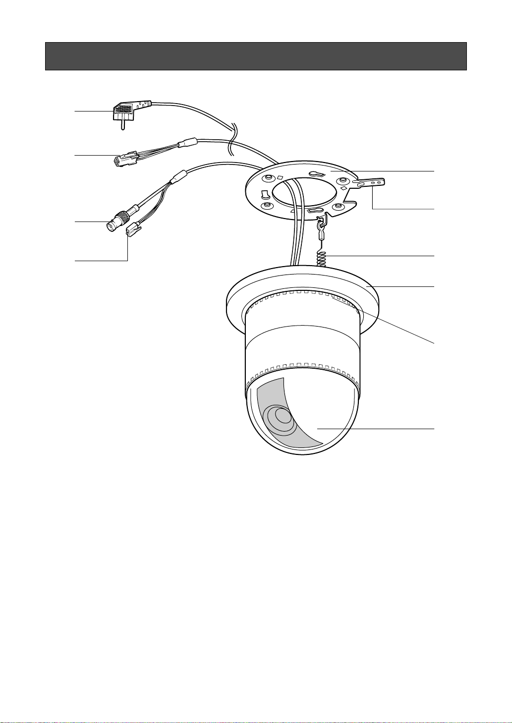
CONSTRUCTION
e
*
e
w
r
t
q
(1) Data Cable (only for WV-CSR650)
(2) Video Output Connector
y
u
i
o
(6) Fall Prevention Wire
(7) Decoration Cover
(3) Power Cable for WV-CS650 and WV-
CSR650
(3*) Power Cable for WV-CS654
(4) Camera Mounting Angle
(5) Panning Start Point
(8) Cooling Holes
(9) Dome Cover
- 3 -
Dwell Time
Setting
Scene File
Setting
Camera ID
Display
Position
Preset ID
Display
Position
Super-D
ON
Shutter
Speed
ON/OFF
AGC
ON/OFF
Preset
Setting
Menu
Position
No.
Selection
MAP
Menu
Camera
ID
Editing
Electronic
Sensitivity
Up ON/OFF
White
Balance
AWC
ATW
Super-D
OFF
Light
Control
Motion
Detector
ON/OFF
ALC
MANUAL
Super-D
ON
AF Mode
MANUAL/
AUTO
Manual
Level
Adjustment
(Contrast)
Manual
Mask Area
Selection
Manual
Level
Adjustment
Manual
Level
Adjustment
Sensitivity
Level
Adjustment
Manual
Mask
Area
Selection
Mask
Area
Selection
AF
Area
Selection
Manual
Mask
Area
Selection
Home
Position
Setting
Self
Return
Setting
Auto-pan
Setting
Menu
Auto
Mode
Setting
Flip-A-
Chip
ON/OFF
CAMERA
SET UP MENU
Manual
Iris
Adjustment
Super-D
OFF
Preset
Menu
Position
Setting
Preset ID
Editing
Setup
Menu
Light
Control
ALC
MANUAL
SETUP
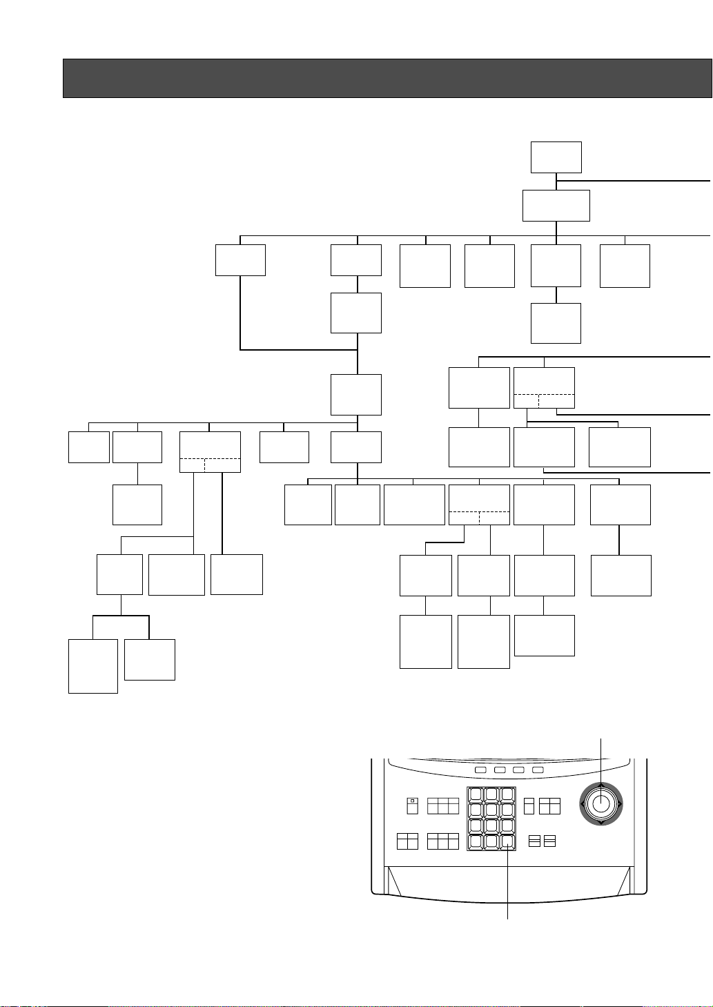
■ Setup Menu
This camera utilizes a user setup menu that is displayed on-screen.
This setup menu contains various sub menus that form a tree-type
structure as shown below.
This menu is described in the "SETUP MENU DESCRIPTION".
The above menus should be set with the
following switches.
• WV-CU550A
Joystick: Used to move the Cursor
Upward/Downward/Right/
CAM (SET) Key: This key is for setting the
Left and select the mode.
Also used to adjust the level.
mode and switching between
menus.
- 4 -
ACK
BACK
RESET
SEQ
DEC
AUX
-1CAM
FORWARD
SEQ ALT
INC
+1CAM
STOP12
1 2 3
4 5 6
7 8 9
MON CAM
ESC SET
F3 F4F2F1
PRESET
AF
ZOOM
TELE
0
WIDE
CAM (SET) Key
Joystick
IRIS
CLOSE
OPEN
LEFT
FOCUS
NEAR
FAR
System Controller WV-CU 550A
DOWN
UP
RIGHT

Note:
The menus described in bold are displayed only when WV-CSR650 is used.
UNIT
NUMBER
Local/
Remote
Shutter
Speed
ON/OFF
Manual
Iris
Adjustment
Manual
Level
Adjustment
(Contrast)
TRANSMISSION
SPEED
AGC
ON/OFF
INT
Manual
Selection
Manual
Mask Area
Selection
DATA
Camera
Menu
Sensitivity
Up
ON/OFF
LL
Manual
Selection
V-phase
Manual
Adjustment
BIT
PARITY
BIT
Sync.
INT/LL
VD2
Automatic
Selection
STOP
BIT
Manual
Level
Adjustment
Manual
Mask
Area
Selection
XON/
XOFF
White
Balance
AWC
Manual
Level
Adjustment
Manual
Mask
Area
Selection
ATW
WAIT
TIME
Motion
Detector
ON/OFF
Sensitivity
Level
Adjustment
Mask
Area
Selection
AF Mode
Manual/
Auto
ALARM
DATA
Special
Menu
DELAY
TIME
Up
Side
Down
• WV-RM70
(available with all models except WV-CSR650)
Up Switch: Moves the cursor upwards.
Down Switch: Moves the cursor downwards.
Right Switch: Moves the cursor right. This
switch also selects the mode
and can be used to adjust
certain Levels.
Left Switch: Moves the cursor left. This
switch also selects the mode
AF
Area
Selection
Gain
AP GainChroma
Pedestal
Camera
Reset
and can be used to adjust
certain Levels.
Set Switch: This switch is for setting the
mode and switching between
menus.
Left Switch
Set Switch
- 5 -
Up Switch
Right Switch
Down Switch

■ Setup Menu Description
● RS485 site communication (only WV-CSR650)
Communication parameters
• Full/Half duplex (page 31)
• Transmission speed (2 400 - 19 200 bps) (page 11)
• Parity bit, Stop bit, Flow control (page 11)
• Retransmit time, Delay time, Alarm output (pages 11, 12)
• Camera units (96 units max.) (page 31)
• Termination ON/OFF (page 31)
• Reset parameters (page 31)
● PRESET
(1) Position (POSITION SET)
POSITION SET adjusts the camera picture by panning, tilting, zooming and focusing.
See page 13 for the setting.
(2) Preset Identification (PRESET ID)
A preset ID (identification of up to 16 alphanumeric characters) can be displayed on the screen.
See page 14 for the setting.
(3) Light Control (ALC/MANUAL)
ALC/MANUAL refers to the mode of the incoming light level control.
See page 15 for the setting.
(4) Dwell Time (DWELL TIME)
DWELL TIME is the duration that the picture of each camera position is displayed. You can select a
preset duration from the menu.
See page 16 for the setting.
(5) Scene File (SCENE FILE)
SCENE FILE is used to memorize the camera shooting scene. You can store up to 10 (scene file No.
1 to No. 10) camera shooting scenes. The camera functions below are available for detail setting of
the scene files to be stored. These functions are stored in memory together with the scene files.
Camera functions available for detail setting of scene files are: shutter speed, AGC, electronic
sensitivity enhancement, white balance, motion detector and AF mode.
See page 16 for the setting.
● Home Position (HOME POSITION)
HOME POSITION is the camera’s basic position. It returns to this position automatically, when a specified
time has elapsed after a manual operation.
See page 17 for the setting.
● Self Return (SELF RETURN)
SELF RETURN is the time-out parameter for returning to the home position.
See page 17 for the setting.
- 6 -

● AUTO MODE
AUTO MODE is for setting the movement of the camera. You can select from three automatic operation
modes and one manual operation mode as follows:
OFF mode: No automatic operation. The camera can be operated only manually.
SEQ mode: The camera operates in the sequence of preset positions in numerical order.
SORT mode: The camera operates in the sequence of preset positions counterclockwise from Pan/Tilt
Starting Point.
AUTO PAN mode: The camera automatically turns within the preset panning range.
See page 18 for the setting.
● FLIP-A-CHIP
FLIP-A-CHIP is for setting the movement of the camera by using the joystick.
See page 19 for the setting.
● LOCAL/REMOTE
LOCAL/REMOTE determines the relationship between camera operation and ON/OFF status of the
controller. You can select one of the following two modes:
LOCAL: The camera continues operating in auto mode when the controller is turned OFF.
REMOTE: The camera stops operating in auto mode approx. 1 minute after the controller is turned off.
See page 19 for the setting.
● Camera
(1) Camera Identification (CAMERA ID)
You can use the camera identification (CAMERA ID) to assign a name to the camera. The camera ID
consists of up to 16 alphanumeric characters. You can select whether to have the camera ID
displayed on the monitor screen or not.
Note: See page 20 for the setting.
(2) Light Control (ALC/MANUAL)
You can select the mode for adjusting the lens iris.
The modes are as follows:
ALC: The lens iris is automatically adjusted according to the brightness of the object.
You can select one of two modes (SUPER-D ON or SUPER-D OFF).
MANUAL: The lens iris is fixed at the value you have set regardless of the brightness of the object.
• ALC Mode with SUPER-D ON
Super Dynamic Function (SUPER-D)
The important object in a scene is usually placed in the centre of the monitor’s screen. In SUPER-D
mode, more photometric weight is given to the centre of the screen (where the important object is
located) than to the edge of the picture (where a bright backlight would most likely be located).
You can use the SUPER-D function if you select ALC. It eliminates interference by strong background
lighting which makes the camera picture dark, such as a spotlight.
Note: See page 21 for the setting.
• ALC Mode with SUPER-D OFF
In this mode, the picture is divided into 48 areas. If there is a source of brightness that interferes with
the clarity of the picture in these masks, corresponding areas mask the light to keep the clarity of the
picture.
- 7 -

Generally, when a light from the background is too strong such as a spotlight, all objects except the
main object in the picture are displayed darker because the lens iris is adjusted with respect to
strong brightness. This model ignores strong brightness by masking the source of the strong
brightness, thereby all objects are displayed clearly.
Note: The result of field setup of the mask area and level adjustment is fed back (effected) to the lens
iris control in ALC mode.
(3) Shutter Speed (SHUTTER)
You can select the shutter speed from 1/50 (OFF), 1/120, 1/250, 1/500, 1/1 000, 1/2 000, 1/4 000, and
1/10 000 seconds.
Note: See page 23 for the setting.
(4) Gain Control (AGC)
You can set the gain (brightness level portion of an image) to automatic adjustment (Automatic Gain
Control ON) or fixed (Automatic Gain Control OFF).
Note: See page 23 for the setting.
(5) Electronic Sensitivity Enhancement (SENS UP)
The electronic sensitivity emhancement (SENS UP) function varies the shutter speed to raise the
sensitivity in low light conditions when OFF is selected for ALC.
You can select the shutter speed for SENS UP from the preset values as follows;
1/30 seconds (x2), 1/15 seconds (x4), 1/10 seconds (x6), 1/6 seconds (x10), 1/3.8 seconds (x16), or
1/1.9 seconds (x32).
There are two modes for SENS UP as follows;
AUTO: If you select x32, for example, the sensitivity is raised automatically to x32 max.
FIX: If you select x32, for example, the sensitivity is raised to just x32.
Notes:
• See page 23 for the setting.
• Moving objects will appear blurred when shot during the electronic sensitivity enhancement
mode since SENS UP is equivalent to setting the shutter speed to a slower speed in a still picture
camera.
• The horizontal and vertical resolution will be lowered in this mode.
• If the video output level is adjusted too low (the iris opening is too small), the Electronic
Sensitivity Enhancement (SENS UP)/AUTO mode will not function. Select ALC mode with SUPERD ON in this condition.
(6) Synchronization (SYNC)
You can select internal sync mode (INT) or line-lock sync (LL). Additionally, this model accepts the
VD2 signal (multiplexed vertical drive signal) with the composite video output signal from a specified
component. Whenever the VD2 signal is supplied to this camera, the camera automatically switches
to the VD2 sync mode.
When you select line-lock sync (LL), you can set vertical phase adjustment for composite sync mode
or horizontal and sub-carrier phase adjustments for the black burst mode.
Important Notice:
The priority of sync modes is as follows:
1. Multiplexed Vertical Drive (VD2) (Highest)
2. Line-lock (LL)
3. Internal Sync (INT) (Lowest)
Note: The priority of automatic sync mode is the same as shown above. See page 24 for the setting.
- 8 -

(7) White Balance (WHITE BAL)
You can select one of two modes for white balance adjustment as follows:
• ATW (Auto Tracing White Balance)
In this mode, the colour temperature is monitored continuously and thereby white balance is set
automatically. The colour temperature range for the proper white balance is approximately 2 600 6 000K. Proper white balance may not be obtained under the following conditions:
1. The colour temperature is out of the 2 600 - 6 000K range.
2. When the scene contains mostly high colour temperature (bluish) objects, such as a blue sky or
sunset.
3. When the scene is dim.
In these cases, select the AWC mode.
• AWC (Automatic White Balance)
In this mode, accurate white balance is obtained within a colour temperature range of approx. 2 300
- 10 000K.
Note: See page 26 for the setting.
(8) Motion Detector (MOTION DET)
The Motion Detector detects the motion in the scene by monitoring changes in the brightness level.
You can select the level of sensitivity for motion on the SET UP menu.
When this camera is connected to a compatible intelligent CCTV system, the camera transmits an
alarm signal by multiplexing it with the video signal.
When the camera detects the motion in AUTO, it supplies the alarm signal to the external equipment
and stops at its position for the preset dwell time. You can select the dwell time as follows;
OFF 1/2/3/5/10/20/30/60 min.
Note: See page 27 for the setting.
(9) Auto Focus (AF MODE)
You can select one of two AF modes as follows:
MANUAL: AF mode is activated by pressing the AF button of the controller.
AUTO: AF mode is activated automatically after a manual panning, tilting or zooming operation.
Notes:
• AUTO in AF MODE is disabled unless SENS UP is set to OFF. If SENS UP is not OFF, AF MODE
is set automatically to MANUAL.
• See page 28 for the setting.
(10)Special Menu (SPECIAL)
This menu allows you to adjust the following items: upside down, chroma level, aperture level and
pedestal level. You can also reset your parameters to the values preset at the factory.
See page 29 for the setting.
- 9 -
SETTING PROCEDURES
The following setting procedures are described on the assumption that this model is used in combination
with the WJ-SX550A matrix switcher and WV-CU550A system controller. If used with the WV-RM70
camera controller, refer to “WV-RM70” on page 5 for operation.
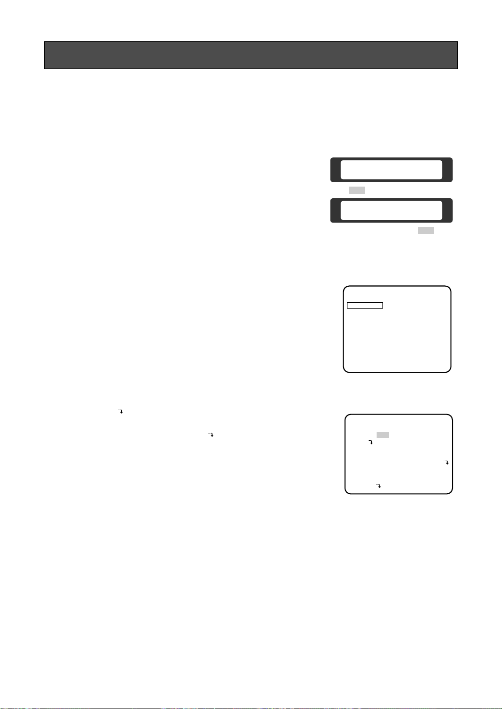
■ Menu Display
● Setup Menu Display
1. Select the number of the camera you want to set up and a monitor
to display the SET UP MENU.
2. Display the D4 menu on the LCD by pressing the appropriate
cursor buttons.
3. Press the F1 button.
The SET UP MENU appears on the monitor.
4. To close the SET UP MENU, press the F4 button.
Note:
Do not change the SET UP MENU (for camera communication) settings of the WV-CSR650 except CAMERA*. If those
settings are changed, the camera and the controller may get
out of control.
● Submenu Display
The items marked can be selected/changed on the submenu.
• Move the cursor to an item with the mark and press the CAM
(SET) key. The submenu is displayed.
Note:
When you use the WV-CSR650, move the cursor to CAMERA
on the SET UP MENU for camera communication and press
the CAM (SET) key. The SET UP MENU for camera setting
appears in the display.
D4 menu
Camera Set Up Menu
On Exit
F2 F3 F4
F1
Camera Set Up Menu
Res A.Res Exit
F1 F2 F3 F4
Setup menu
for camera communication
(only for WV-CSR650)
*** SET UP MENU ***
CAMERA*
UNIT NUMBER 1
BAUD RATE 19200
DATA BIT 8
PARITY BIT NONE
XON/XOFF NOT USE
WAIT TIME OFF
ALARM DATA AUTO 2
DELAY TIME OFF
COM. SET UP DISABLE
Setup menu
(for camera setting)
*** SET UP MENU ***
PRESET 1*
MAP
HOME POSITION 15
SELF RETURN 10MIN
AUTO MODE AUTO PAN
FLIP-A-CHIP ON
LOCAL/REMOTE LOCAL
CAMERA
■ RS485 Set Up
● Initial camera communication parameters
• Confirm the communication parameters of the matrix switcher (WJ-SX550A), and display the camera
SET UP MENU.
The initial camera communication parameters are shown in the illustration above.
The other parameters are as follows:
Daisy : OFF
Camera In Number : 1
F/H Duplex : Full
- 10 -
 Loading...