

Panasonic WS-TN06N, WU-ZS001E, WS-2360N, WS-TN05N, WS-2335N User Manual
...
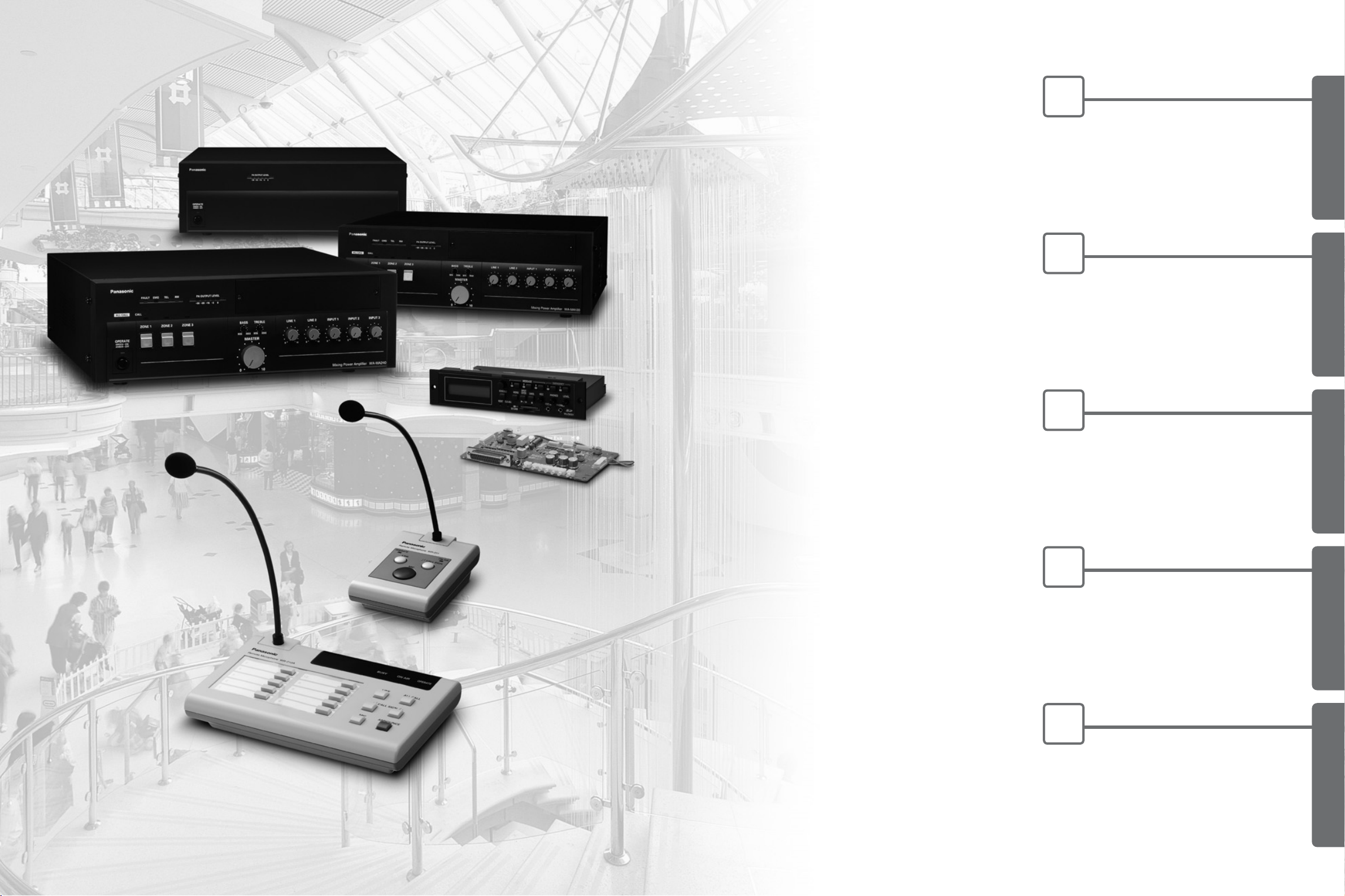
Power Amplifier & Mixer Integrated System
DESIGN HANDBOOK
2 3
TABLE
OF
CONTENTS
1
Concept
P4 ~ P7
Mixing Power Amplifier
WA-MA120N (120W)
Remote Microphone
WR-201E
Remote Control Microphone
WR-210AE
Surveillance Unit
WU-ZS001E
Sound Message Unit
WU-ZM001E
Mixing Power Amplifier
WA-MA240N (240W)
Booster Power Amplifier
WA-BA240N (240W)
CONCEPT
2
System Examples
P8 ~ P15
SYSTEM EXAMPLES
3
Connections
P16 ~ P43
CONNECTIONS
4
Products
P44 ~ P73
PRODUCTS
5
Block Diagrams
P74 ~ P79
BLOCK DIAGRAMS
CONCEPTSYSTEM EXAMPLESCONNECTIONSPRODUCTSBLOCK DIAGRAMS
5
1
CONCEPT
CONCEPT
CONCEPT SYSTEM EXAMPLES CONNECTIONS PRODUCTS BLOCK DIAGRAMS
4
1
CONCEPT
CONCEPT
All-in-One Mixer and Amp
From the simplest to the most complex public address needs, the WA-MA120N
and WA-MA240N have what it takes. These mixing power amplifiers
combine multiple inputs with assigned priorities and call
signs to provide the flexibility required for applications
ranging from schools and business facilities, factory,
office and religious buildings. To ensure more
efficient and reliable communication, options including
program broadcasting and troubleshooting.
The Public Address System Made it Easy.
2-channel Broadcast
Background music and announcement transmission can be
transmitted independently to any of three zones, with
background music transmitted to one zone and
announcements transmitted to another zone.
*2-channel broadcast requires the optional WA-BA240N Booster Power Amplifier
Up To Four Remote Microphones
Up to four (4) WR-210AE remote microphones can be used
to broadcast from remote locations. These remote
microphones can be used for individual, group, all-at-once or
simultaneous broadcast.
Add Up To 30 Zones
Depending on scale of application systems may include up to
ten (10) WA-MA120N or WA-MA240N mixing power
amplifiers for expansion to up to 30 zones.
Broadcast Simultaneously To
Multiple Remote Areas
For example, facilities with multiple buildings can have a
WA-MA120N or WA-MA240N installed in each building. Via
the simultaneous broadcast BUS I/O connector, broadcasts
can be directed to selected all buildings at once.
Program Broadcast
With the optional WU-ZM001E Sound Message Unit, an
SD memory card can be used to store MP3 data to be
broadcast for a week at specified days and times. The SD
memory card holds 100 messages.
Troubleshooting
The optional WU-ZS001E Surveillance Unit checks at
preset intervals (or 24-hours a day) for overheating and
sound and speaker irregularities.
Reliable Cooling
Cooling fan control is provided by two thermal sensors
monitoring temperatures inside the case.
Energy Saving Design
This mixing power amplifier uses Class-H amplifier
technology developed by RAMSA, the Panasonic
Professional Audio Group, to minimize power consumption.
Message for ZONE 1 only,
and BGM continues for
ZONE 2 and 3.
ZONE 3
(BGM)
ZONE 2
(BGM)
ZONE 1
(BGM)
Background
music
continue
Attention...
ZONE 3
(BGM)
ZONE 2
(BGM)
ZONE 1
(Message)
NO.1 (Master)
WR-210AE
(up to 4 units)
NO.2 (Slave)
NO.10 (Slave)
1
2
3
4
5
6
28
29
30
ZONES
ZONE 3
[F3 Restaurants Floor]
ZONE 2
[F2 Apparel Floor]
ZONE 1
[F1 Grocery Floor]
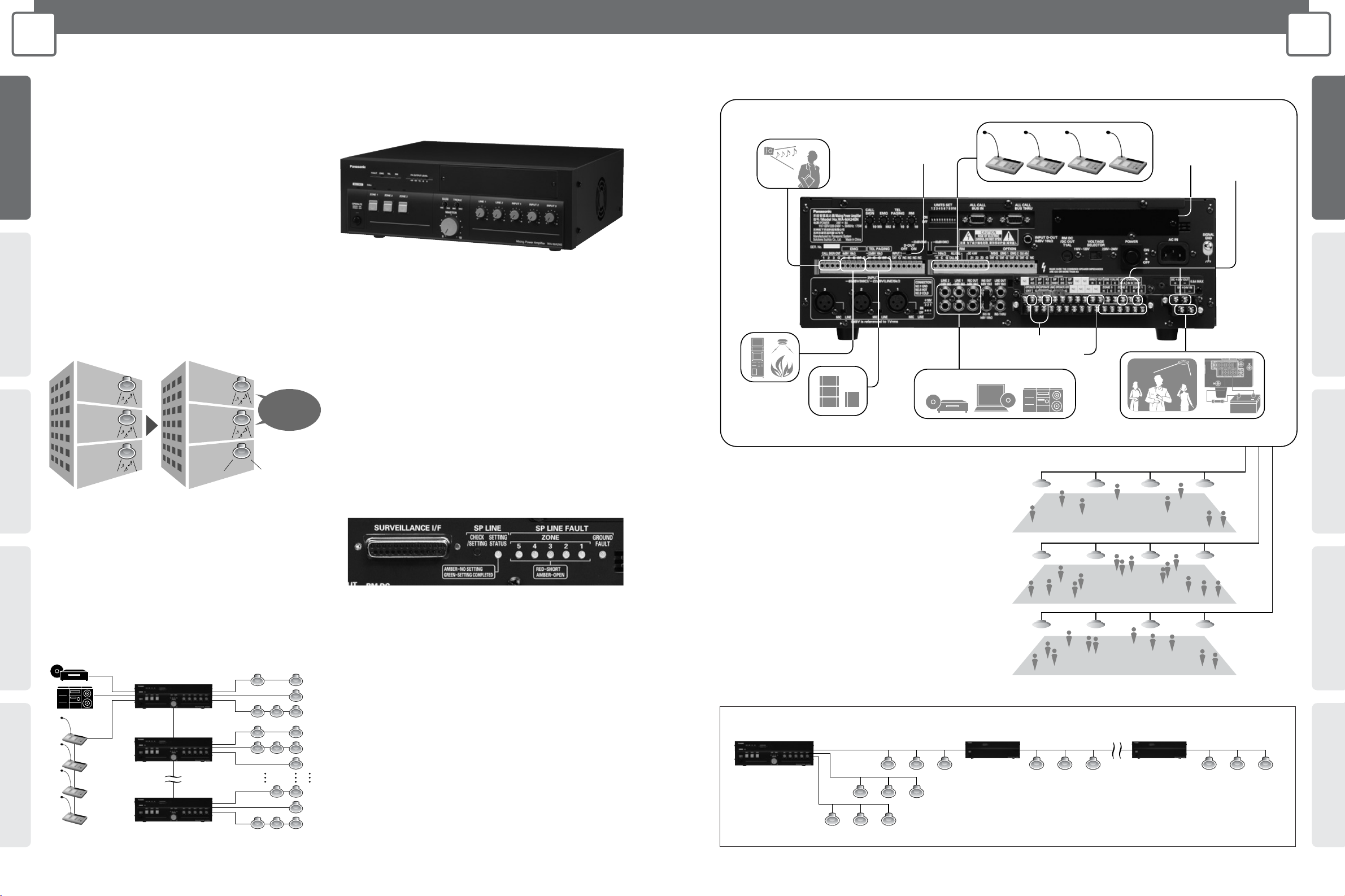
Up to four (4) Remote Microphones
CD/MD Player or Other Background Music Source Backup Battery in Case of Power Failure
Connect Telephone
Paging
Emergency
Equipment
Switch to on for 2-channel
Broadcast from Input 1
Select Call Sign
(1) Rising 4 sounds, (2) Falling
4 sounds, (3) Two sounds, one time
Surveillance Unit Slot
Low Impedance Speaker
High Impedance Speaker
Attenuator Override
DC+24V
Basic Example
Priority Broadcast Feature Priorities are as follows.
(1) Emergency announcement
(2) Telephone paging, input 1, message from
Sound Message Unit
(3) Remote microphone
(4) input 2, 3 and Line 1, 2
Higher priority broadcasts preempt lower
priority broadcasts.
*When (2) and (4) occur simultaneously and inputs compete, mixing occurs.
Sound level can be adjusted.
Cable Extension
* While there are no restrictions on attaching a WA-BA240N to your
network, sound quality may deteriorate at distant locations.
WA-MA120N
WA-MA240N
WA-BA240N
WA-BA240N
ZONE1
ZONE2
ZONE3
When you need to broadcast to distant locations, the optional Booster Power Amplifier allows you to extend the speaker cable as far as necessary.
6 7
1
CONCEPT
BASIC SYSTEM DIAGRAM
1
CONCEPT
BASIC SYSTEM DIAGRAM
CONCEPT SYSTEM EXAMPLES CONNECTIONS PRODUCTS BLOCK DIAGRAMS
CONCEPTSYSTEM EXAMPLESCONNECTIONSPRODUCTSBLOCK DIAGRAMS
6 7
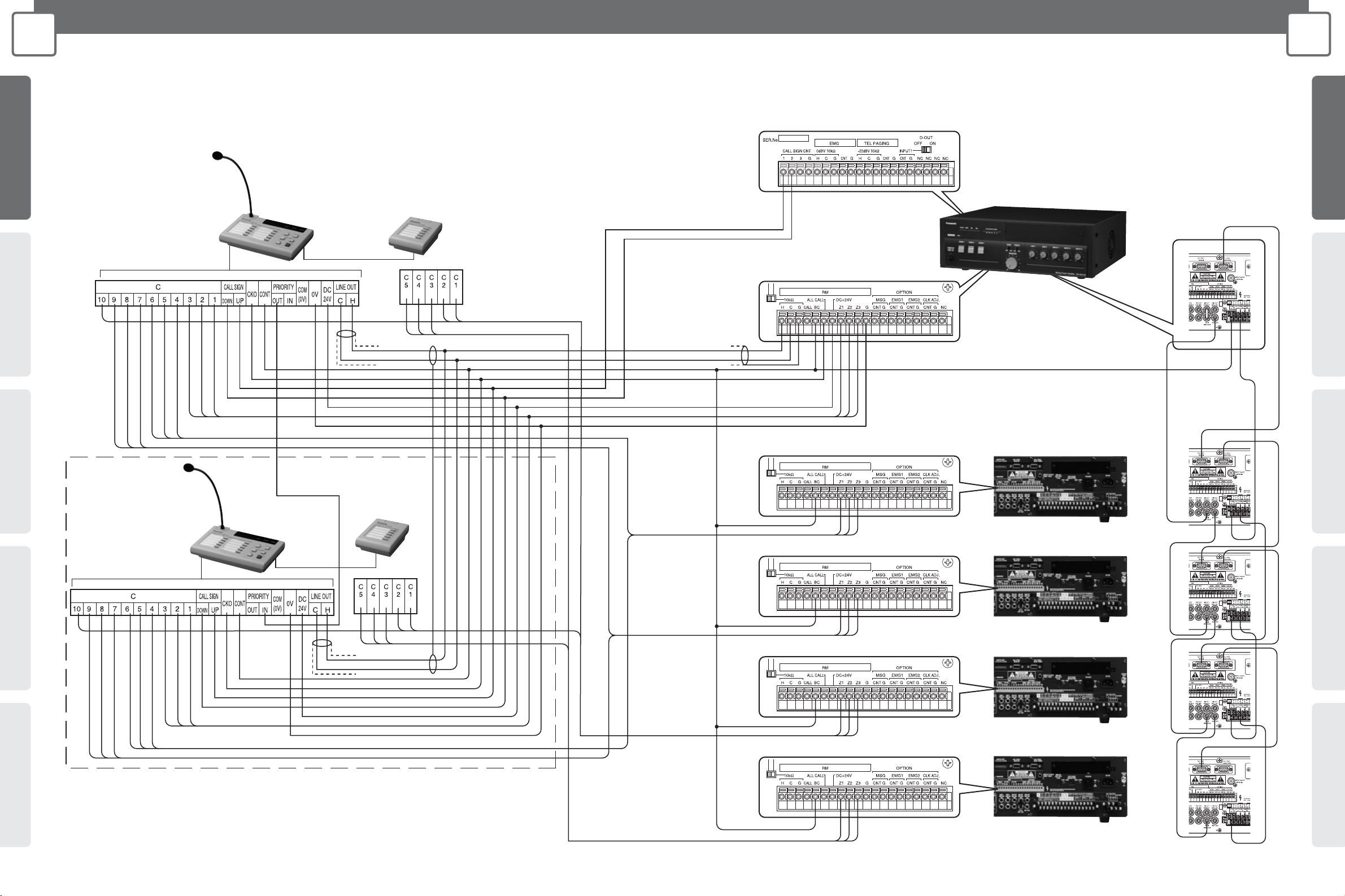
Mixing Power Amplifier (WA-MA120N/240N) Connection
Schematic diagram of Remote Microphone with Extension Unit (WU-RM205E) connected for announcements on 15 channels.
The illustration in the broken line frame shows how to connect more than one Remote Microphones to Mixing Power Amplifier.
Refer to this illustration for method of connecting up to 4 Remote Microphones.
Master
Slave
Important:
• Refer to page 38 and the Operating Instructions for the Amplifier for information on connecting Mixing Power Amplifiers
(WA-MA120N, WA-MA240N).
• Use a crimp connector to group wires together if you need to connect more than one wire to the terminal.
* Announcements can be made on a maximum of 30 channels by connecting 4 Extension Units, for a combination of 10 channels on the
Remote Microphone and 20 channels on the Extension Units.
Remote Control
Microphone
WR-210AE
Extension Unit
WU-RM205E
Mixing Power Amplifier
WA-MA120N/240N
Amplifier (Master)
Remote Control
Microphone
WR-210AE
WA-MA120N/240N
Extension Unit
WU-RM205E
Amplifier (Slave 1)
WA-MA120N/240N
Amplifier (Slave 2)
WA-MA120N/240N
Amplifier (Slave 3)
WA-MA120N/240N
Amplifier (Slave 4)

8 9
2
SYSTEM EXAMPLES
DEPARTMENT STORE
Department Store Outline
2
SYSTEM EXAMPLES
FACTORY
CONCEPT SYSTEM EXAMPLES CONNECTIONS PRODUCTS BLOCK DIAGRAMS
CONCEPTSYSTEM EXAMPLESCONNECTIONSPRODUCTSBLOCK DIAGRAMS
System Diagram
Factory Outline
FEATURES
KEY POINT
• Broadcasts background music.
• Mutes background music when remote microphone is in use.
• Extend the system throughout the entire building with
additional amplifiers.
• Broadcast of instructions at regular intervals.
• In an emergency, an emergency message is broadcast to all
zones.
FEATURES
KEY POINT
• Priority Levels (1) to (4)
• Allows all-zone announcements from master amplifier to slave
amplifier.
• The remote microphone can be used for making
announcements to specific zones and all-zone announcements.
Individual announcements x 7 zones
General announcements x 1(All zones)
• Cascade Connection
Increases expansion capability to include all-zone broadcast to
separate facilities.
• 2-channel Broadcast
Transmit a message only to the zone that needs it.
• Additional Amplifier Connection
Supports additional amplifiers when changes in layout require
additional capacity.
• Remote-controlled Microphone Connection
Allows remote microphones to be used for individual, group, allat-once emergency, and simultaneous 2-channel broadcasts.
• Other Features
A chime is built into the master amplifier unit. The optional
Sound Message Unit supports configuration of systems for
regular broadcasts or simple emergency announcements.
• Remote-controlled Microphone Connection
Allows remote microphones to be used for individual, group, allat-once emergency, and simultaneous 2-channel broadcasts.
• Cascade Connection
Allows added amplifier capacity and additional speaker circuits.
• Simple Emergency Broadcast Announcements
Adding the optional Sound Message Unit to the master unit
allows broadcast of emergency instructions and also supports
turning off power to local amplifiers.
• Other Features
A chime is built into the master amplifier unit. The optional
Sound Message Unit supports configuration of systems for
regular broadcasts or simple emergency announcements.
System Diagram
CONCEPTSYSTEM EXAMPLESCONNECTIONSPRODUCTSBLOCK DIAGRAMS
11
2
SYSTEM EXAMPLES
SCHOOL
CONCEPT SYSTEM EXAMPLES CONNECTIONS PRODUCTS BLOCK DIAGRAMS
10
2
SYSTEM EXAMPLES
RESIDENCE
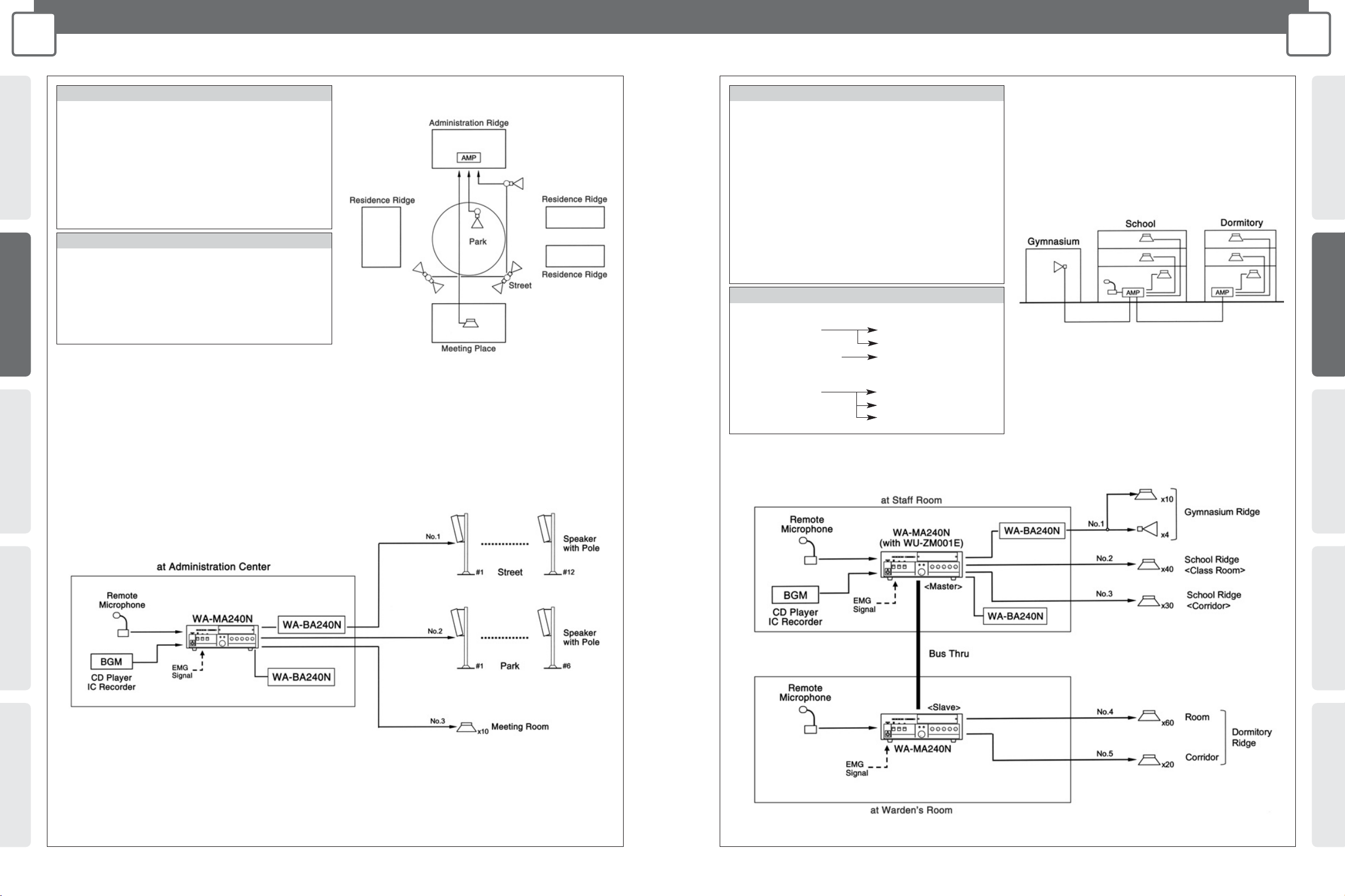
Residence Outline
System Diagram
School Outline
System Diagram
FEATURES
KEY POINT
• Pages can be directed to individual zones.
• Broadcasts background music
• Chimes can be broadcast at regular intervals.
• In an emergency, an emergency message is broadcast to all
zones.
• WA-BA240N supplementary amplifier can be added for areas
where amplifier capacity is insufficient.
• Remote-controlled Microphone Connection
Allows remote microphones to be used for individual, group, allat-once emergency, and simultaneous 2-channel broadcasts.
• Additional Amplifier Connection
When additional capacity is needed.
• Other Features
A chime is built into the main amplifier unit. The optional Sound
Message Unit supports configuration of systems for regular
broadcasts or simple emergency announcements.
FEATURES
KEY POINT
• Cascade Connection
Normal: Transmits individually to specific amplifiers.
Emergency: All-zone announcement.
• Remote-controlled Microphone Connection
Allows remote microphones to be used for individual, group, allat-once emergency, and simultaneous 2-channel broadcasts.
• Additional Amplifier Connection
Supports additional amplifiers when changes in layout require
additional capacity.
• Other Features
A chime is built into the master amplifier unit. The optional
Sound Message Unit supports configuration of systems for
regular broadcasts or simple emergency announcements.
• Normal usage (transmit to individual amplifiers).
• Emergency usage (all-zone announcement to whole facility).
Gymuasium Ridge
School Ridge
Dormitory Ridge
Staff Room
Warden’s Room
Gymuasium Ridge
School Ridge
Dormitory Ridge
Staff Room
CONCEPTSYSTEM EXAMPLESCONNECTIONSPRODUCTSBLOCK DIAGRAMS
13
2
SYSTEM EXAMPLES
HOTEL
CONCEPT SYSTEM EXAMPLES CONNECTIONS PRODUCTS BLOCK DIAGRAMS
12
2
SYSTEM EXAMPLES
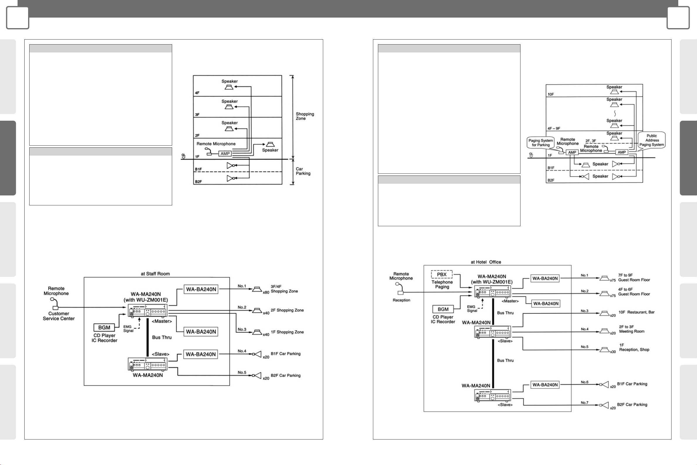
SHOPPING CENTER
Shopping Center Outline
System Diagram
Hotel Outline
System Diagram
FEATURES
KEY POINT
• Broadcasts background music.
• Mutes background music when remote microphone is in use.
• Extend the system throughout the entire building with
additional amplifiers.
• Broadcast of instructions at regular intervals.
• In an emergency, an emergency message is broadcast to all
zones.
• Remote-controlled Microphone Connection
Allows remote microphones to be used for individual, group, allat-once emergency, and simultaneous 2-channel broadcasts.
• Cascade Connection
Allows added amplifier capacity and additional speaker circuits.
• Simple Emergency Broadcast Announcements
Adding the optional Sound Message Unit to the master unit
allows broadcast of emergency instructions and also supports
turning off power to local amplifiers.
• Other Features
A chime is built into the master amplifier unit. The optional
Sound Message Unit supports configuration of systems for
regular broadcasts or simple emergency announcements.
FEATURES
KEY POINT
• Broadcasts background music.
• Mutes background music when remote microphone is in use.
•
With additional amplifiers, broadcasts can reach the whole facility.
• In an emergency, an emergency message is broadcast to all
zones.
• Emergency input can turn off power to local amplifiers.
Public Address Paging System
• 2-channel Broadcast
Transmit a message only to the zone that needs it.
• Remote- controlled Microphone Connection
Allows remote microphones to be used for individual, group, allat-once emergency, and simultaneous 2-channel broadcasts.
• Simple Emergency Broadcast Announcements
Adding the optional Sound Message Unit to the master unit
allows broadcast of emergency instructions and also supports
turning off power to local amplifiers.
Paging System for Parking
• 2-channel Broadcast
Transmit a message only to the zone that needs it.
• Remote- controlled Microphone Connection
Allows remote microphones to be used for individual, group, allat-once emergency, and simultaneous 2-channel broadcasts.
CONCEPTSYSTEM EXAMPLESCONNECTIONSPRODUCTSBLOCK DIAGRAMS
15
2
SYSTEM EXAMPLES
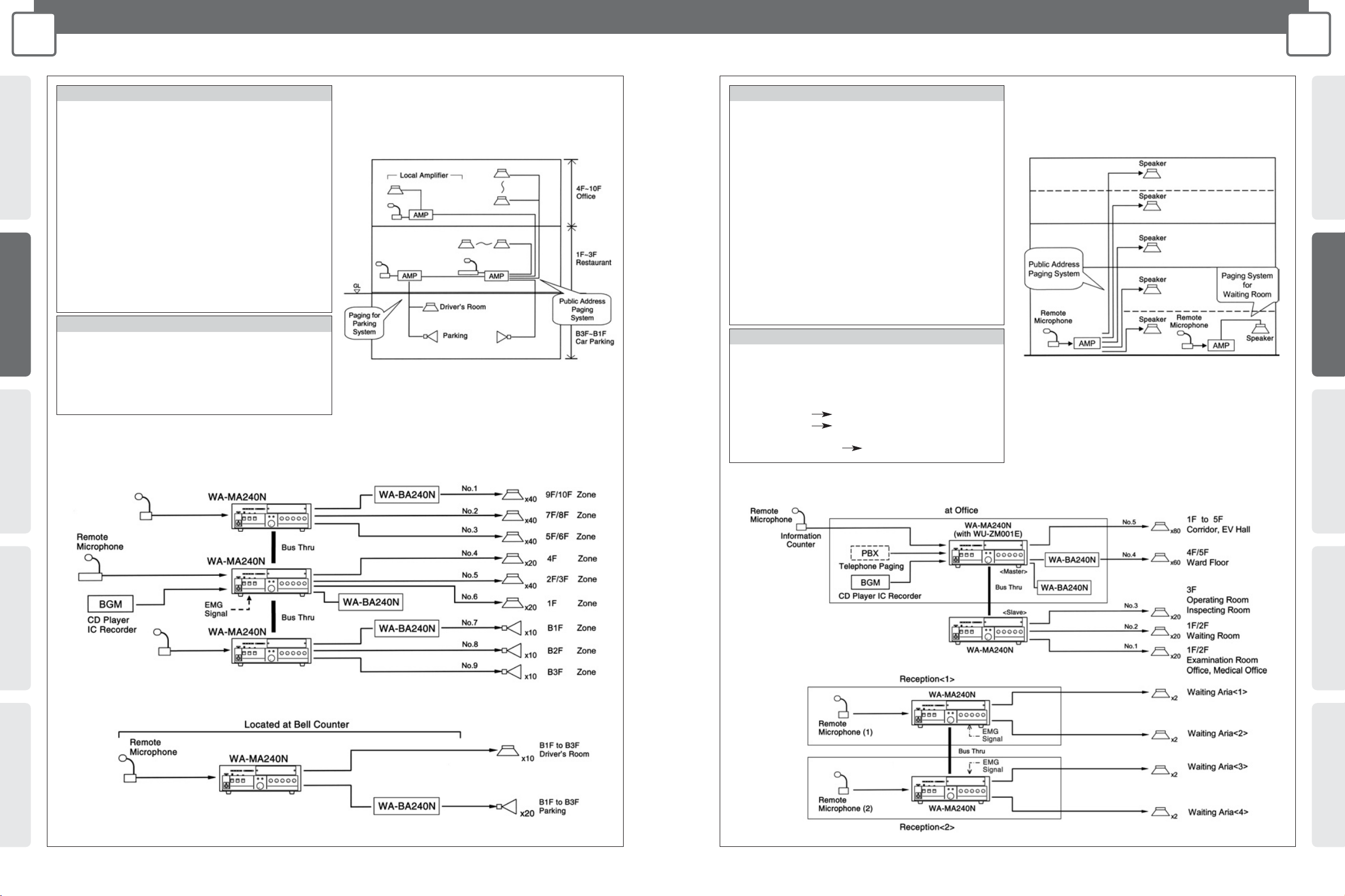
HOSPITAL
CONCEPT SYSTEM EXAMPLES CONNECTIONS PRODUCTS BLOCK DIAGRAMS
14
2
SYSTEM EXAMPLES
COMPOUND BUILDING
Compoumd Building Outline
System Diagram
Hospital Outline
System Diagram
Public Addres Paging System for whole facility
Public Addres Paging System
Paging System for Waiting Room
Paging System for Parking
FEATURES
KEY POINT
• Mutes background music when remote microphone is in use.
• Emergency input turns off power to local amplifiers.
•
Amplifier capacity can be increased by connecting additional amplifiers.
• Remote microphone can be used for separate broadcasts
(driver waiting room or parking garage).
• In emergencies, DC 24V input shuts down amplifiers.
Public Address Paging System for whole facility
• 2-channel Broadcast
Transmit a message only to the zone that needs it.
• Cascade Connection
Allows added amplifier capacity and additional speaker units.
• Simple Emergency Broadcast Announcements
Adding the optional Sound Message Unit to the master unit
allows broadcast of emergency instructions and also supports
turning off power to local amplifiers.
Paging System for Parking
• 2-channel Broadcast
Transmit a message only to the zone that needs it.
• Cascade Connection
Allows added amplifier capacity and additional speaker circuits.
FEATURES
KEY POINT
• Background music broadcast to hallways and elevator lobbies.
• Mutes background music when remote microphone is in use.
•
Emergency message is broadcast in response to emergency input.
•
Paging outpatients waiting to see the doctor by next-in-queue numbers.
• Normal usage (Paging from individual amplifiers)
Reception <1> Waiting Area <1> <2>
Reception <2> Waiting Area <3> <4>
• All zone (Paging from one amplifier)
Reception <1> or <2> Waiting Area <1> <2> <3> <4>
Public Address Paging System
• 2-channel Broadcast
Transmit a message only to the zone that needs it.
• Cascade Connection
Allows added amplifier capacity and additional speaker circuits.
• Simple Emergency Broadcast Announcements
Adding the optional Sound Message Unit to the master unit
allows broadcast of emergency instructions and also supports
turning off power to local amplifiers.
Paging System for Waiting Room
• Remote-controlled Microphone Connection
Allows remote microphones to be used for individual, group, allat-once emergency, and simultaneous 2-channel broadcasts.
• Cascade Connection
Increases expansion capability to include all-zone broadcast to separate facilities.

CONCEPTSYSTEM EXAMPLESCONNECTIONSPRODUCTSBLOCK DIAGRAMS
17
3
CONNECTIONS
WA-MA120N/WA-MA240N
CONCEPT SYSTEM EXAMPLES CONNECTIONS PRODUCTS BLOCK DIAGRAMS
16
3
CONNECTIONS
WA-MA120N/WA-MA240N
INSTALLATION
AC Voltage Setting
• Before plugging the AC power plug into the mains, make sure the VOLTAGE
SELECTOR switch on the back of the Amplifier is in the proper position.
• The factory preset is 220 V to 240 V. The Amplifier will not operate correctly if the
VOLTAGE SELECTOR is set to 220 V to 240 V while the AC voltage is 110 V to 120 V.
CONNECTIONS
Important:
• The Amplifier's output power cannot be increased if multiple Amplifiers (or WA-BA240N Booster Power
Amplifier) are inputting and outputting the same signal "in parallel operation" because it will short
circuit. Absolutely do not connect the Amplifiers together in parallel operation, doing so may result in a
malfunction.
Backup for AC Power Cut
• Do not use UPS (Uninterruptible Power Supply) as backup in case of AC power cut.
Use external batteries instead.
Replacing the Fuse
• If the fuse blow, replace it with a fuse that is the same shape and capacity. The wrong type of fuse
will be prone to blowing even under normal conditions, and creates the risk of danger if the
Amplifier malfunctions.
Rack Mounting
Precautions
External Battery Precautions
Note the following precautions when using an external battery.
• Make sure the external battery is a 24 V Lead Acid battery (or two 12 V batteries in series connection). Panasonic Corporation holds
no responsibility for any Amplifier fault operation or other inconveniences resulting from using any other batteries except that indicated
above.
•
Use the formula below to determine the battery capacity that is necessary to support the amount of operating time required. Note, however,
that the actual amount of operation time provided by a battery varies greatly in accordance with the Amplifier's signal output Level.
•
When connected to an external battery, the Amplifier will automatically switch to the battery power supply once the AC power supply is
cut off by turning off the POWER switch or due to power cut. The battery power is not cut off even when the POWER switch on the
back of the Amplifier is turned off. The battery power consumption continues even when both the OPERATE and the POWER switches
are off and the OPERATE indicator remains lit amber. Use the formula below to determine the battery life.
To save the power of the battery, switch off both the POWER and the OPERATE, remove the battery if the Amplifier is not in use for a long period.
•
No battery power will be consumed only if the AC power is connected. And the Amplifier has no built-in battery charger. Note that the battery
discharges even when it is not in use, so observe the battery's instructions and check the battery periodically. Be sure to remove the battery
from the Amplifier before charging. And charge the battery properly according to the instructions of the battery and the battery charger.
•
The Amplifier operates normally with the battery voltage over 21 V, and audio output malfunction may occur if the voltage is lower than 21 V.
Battery Capacity [AH] = Amplifier Normal DC Consumption Current [A]* x Required Operating Time [H]
* Based on IEC60065 standards. Refer to the SPECIFICATIONS (page 48).
Battery Life [H] = Battery Capacity [AH] ÷ Amplifier Standby DC Consumption Current [A]*
* Please refer to the SPECIFICATIONS (page 48).
WA-MA120N: 15 A
WA-MA240N: 30 A
Cautions:
• Refer all work related to the installation and maintenance of the external battery to qualified service personnel or system installers.
• Be sure to turn off power (AC) before installing or removing a battery. To protect the battery, provide one of the fuses shown below between
the battery + terminal and the Amplifier's + terminal.
Take care to ensure proper battery polarity and to avoid shorts while working.
Installing Rack Mounting Brackets
• Installing the supplied rack mounting brackets lets you
configure the Amplifier for rack mounting.
1. Remove the screws (M5 x 16) from both
sides of the Amplifier.
2. Use the four screws (M5 x 16) to attach
the rack mounting brackets.
• Also remove the four rubber feet on the bottom of the
Amplifier by using a flat blade screwdriver to pry out the
pins that hold the feet in place.
VOLTAGE SELECTOR
switch
Blank
Panel
Blank
Panel
PA
Amplifier
PA
PA
OUTIN
G (Ground)
H (Hot)
C (Cold)
3
2
1
Screw
Spring washer
3 (Cold)
2 (Hot)
1 (Ground)
Hot
Ground
Cables and Connectors
Cable with XLR-3-12 Type (Male) Connector
Use this type of cable to connect to inputs 1 through 3. Use a connector that is wired pin 2 hot.
Cable with RCA Pin Plug
Use this type of cable to connect to LINE 1, LINE 2, REC OUT, LINE OUT, INPUT D-OUT, and INS IN/THRU/OUT.
Cable with D-sub 9 pin (Male) Connector on both Ends (inch-pitch screw)
Use this type of cable to link the ALL CALL BUS connectors when connecting multiple Amplifier units together.
Removing the Terminal Cover
1. Loosen the screw that secures the
terminal cover.
2. Remove the terminal cover.
ALL CALL BUS COLD
ALL CALL BUS HOT
GND
GND
GND
Control Terminal
Control Terminal
Control Terminal
Control Terminal
ALL CALL BUS COLD
ALL CALL BUS HOT
GND
GND
GND
Control Terminal
Control Terminal
Control Terminal
Control Terminal
Pin No. Pin No. Pin No. Pin No.
Signal Name Signal Name
Amplifier A
ALL CALL BUS THRU
Amplifier B
ALL CALL BUS IN
Shielded Cable
D-sub 9 pin (Male) connector
(inch-pitch screw)
D-sub 9 pin (Male) connector
(inch-pitch screw)
1
2
6
7
8
9
3
4
5
1
2
6
7
8
9
6
7
8
9
3
4
5
1
2
3
4
5
6
7
8
9
1
2
3
4
5
• Use a straight cable with all pins wired. Be sure to use shielded cable only for audio signal connections.
• General RS422 cable can be used for short distances of a few metres.
CONCEPTSYSTEM EXAMPLESCONNECTIONSPRODUCTSBLOCK DIAGRAMS
19
3
CONNECTIONS
WA-MA120N/WA-MA240N
CONCEPT SYSTEM EXAMPLES CONNECTIONS PRODUCTS BLOCK DIAGRAMS
18
3
CONNECTIONS
WA-MA120N/WA-MA240N
LINE1,2, INPUT2,3, REC OUT, INS IN/OUT Connections
• Use the connections shown below for a microphone or recording/playback equipment, effect device that is not equipped with
activation control (no-voltage make contact).
• For information about connecting INPUT1, refer to page 19.
• Change the INPUT1-3 MIC/ LINE switches setting in accordance with the equipment being connected.
• When connecting an effect device, remove the plug inserted in the RCA pin jack.
• Turn the INPUT1-3 +16 V ON/OFF switches on only when using an electret condenser microphone.
Important:
• Leaving this setting on when for any other type of connection will cause malfunction of the connected device or equipment.
• Changing this setting also can cause noise, so be sure to use the INPUT1-3 knobs on the front of the Amplifier to reduce volume before
changing this setting.
Audio Signal Source Equipment
(IC player, etc.)
Microphone, etc.
BGM Player
(CD player, etc.)
Recording/
Playback Equipment
(cassette deck, etc.)
Effect Device
(graphic equalizer, etc.)
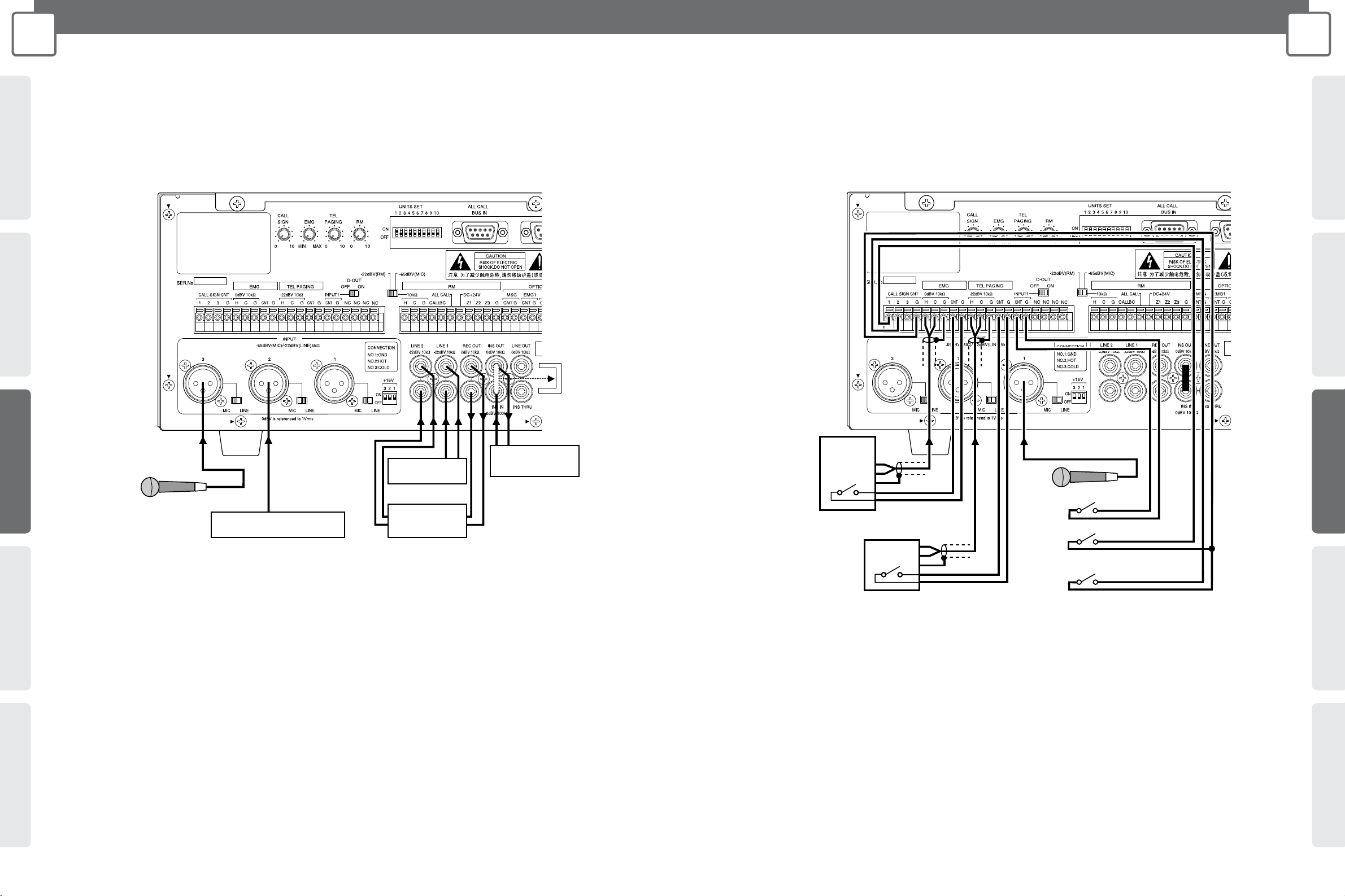
EMG, TEL PAGING, INPUT1 Connections
• Use the connections shown below for emergency announcement equipment or PBX, microphone that is equipped with
activation control (no-voltage make contact).
• Change the INPUT1 MIC/ LINE switches setting in accordance with the equipment being connected.
• Turn the INPUT1 D-OUT switch on when the INPUT 1 signal is being output from INPUT D-OUT for 2-channel announcement.
• Be sure to connect the connected device's no-voltage make contact terminal to each activation control terminal [CNT]. If they
are not connected, announcement priority control will not work or the audio signal of the equipment will not be output.
• When using a call tone, be sure to make contact with each input equipment's not-voltage make contact and then activate the
call tone. The call tone will not be announced if it is activated first.
• Turn the INPUT1 +16 V ON/OFF switch on only when using an electret condenser microphone.
Important:
• Leaving this setting on when for any other type of connection will cause malfunction of the connected device or equipment.
• Changing this setting also can cause noise, so be sure to use the INPUT1 knob on the front of the Amplifier to reduce volume before changing
this setting.
Microphone, etc.
Talk Switch (no-voltage make contact)
CALL SIGN Rising Switch
(no-voltage make contact)
CALL SIGN Falling Switch
(no-voltage make contact)
Emergency Announcement
Equipment
PBX, etc.
WA-MA120N
or
WA-MA240N
WA-MA120N
or
WA-MA240N
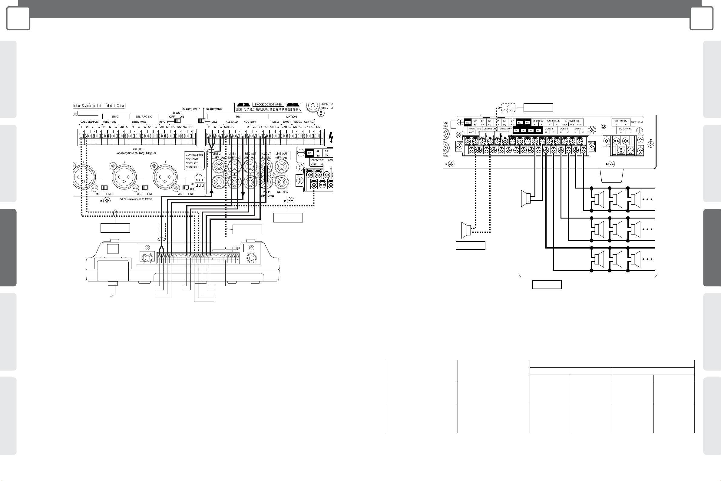
Speaker Connection Conditions Minimum Composition Impedance
Method WA-MA120N WA-MA240N
100 V 70 V 100 V 70 V
Speakers connected to Composition impedance 83 Ω 42 Ω 42 Ω 21 Ω
ZONE 1 or DIRECT OUT for one zone (120 W) (120 W) (240 W) (240 W)
only
Speakers connected to Composition impedance 83 Ω 42 Ω 42 Ω 21 Ω
multiple zones and DIRECT of all zones (120 W) (120 W) (240 W) (240 W)
OUT, and use
simultaneously
CONCEPTSYSTEM EXAMPLESCONNECTIONSPRODUCTSBLOCK DIAGRAMS
21
3
CONNECTIONS
WA-MA120N/WA-MA240N
CONCEPT SYSTEM EXAMPLES CONNECTIONS PRODUCTS BLOCK DIAGRAMS
20
3
CONNECTIONS
WA-MA120N/WA-MA240N
Remote Microphone (WR-210AE) Connection
• Up to four Remote Microphone units can be connected. For multiple connections, priority connection between Remote
Microphones is required. For more information, consult the operating instructions of the Remote Microphone.
• Confirm that the -22dBV (RM), -65dBV (MIC) switch is set to -22dBV (RM). If it isn't change the switch setting to -22dBV (RM).
Important 1:
Make this connection if you want to use call tones.
Important 2:
To perform 2-channel announcement from the Remote Microphone, connect the CALL terminal to any one of the C4 to C10 terminals of the
Remote Microphone. The individual switch (4-10) on the Remote Microphone that corresponds to the terminal number you connect to can be
used to switch to zone 1 interrupt during 2-channel announcement.
Important 3:
If you want the Amplifier to enter the operation mode when activation control is imposed from the Remote Microphone, branch from the cable
connected to the Remote Microphone's CONT terminal and connect to the Amplifier's OPERATE ON terminal.
Important 1
Important 2
Important 3
Remote Microphone
(WR-210AE)
Connect to
any terminal
C4 to 10C3
C2
C1
CONT
CKO
CALL SIGN DOWN
CALL SIGN UP
LINE OUT H
LINE OUT C
DC 24V
0V
Speaker Connection
• Use the connections shown below for connecting high-impedance or low-impedance loudspeakers.
Caution:
High-impedance and low-impedance loudspeakers cannot be connected at the same time. When using high-impedance loudspeakers, use
either 100 V or 70 V.
Important 1
Important 3
Low-impedance Loudspeakers
(up to 4Ω)
Important 2
High-impedance Loudspeakers
(up to the impedance shown in the table below)
Monitor,
etc.
Zone 1
Zone 2
Zone 3
Important 1:
When you want high-impedance loudspeaker output to by 70 V, change the position of the jumper as shown in the illustration. The factory
preset is 100 V.
Important 2:
Make sure that the parallel composition impedance of high-impedance loudspeakers does not fall below the values shown in the table below.
Important 3:
Make sure that the parallel composition impedance of low-impedance loudspeakers does not fall below 4 Ω. Up to two 8 Ω speakers or four
16 Ω speakers can be connected in parallel.
WA-MA120N
or
WA-MA240N
WA-MA120N
or
WA-MA240N
CONCEPTSYSTEM EXAMPLESCONNECTIONSPRODUCTSBLOCK DIAGRAMS
23
3
CONNECTIONS
WA-MA120N/WA-MA240N
CONCEPT SYSTEM EXAMPLES CONNECTIONS PRODUCTS BLOCK DIAGRAMS
22
3
CONNECTIONS
WA-MA120N/WA-MA240N
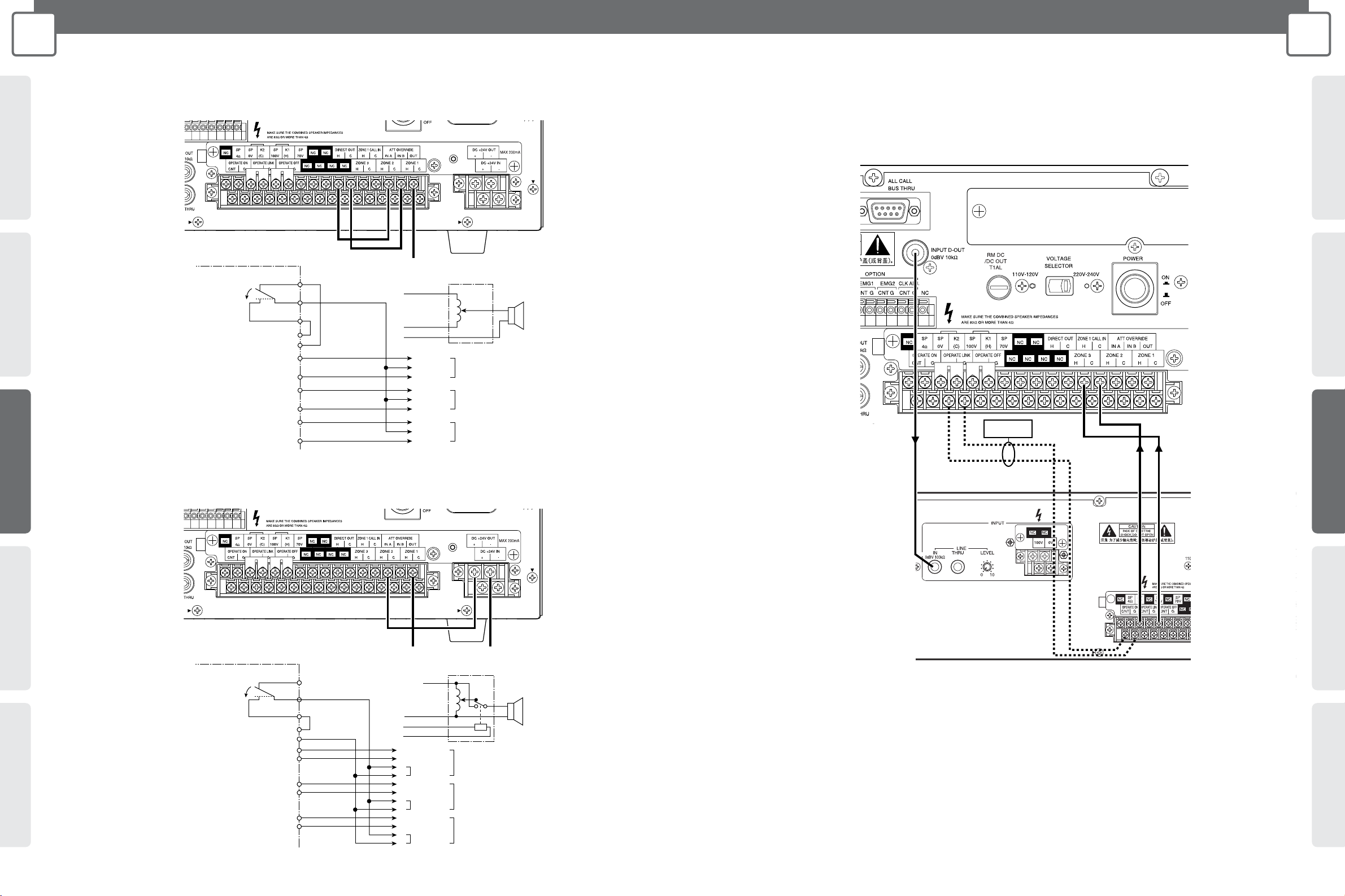
Connecting to Override External Attenuation during All-zone Announcement
(Using 3-wire connection)
Connecting to Override External Attenuation during All-zone Announcement
(Using 4-wire connection)
To external attenuator
Amplifier
All-zone
announcement ON
3-wire connection attenuator
(H)
IN B
OUT
IN A
H
HH
ZONE 1 OVERRIDE ZONE 1 External Attenuator
CC
HH
ZONE 2 OVERRIDE ZONE 2 External Attenuator
CC
HH
ZONE 3 OVERRIDE ZONE 3 External Attenuator
CC
C
DIRECT OUT
ATT OVERRIDE
(H)
(OVERRIDE)
(C)
(C)
To external attenuator
Amplifier
4-wire connection attenuator
All-zone
announcement ON
(H)
IN B
OUT
IN A
+
HH
CC
+
–
HH
CC
+
–
HH
CC
+
–
ZONE 1 External Attenuator
ZONE 2 External Attenuator
ZONE 3 External Attenuator
Relay Power
Relay Power
Relay Power
–
DC +24V OUT
ZONE 1
ZONE 2
ZONE 3
ATT OVERRIDE
(H)
(C)
(0V)
(+24V)
(C)
2-channel Broadcast Announcement Connection
• For 2-channel broadcast announcement, connect the WA-BA240N as shown below.
Important
• Use the gold plated plug (accessories of WA-BA240N) when connecting to LINE IN of WA-BA240N.
• Set the 2-channel announcement volume using the LEVEL knob of WA-BA240N.
Important:
If you want the WA-BA240N to turn on together with the WA-MA120N or WA-MA240N, connect the OPERATE LINK terminal to the OPERATE
ON terminal of the WA-BA240N.
Note:
If other amplifiers except WA-BA240N are required, select appropriate power amplifier rated output in accordance with ZONE1 speaker
impedance.
WA-MA120N
or
WA-MA240N
WA-MA120N
or
WA-MA240N
WA-BA240N
WA-MA120N
or
WA-MA240N
2524
CONCEPTSYSTEM EXAMPLESCONNECTIONSPRODUCTSBLOCK DIAGRAMS
3
CONNECTIONS
WA-MA120N/WA-MA240N
CONCEPT SYSTEM EXAMPLES CONNECTIONS PRODUCTS BLOCK DIAGRAMS
3
CONNECTIONS
WA-MA120N/WA-MA240N
Battery Connection
• Make sure the external battery is a 24 V Lead Acid battery (or two 12 V
batteries in series connection). Panasonic Corporation holds no
responsibility for any Amplifier fault operation or other inconveniences
resulting from using any other batteries except that indicated above.
• Use the formula below to determine the battery capacity that is
necessary to support the amount of operating time required. Note,
however, that the actual amount of operation time provided by a battery
varies greatly in accordance with the Amplifier's signal output level.
Operation On/Off Control
• Operation On Control and Operation Link Control
The Amplifier can be put into the operation mode externally by no-voltage make contact. The Amplifier can also cause other linked
equipment to enter operation mode when it enters the operation mode.
Important:
• In order for external operation control to be performed, the POWER switch on the back of the Amplifier must be ON, and the OPERATE switch
on the front must be OFF so the Amplifier is in the non-operation (standby) mode. The Amplifier's current operation/non-operation mode is
determined by the relationship between external control (no-voltage make contact) status and the Amplifier's OPERATE switch setting.
• Operation Off Control
The Amplifier can be put into the non-operation (standby) mode externally by no-voltage make contact. Use this capability when you want
to terminate business announcements from this Amplifier during announcements from external emergency announcement equipment.
Important:
• In order for operation off control to be performed, the POWER switch on the back of the Amplifier must be on, and the OPERATE switch on the
front must be ON so the Amplifier is in the operation mode. The Amplifier's current operation/non-operation mode is determined by the
relationship between external control (no-voltage make contract) status and the Amplifier's OPERATE switch setting.
Caution:
Be sure to turn off power (AC) before installing or removing a battery. To
protect the battery, provide one of the fuses shown below between the battery
+ terminal and the Amplifier's + terminal.
Battery Capacity [AH] = Amplifier Normal DC Consumption
Current [A]* x Required Operating Time [H]
* Based on IEC60065 standards. Refer to SPECIFICATIONS (page 48).
WA-MA120N: 15 A
WA-MA240N: 30 A
Take care to ensure proper battery polarity and to avoid shorts while working.
Caution
DC+24V
-
+
Other device power on link
No-voltage make contact
No-voltage make contact
Make
Amplifier's OPERATE
switch position
Break
Operation Mode
Operation Mode
Non-operation Mode
Operation Mode
Not Depressed (OFF)
Depressed (ON)
No-voltage make contact
Make
Amplifier's OPERATE
switch position
Break
Non-operation Mode
Non-operation Mode
Non-operation Mode
Operation Mode
Not Depressed (OFF)
Depressed (ON)
No-voltage make contact
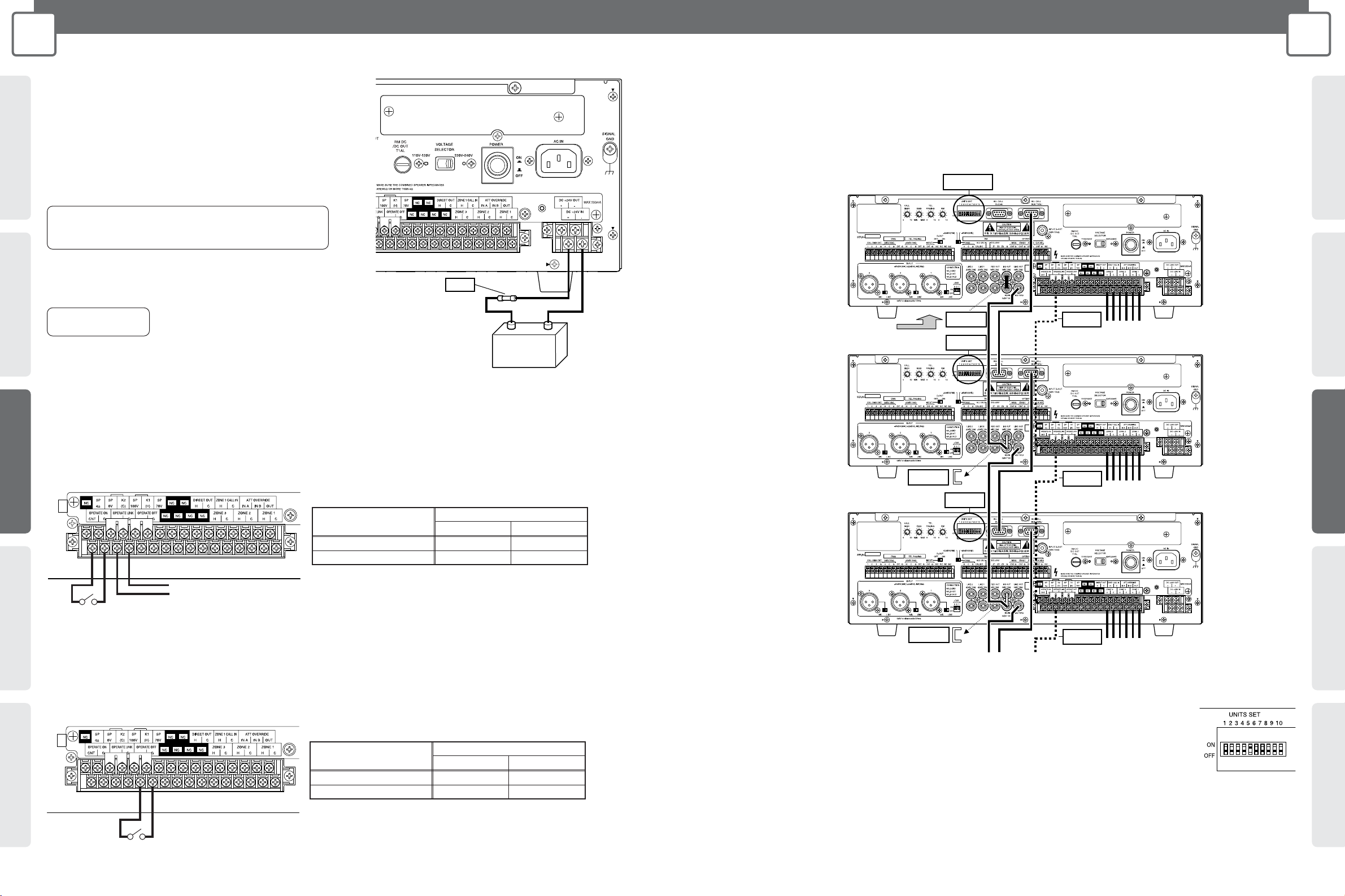
Zone Expansion Connection
• You can expand the number of zones using multiple Amplifier units.
• The illustration below shows the concept behind zone expansion. When connected this way the master Amplifier uses all
circuits but additional Amplifiers (Slave 1, 2 etc.) only use the built-in power amplifiers and zone output. This provides the
maximum rated output of the Amplifier for each group of three zones.
• The maximum number of Amplifiers (including the master and slaves) is 10, which means there can be to 30 zones.
Important 3
Important 3
Important 1
Important 2
Important 2
Amplifier (Master)
Amplifier (Slave 1)
Amplifier (Slave 2)
To Amplifier (Slave 3)
Connect to
each input device
To zone 1 to 3 speakers
To zone 4 to 6 speakers
To zone 7 to 9 speakers
Important 3
Important 1
Important 1
Important 2
• All connect the ALL CALL BUS connectors as shown in the illustration. All-zone announcement will not be possible if these
connectors are not connected.
Important 1:
On all of the Amplifiers, set the UNITS SET switches to the total number of Amplifiers.
Example: In the case there is one master and four slaves, set the UNITS SET switches of all of the Amplifiers to 5.
Important 2:
Never remove the plug from the RCA pin jack of the master Amplifier. No sound will be output in any of the zones
if you do. For all of the slave units, remove the plug and then do the connections.
Important 3:
Connect when you want operation control activated on all of the Amplifiers. For the connection shown in the illustration here, entering the
operation mode on the master also puts all of the slaves into the operation mode as well. Note, however, that the slaves must be in the standby
mode before the master goes into the operation mode.
For information about operation on/off control, see page 24.
 Loading...