

Page 1
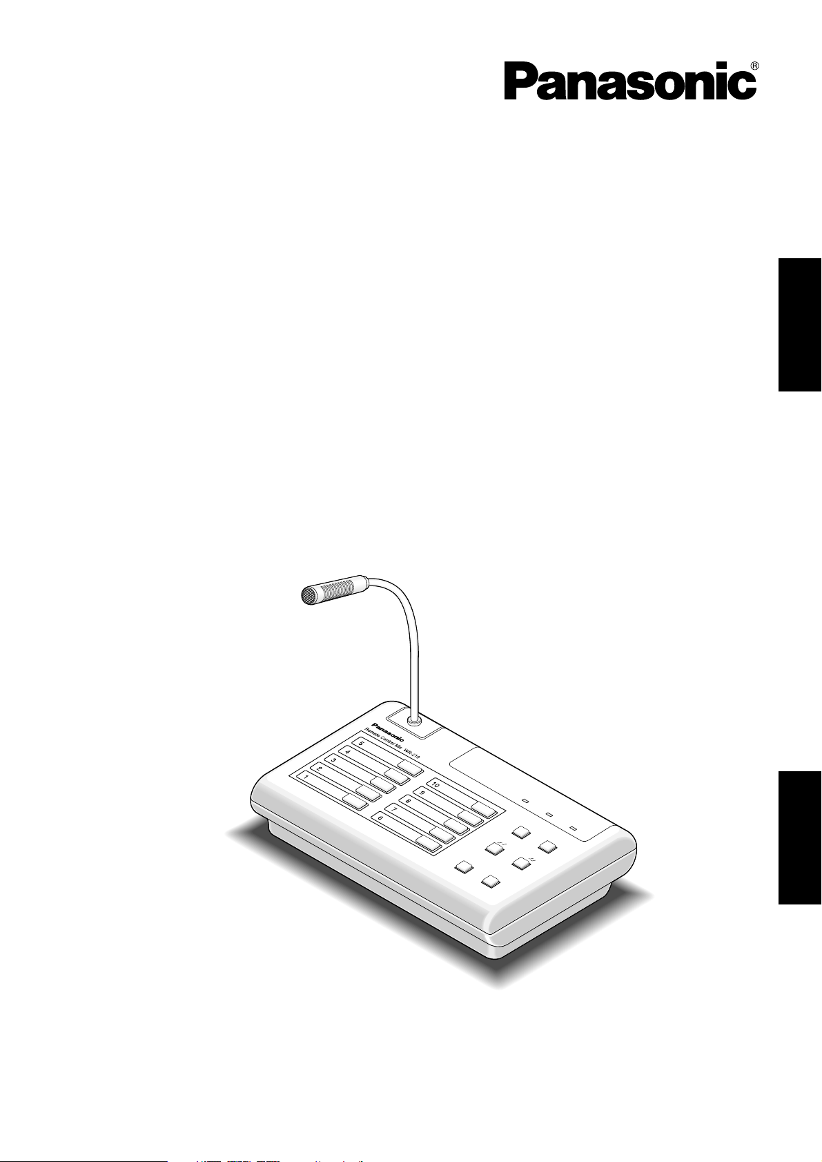
Model No.
WR-210E
遥控话筒
Remote Control Mic
Operating Instructions
使用说明书
Before attempting to connect or operate this product,
please read these instructions carefully and save this manual for future use.
中文
ENGLISH
B
U
S
Y
L
IN
E
O
N
A
IR
P
O
W
E
R
A
L
L
C
A
L
L
M
IC
ANNO
UNCE
CALL SIGN
Page 2
2
The serial number of this product may be found on the bottom of the unit.
You should note the serial number of this unit in the space
provided and retain this book as a permanent record of your
purchase to aid identification in the event of theft.
Model No. WR-210E
Serial No.
The lightning flash with arrowhead symbol, within an equilateral triangle, is
intended to alert the user to the presence of uninsulated "dangerous voltage"
within the product's enclosure that may
be of sufficient magnitude to constitute a
risk of electric shock to persons.
The exclamation point within an equilateral triangle is intended to alert the user
to the presence of important operating
and maintenance (servicing) instructions
in the literature accompanying the appliance.
CAUTION: TO REDUCE THE RISK OF ELECTRIC SHOCK,
DO NOT REMOVE COVER (OR BACK).
NO USER-SERVICEABLE PARTS INSIDE.
REFER SERVICING TO QUALIFIED SERVICE PERSONNEL.
CAUTION
RISK OF ELECTRIC SHOCK
DO NOT OPEN
WARNING: To prevent fire or electric shock hazard, do not expose this appliance to rain or moisture. The apparatus shall not be exposed to
dripping or splashing and that no objects filled with liquids, such as vases, shall be placed on the apparatus.
CONTENTS
PREFACE .................................................................................................................................................... 3
FEATURES .................................................................................................................................................. 3
PRECAUTION ............................................................................................................................................. 3
IMPORTANT NOTICE ................................................................................................................................. 4
MAJOR OPERATING CONTROLS AND THEIR FUNCTIONS .................................................................... 5
■ Front panel ........................................................................................................................................... 5
■ Rear panel ........................................................................................................................................... 5
ANNOUNCEMENT THROUGH REMOTE CONTROL MICROPHONE ........................................................ 6
■ For announcement in unison ............................................................................................................... 6
■ For individual announcement .............................................................................................................. 6
INSTALLATION............................................................................................................................................ 7
■ Wire length and diameter .................................................................................................................... 7
CABLE CONNECTION ............................................................................................................................... 8
■ Connection to WU-R55 ........................................................................................................................ 8
■ Connection to digital IC recorder ........................................................................................................ 9
■ Connection to line input and record output ......................................................................................... 9
PRIORITY ASSIGNMENT ............................................................................................................................ 10
■ No priority assigned ............................................................................................................................ 10
■ Individual priority ................................................................................................................................. 10
VOLUME ADJUSTMENT ............................................................................................................................ 11
TROUBLESHOOTING ................................................................................................................................ 11
ACCESSORIES ........................................................................................................................................... 12
SPECIFICATIONS ....................................................................................................................................... 12
ENGLISH VERSION
Page 3

3
PREFACE
PRECAUTION
• This product allows you to perform public address on
an individual system basis and in unison.
• Up to 10 channels available
• Do not attempt to disassemble the instrument. In order
to prevent electric shock, do not remove screws or covers. There are no user-serviceable parts inside. Do refer
all servicing to qualified service personnel.
• Do not abuse the instrument. Avoid striking, shaking,
etc. It could be damaged by improper handing or storage. Do handle the instrument with care.
• Do not use strong or abrasive detergents when cleaning the instrument body. Do use a dry cloth to clean the
instrument when dirty. In case the dirt is hard to
remove, use mild detergent and wipe gently.
• Do not expose the instrument to water or moisture, and
do not operate in wet area. Do take immediate action if
ever the instrument does become wet. Turn the power
off and refer servicing to qualified service personnel.
Moisture can damage the instrument and also create
the danger of electric shock.
• Do not use the instrument in an extreme environment
where high temperature or high humidity exist. Use the
instrument under conditions where temperatures are
within –10 °C - +50 °C, and humidity is below 95 %.
• The power source for this unit must be 24 V DC.
• Every necessary procedures with regard to install this
product should be made by qualified service personnel
or System Installers.
• 24 V DC only
• The recording output and the priority function are
equipped.
ENGLISH
FEATURES
• This product is desktop type.
• If the recording output terminal is connected to an
external recorder such as an IC recorder, you can
record your voice simply through the microphone.
• You can toggle audio input on and off with the microphone switch and the line switch.
• You can announce two types of call signs with the call
sign switch (if this product is connected to a rack type
emergency public address system).
• You can assign priorities to remote control microphones
(individual priority function). The usage status of remote
control microphones can be checked on the busy indicator and the on air indicator.
Page 4

4
IMPORTANT NOTICE
• Priorities should be assigned to announcements via the sound system to be connected to this product.
The following are announcement priorities in general (for an emergency public address system).
1. Emergency announcement
2. Urgent announcement
3. Business announcement (from remote control microphone, etc.)
• Press the announcement switch or the all call switch, wait for a second or more and make an announcement. (Some
sound systems take a few seconds before the systems are ready for announcement.)
• Displayed information
Please refer to the bottom of this product for identification, power source and other information.
Caution: If you touch the operation panel, an announcement may start. Therefore, when you take care of this unit, do not
touch the operation panel, or take care of it under proper circumstances.
Page 5
5
MAJOR OPERATING CONTROLS AND THEIR FUNCTIONS
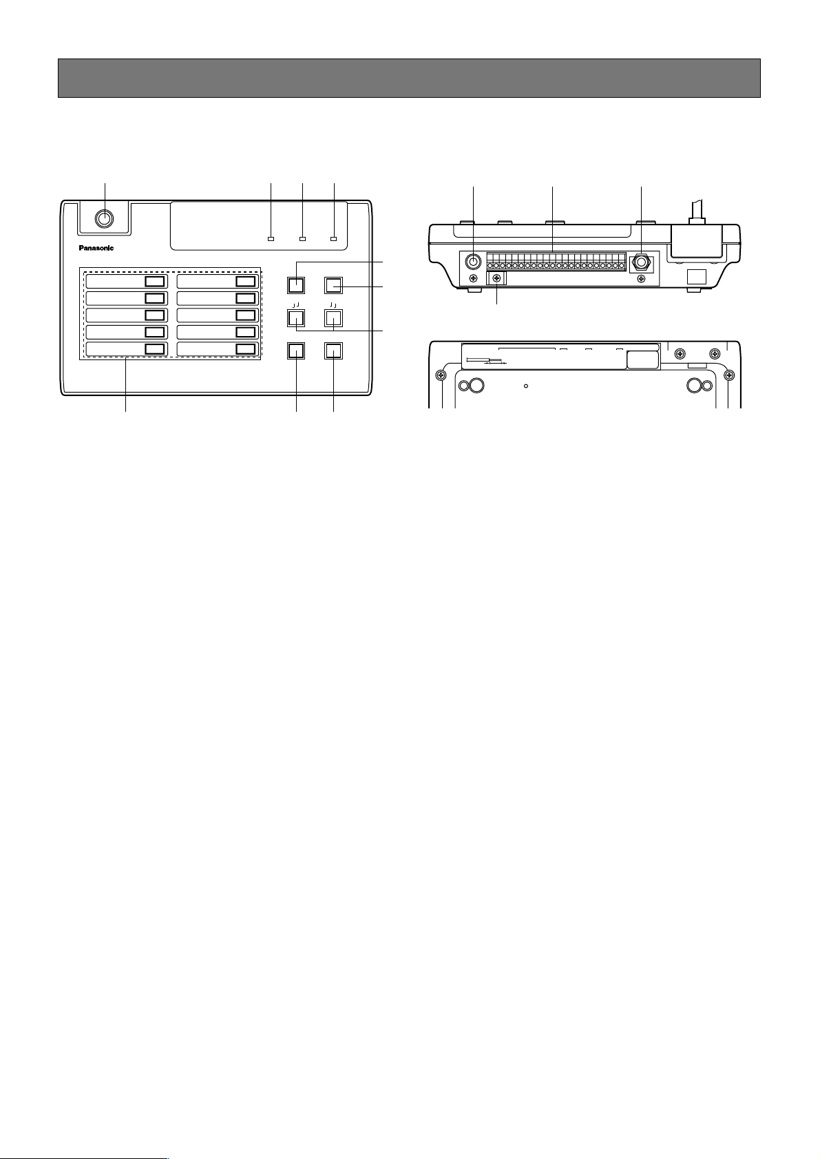
q Flexible microphone
You can aim the microphone at your favorite direction.
w Busy indicator (BUSY)
For priority announcement, this indicator lights up during public address is performed through other remote
control microphones. However, when the individual priority function is active, the indicators of higher priority
microphones do not light up during public address is
performed through a lower priority microphone.
e On air indicator (ON AIR)
Lights up during public address is performed with this
unit.
r Power indicator (POWER)
Lights up during 24 V DC is supplied to this unit.
t Line switch (LINE)
When announcing an audio program from the device
connected to the line input, press this switch.
y All call switch (ALL CALL)
When making an announcement to all blocks in unison
from this unit, press this switch. It is not necessary to
press the announcement switch to make an announcement in unison.
u Call sign switch (
T
T
CALL SIGNTT)
Makes the device connected to this unit (an emergency
public address system or a business public address
system) sound a call sign.
Note: Do not press the call sign up and down switches
simultaneously. Failure to observe this activates the
status of an announcement in unison.
i Announcement switch (ANNOUNCE)
When making an announcement with this unit, press
this switch. If you press this switch again, the
announcement will be finished.
o Microphone switch (MIC)
When making an announcement through the flexible
microphone, press this switch.
!0 Individual switches (1-10)
When making an announcement to a specific block,
press the corresponding switch.
!1 Line input (–2 dBV, 10 kΩ unbalanced)
Is connected to the audio output of an external line
device.
!2 Connection terminals
Are connected to emergency public address systems
(wall-mounted type/rack type) or business public
address systems.
!3 Record output (0 dBV, 10 kΩ unbalanced)
Is used when recording audio from the microphone of
this unit or a line device.
!4 Cable clamp
Is used when securing cables with the binding band
(supplied).
■ Front panel
Remote Control Mic WR-210
BUSY
LINE
ON AIR POWER
1
2
3
4
5
6
7
8
9
10
ALL CALL
CALL SIGN
MIC ANNOUNCE
q
wer
t
y
u
io!0
■ Rear panel
!4
!1 !2 !3
REC OUT
LINE IN
STRIPPING LENGTH 11mm
0dBV
-2dBV 10kΩ
COM
C24V0V
CKO CONT
C
21345678910
11mm
H
OUT INDOWN UP
(0V)
LINE OUT
DC
PRIORITYCALL SIGN
ACCEPTABLE WIRE GAGE
SOLID WIREø0.4 (AWG26)~ø1.2 (AWG16)
STRANDED WIRE0.3mm2~1.25mm2 (AWG16ELEMENT WIREø0.18MIN)
Page 6
6
ANNOUNCEMENT THROUGH REMOTE CONTROL MICROPHONE
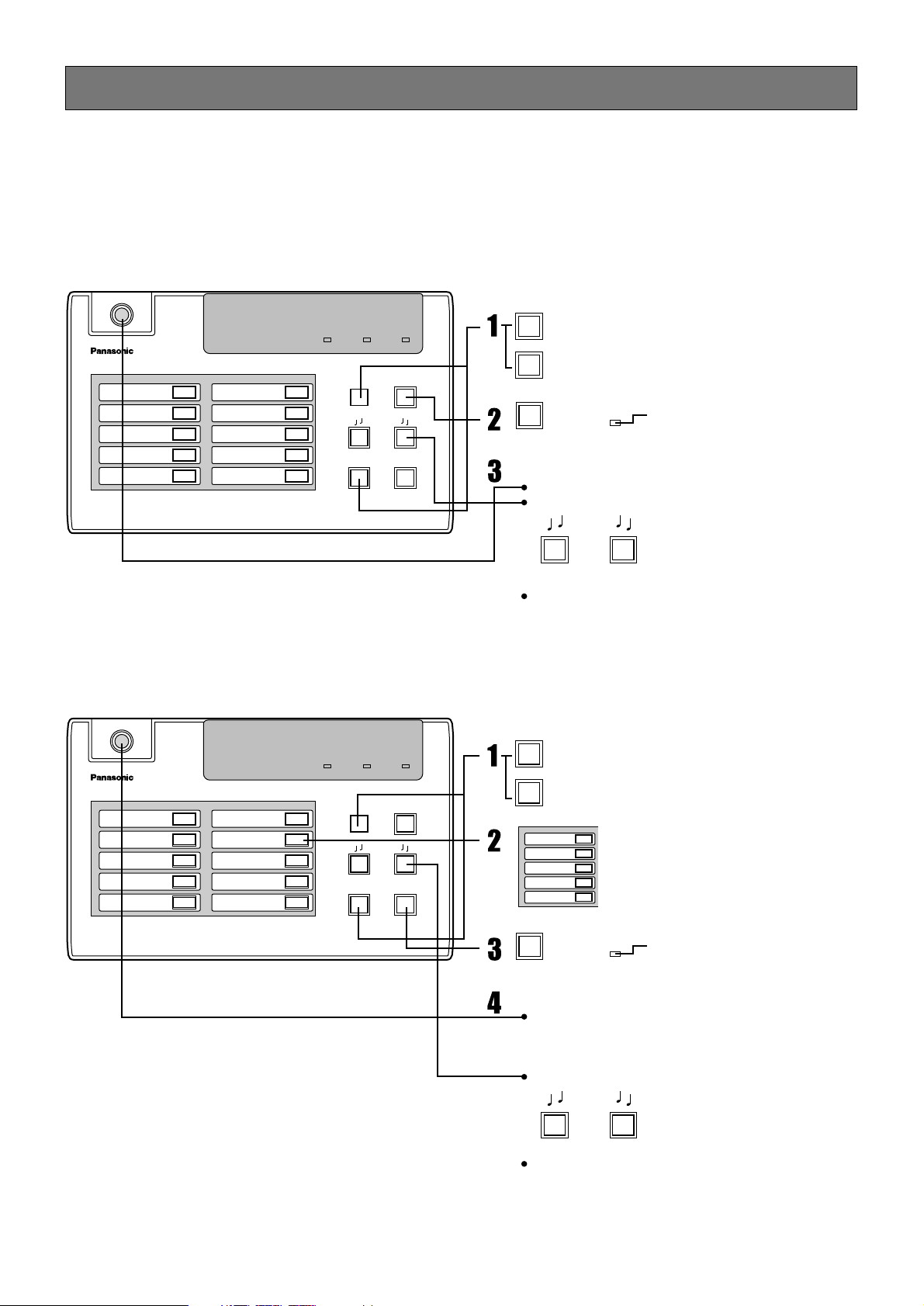
• Write announcement blocks on the supplied name sheets for corresponding individual switches.
• For priority announcement, this unit is not available to make an announcement during the busy indicator lights. Another
remote control microphone is in use.
1
2
3
4
5
MIC
LINE
ALL CALL
MIC
LINE
CALL SIGN
CALL SIGN
ON AIR
Press this button when using the microphone.
Press this button when putting audio from a line
device on the air.
Press the individual switch corres
ponding to your specific block.
Announcement will be canceled by
pressing the switch again.
Press this button when using the microphone.
Press this button when putting audio from a line
device on the air.
Press. On air indicator lighting
Press. On air indicator lighting
An announcement is made through the microphone.
Call sign sounds with this button.
• When the line switch is set to ON, audio from a line device
and audio through the microphone are mixed and put on
the air.
• When the line switch is set to ON, audio from a line device
and audio through the microphone are mixed and put on
the air.
Make an announcement.
An announcement is made through the microphone.
An announcement block can be replaced with another
block by pressing the individual switch for the another
block during announcement.
Call sign sounds with this button.
Make an announcement.
Remote Control Mic WR-210
BUSY
LINE
ON AIR POWER
1
2
3
4
5
6
7
8
9
10
ALL CALL
CALL SIGN
MIC ANNOUNCE
ANNOUNCE
Remote Control Mic WR-210
BUSY
LINE
ON AIR
ON AIR
POWER
1
2
3
4
5
6
7
8
9
10
ALL CALL
CALL SIGN
MIC ANNOUNCE
■ For announcement in unison
■ For individual announcement
Page 7
7
INSTALLATION
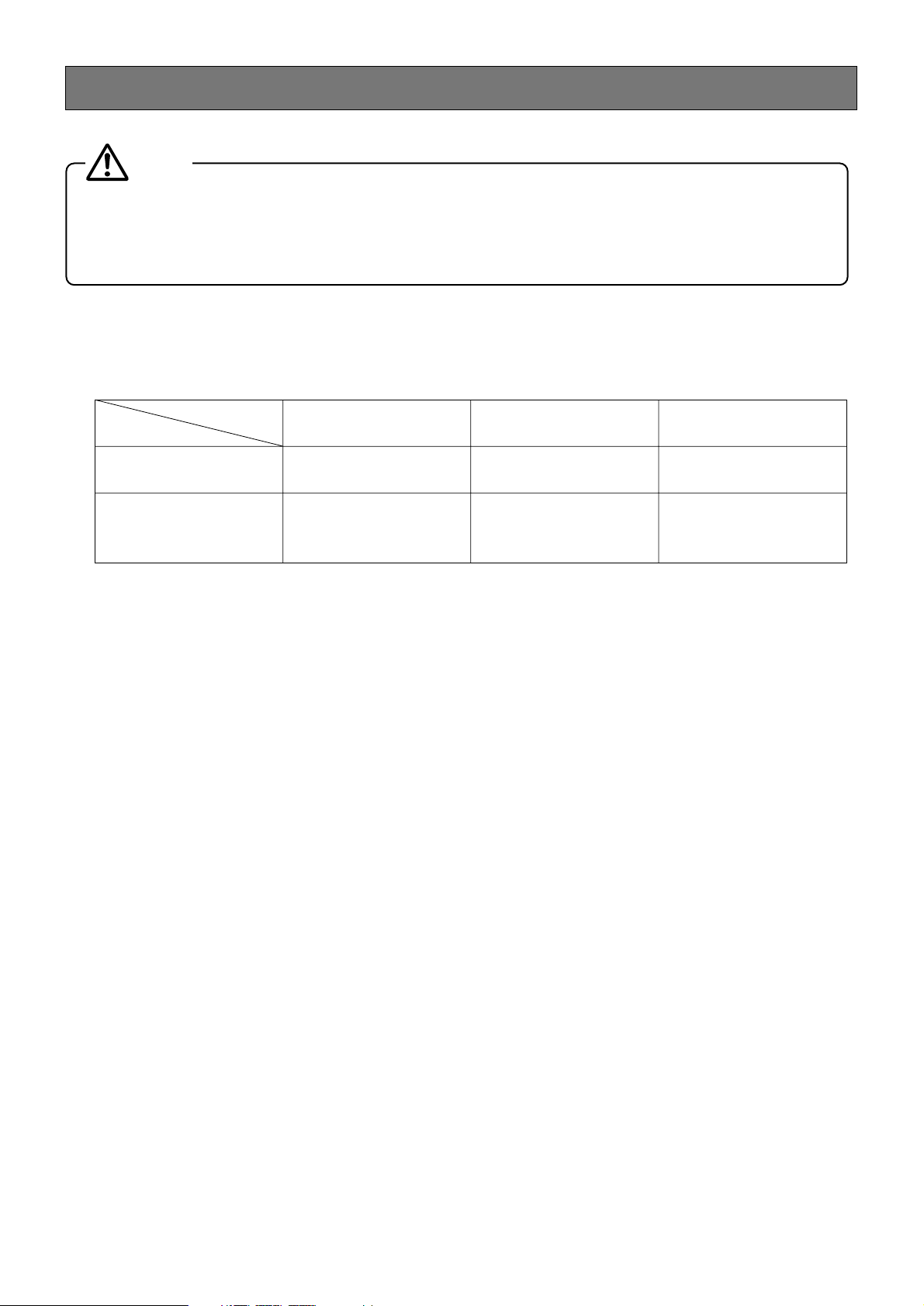
Be sure to place an order with the shop where you purchased this product for installation. Be sure to turn off all the
devices that will be connected to this product and unplug them before installation. Read “PRECAUTION” carefully
and observe its contents.
In addition, read the instructions for the devices to be connected.
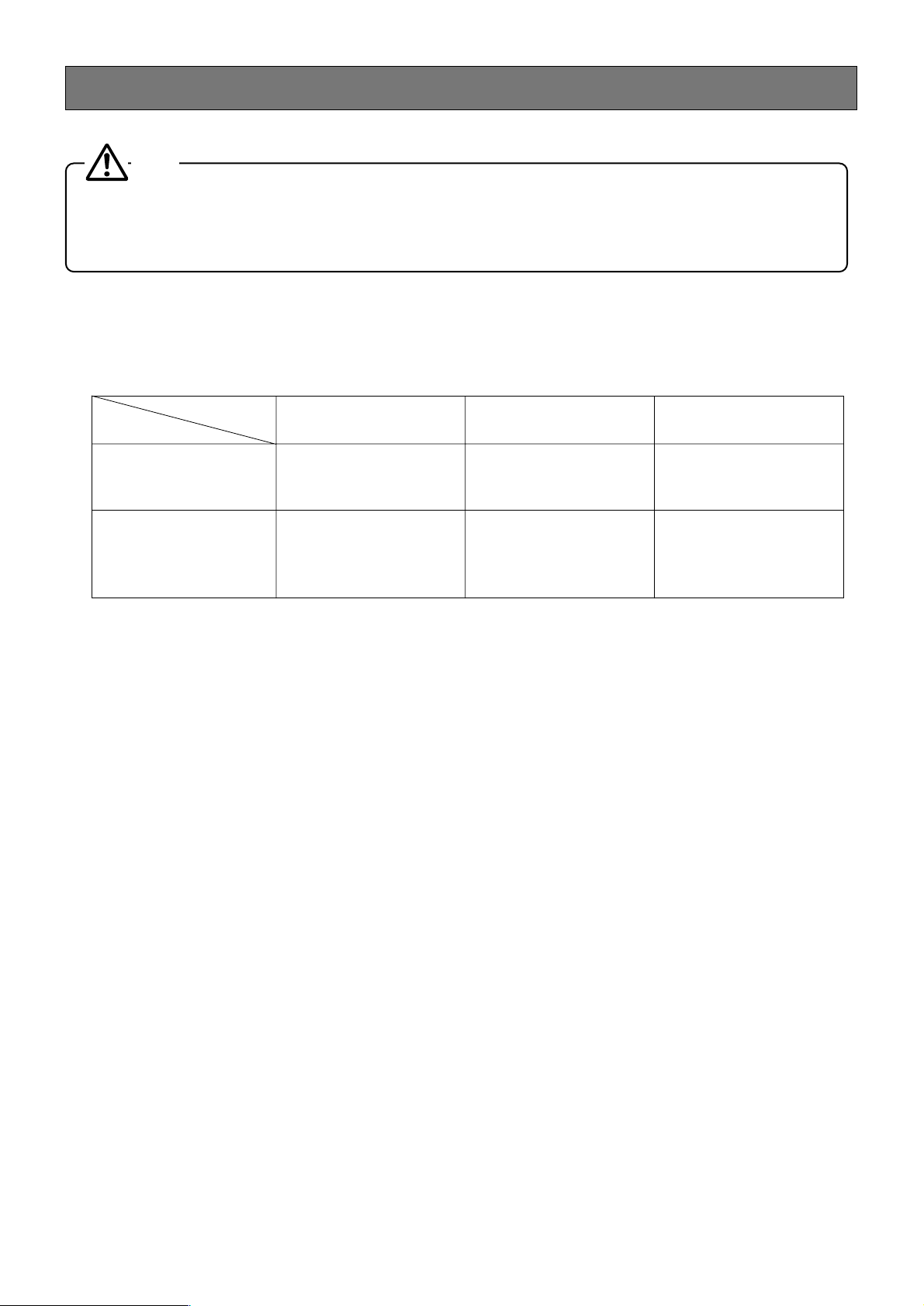
Caution
■ Wire length and diameter
• For use of wire other than the wires shown above, line resistance per one line should be 15 Ω or less.
• For use of the remote control microphone here and there, use stranded wires and splice the wires together.
• See below for the end of the wire.
Standard stripped length: 11 mm
• Applicable wires are described below.
Solid wire: ø0.4 mm (AWG26) to ø1.2 mm (AWG16)
Stranded wire: 0.3 mm
2
(AWG22) to 1.25 mm2(AWG16), strand ø0.18 mm or more
Length
Material
50 m or less 200 m or less 500 m or less
Shielded wire
ø0.4 to ø0.5 mm
(AWG26 to 24
)
ø0.5 mm (AWG24) ø0.5 mm (AWG24)
Control wire
AWG24 to 22
or
ø0.5 to ø1.0 mm
ø0.8 to ø1.2 mm ø1.2 mm
Page 8
8
CABLE CONNECTION
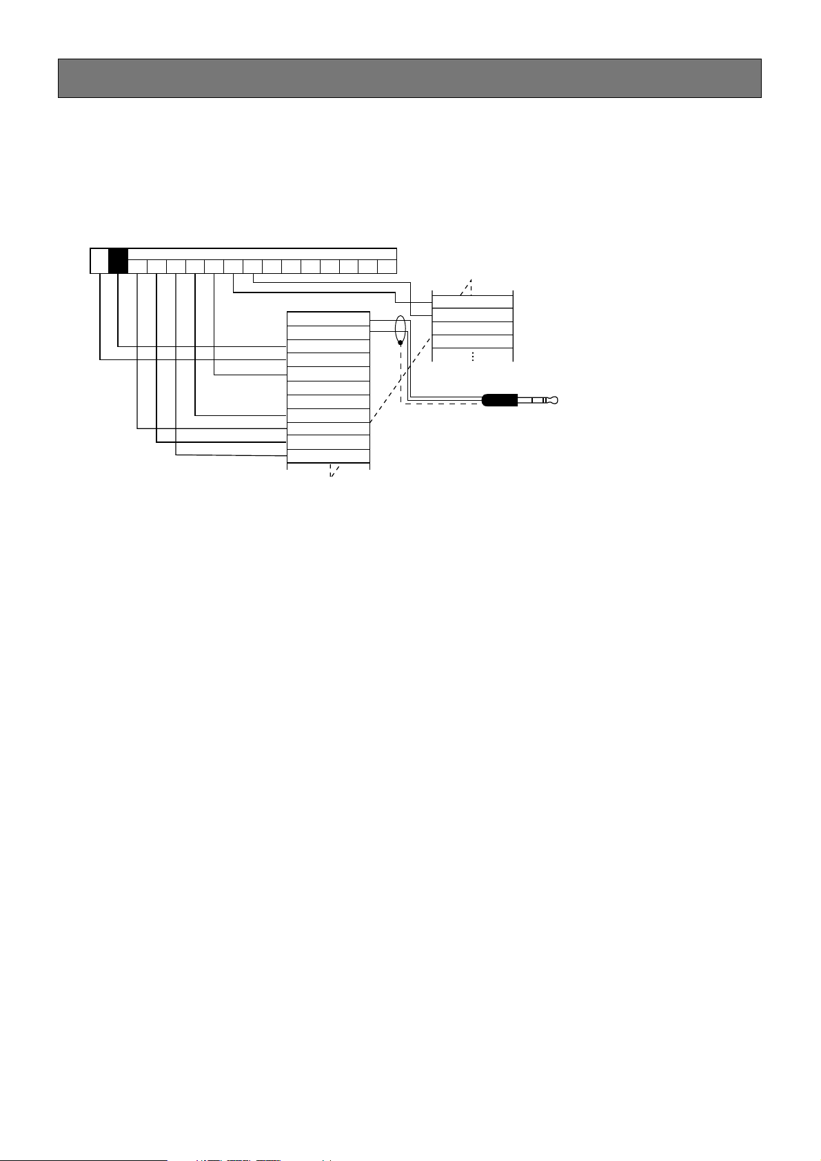
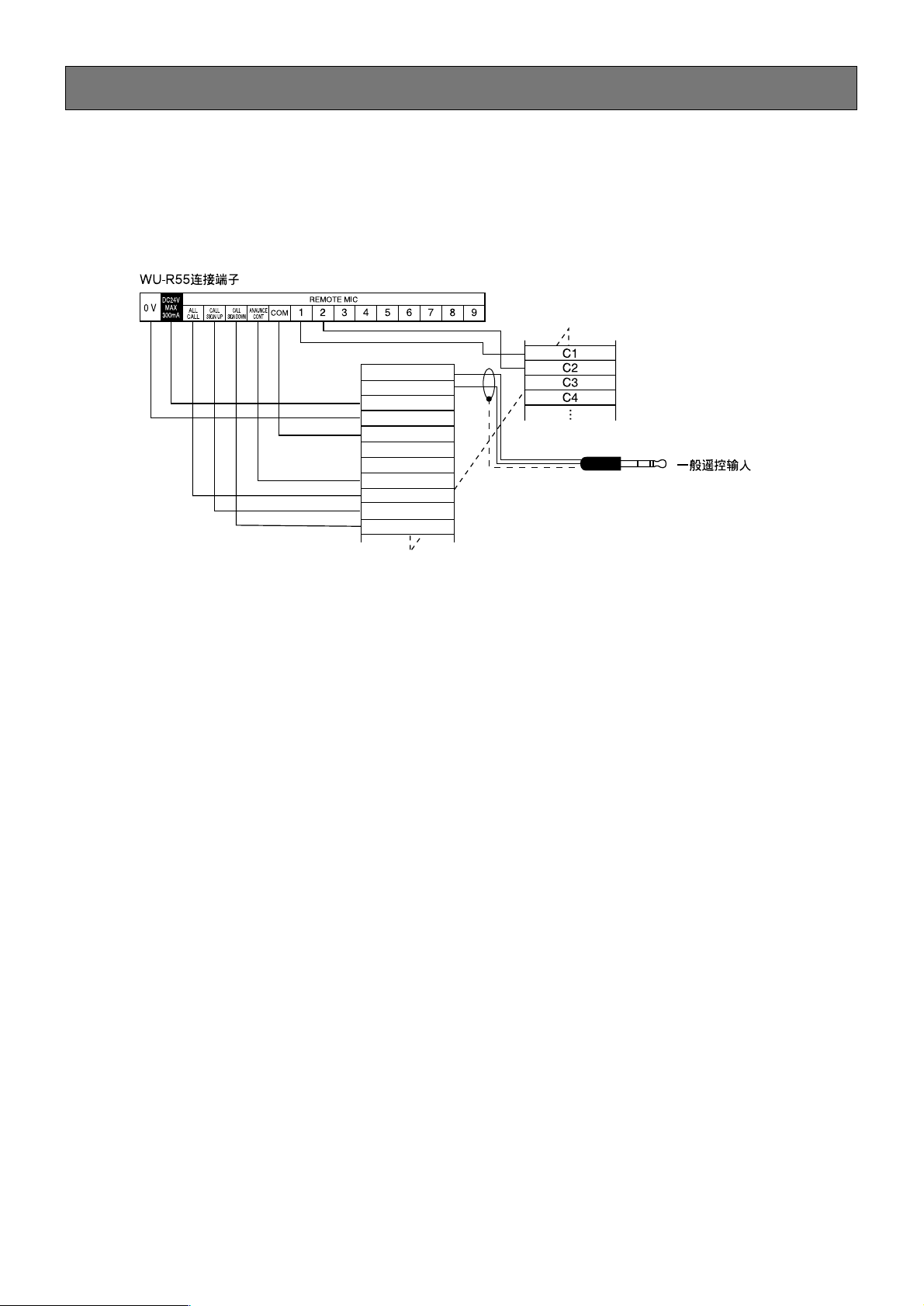
This page explains how to connect this unit to an emergency public address system or a business public address system.
■ Connection to WU-R55
C1
C2
C3
C4
WR-210E
0 V
ALL
CALL
CALL
SIGN UP
CALL
SIGN DOWN
ANAUNCE
CONT
COM
1 2 3 4 5 6 7 8 9
DC24V
MAX
300mA
REMOTE MIC
LINE OUT H
LINE OUT C
DC 24 V
0 V
COM (0 V)
PRIORITY IN
PRIORITY OUT
CONT
CKO
CALL SIGN UP
CALL SIGN DOWN
WU-R55 terminals
To a remote control microphone input
Notes
• The power indicator of the remote control microphone lights up only in the status of announcement.
• For 24 V DC output from WR-210E, make contact between CONT and 0 V, and press an individual switch.
Page 9
9
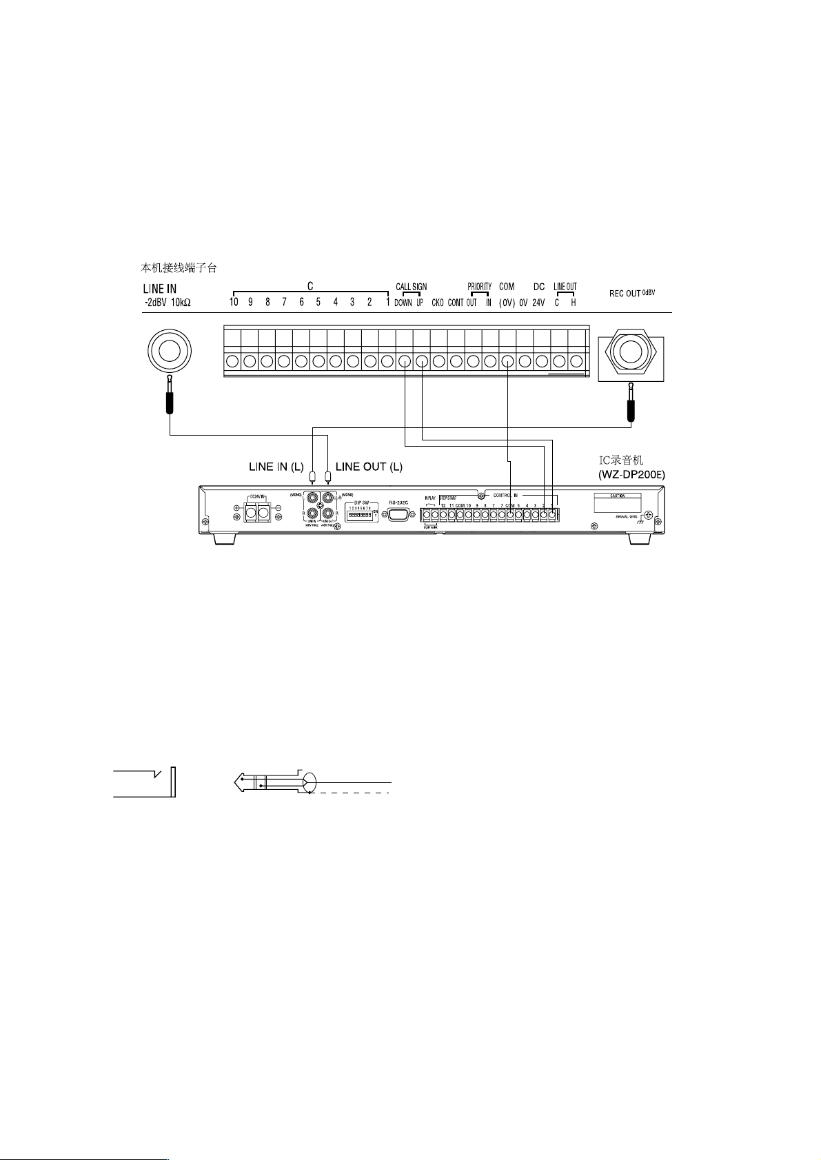
■ Connection to digital IC recorder
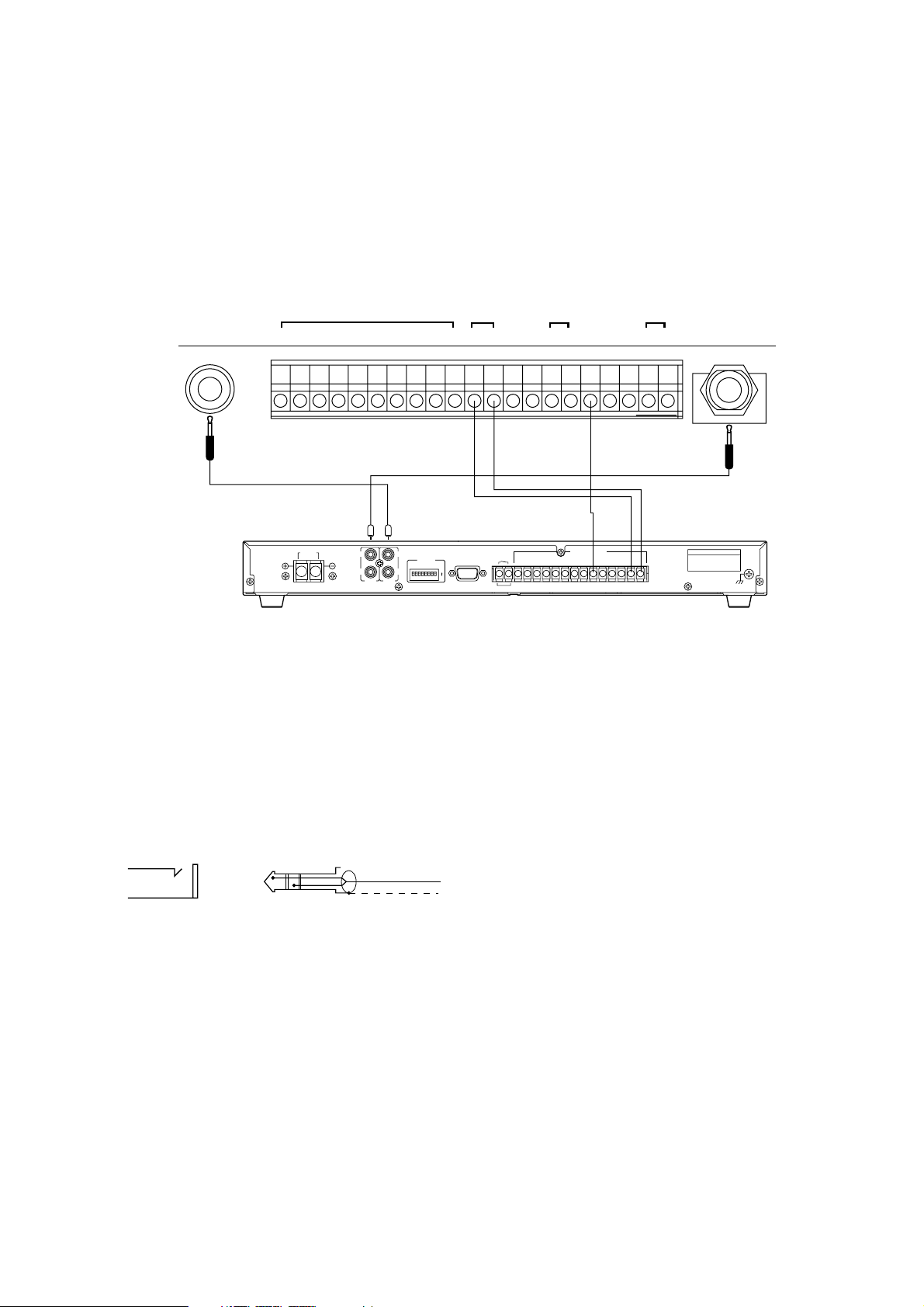
You can enjoy the following after connecting this unit to a digital IC recorder.
• An original call sign recorded on the IC recorder can be on the air by pressing the call sign switch on this unit.
• A program to be announced through the microphone of this unit can be recorded on the IC recorder in advance. The pro-
gram can be on the air by operating the IC recorder. Refer to the operating instructions for the IC recorder to check how to
record or play a program.
REC OUT
Connection terminals
LINE IN
0dBV
-2dBV 10kΩ
COM
C24V0V
CKO CONT
C
21345678910
H
OUT INDOWN
UP (0V)
LINE OUT
DC
PRIORITYCALL SIGN
IC recorder
(WZ-DP200)
LINE IN (L) LINE OUT (L)
SIGNAL GND
CAUTION
12 11 COM 10 9 8 7 7 COM
CONTROL IN
STOP STARTIN PLAY
DIP SW
DC24V IN
ON
12
(MONO)(MONO)
345678
RS-232C
DC24V 1A MAX
54321
LINE IN
0dBV 10KΩ
LINE OUT
+6dBV 10KΩ
RR
L(L+R)
L
■ Connection to line input and record output
• Use a tip-sleeve phone plug usually.
• In case of using a tip-ring-sleeve phone plug, observe the following diagram.
Remote control
microphone side
T (HOT)
R (COLD)
S (GND)
H
C
Page 10
10
PRIORITY ASSIGNMENT
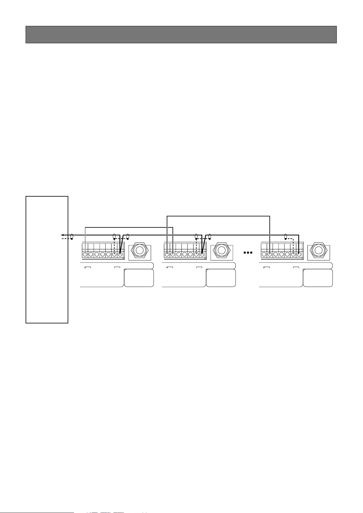
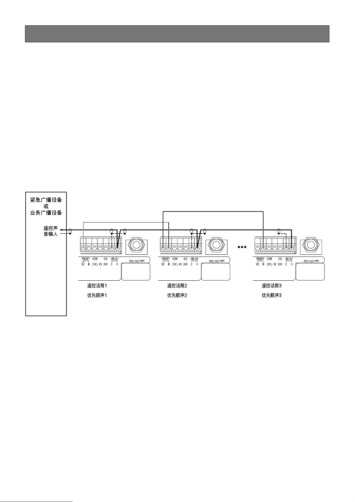
■ Individual priority
Once assigning priorities to remote control microphones, you cannot make an announcement through a lower-priority remote
control microphone during an announcement through a higher-priority remote control microphone.
• How to connect
Connect the priority output of a higher-priority remote control microphone to the priority input of a lower-priority remote
control microphone.
Remote control
microphone 1
1st priority
Remote control
microphone 2
2nd priority
Remote control
microphone n
Nst priority
Emergency public
address system
or
business public
address system
Remote control
audio input
REC OUT
0dBV
COM
C24V0V
H
OUT IN
(0V)
LINE OUT
DC
PRIORITY
REC OUT
0dBV
COM
C24V0V
H
OUT IN
(0V)
LINE OUT
DC
PRIORITY
REC OUT
0dBV
COM
C24V0V
H
OUT IN
(0V)
LINE OUT
DC
PRIORITY
For the use of more than one WR210E, you can assign priorities so that no one can interrupt through lower-priority units when
you are using higher-priority unit.
Individual priority: Priorities are assigned to every remote control microphone. When an announcement starts through a high-
er-priority remote control microphone during an announcement through a lower-priority remote control
microphone, the lower-priority announcement is interrupted.
(Up to 6 units connectable)
■ No priority assigned
• Do not connect the priority input to the priority output.
• Do not make a parallel connection for the audio output line.
Important notices:
• Do not perform the following operation when this unit is connected to a rack type emergency public address system (system controller (WK-850A))or business public address system (system controller (WL-K500)). Failure to observe this may
deactivate this unit and consequently you may not make an announcement.
• Set the announcement switch or all call switch to “OFF” when the power indicator of this unit goes out due to interruption from a higher-priority announcement during the announcement through this unit.
• In case that you cannot make an announcement, press the call sign up and down switches simultaneously. This operation
causes the unit to come into the status of announcement in unison and to be activated. Now, it is ready to be operated.
• Up to 6 remote control microphones can be connected. The number of connected microphones depends on supplied current capacity. (For 6-unit connection, more than 270 mA is required.)
Page 11
5 and 6
5 and 10
The busy indicator lights and
announcement is not available.
The power indicator does not light.
The on air indicator does not light.
• Is the 24 V DC cable connected?
• Is the power switch of the main unit set to “ON”?
• Have you pressed any of the individual switches, the announcement switch and the all call switch?
• Are you making an announcement with the main unit?
5 and 6
Announcement through a microphone is not available.
• Is the microphone switch set to “ON”?
• Have you pressed any of the individual switches, the announcement switch and the all call switch?
Announcement with line input is
not available.
• Is the line switch set to “ON”?
• Have you pressed any of the individual switches, the announce-
ment switch and the all call switch?
5 and 6
• Is there any other microphone in use? If so, you can make an
announcement after the current announcement.
• Is the connection of priority input/output correct?
Symptom Remedy
Ref. page
11
TROUBLESHOOTING
Review the following before asking for repair.
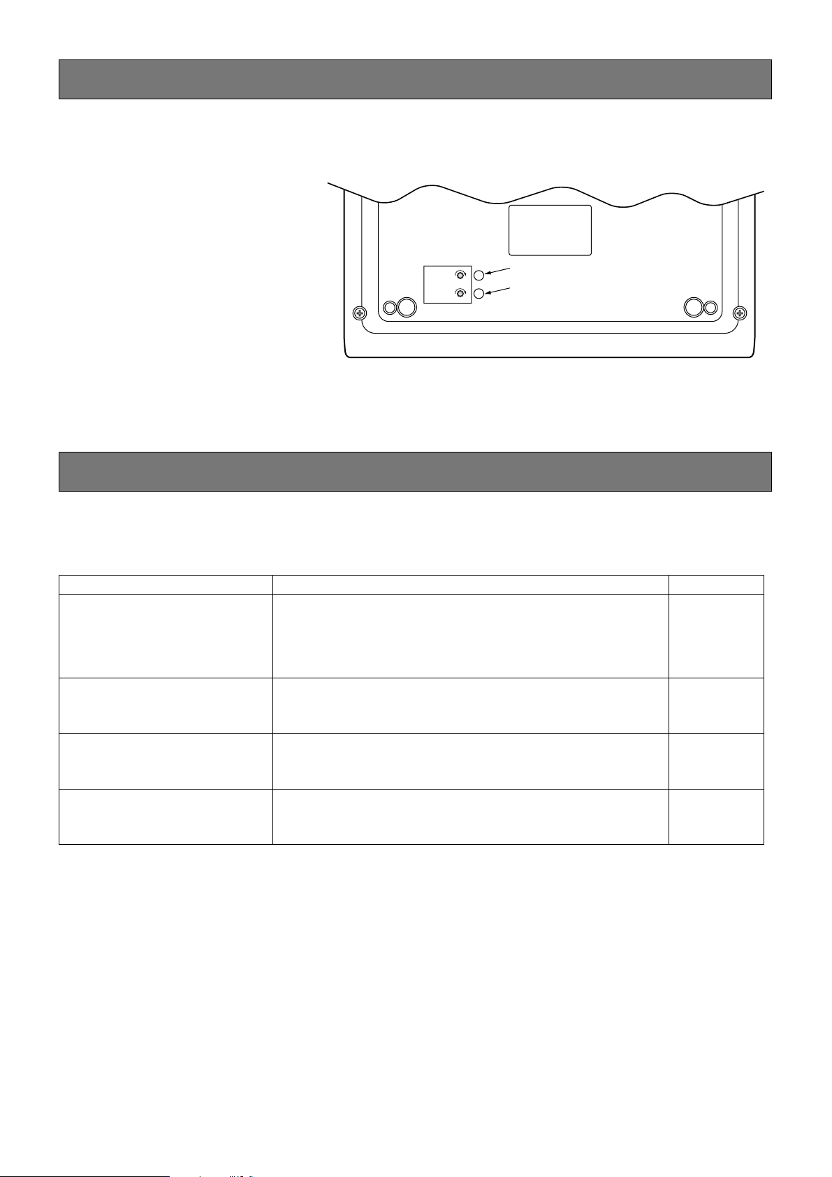
VOLUME ADJUSTMENT
MIC LEVEL
MAX
LINE LEVEL
MAX
Adjusts the volume of the
microphone input.
Adjusts the volume of the line.
Volume adjustment of microphone and line
input is performed with the knobs on the
bottom of the unit. (See the right figure.)
Page 12

12
SPECIFICATIONS
ACCESSORIES
Operating Instructions (this book) .......................................................... 1 pc.
Binding band .......................................................................................... 1 pc.
Windshield .............................................................................................. 1 pc.
Power supply: 24 V DC, 45 mA or less (screwless terminals)
Frequency characteristic: 50-15000 Hz ± 3 dBV (1000 Hz reference) at line input
Distortion factor: 1 % or less (at 1000 Hz)
S/N ratio: 50 dBV or more
Audio input: Flexible microphone: –55 dBV, 600 Ω unbalanced, AGC equipped, one circuit (volume adjust-
ment: semi-fixed)
Business input: –2 dBV, 10 kΩ unbalanced, one circuit (volume adjustment: semi-fixed), large
size tip-sleeve phone jack
Audio output: H, C, 0 dBV, 600 Ω balanced, one circuit, load impedance 300 Ω or more, connection termi-
nals
Record output: 0 dBV, 10 kΩ unbalanced, one circuit, large size tip-sleeve phone jack
Operation switch: Announcement x 1, channel x 10, all call x 1, call sign (up/down) x 2, microphone switch x 1,
line input switch x 1
Display: power, on air, busy
Control output: Announcement control: one circuit, connection terminals, switch output, max. control capacity
30 V DC 50 mA
System control: 1-10 circuits, connection terminals, switch output, max. control capacity 30 V
DC 50 mA
Call sign control up/down: one circuit, connection terminals, switch output, max. control capac-
ity 30 V DC 50 mA
Priority control: priority input, priority output
Microphone: Electret-condenser type (windshield equipped), sensitivity –70 dBV, output impedance 2.2 kΩ,
unidirectional type
Dimensions: 250 (W) x 50 (H) x 155 (D) mm (projections and flexible microphone excluded)
Weight: 700 g
Finishing: Top case: resin, OA ivory coloured (Munsell value 5.5Y7.5/0.3 approximate colour)
Bottom case: resin, grey coloured (Munsell value N5.5 approximate colour)
Page 13
13
中文
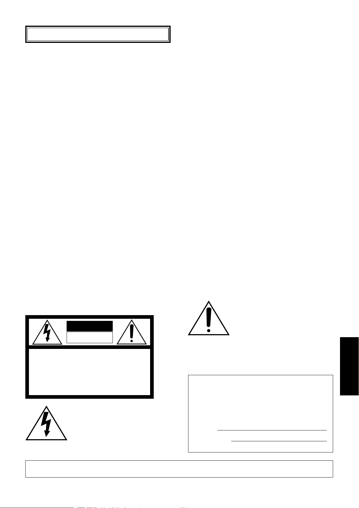
警告:不可让本产品淋雨或受潮,且勿放置盛水容器于产品上,以免水滴溅人,发生火灾或触电。
在正三角形中闪烁的箭头符号,用以
提醒用户在本产品附近出现较大的非
绝缘“危险电压”足以对人体产生触
电。
注意
为了减少触电危险,请勿移动护盖(或
背盖)。内部没有用户能自行修理的零
件。应由有资格的人员进行维修工作。
CAUTION
RISK OF ELECTRIC SHOCK
DO NOT OPEN
在正三角形中的注意号,用以提醒用
户参考有关该机的重要操作与维修的
文字说明。
本产品的制造号码标示于装置的底部。
请在下面空白处填上本机的制造号码,并
将此说明书妥加保存,以便万一遭窃时查
核。
型号:
WR-210E
制造号码:
请注意:
在进行本机的接线或操作之前,请阅读底面的标签。
目录
前 言 ........................................................................................................................................ 14
特 长 ........................................................................................................................................ 14
注意事项 ................................................................................................................................... 14
使用上的注意事项 .................................................................................................................... 15
各部分的名称及其作用 ............................................................................................................ 16
■ 操作部分 ...........................................................................................................................16
■ 背面 .................................................................................................................................. 16
用遥控话筒广播 ....................................................................................................................... 17
■ 同时广播的场合 ............................................................................................................... 17
■ 个别广播的场合 ............................................................................................................... 17
安装说明 ................................................................................................................................... 18
■ 配线距离以及线径 ............................................................................................................ 18
与紧急用广播设备、业务广播系统连接的方法 ....................................................................... 19
■ 与WU-R55连接 ................................................................................................................ 19
■ 与数码IC录音机连接 ....................................................................................................... 20
■ 线路输入,录音输出的连接方法 ..................................................................................... 20
优先顺序的设定 ....................................................................................................................... 21
■ 个别优先 ...........................................................................................................................21
■ 无需设定优先顺序的场合 ................................................................................................ 21
音量的调节 ............................................................................................................................... 22
故障排除 ................................................................................................................................... 22
规 格 ........................................................................................................................................ 23
请确认附属品 ........................................................................................................................... 23
中文
Page 14

14
前言
注意事项
• 将本机与各种音响装置连接后,则可从远距离进
行系统分别广播或同时广播。
• 备有10频道用的WR-210E型。
• 不要试图拆开本设备。为了防止电击,不要取下
螺丝或者机盖。机壳内部没有用户可以自行维修
的部分。所有的维修工作都务必找有资格的维修
人员进行。
• 不要粗暴使用本设备。防止撞击和振动等。不恰
当的搬动和存放可能损坏本设备。务必小心轻放
本设备。
• 清洁机身时不要使用过强的或者有摩擦性的清洁
剂。机身污损时务必使用干布进行清洁。如果污
物难以清除,可用中性清洁剂轻轻擦去。
• 不要将本设备暴露在水和潮湿中,也不要在潮湿
的地方使用本设备。一旦设备沾染潮湿,要立即
采取措施。关断电源并找有资格的维修人员进行
维修。潮湿能够损坏设备,也造成电击的危险。
• 不要在高温和高湿的极端环境中使用本设备。仅
在温度在-10 ℃至+50 ℃范围,湿度低于95 %
的条件下使用本设备。
• 在DC 24 V下工作。
• 安装本产品的每一个必要的步骤都应当由有资格
的维修人员或者系统安装人员进行。
• DC 24 V专用装置。
• 备有录音输出及优先机能。
特长
• 本机为台式机。
• 如将本机的录音输出与IC录音机等连接,则可从
话筒进行声音等简易录音。
• 用话筒开关、线路输入开关可以对声音输入进行
“ON/OFF”控制。
• 用呼号(上升/下降)开关可进行呼号广播(本机与
柜架式紧急广播设备或连接时)。
• 具有个别优先机能。遥控话筒的使用状况可以通
过使用中指示灯及广播中指示灯来进行确认。
Page 15

15
使用上的注意事项
• 本机的优先顺序应从与本机连接的音响装置一侧进行设定。
普通的广播优先顺序一般是下述顺序(紧急广播系统的场合)
1. 特急广播
2. 紧急广播
3. 业务广播 (从遥控话筒等的广播)
• 应在按下广播开关、同时广播开关一秒钟后再进行广播(根据不同的音响装置,有些装置有可能要数秒钟后
才会动作)。
• 有关指示灯
本机的识别及电源和其它的指示灯请参阅本机底面所示。
注意∶碰到操作部分有可能启动广播。所以在清洁保养时应注意不要触摸操作部分,或在适当的状况下进
行清洁保养。
Page 16
16
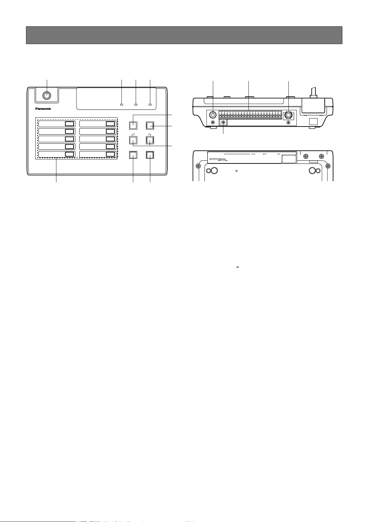
各部分的名称及其作用
q 挠性话筒
可改变话筒的指向。
w 使用中指示灯(BUSY)
其它的遥控话筒广播时此指示灯点亮(连接了优
先功能时)。但是,连接了个别优先设定时优先
顺序低的遥控话筒广播过程中,优先顺序高的遥
控话筒的使用中指示灯不点亮。
e 广播中指示灯(ON AIR)
从本机广播时此指示灯点亮。
r 电源指示灯(POWER)
本机接通了DC24 V电源时此指示灯点亮。
t 线路输入开关(LINE)
广播从线路输入之设备的声音时按下此开关。
y 同时广播开关(ALL CALL)
从本机向所有区域同时广播时按下此开关。同时
广播的时候,不按下广播开关亦可进行广播。
u 呼号开关(TTCALL SIGNTT)
鸣响连接于本机的设备(紧急广播设备或业务广
播设备)的呼号。
注意:请不要同时按下呼号开关。如果同时按下
则成为同时广播状态。
i 广播开关(ANNOUNCE)
从本机广播时按下此开关。如再次按下,则停止
广播。
o 话筒开关(MIC)
从挠性话筒广播时按下此开关。
!0 个别开关(1
10)
仅向特定的区域广播时按下此开关。
!1 线路输入(-2 dBV 10 kΩ非平衡)
用于连接从线路输入设备的声音输出。
!2 连接端子台
用于连接紧急时用广播设备(柜架式,壁挂式)或
业务广播系统等。
!3 录音输出(0 dBV 10 kΩ非平衡)
用于从本机的话筒或从线路输入的音源录音的场
合。
!4 电缆卡
固定连接电缆的束线卡(附属品)时使用。
■ 操作部分
Remote Control Mic WR-210
BUSY
LINE
ON AIR POWER
1
2
3
4
5
6
7
8
9
10
ALL CALL
CALL SIGN
MIC ANNOUNCE
q
wer
t
y
u
io!0
■ 背面
!4
!1 !2 !3
REC OUT
LINE IN
STRIPPING LENGTH 11mm
0dBV
-2dBV 10kΩ
COM
C24V0V
CKO CONT
C
21345678910
11mm
H
OUT INDOWN UP
(0V)
LINE OUT
DC
PRIORITYCALL SIGN
ACCEPTABLE WIRE GAGE
SOLID WIREø0.4 (AWG26)~ø1.2 (AWG16)
STRANDED WIRE0.3mm2~1.25mm2 (AWG16ELEMENT WIREø0.18MIN)
Page 17
17
用遥控话筒广播
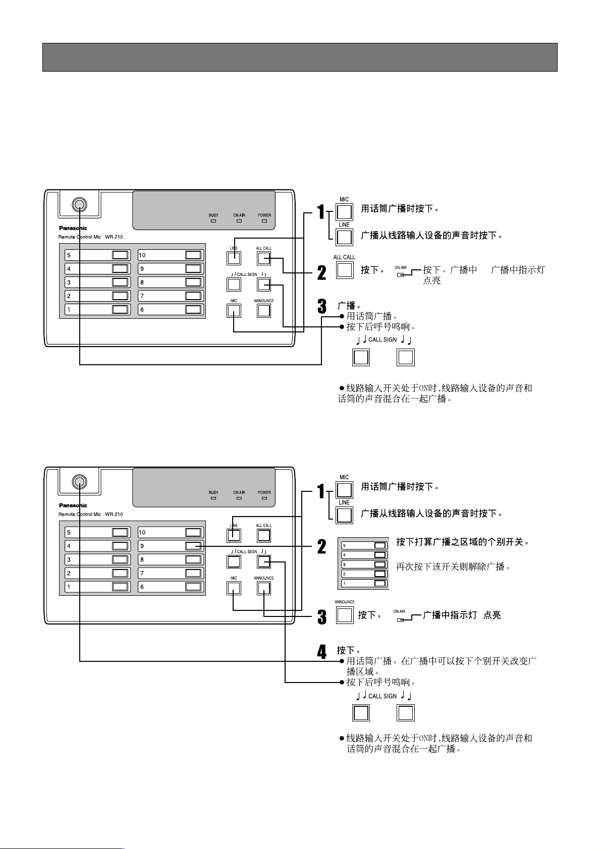
• 先在附属品中的记名标签上写入个别开关的广播区域名。
• 使用中指示灯点亮时,从本机不能广播。意思是正在从其它遥控话筒广播中。(连接了优先功能时)
■ 同时广播的场合
■ 个别广播的场合
Page 18
18
安装说明
务必委托销售商进行安装。安装前,应关断所有连接之设备的电源开关,从电源插座上拔下电源插头。
并认真阅读“安全上的注意事项”,遵从该各种指示。
同时,应配合阅读所连接之设备的使用说明书。
注意
■ 配线距离以及线径
• 使用上述表中以外的线材时,请使用1线的线路电阻在15 Ω
以下的线种。
• 移动遥控话筒使用时,请使用绞线进行中继。
• 连接使用的电缆线的端部均应进行下述处理。
标准剥线长度:11mm
• 可使用的电缆线如下所示
单线:ø0.4 mm(AWG26)~ø1.2 mm(AWG16)
绞线:0.3 mm
2
(AWG22)~1.25 mm2(AWG16),单线径ø0.18 mm以上
距离
线材
50m以下 200 m以下 500 m以下
屏蔽线 ø0.4~ø0.5 mm
(AWG26~24)
ø0.5 mm(AWG24)
ø0.5 mm(AWG24)
控制线 AWG24~22号线
或
ø0.5~ø1.0 mm
ø0.8~ø1.2 mm ø1.2 mm
Page 19
19
与紧急用广播设备、业务广播系统连接的方法
下面简要说明本机与紧急用广播设备或业务广播系统连接的方法。
■ 与WU-R55连接
WR-210E
LINE OUT H
LINE OUT C
DC 24 V
0 V
COM (0 V)
PRIORITY IN
PRIORITY OUT
CONT
CKO
CALL SIGN UP
CALL SIGN DOWN
注意∶
• 遥控话筒的电源指示灯仅在广播状态时点亮。
• 从WR-210E输出DC 24 V时,CONT与0 V作成的同时应按下个别开关。
Page 20
20
■ 与数码IC录音机连接
将本机与数码IC录音机连接,则可进行下述内容的操作。
• 按下本机的呼号开关,可以广播录制在数码IC录音机内的自制呼号。
• 可以在事先将本机从话筒广播的内容录制在数码IC录音机内。然后可以启动IC录音机广播录音的内容。关
于录音及放音的具体方法请阅读数码IC录音机的使用说明书。
■ 线路输入,录音输出的连接方法
• 请使用单头插头连接。
• 使用复式插头时,请按照下图连接。于录音及放音的具体方法请阅读数码IC录音机的使用说明书。
遥控话筒侧
T (HOT)
R (COLD)
S (GND)
H
C
Page 21
21
优先顺序的设定
■ 个别优先
对遥控话筒进行优先顺序设定,优先顺序高的遥控话筒广播的过程中,所有优先顺序低的遥控话筒都不能
广播。
• 连接设定方法
将优先顺序高的遥控话筒的优先输出连接至优先顺序低的遥控话筒的优先输入端。
多台数连接本机的场合,设定优先顺序从优先顺序高的机开始广播时,可设定为从其他机无法广播。
个别优先:按每个遥控话筒的优先顺序设定。当比正在广播中遥控话筒的优先顺序高的遥控话筒开始广播
后,所有优先顺序低的遥控话筒都不能广播。
(最多可连接6台)
■ 无需设定优先顺序的场合
• 优先输入及优先输出均不连接。
• 声音输出连线不作并联连接。
重要
• 将本机连接于柜架型紧急广播设备(系统控制器(WK-850A))或业务广播设备(系统控制器(WL-K500))的场
合,请勿进行下述操作。否则可能导致本机电源无法接通以致无法广播。
• 用本机广播的过程中,插入比本机广播优先顺序高的广播而本机电源指示灯熄灭时,广播开关及同时广
播开关均为“断开”状态。
• 无法广播时,请同时按下上升和下降的呼号开关。
则可成为同时广播状态,并且本机电源接通。其后则正常动作。
• 遥控的最多连接台数为6台。根据所连接之系统的电源容量,限制可连接的台数(连接6 台时,需要270
mA以上的电流)。
Page 22
现象
16页
17页
16页
17页
·线路输入的开关是否为“ON”?
·个别开关,广播开关或同时广播开关是否忘记按下?
22
故障排除
16页,21页正在广播指示灯点亮,
但不能广播
电源指示灯不亮
正在广播指示灯不亮
对策方法
请在送出修理之前,再次检查下述各有关事项。
参阅页
·DC 24 V电缆是否连接?
·本机的电源是否为“ON”?
·个别开关,广播开关或同时广播开关是否忘记按下?
·本机一侧是否有广播?
16页
17页
话筒不能广播 ·话筒的开关是否为“ON”?
·个别开关,广播开关或同时广播开关是否忘记按下?
线路输入不能广播
·是否其他遥控话筒在广播中? 该广播结束后即可使用。
·优先输入/输出的电缆连接是否有误?
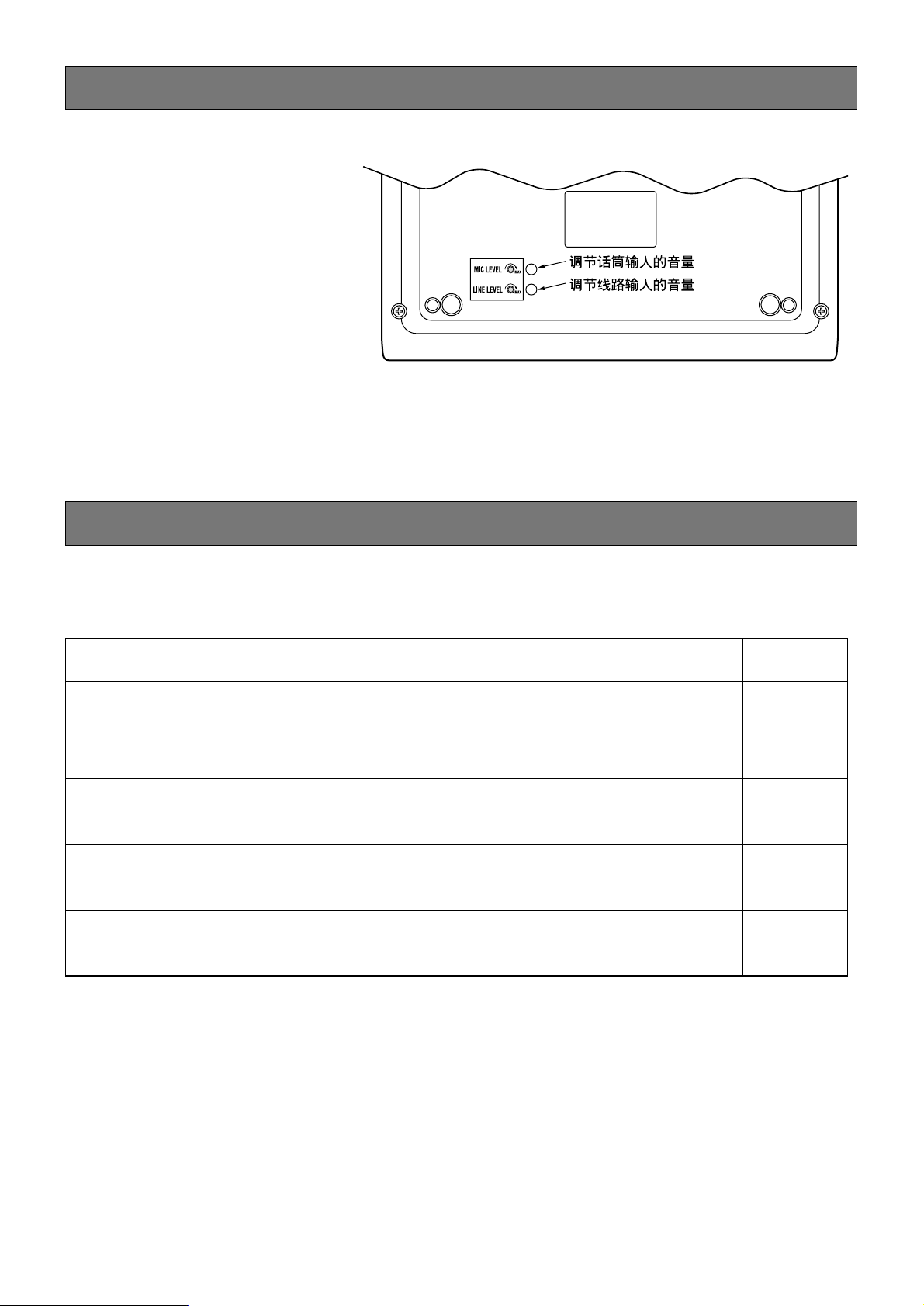
音量的调节
话筒及线路输入的音量均用本机底面
的电位器进行调节(参阅右图)。
Page 23

23
规格
请确认附属品
使用说明书(此书) ............................................... 1
束线卡 ................................................................ 1
防风外罩 .............................................................. 1
电源∶ DC 24 V,45 mA以下(无螺丝端子台)
频率特性∶ 50~15000 Hz±3 dBV(1000 Hz基准)线路输入时
失真率∶ 1 %以下(1000 Hz时)
信噪比∶ 50 dBV以上
声音输入∶ 挠性话筒∶-55 dBV,600 Ω非平衡,带有AGC,
1电路(音量调节∶半固定电位器)
业务输入∶-2 dBV,10 kΩ非平衡,1电路(音量调节∶半固定电位器)
大单孔插座
声音输出∶ H,C,0dBV,600 Ω平衡,1电路,负荷阻抗300 Ω以上∶接线端子台
录音输出∶0 dBV,10 kΩ 非平衡,1电路,大单孔插座
操作开关∶ 广播×1,选频道×10,同时广播×1,呼号(上升/下降)×2,
话筒开关,线路输入开关×各1
指示灯∶ 电源,广播中,使用中
控制输出∶ 广播控制∶1电路,连接端子台,开关输出,最大控制容量DC 30 V,50 mA
系统控制∶1~10电路,连接端子台,开关输出,
最大控制容量DC 30 V,50 mA
呼号控制上升·下降∶1电路,连接端子台
开关输出,最大控制容量DC 30 V,50 mA
优先控制∶优先输入,优先输出
话筒∶ 电子电容型(防风型),灵敏度-70 dBV,输出阻抗2.2 kΩ单一指向性
尺寸∶ 250 mm(宽)×50 mm(高)×155 mm(厚) (不包括凸起及挠性话筒部分)
重量∶ 700g
外壳∶ 上外壳∶树脂OA象牙白色(蒙塞尔5.5Y7.5/0.3近似色)
下外壳∶树脂,灰色(蒙塞尔N5.5近似色)
Page 24

NM0603-0 3TR001766AAA 在日本印刷
2003 © Matsushita Electric Industrial Co., Ltd. All rights reserved.
Printed in Japan
 Loading...