

Panasonic WJ-SX650P User Manual
Matrix Switcher WJ-SX
650
OPERATE
OPERATE LED WILL BLINK
IF COLLING FAN MALFUNCTIONS
Matrix Switcher
Operating Instructions
Model Nos. WJ-SX650 Series
Before attempting to connect or operate this product,
please read these instructions carefully and save this manual for future use.
CAUTION
RISK OF ELECTRIC SHOCK
DO NOT OPEN
For Canada
This Class A digital apparatus complies with Canadian
ICES-003.
CAUTION: TO REDUCE THE RISK OF ELECTRIC SHOCK,
DO NOT REMOVE COVER (OR BACK).
NO USER-SERVICEABLE PARTS INSIDE.
REFER SERVICING TO QUALIFIED SERVICE PERSONNEL.
The lightning flash with arrowhead symbol,
within an equilateral triangle, is intended to
alert the user to the presence of uninsulated
"dangerous voltage" within the product's
enclosure that may be of sufficient magni-
SA 1965
SA 1966
tude to constitute a risk of electric shock to
persons.
The exclamation point within an equilateral
triangle is intended to alert the user to the
presence of important operating and maintenance (servicing) instructions in the literature accompanying the appliance.
Power disconnection. Unit with or without
ON-OFF switches have power supplied to
the unit whenever the power cord is inserted
into the power source; however, the unit is
operational only when the ON-OFF switch is
in the ON position. The power cord is the
main power disconnect for all units.
For U.S.A
NOTE: This equipment has been tested and found to comply with the limits for a Class A digital device, pursuant to
Part 15 of the FCC Rules. These limits are designed to provide reasonable protection against harmful interference
when the equipment is operated in a commercial environment. This equipment generates, uses, and can radiate
radio frequency energy and, if not installed and used in
accordance with the instruction manual, may cause harmful
interference to radio communications.
Operation of this equipment in a residential area is likely to
cause harmful interference in which case the user will be
required to correct the interference at his own expense.
FCC Caution: To assure continued compliance, (example use only shielded interface cables when connecting to computer or peripheral devices). Any changes or modifications
not expressly approved by the party responsible for compliance could void the user’s authority to operate this equipment.
The serial number of this product may be found on the surface of the unit.
You should note the serial number of this unit in the space
provided and retain this book as a permanent record of your
purchase to aid identification in the event of theft.
Model No.
Serial No.
WARNING:
• This apparatus must be earthed.
• Apparatus shall be connected to a mains socket outlet with a protective earthing connection.
• The mains plug or an appliance coupler shall remain readily operable.
• To prevent fire or electric shock hazard, do not expose this apparatus to rain or moisture.
• The apparatus should not be exposed to dripping or splashing and that no objects filled with liquids, such as vases, should be
placed on the apparatus.
• All work related to the installation of this product should be made by qualified service personnel or system installers.
• The connections should comply with local electrical code.
2

Important Safety Instructions
1) Read these instructions.
2) Keep these instructions.
3) Heed all warnings.
4) Follow all instructions.
5) Do not use this apparatus near water.
6) Clean only with dry cloth.
7) Do not block any ventilation openings. Install in accordance with the manufacturer's instructions.
8) Do not install near any heat sources such as radiators, heat registers, stoves, or other apparatus (including amplifiers) that
produce heat.
9) Do not defeat the safety purpose of the polarized or grounding-type plug. A polarized plug has two blades with one wider
than the other. A grounding type plug has two blades and a third grounding prong. The wide blade or the third prong are
provided for your safety. If the provided plug does not fit into your outlet, consult an electrician for replacement of the
obsolete outlet.
10) Protect the power cord from being walked on or pinched particularly at plugs, convenience receptacles, and the point
where they exit from the apparatus.
11) Only use attachments/accessories specified by the manufacturer.
12) Use only with the cart, stand, tripod, bracket, or table specified by the manufacturer, or sold with the apparatus. When a
cart is used, use caution when moving the cart/apparatus combination to avoid injury from tip-over.
S3125A
13) Unplug this apparatus during lightning storms or when unused for long periods of time.
14) Refer all servicing to qualified service personnel. Servicing is required when the apparatus has been damaged in any way,
such as power-supply cord or plug is damaged, liquid has been spilled or objects have fallen into the apparatus, the
apparatus has been exposed to rain or moisture, does not operate normally, or has been dropped.
3

CONTENTS
Important Safety Instructions ............................................ 3
Limitation of Liability ........................................................... 5
Disclaimer of Warranty ....................................................... 5
Trademarks and Registered Trademarks ........................... 5
Precautions ......................................................................... 6
About These Operating Instructions ................................... 7
Preface ............................................................................... 8
Features .............................................................................. 8
Major Operating Controls and Their Functions ................... 9
■ WJ-SX650 Matrix Switcher/
WJ-SX650U Card Cage ................................................ 9
■ Video Input Board WJ-PB65C32 ................................ 11
■ Video Output Board WJ-PB65M16 ............................. 12
■ Monitor Display Information ........................................ 13
■ System Controller Display Information ....................... 14
Installations ....................................................................... 16
■ Checking Board Composition ..................................... 16
■ Switch Settings for Video Input Main Board ............... 17
■ Switch Settings for Video Output Main Board ............. 18
■ Mounting Video Input and Output Boards ................... 19
■ Board Mounting Procedure ......................................... 20
■ Installing the Main Unit ............................................... 21
Connections ...................................................................... 22
■ Basic System Connections ......................................... 23
■ Expanded System Connections .................................. 24
■ Card Cage Connections ............................................. 26
■ Camera Connections .................................................. 27
■ RS-485 Camera Connections ..................................... 27
■ Monitor Connections ................................................... 29
■ PC Connection ............................................................ 29
■ Recorder Connection .................................................. 30
■ Recorder Settings ....................................................... 34
■ System Controller Connection .................................... 34
■ Alarm Sensor Connections ......................................... 36
■ External Device Connections ...................................... 36
■ System Status Check ................................................. 37
Setup Procedure ............................................................... 38
WJ-SX650 Series Administrator Console ......................... 40
■ System Requirements of a PC ................................... 40
■ Installation and Uninstallation ..................................... 40
■ Starting Up .................................................................. 41
■ Window Details ........................................................... 41
■ Tooltip Details ............................................................. 42
Factory Default Settings ................................................... 45
■ Factory Default Settings of WJ-SX650 Series
Administrator Console ................................................ 45
■ Factory Default Settings of SETUP MENU ................. 47
Setup Menu (OSD) ........................................................... 48
■ Basic Operations ........................................................ 48
■ TIME & DATE ............................................................. 49
■ ALARM ....................................................................... 49
■ RECORDER ............................................................... 50
■ SYSTEM ..................................................................... 52
■ INFORMATION ........................................................... 54
■ LANGUAGE ................................................................ 54
Login and Logout .............................................................. 55
■ Operator Registration ................................................ 55
■ Power-on/off ............................................................... 56
■ Operation Start (Login) ............................................... 56
■ Operation End (Logout) .............................................. 56
■ Operation Start/End (Auto Login/Logout) ................... 56
Monitor Control ................................................................. 57
■ Monitor Selection ........................................................ 57
■ Monitor Lock ............................................................... 57
Camera Control ................................................................ 58
■ Camera Selection ....................................................... 58
■ Camera Selection Recall ............................................ 58
■ Preset Position Control ............................................... 58
■ All Cameras Control .................................................... 59
Recorder Control .............................................................. 60
■ Playback ..................................................................... 60
■ Manual Recording ....................................................... 60
■ Multiscreen Display ..................................................... 60
■ Search Playback ......................................................... 60
■ Playing the Latest Recorded Image ............................ 60
■ Recorder Control End ................................................. 61
■ Recorder Selection ..................................................... 61
Running Sequence ........................................................... 62
■ Descriptions of Sequence ........................................... 62
■ Tour Sequence ........................................................... 64
■ Group Sequence/Preset ............................................. 64
■ Sequence Pause ........................................................ 65
■ Sequence Stop ........................................................... 65
Alarm Descriptions ............................................................ 66
■ Alarm Occurrence ....................................................... 66
■ Alarm Modes ............................................................... 67
■ Video Loss .................................................................. 67
Alarm Control .................................................................... 68
■ Alarm Acknowledgement (ACK) ................................. 68
■ Camera Control .......................................................... 68
■ Alarm Picture Change ................................................. 68
■ Alarm Individual Reset ................................................ 68
■ Alarm Monitor Reset ................................................... 68
■ Alarm All Reset ........................................................... 68
■ Return to Alarm Mode Status ..................................... 69
■ Alarm Suspension ....................................................... 69
■ Alarm History Display ................................................. 69
Timer Descriptions ............................................................ 71
■ Timer Event ................................................................ 71
■ Camera Event ............................................................. 71
Terminal Mode Operation ................................................. 73
■ Lists of Operations and Functions .............................. 73
■ Menu Flow (WV-CU950/650) ...................................... 84
Operation (Other than Terminal Mode) ............................. 85
■ PS·Data Mode Operations .......................................... 85
■ Connections of Matrix Switchers (WJ-SX650 Series)
and a PS·Data System Controller ............................... 86
■
Controlling from a Web Browser Accessing a Recorder .....86
■ Controlling from a PC ................................................. 86
Glossary ............................................................................ 87
Troubleshooting ................................................................ 89
■ Matrix Switcher WJ-SX650 Series............................... 89
■ WJ-SX650 Series Administrator Console .................... 93
■ Power Cord, Connectors, and Power Plug ................. 94
Specifications .................................................................... 95
■ Matrix Switcher WJ-SX650 Series................................95
■ Card Cage WJ-SX650U................................................96
■ Video Input Board WJ-PB65C32 ..................................96
■ Video Output Board WJ-PB65M16 ...............................96
■ Expansion Cable Kit WJ-CA65L20K/WJ-CA65L07K....97
■ D-sub/BNC Video Cable WJ-CA68...............................97
Standard Accessories ....................................................... 97
4

Limitation of Liability
THIS PUBLICATION IS PROVIDED "AS IS" WITHOUT WARRANTY OF ANY KIND, EITHER EXPRESS OR IMPLIED,
INCLUDING BUT NOT LIMITED TO, THE IMPLIED WARRANTIES OF MERCHANTABILITY, FITNESS FOR ANY PARTICULAR PURPOSE, OR NON-INFRINGEMENT OF THE
THIRD PARTY’S RIGHT.
Disclaimer of Warranty
IN NO EVENT SHALL MATSUSHITA ELECTRIC INDUSTRIAL CO., LTD. BE LIABLE TO ANY PARTY OR ANY PERSON, EXCEPT FOR CERTAIN WARRANTY PROGRAM
OFFERED BY THE LOCAL DEALER OF PANASONIC, FOR
THE CASES INCLUDING BUT NOT LIMITED TO BELOW:
(1) ANY DAMAGE AND LOSS, INCLUDING WITHOUT LIM-
ITATION, DIRECT OR INDIRECT, SPECIAL, CONSEQUENTIAL OR EXEMPLARY, ARISING OUT OF OR
RELATING TO THE PRODUCT;
(2) PERSONAL INJURY OR ANY DAMAGE CAUSED BY
INAPPROPRIATE USE OR NEGLIGENT OPERATION
OF THE USER;
THIS PUBLICATION COULD INCLUDE TECHNICAL INACCURACIES OR TYPOGRAPHICAL ERRORS. CHANGES
ARE ADDED TO THE INFORMATION HEREIN, AT ANY
TIME, FOR THE IMPROVEMENTS OF THIS PUBLICATION
AND/OR THE CORRESPONDING PRODUCT (S).
(3) UNAUTHORIZED DISASSEMBLY, REPAIR OR MODIFI-
CATION OF THE PRODUCT BY THE USER;
(4) INCONVENIENCE OR ANY LOSS ARISING WHEN
IMAGES ARE NOT DISPLAYED, DUE TO ANY REASON
OR CAUSE INCLUDING ANY FAILURE OR PROBLEM
OF THE PRODUCT;
(5) ANY PROBLEM, CONSEQUENTIAL INCONVENIENCE,
OR LOSS OR DAMAGE, ARISING OUT OF THE SYSTEM COMBINED BY THE DEVICES OF THIRD PARTY;
Trademarks and Registered Trademarks
• Microsoft, Windows and Windows XP are registered
trademarks of Microsoft Corporation in the U.S. and/or
other countries.
• Intel and Pentium are registered trademarks of Intel
Corporation or its subsidiaries in the United States and
other countries.
• Other company names and product names appearing
in this document are registered trademarks or trademarks of the company concerned.
5

Precautions
CAUTION: These servicing instructions are for use by qual-
ified service personnel only. To reduce the risk of electric shock do not perform any servicing other than that
contained in the operating instructions unless you are
qualified to do so.
• Do not block the ventilation opening or slots on the
cover.
To prevent the apparatus from overheating, place it at
least 5 cm {2 inches} away from the wall.
• Do not drop metallic parts through slots.
This could permanently damage the apparatus. Turn
the power off immediately and contact qualified service
personnel for service.
• Do not attempt to disassemble the apparatus.
To prevent electric shock, do not remove screws or
covers.
There are no user-serviceable parts inside. Contact
qualified service personnel for maintenance.
• Do not strike or give a strong shock to the unit.
It may cause damage or allow water to enter the unit.
• Do not expose the apparatus to water or moisture.
Do not try to operate it in wet areas.
Take immediate action if the apparatus gets wet. Turn
the power off and refer servicing to qualified service
personnel. Moisture can damage the apparatus and
also cause electric shocks.
• Built-in backup battery
Before the first use, charge the built-in backup battery
(lithium battery) by turning on the power for 48 hours or
more. If it is not charged enough, in a case where the
power goes down, the internal clock may keep bad
time or the operative condition may be different to that
before the electric power failure.
The built-in battery life is approximately 5 years as an
indication of replacement. (This is just an indication of
replacement. We are not providing any guarantee of the
built-in battery lifetime. Replacement cost of the built-in
battery is not covered by the warranty even if it needs
to be done within the warranty period.) Ask the shop
where you purchased the unit when replacement of the
battery is required.
• Cooling Fan
Turn the power off when cleaning the unit. Otherwise it
may cause injuries.
The cooling fan will operate for approximately 30 000
hours. Replacement costs of the cooling fan are not
covered by the warranty even if it needs to be done
within the warranty period.
• Cleaning
Turn the power off when cleaning the unit. Otherwise it
may cause injuries.
Do not use strong or abrasive detergents when cleaning the apparatus body.
Use a dry cloth to clean the apparatus when it is dirty.
When the dirt is hard to remove, use a mild detergent
and wipe gently.
• Do not operate the apparatus beyond its specified
temperature, humidity, or power source ratings.
Use the apparatus under conditions where temperatures are between –10 °C and + 50 °C {14 °F to 122 °F},
and humidity below 90 %.
The apparatus may not work properly after turning on in
a cold atmosphere between –10 °C and 0 °C {14 °F to
32 °F}. Wait approximately 10 minutes until the inside
temperature has risen to 0 °C {32 °F}, it can work properly.
The input power source for this apparatus is 120 V AC,
60 Hz.
• Place the unit horizontally on a level surface. Do not
place the unit in an upright position. When stacking
multiple units, clear a space of more than 5 cm {2
inches} from both sides, the top, the bottom and the
rear of the units.
• Pay attention to static electricity
Make certain to keep boards inside the anti-static sack
until it is installed.
Put your hand on a metallic surface, other than the
boards to discharge static electricity before installation.
Do not touch components mounted on the boards
directly by hand.
Hold only both edges of the boards when installing.
• Do not use any power cord other than the one supplied.
• Only use the apparatus indoors.
Do not install it in places where the apparatus is
exposed to sunlight for long periods of time or near air
conditioning equipment. This will cause deformation,
discoloration, breakdown or malfunction.
• We recommend that you make a note of your settings and save them. This will help when you are
required to change the system configuration, or
when unexpected trouble or failure occurs.
• Distributing, copying, disassembling, reverse compiling, reverse engineering, and also exporting in
violation of export laws of the software provided
with this product, is expressly prohibited.
6

About These Operating Instructions
These operating instructions are classified roughly as follows:
• Operations (pp. 55 to 86)
Contains how to operate the system. These descriptions are intended for operators.
Note: Before operation, be sure to read safety instruc-
tions on p. 3 IMPORTANT SAFETY INSTRUCTIONS
and p. 6 PRECAUTIONS.
• Preparations (pp. 16 to 54)
Contains the required preparations including installation, connections, and setup procedures. These
descriptions are intended for installers and system
administrators.
Classification of digital disk recorders are as follows.
Term
WJ-HD300 Series
Model Nos.
WJ-HD316, WJ-HD309
This document uses the following terms for classification of devices.
The (This ) unit: Matrix Switcher WJ-SX650
Video input board: Video Input Board WJ-PB65C32
Video output board: Video Output Board WJ-PB65M16
Recorder: Digital Disk Recorder WJ-HD300/WJ-HD300
A Series
Remarks on Model Nos.
Begins with "WJ-HD316".
WJ-HD300A Series
WJ-HD316A, WJ-HD309A
Begins with "WJ-HD316A".
7

Preface
Matrix Switcher WJ-SX650 Series (or SX650 Series) are
designed for a surveillance control system. WJ-SX650
Series (or SX650 Series) is the general term of following
models.
Matrix Switcher WJ-SX650 (Video Input Board WJPB65C32 x 1 and Video Output Board WJ-PB65M16 x 1
have been installed.)
Card Cage WJ-SX650U (For additional installation of video
input boards and video output boards)
Video Input Board WJ-PB65C32
Video Output Board WJ-PB65M16
Expansion Cable Kit WJ-CA65L20K/WJ-CA65L07K
D-sub/BNC Video Cable WJ-CA68
Features
• Up to 256 cameras, 32 monitors connectable
• Remote control of optional external devices
If you connect System Controller WV-CU950, WVCU650, WV-CU360C and/or WV-CU360CJ to this product, remote control of cameras, lenses, pan/tilt heads,
and recorders (Digital Disk Recorder*) will be available.
* Refer to p. 7 for details on model numbers.
If you connect a personal computer (PC) to this product, control and system setup with WJ-SX650 Series
Administrator Console will be available.
• Authentication by user ID's, passwords, and level
settings.
User ID's and passwords are assignable to users to
prevent inappropriate operations. In addition, the settings of level, camera access, and recorder access can
determine available functions, cameras, and recorders
for each user.
• Images of two or more cameras can be displayed on
one monitor.
Spot mode: A selected camera image is continuously
displayed on a selected monitor.
Sequence mode: Images of two or more cameras are
sequentially displayed on a desired monitor (or
monitors).
• Timer event and camera event can be scheduled.
Note: Refer to p. 71 for details on timer event and cam-
era event.
• Alarm operation and alarm event can be scheduled.
Notes:
• Refer to p. 68 for details on alarm operation.
• Refer to p. 66 for details on alarm event.
• With recorder connection, recorder control such as
recording and playback are available.
Camera images can be recorded.
Recorded images can be played back.
Camera images can be displayed in multiscreen segments.
8
Major Operating Controls and Their Functions
OPERATE
OPERATE LED WILL BLINK
IF COOLING FAN MALFUNCTIONS
Matrix Switcher WJ-SX
650
PULL
POWER
ON
OFF
RESET
No.
MODE
RESET
TEST
MODE
Normally, do not touch.
(Reserved for service personnel)
e
t
<Front panel detached>
y
r
<Front panel attached>
w
q
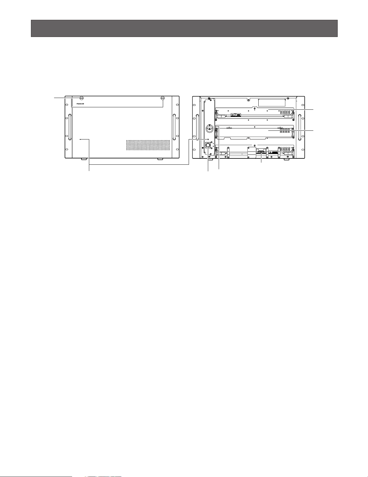
■ WJ-SX650 Matrix Switcher/WJ-SX650U Card Cage
● Front View
This is the illustration of WJ-SX650.
q Operation Indicator (OPERATE)
• This indicator is lighting while power is supplied to the
unit.
• This indicator blinks when the cooling fan has a trouble.
(Refer to p. 89.)
w Front Panel Fixing Screws
Before you press the power switch or install boards into
the expansion slot, these screw are removed to detach
the front panel
e Power Switch
r Expansion Slot
Optional video input or output main board is installed.
(Video Input Board WJ-PB65C32 or Video Output Board
WJ-PB65M16)
For WJ-SX650U, optional video input main board is
installed. (Video Input Board WJ-PB65C32)
t Video Input Board*
This is a video input main board. This board controls
cameras and alarm sensors (door switch, etc.).
Note: Refer to p. 11 WJ-PB65C32 Video Input Board for
details.
y Video Output Board*
This is a video output main board. This board controls
monitors and alarm output signals.
Note: Refer to p. 12 WJ-PB65M16 Video Output Board
for details.
* For WJ-SX650U, t and y are expansion slots.
9
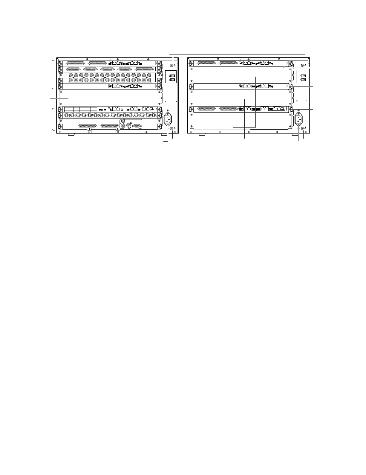
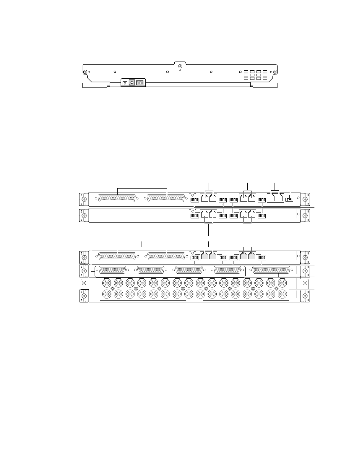
● Rear View
VIDEO OUT 3
VIDEO OUT 4
VIDEO OUT 2
MODEMODEMODEMODE
3
C
IN X-2
IN X-1
VIDEO OUT 1
ALARM IN
1
163215
31 30
14 13
29 28
12 11
27 26
10 9
25
CAMERA IN
24
87
23 22
65
21
2
B
1
2
3
20
43
19 18
21
17
DATA
DATA
EXTENSION 1
TERM.
OFF
ON
OUT
IN
OUT X-3
OUT X-2
OUT X-1
1234
AC IN
3
2
1
A
12345678
MONITOR OUT
910111213141516
ALARM OUT 2
ALARM OUT 1
SERIAL
VS OUT
VS IN
VS OUT
(THRU)
EXTENSION 3 IN
EXTENSION 2 IN
4
MODE
RS485 (CAMERA) RS485 (CAMERA)
3
MODE MODE MODE
2
1
IN C-3
4
MODE
RS485 (CAMERA) RS485 (CAMERA)
3
MODE MODE MODE
2
1
IN B-3
TERM.OFF
ON
MODE
TERM.ON
MODE
SIGNAL GND
DATA 4
HDR4/TMNL8
HDR2/TMNL4
DATA 3
HDR3/TMNL7
HDR1/TMNL3
DATA 2
TMNL6
TMNL2
DATA 1
TMNL5
TMNL1/PS DATA
Video Output Board 2
Video Output Board 1
SIGNAL GND
Video Output Board 1 Only
ON
4-Line
RS485(CAMERA) SET UP
MODE
ON
4-Line
MODE
3
C
1
2
B
1
2
3
AC IN
3
2
1
A
EXTENSION 3 IN
EXTENSION 2 IN
4
MODE
RS485 (CAMERA) RS485 (CAMERA)
3
MODE MODE MODE
2
1
IN C-3
SIGNAL GND
SIGNAL GND
ON
4-Line
RS485(CAMERA) SET UP
MODE
ON
4-Line
MODE
4
MODE
RS485 (CAMERA) RS485 (CAMERA)
3
MODE MODE MODE
2
1
IN B-3
EXTENSION 3 OUT EXTENSION 2 OUT
EXTENSION 1
TERM.
OFF
ON
OUT
IN
MODE
RS485 (CAMERA) RS485 (CAMERA)
MODE MODE MODE
IN A-3
!1
!1
!1
<WJ-SX650>
<WJ-SX650U>
u
!0 i!0
u
i
o
u Video Input Board Rear Panels*
These are video input rear boards.
Notes:
• Refer to p. 11 WJ-PB65C32 Video Input Board for
details.
• When installing a set of video output board into the
expansion slot of WJ-SX650, you will remove the IN
B-3 board, and install the OUT X-3 board.
i Expansion Slot
For WJ-SX650, optional video input or output rear
boards are installed. (Video Input Board WJ-PB65C32
or Video Output Board WJ-PB65M16)
For WJ-SX650U, optional video input rear boards are
installed. (Video Input Board WJ-PB65C32)
o Video Output Board Rear Panels
These are video output rear boards.
Note: Refer to p. 12 WJ-PB65M16 Video Output Board
for details.
!0 AC Inlet Socket (AC IN)
When using the unit, you will plug the power cord (supplied as a standard accessory) into this socket and
connect the cord to an AC outlet.
!1 Signal Ground Terminal (SIGNAL GND)
10
RESET
No.
MODE
qwe
VIDEO OUT 3
VIDEO OUT 4
VIDEO OUT 2
IN X-2
VIDEO OUT 1
ALARM IN
IN X-1
163215
31 30
14 13
29 28
12 11
27 26
10 9
25
CAMERA IN
24
87
23 22
65
21 20
43
19 18
21
17
EXTENSION 3 IN
EXTENSION 2 IN
4
MODE
RS485 (CAMERA) RS485 (CAMERA)
3
MODE MODE MODE
2
1
IN C-3
IN C-3 board
IN X-2 board
IN X-1 board
uu
i
!0
!1
4
3
MODE
RS485 (CAMERA) RS485 (CAMERA)
MODE MODE MODE
2
1
IN B-3
MODE
RS485 (CAMERA) RS485 (CAMERA)
MODE MODE MODE
4
3
2
1
EXTENSION 1
TERM.
OFF
ON
OUT
IN
IN A-3
EXTENSION 3 OUT
EXTENSION 2 OUT
IN A-3 board
IN B-3 board
tuur
i
y
oy
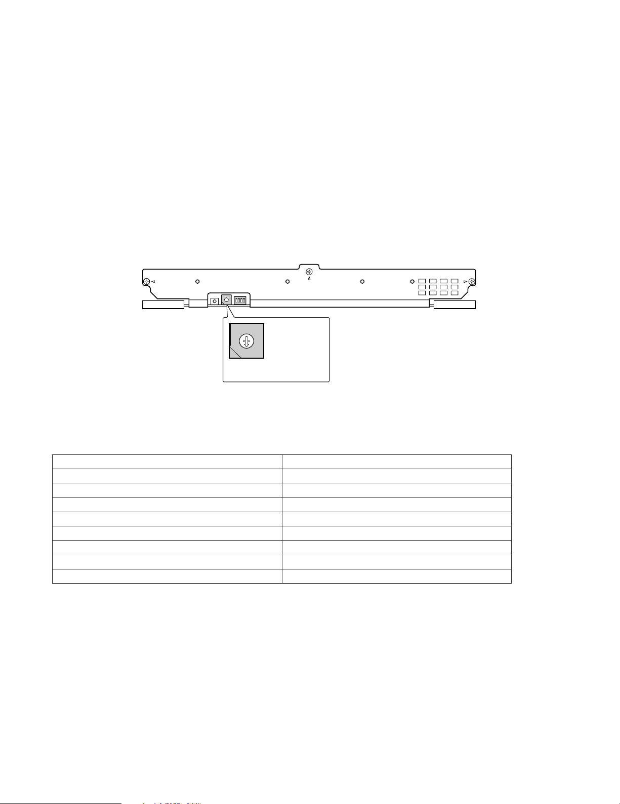
■ Video Input Board WJ-PB65C32
Video input board is composed of a main board (installed into the front side) and rear boards (x 3)(installed into the rear side).
● Front View
q Board Number Switch (No.)
Refer to p. 17 Switch Settings for Video Input Main
Board for details.
w Input Mode Selection Switches (MODE)
Set all switches to OFF.
● Rear View
e Reset Switch (RESET)
This button is pressed to reset this board.
Note: In normal operation, you need not press the but-
ton.
IN A-3/IN B-3/IN C-3 board
Note:
These boards are originally installed into WJ-SX650
and WJ-SX650U, and not supplied to optional video input
boards. (IN A-3 board is installed into WJ-SX650U only.)
r Extension Ports 1 (EXTENSION 1: IN, OUT)
These ports connect to an optional card cage.
t Termination Selector (TERM: ON, OFF)
Turns on or off the line termination of r.
y Extension Ports 2, 3 (EXTENSION 2, 3: IN, OUT)
Each port connects to an optional card cage.
u RS-485 Camera Ports 1 to 4 (RS485 (CAMERA) 1 to
4)
These ports connect to RS-485 cameras.
i RS-485 Camera Mode Switches 1 to 4 (MODE 1 to 4)
These switches are moved to change the communication modes of u.
IN X-2 board
o Video Output Ports 1 to 4 (VIDEO OUT 1 to 4)
These ports loop through video input signals supplied
to !1.
!0 Alarm Input Port (ALARM IN)
Connects to an alarm sensor (door switch, etc.).
IN X-1 board
!1 Camera Input Connectors 1 to 32 (CAMERA IN 1 to
32)
These connectors accept video input signals from cameras or recorders.
11
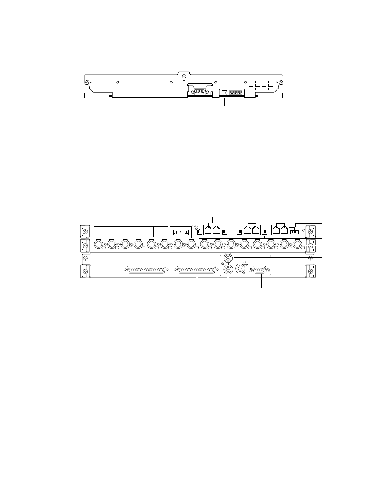
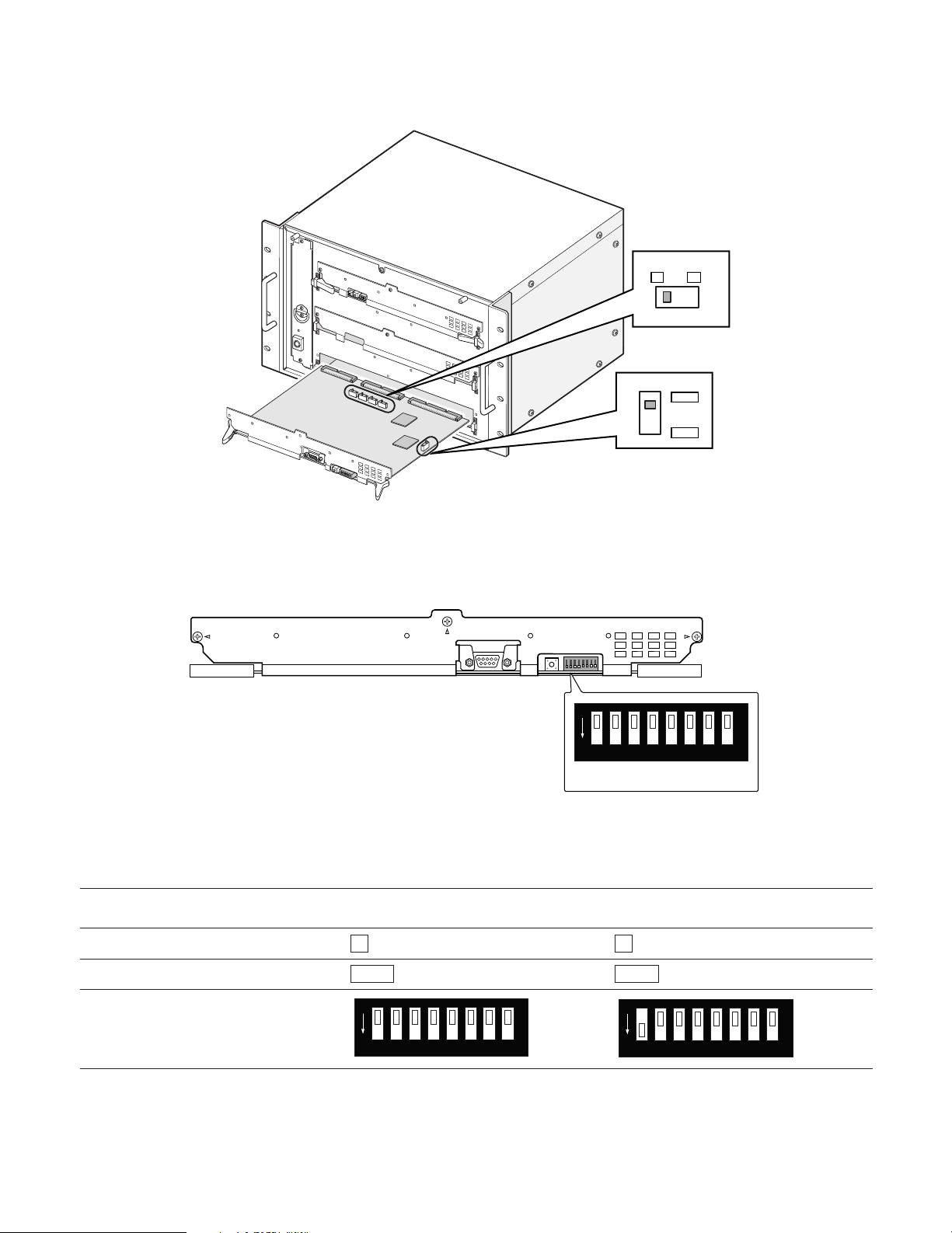
■ Video Output Board WJ-PB65M16
RESET
TEST
MODE
qwe
OUT X-2
12345678
MONITOR OUT
910111213141516
EXTENSION 1
TERM.
OFF
ON
OUT
IN
OUT X-3
MODEMODE
DATA
12
MODEMODE
DATA
34
TERM.OFF
ON
MODE
TERM.ON
MODE
DATA 4
HDR4/TMNL8
HDR2/TMNL4
DATA 3
HDR3/TMNL7
HDR1/TMNL3
DATA 2
TMNL6
TMNL2
DATA 1
TMNL5
TMNL1/PS DATA
Video Output Board 2
Video Output Board 1
OUT X-1
ALARM OUT 2
ALARM OUT 1
SERIAL
VS OUT
VS IN
VS OUT
(THRU)
Video Output Board 1 Only
ruy
t
i
o
!0
!1
!3
!4!2
OUT X-3 board
OUT X-2 board
OUT X-1 board
Video output board is composed of a main board (installed into the front side) and rear boards (x 3)(installed into the rear
side).
● Front View
q Output Mode Selection Switches (MODE)
Refer to p. 18 Switch Settings for Video Output Main
Board for details.
w Reset Switch (RESET)
This button is used only for factory tests. Do not press.
● Rear View
e Test port (TEST)
This port is used only for factory tests. Do not connect
anything.
OUT X-3 board
r Extension Ports 1 (EXTENSION 1: IN, OUT)
t Termination Selector (TERM: ON, OFF)
y Data ports 1, 2 (DATA 1, 2)
u Data ports 3, 4 (DATA 3, 4)
i Rear Termination MODE Switches 1 to 4 (MODE 1 to
12
These ports connect to an optional card cage.
Turns on or off the line termination of r.
Each port connects to system controllers.
Each port connects to system controllers or recorders.
4)
Turns on or off the line termination of y and u.
OUT X-2 board
o Monitor Output Connectors (MONITOR OUT 1 to 16)
These connectors connect to monitors.
OUT X-1 board
!0 Alarm Output Ports 1,2 (ALARM OUT 1, 2)
• Supplies alarm output signals.
• Accepts alarm recover input signals.
• Supplies and accepts the time adjust input and output
signals.
!1 VS Input Connector (VS IN)
Accepts a VS input signal from an external device.
!2 VS Output Loop-thru Connector (VS OUT (THRU))
Loops through VS input signals supplied to !1.
!3 VS Output Connector (VS OUT)
Supplies VS output signals to external devices. While !1
is accepting a VS input signal, !3 supplies an output
signal synchronizing the VS input signal. While !1 is not
accepting the VS input signal, !3 supplies an internal
synchronization output signal.
!4 Serial Port (SERIAL)
Connects to a PC.
Note: When q is set as Video Output Board 2, r, !1,
!2, !3, and !4 are not available.
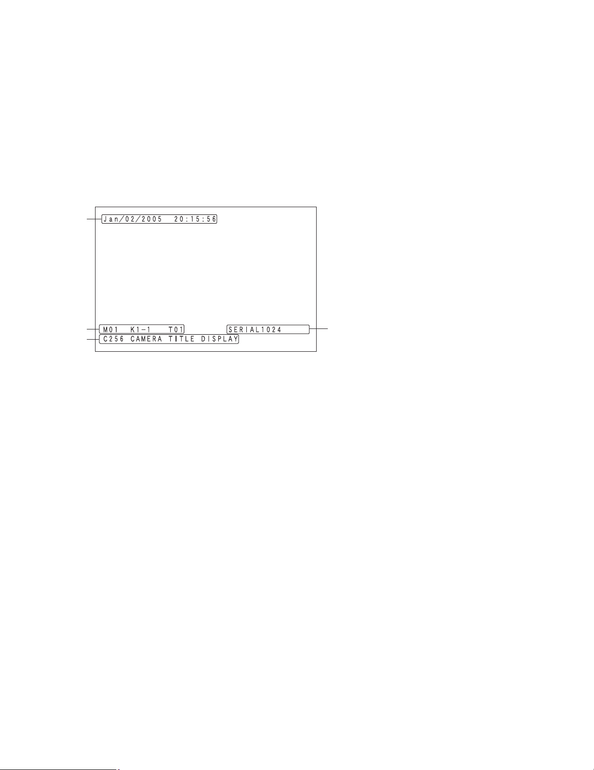
■ Monitor Display Information
The following are the details on terminal mode operations. For PS·Data operations, refer to p. 85 OPERATION (OTHER THAN
TERMINAL MODE) or the operating instructions of system controllers.
q
w
e
q Time and Date Information
Current time and date are displayed.
During daylight saving time (summer time), "∗" is displayed beside the time.
Example: Aug/02/2005 ∗20:15:56
Note: While a recorder is being selected, time and date
are not displayed.
w Monitor Status Information
Monitor number
M01 to 32: Monitor number
Note: During monitor lock, monitor number is highlight-
ed.
Controller information
Displays a device that selects and controls the monitor.
K1-1 to 8-4: Terminal mode system controller
(Example: For K8-4, "8" means the DATA port
(TMNL) number and "4" means the controller number of system controller.)
PSD: PS·Data mode system controller
PC: PC connected to the SERIAL port
/T001 to 128: Timer event
Sequence number
Displays the active sequence number.
T01 to 32: Tour sequence number
G01 to 32: Group sequence number
Note: During sequence pause, "P" is displayed beside
the sequence number.
r
e Camera Information
Camera number
C001 to 999: Camera number
R01 to 16: Recorder number
Camera title
Displays the registered camera title.
Camera title setting is performed in "Camera" – "Camera
Title" of WJ-SX650 Series Administrator Console.
r Event Information
TERMINAL001 to 256: Terminal alarm has occurred.
(Example: For TERMINAL001, "001" means the
number of alarm input signal accepted by the
ALARM IN port of video input board.)
CAMERA001 to 999: Camera alarm has occurred.
(Example: For CAMERA001, "001" means the number of camera supplying an alarm input signal to
the unit.)
RECORDER001 to 999: Recorder alarm has occurred.
(Example: For RECORDER001, "001" means the
number of camera associated with the recorder
supplying an alarm input signal to the unit.)
SERIAL0001 to 1024: Serial alarm has occurred.
(Example: For SERIAL0001, "0001" means the serial
command alarm input number.)
VIDEO LOSS001 to 999: Video loss has occurred.
(Example: For VIDEO LOSS001, "001" means the num-
ber of camera to which video loss has occurred)
SUSPEND: Alarm is suspended.
13
Notes:
• During the alarm acknowledgement (ACK) status (refer
to p. 68), event information is highlighted.
• When two or more alarm events have occurred, "∗" is
displayed beside the event information.
• When an alarm whose display mode setting is OFF
occurs, "#" is displayed beside the event information.
• When auto tracking is scheduled for a camera event, "#"
is displayed beside the camera number.
• q to r can be displayed or hidden either altogether or
separately. Refer to p. 73 Lists of Operations and
Functions for details.
■ System Controller Display Information
The following are the details on terminal mode operations.
For PS·Data operations, refer to p. 85 OPERATION (OTHER
THAN TERMINAL MODE) or the operating instructions of
system controllers.
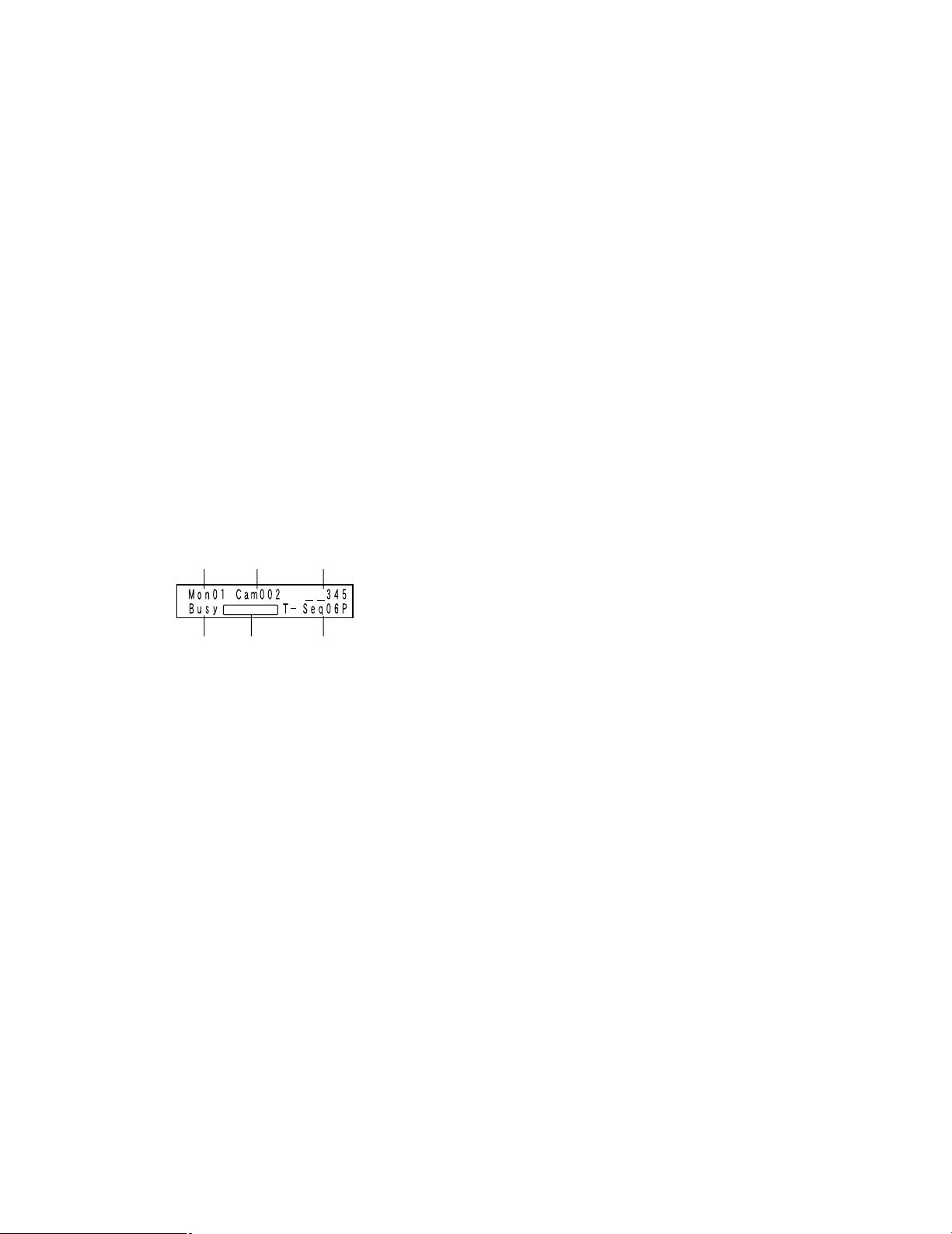
● WV-CU950/650
r Busy
Busy + monitor number (Blinking)
A selected monitor is controlled by a higher-priority
operator. (Monitor busy)
Note: You cannot control the selected monitor, camera,
and recorder.
Busy + camera/recorder number (Blinking)
A selected camera or recorder is controlled by a higher-priority user. (Camera/Recorder busy)
Note: You cannot control the selected camera or
recorder.
t Status
Alarm (Blinking): Alarm is occurring.
Alarm (Lighting): Alarm is acknowledged. (Refer to p.
68.)
Memory + preset position number (Blinking for 3.0 sec-
onds): Preset position is registered.
y Sequence Number
T-Seq01 to 32: Tour sequence number
G-Seq01 to 08: Group sequence number
Note: During sequence pause, "P" is displayed beside
the sequence number.
qw e
tyr
q Monitor Number
Mon01 to 32: Monitor number
w Camera Number
Cam001 to 999: Camera number
C-P0001 to 9999: Camera position number
e Event
HDR01 to 16: Recorder number
Pre000 to 256 (Lighting for 3.0 seconds): Preset position
Note: Pre000 is the home position.
T-A0001 to 0256: Terminal alarm
C-A0001 to 0999: Camera alarm
R-A0001 to 0999: Recorder alarm
S-A0001 to 1024: Serial alarm
V-A0001 to 0999: Video loss
G-Seq09 to 32: Group preset number
Note: This sign disappears when the camera is con-
trolled.
Invalid (Blinking for 3.0 seconds): You have entered a
wrong value.
Not Avail (Blinking for 3.0 seconds):
• You cannot select a monitor because of lower priority.
• You have tried to activate a group sequence or
group preset on a monitor not assigned.
Prohibited (Blinking for 3.0 seconds): You have tried an
operation restricted by the operator's setting.
Alarm Buzzer/Button Buzzer Setting
With the setting activated:
• Alarm buzzer can sound when alarms occur.
• Button buzzer can sound when a button is pressed or
an error message (Invalid, Prohibited, Level1 Fixed,
etc.) is displayed on the LCD.
Refer to the operating instructions of system controller
for settings.
14

● WV-CU360C/CJ
r
MONITOR CAMERA
qw
q Monitor number
01 to 32: Monitor number
w Camera/recorder/sequence number
001 to 999: Camera number
H01 to 16: Recorder number
t01 to 32: Tour sequence number
r01 to 08: Group sequence number
Note: During sequence pause, "P" is displayed instead
of "t" and "r".
BUSY PROHIBITED
When the PROHIBITED indicator is lighting:
• You have entered a wrong value.
• You have tried to activate a group sequence or
group preset on a monitor not assigned.
• You have tried an operation restricted by the operator's setting.
r09 to 32: Group preset number
Note: This sign disappears when the camera is con-
trolled.
e Event
The following signs appear to indicate events on the
LED display.
A0001 to 0256 (Blinking): Terminal alarm
A0001 to 0999 (Blinking): Camera alarm
A0001 to 0999 (Blinking): Recorder alarm
A0001 to 1024 (Blinking): Serial alarm
A0001 to 0999 (Blinking): Video loss
Note: During the alarm acknowledgement (ACK) status
(refer to p. 68), these signs change to steady light.
Pt000 to 256 (Lighting for 3.0 seconds): Preset position
Note: Pre000 is the home position.
Pr001 to 256 (Lighting for 3.0 seconds): Preset position
is registered.
r Indicators
When the MONITOR and BUSY indicators are light-
ing: A selected monitor is controlled by a higher-
priority user. (Monitor busy)
Note: You cannot control the selected monitor, camera,
and recorder.
When the CAMERA and BUSY indicators are light-
ing: A selected camera or recorder is controlled by
a higher-priority user. (Camera/Recorder busy)
Note: You cannot control the selected camera or
recorder.
15

Installations
CAUTION
These servicing instructions are for use by qualified service personnel only. To reduce the risk of electric shock do not
perform any servicing other than that contained in the operating instructions unless you are qualified to do so.
The following is the installation flow of this unit.
• Checking Board Composition
• Switch Settings for Video Input Main Board (Refer to p. 17.)
• Switch Settings for Video Output Main Board (Refer to p. 18.)
• Mounting Video Input and Output Boards (Refer to p. 19.)
• Board Mounting Procedure (Refer to p. 20.)
• Installing the Main Unit (Refer to p. 21.)
■ Checking Board Composition
By mounting additional video input and output boards, up to 256 cameras and 32 monitors can be connected to this unit. You
will choose one of the composition types described in the following diagram. Check how many video input boards, video output boars, and card cages are required, according to the number of cameras and monitors.
Note: Refer to p. 19 for the figures describing the composition types.
Total numbers of
cameras and
recorders
1 to 32
33 to 64 1 to 16 1 0 0 Type 3
65 to 96 1 to 16 2 0 1 Type 5
97 to 128 1 to 16 3 0 1 Type 7
129 to 160 1 to 16 4 0 1 Type 9
161 to 192 1 to 16 5 0 2 Type 11
193 to 224 1 to 16 6 0 2 Type 13
225 to 256 1 to 16 7 0 2 Type 15
Notes:
• When using 9 or more recorders, 2 sets of additional
video output board are required even if you use 16 or
less monitors.
• External monitors directly connected to recorders can
be excluded from the total number of monitor in the diagram.
• When connecting monitors directly to recorders, the
total numbers of these recorders can be excluded from
"Total number of cameras and recorders" in the diagram.
• Use the following models for system expansion.
Video input board: WJ-PB65C32
Total number of
monitors
1 to 16 0 0 0 Type 1
17 to 32 0 1 0 Type 2
17 to 32 1 1 1 Type 4
17 to 32 3 1 1 Type 6
17 to 32 3 1 1 Type 8
17 to 32 4 1 2 Type 10
17 to 32 6 1 2 Type 12
17 to 32 6 1 2 Type 14
17 to 32 7 1 3 Type 16
Additional sets of
video input board
Additional sets of
video output
board
Video output board: WJ-PB65M16
Card Cage: WJ-SX650U
• To connect Card Cage WJ-SX650U, Expansion Cable
Kit WJ-CA65L07K (Option) or WJ-CA65L20K (Option) is
required.
• To record camera images by using a recorder, Dsub/BNC Video Cable WJ-CA68 (Option) is required.
• The maximum set numbers of additional boards are as
follows.
Video input board: Max. 7 sets
Video output board: Max. 1 sets
Board sets exceeding these total numbers cannot be
mounted even some expansion slots are unused.
Additional card
cages
Composition type
(Refer to p. 19.)
16
Important:
• The software versions of Video Output Board 1 and 2
must be the same.
If the software version of each board is different,
upgrade the lower version to the higher one. (Refer to
p. 41 or p. 54 for how to check the software version.)
• Refer to the dealer for the version-up procedure. (Surely
follow the instructions and notes.)
■ Switch Settings for Video Input Main Board
With the switch settings of main boards, board numbers are given to all video input boards. To give the board number to each
board, rotate the Unit No. switch on the main board.
No.
RESET
MODE
9
A
8
B
7
C
6
5
D
4
E
3
F
2
0
1
Board number switch
Notes:
• The board number setting must be different from each other.
• "8", "9", and "A" to "F" are reserved settings. They cannot be set for board numbers.
Board number Switch setting
10
21
32
43
54
65
76
87
17
■ Switch Settings for Video Output Main Board
OFF
12345 6 7 8
OFF
12345 6 7 8
When mounting an additional video input board, up to 32 monitors can be connected to the unit.
SW1, SW2, SW3, SW4
1 2
SW4006
HOST
FUNC
Front view of video output main board
TEST
RESET
MODE
12345 6 7 8
OFF
MODE switches
To identify Video Output Board 1 from Video Output Board 2, set the MODE switches (SW4004) and sliding switches (SW1,
SW2, SW3, SW4, and SW4006) as follows.
SW1, SW2, SW3, SW4
SW4006
MODE switches (SW4004)
Video Output Board 1
(Monitor 1 to 16)
1
HOST
Video Output Board 2
(Monitor 17 to 32)
2
FUNC
Note: If the unit has only one Video Output Board, be sure to apply switch settings of Video Output Board 1. When the switch
settings are incorrect, the unit may not work properly.
18
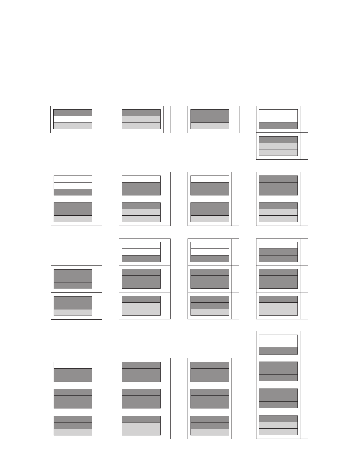
■ Mounting Video Input and Output Boards
Type 1
Not used
Video Input Board 1
Video Output Board 1
Type 2
Video Input Board 1
Video Output Board 2
Video Output Board 1
Type 3
Video Input Board 2
Video Input Board 1
Video Output Board 1
Type 4
Not used
Not used
Video Input Board 2
Video Input Board 1
Video Output Board 2
Video Output Board 1
Type 5 Type 6 Type 7 Type 8
Video Input Board 4
Video Input Board 3
Video Input Board 2
Video Input Board 1
Video Output Board 2
Video Output Board 1
Not used
Not used
Video Input Board 3
Video Input Board 2
Video Input Board 1
Video Output Board 1
Not used
Video Input Board 3
Video Input Board 2
Video Input Board 1
Video Output Board 2
Video Output Board 1
Not used
Video Input Board 4
Video Input Board 3
Video Input Board 2
Video Input Board 1
Video Output Board 1
Type 9 Type 10 Type 11 Type 12
Not used
Video Input Board 6
Video Input Board 5
Video Input Board 4
Video Input Board 3
Video Input Board 2
Video Input Board 5
Video Input Board 4
Video Input Board 3
Video Input Board 2
Video Input Board 1
Video Output Board 1
Not used
Not used
Video Input Board 5
Video Input Board 4
Video Input Board 3
Video Input Board 2
Video Input Board 5
Video Input Board 4
Video Input Board 3
Video Input Board 1
Video Output Board 2
Video Output Board 1
Video Input Board 1
Video Output Board 2
Video Output Board 1
Video Input Board 2
Video Input Board 1
Video Output Board 1
Not used
Not used
Video Input Board 6
Type 13 Type 14 Type 15 Type 16
Not used
Not used
Video Input Board 8
Video Input Board 7
Video Input Board 6
Video Input Board 5
Video Input Board 5
Video Input Board 6
Video Input Board 7
Video Input Board 4
Video Input Board 3
Video Input Board 2
Video Input Board 6
Video Input Board 7
Video Input Board 8
Video Input Board 5
Video Input Board 4
Video Input Board 3
Video Input Board 4
Video Input Board 3
Video Input Board 2
Video Input Board 1
Video Output Board 2
Video Output Board 1
Video Input Board 1
Video Output Board 2
Video Output Board 1
Not used
Video Input Board 7
Video Input Board 6
Video Input Board 5
Video Input Board 4
Video Input Board 3
Video Input Board 2
Video Input Board 1
Video Output Board 1
Video Input Board 2
Video Input Board 1
Video Output Board 1
To use additional video input or output boards, mount these boards into the expansion slots of the unit after checking the
board composition and performing switch settings (refer to pp. 16 to 18). The following is the figures describing recommended
board composition.
Notes:
• Refer to p. 20 for how to mount these boards.
• Video Output Board 1 and 2 must be mounted into the same unit.
• Refer to p. 26 for how to connect card cages.
19
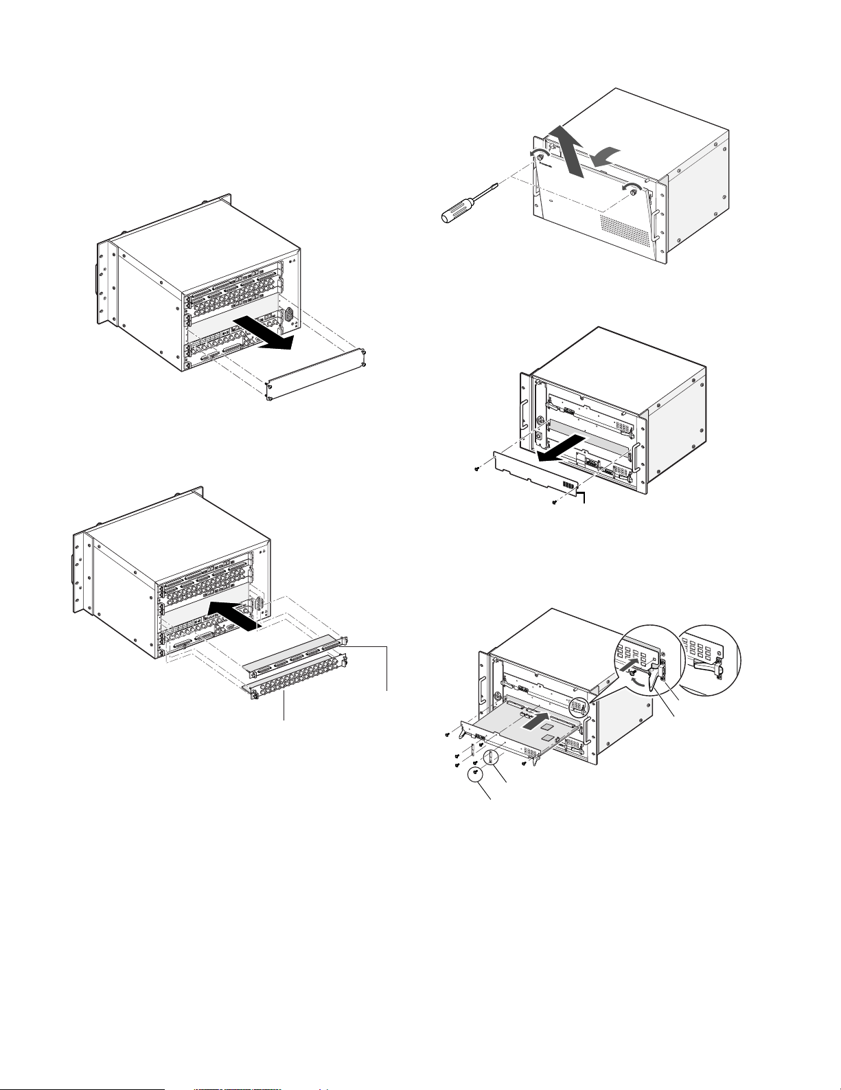
■ Board Mounting Procedure
The following example is the procedure to mount a network
board into the expansion slot of the unit.
Note: Before the procedure, power off the unit.
1. Remove the expansion slot panel from the rear side.
D
N
L G
A
N
IG
S
ND
N
O
.
M
R
E
T
F
F
N
O
O
.
M
R
E
T
E
D
1
O
M
A
T
DA
E
D
O
M
5
L
2
N
A
TM
AT
D
A
T
A
D
S
6
P
L
/
A 3
1
L
T
MN
N
A
T
M
D
T
L7
2
N
L
N
4
/TM
A
3
TM
T
R
DA
HD
L3
8
L
MN
/T
MN
/T
R1
4
D
R
H
HD
4
L
N
M
rd 2
/T
a
o
R2
t B
D
H
tpu
Ou
1
eo
rd
id
oa
V
t B
tpu
u
o O
e
id
V
2. Mount the rear boards into the expansion slot, and fix
these boards with screws supplied to the rear boards.
SIGNAL G
3. Remove the front panel by loosening the screws.
OPERATE
Matrix Switcher WJ-SX
650
4. Remove the blank panel from the front side.
ND
NAL G
SIG
D
N
G
L
A
N
IG
N
O
.
M
R
E
T
F
F
N
O
O
.
M
R
E
T
E
D
O
M
DATA 1
E
D
O
M
TMNL5
DATA 2
A
T
A
D
S
P
/
1
L
N
TMNL6
M
DATA 3
T
TMNL2
DATA 4
HDR3/TMNL7
HDR1/TMNL3
HDR4/TMNL8
HDR2/TMNL4
Video Output Board 2
Video Output Board 1
S
IN X-2 board
IN X-1 board
Notes:
• The board name (IN X-1, OUT X-1, etc.) is marked at
the lower right corner of each board mounting angle.
When mounting the rear boards, match the board
names with the markings at board mounting angles.
• To mount a set of video output board into the expansion
slot, dismount the IN B-3 board, and then mount the
OUT X-3.
Blank panel
5. Mount the main board by hooking the board stoppers
on the board stopper angles at the front side, by pushing down the board stoppers, and by fixing the screws.
Board stopper angle
Board stopper
Hook the board stoppers
on the board stopper angles, and
push down the board stoppers.
Fixing brackets* (x2)
Screws* (x4)
• Mount the main board into the slot.
• Fix the board with the screws (x3).
• Attach the fixing brackets (x2) with the screws (x4).*
* Required when mounting a video output board
(Not required when mounting a video input board)
20
Notes:
• Remove 3 screws surely at the arrow marking when dismounting.
• When mounting, match the main board surely with the
rear board.
• When mounting, insert the main board surely into slits.
• Do not hit the boards against the chassis of the unit.
■ Installing the Main Unit
Places to avoid
• Places exposed to direct sunlight or near a source of
heat such as a radiator
• Very dirty and dusty places
• Places subject to strong vibrations
• Near magnetic field sources such as a television or
speakers
• Near high-voltage cables such as a power cable
• Near noise sources such as fluorescent lamps
• Places where condensation forms easily
• Humid places
• Places where drastic temperature changes occur
• Places which are not level
• Steamy and oily places such as kitchens
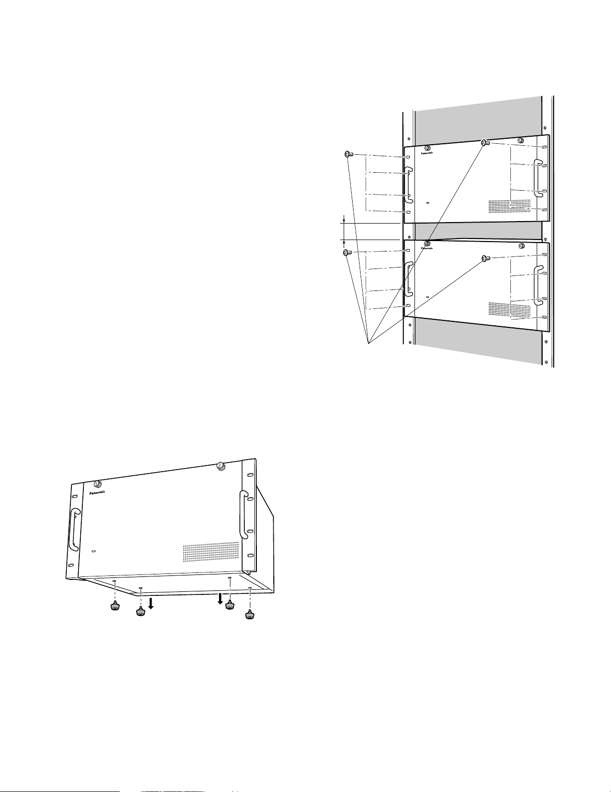
3. Mount the unit into the rack by fixing the rack mounting
screws (locally procured: 8 pcs). (Refer to the following
illustration.)
EIA 19 inch rack
650
Matrix Switcher WJ-SX
Rack Mounting
When mounting this unit, use the following racks.
Standard Rack: WU-RS71 (29 units can be mounted.)
Long Rack: WU-RL76 (41 units can be mounted.)
EIA equivalents (Products of other manufacturers): EIA
19 inch rack, 450 mm {17-7/10"} or more depth
Note: When mounting this unit into a rack of another manu-
facturer, Rack Mounting Screw (W2-MSS/5008) (Option)
or M5 x 12 screws (8 pcs.) are required.
1. Power off the unit.
2. Remove the rubber feet (4 psc.) on the bottom of the
unit by loosening the screws.
650
Matrix Switcher WJ-SX
Make a space equivalent to
approx. 1 unit (44 mm) or more
Matrix Switcher WJ-SX
650
Important:
• If the rack is subject to vibration, secure the rear of the
unit to the rack by using additional mounting brackets
(locally procured).
• To avoid loosening, secure the mounting screws surely.
• When operating the units, keep the temperature inside
the rack surely below 45 °C {113 °F}.
• Mount the unit into the rack with a space equivalent to
approx. 1 unit (44 mm) or more to separate from other
devices.
• Mounting ventilation fan(s) in the rack is recommended
especially when the rack is covered with front lids.
• To prevent the unit from overheating, do not block the
ventilation openings or slots in the cover
Remove the rubber feet.
21

Connections
Important:
Use only the recommended BNC connectors listed below.
RECOMMENDED
Tip dimensioins inside the BNC
fl 1.32 mm — fl 1.37 mm
Tip
(inside)
fl 0.13 mm — fl 0.69 mm
Standards
BNC
Video (coaxial) Cable
For U.S.A.
For Europe
For Japan
Suffixes attached to the standards may be updated.
Other BNC connectors may cause video signal interruption, and damage the BNC receptacles on the rear panel of the unit.
MIL-C39012C or MIL-C39012/16F
BS CECC 22120:1981
JIS C5412
22
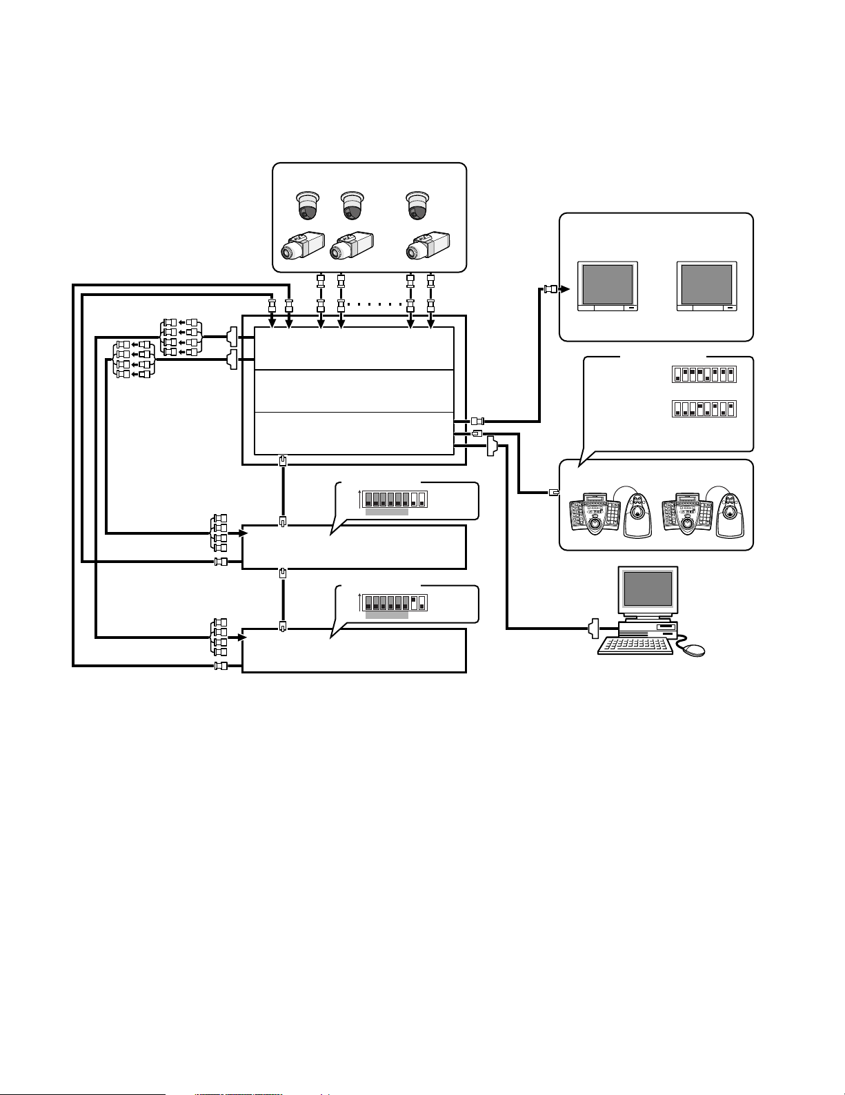
■ Basic System Connections
Video input board
Expansion slot
Video output board
A B
1
3
2
4
6
5
7
9
8
0
SYSTEM CONTROLLER
A B
1
3
2
4
6
5
7
9
8
0
SYSTEM CONTROLLER
System controller
SERIAL
DATA
DATA
CAMERA IN
CAMERA IN
CAMERA IN
MONITOR OUT
MONITOR OUT
MONITOR
OUT
Recorder
Recorder
~
~
~
PC (WJ-SX650 Series
Administrator Console)
78ON612345
78612345
78612345
78ON612345
Camera 1 to 30
Monitor 1 to 16
VIDEO OUT (Loop-thru output)
(#7: ON)
(#8: OFF)
(#7: OFF)
(#8: OFF)
MODE switches
MODE switches
MODE switches
WV-CU950/650
WV-CU360C/CJ
Terminal mode,
Line termination: ON
The following is a connection example to use one unit.
This unit x 1, camera x 30, monitor x 16, and recorder x 2
23
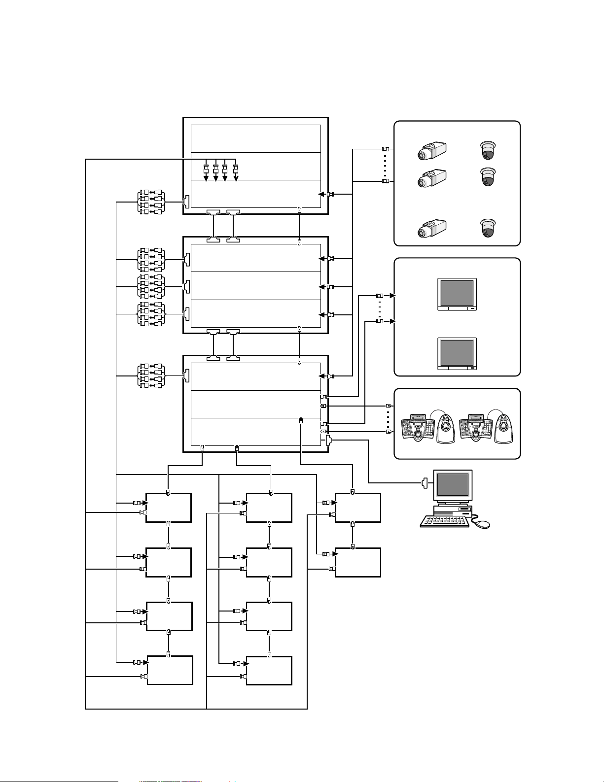
■ Expanded System Connections
~
~
~
A B
1
3
2
4
6
5
7
9
8
0
SYSTEM CONTROLLER
A B
1
3
2
4
6
5
7
9
8
0
SYSTEM CONTROLLER
Card cage connection
Card cage connection
CAMERA IN
CAMERA IN
CAMERA
IN
CAMERA
IN
VIDEO OUT
(Loop-thru output)
MONITOR OUT
MONITOR OUT
Recorder Recorder Recorder
Recorder Recorder
Recorder Recorder
Recorder Recorder
Recorder
Camera 1 to 150
Monitor 1 to 32
System controller
DATA
DATADATA
DATA
SERIAL
DATA
DATA
DATA
PC (WJ-SX650 Series
Administrator Console)
Video input board
Video input board
Video input board
Video input board
Video input board
Video output board
Video output board
The following is a connection example to use two or more units.
This unit x 3, camera x 150, monitor x 32, and recorder x 10
24
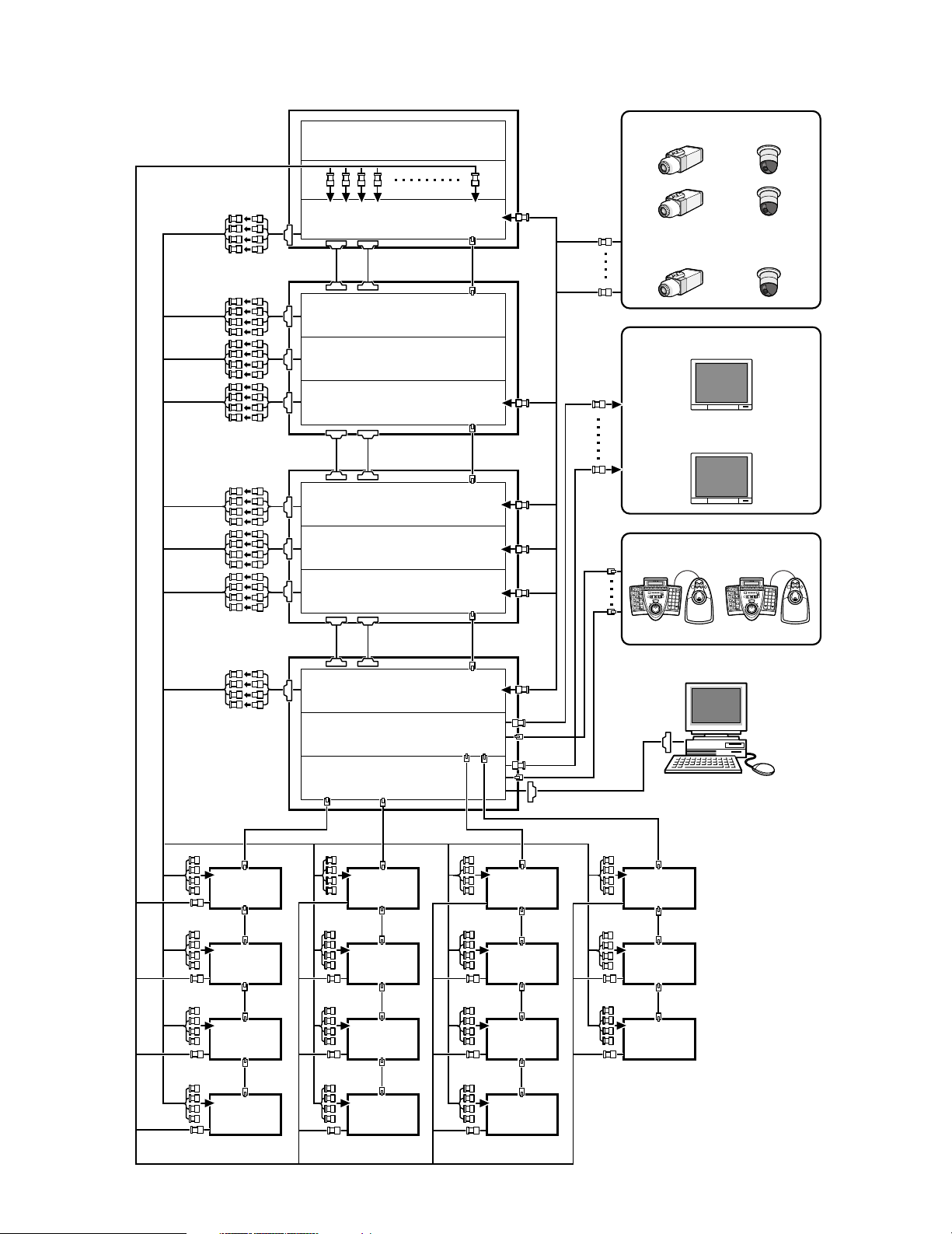
This unit x 4, camera x 240, monitor x 32, and recorder x 15
Recorder Recorder Recorder Recorder
Recorder Recorder Recorder Recorder
Recorder Recorder Recorder Recorder
Recorder Recorder Recorder
Card cage connection
Card cage connection
Card cage connection
Video input board
Video input board
Video input board
Video input board
Video input board
Video input board
Video input board
Video input board
Video output board
Video output board
A B
1
3
2
4
6
5
7
9
8
0
SYSTEM CONTROLLER
A B
1
3
2
4
6
5
7
9
8
0
SYSTEM CONTROLLER
~
~
~
DATA
DATA
DATADATA
DATA
SERIAL
DATA
DATADATA
DATA
DATA
DATA
DATA
DATA
Camera 1 to 240
Monitor 1 to 32
System controller
PC (WJ-SX650 Series
Administrator Console)
VIDEO OUT
(Loop-thru output)
CAMERA IN
CAMERA IN
CAMERA IN
MONITOR OUT
25

■ Card Cage Connections
3
C
1
2
B
1
2
3
AC IN
3
2
1
A
SIGNAL GND
SIGNAL GND
ON
4-Line
RS485(CAMERA) SET UP
MODE
ON
4-Line
MODE
EXTENSION 3 IN
EXTENSION 2 IN
4
MODE
RS485 (CAMERA) RS485 (CAMERA)
3
MODE MODE MODE
2
1
IN C-3
VIDEO OUT 3
VIDEO OUT 4
VIDEO OUT 2
IN X-2
VIDEO OUT 1
ALARM IN
4
MODE
RS485 (CAMERA) RS485 (CAMERA)
3
MODE MODE MODE
2
1
IN B-3
TERM.
OFF
ON
EXTENSION 1
OUT
IN
IN A-3
EXTENSION 3 OUT EXTENSION 2 OUT
IN X-1
163215
31 30
14 13
29 28
12 11
27 26
10 9
25
CAMERA IN
24
87
23 22
65
21 20
43
19 18
21
17
VIDEO OUT 3
VIDEO OUT 4
VIDEO OUT 2
IN X-2
VIDEO OUT 1
ALARM IN
IN X-1
163215
31 30
14 13
29 28
12 11
27 26
10 9
25
CAMERA IN
24
87
23 22
65
21 20
43
19 18
21
17
3
C
1
2
B
1
2
3
AC IN
3
2
1
A
SIGNAL GND
SIGNAL GND
ON
4-Line
RS485(CAMERA) SET UP
MODE
ON
4-Line
MODE
EXTENSION 3 IN
EXTENSION 2 IN
4
MODE
RS485 (CAMERA) RS485 (CAMERA)
3
MODE MODE MODE
2
1
IN C-3
VIDEO OUT 3
VIDEO OUT 4
VIDEO OUT 2
IN X-2
VIDEO OUT 1
ALARM IN
4
MODE
RS485 (CAMERA) RS485 (CAMERA)
3
MODE MODE MODE
2
1
IN B-3
EXTENSION 1
TERM.
OFF
ON
OUT
IN
IN A-3
EXTENSION 3 OUT EXTENSION 2 OUT
IN X-1
163215
31 30
14 13
29 28
12 11
27 26
10 9
25
CAMERA IN
24
87
23 22
65
21 20
43
19 18
21
17
VIDEO OUT 3
VIDEO OUT 4
VIDEO OUT 2
IN X-2
VIDEO OUT 1
ALARM IN
IN X-1
163215
31 30
14 13
29 28
12 11
27 26
10 9
25
CAMERA IN
24
87
23 22
65
21 20
43
19 18
21
17
3
C
1
2
B
1
2
3
AC IN
3
2
1
A
SIGNAL GND
SIGNAL GND
ON
4-Line
RS485(CAMERA) SET UP
MODE
ON
4-Line
MODE
VIDEO OUT 3
VIDEO OUT 4
VIDEO OUT 2
IN X-2
VIDEO OUT 1
ALARM IN
EXTENSION 3 IN
EXTENSION 2 IN
4
MODE
RS485 (CAMERA) RS485 (CAMERA)
3
MODE MODE MODE
21
IN C-3
MODEMODEMODEMODE
DATA
DATA
EXTENSION 1
TERM.
OFF
ON
OUT
IN
OUT X-3
1234
TERM.ON
ON
MODE
TERM.OFF
MODE
DATA 4
HDR4/TMNL8
HDR2/TMNL4
DATA 3
HDR3/TMNL7
HDR1/TMNL3
DATA 2
TMNL6
TMNL2
DATA 1
TMNL5
TMNL1/PS DATA
Video Output Board 2
Video Output Board 1
OUT X-2
12345678
MONITOR OUT
910111213141516
OUT X-1
ALARM OUT 2
ALARM OUT 1
SERIAL
VS OUT
VS IN
VS OUT
(THRU)
Video Output Board 1 Only
IN X-1
16 15 14 13 12 11 10 9
CAMERA IN
87654321
32 31 30 29 28 27 26 25 24 23 22 21 20 19 18 17
VIDEO OUT 3
VIDEO OUT 4
VIDEO OUT 2
IN X-2
VIDEO OUT 1
ALARM IN
IN X-1
163215
31 30
14 13
29 28
12 11
27 26
10 9
25
CAMERA IN
24
87
23 22
65
21 20
43
19 18
21
17
VIDEO OUT 3
VIDEO OUT 4
VIDEO OUT 2
IN X-2
VIDEO OUT 1
ALARM IN
IN X-1
163215
31 30
14 13
29 28
12 11
27 26
10 9
25
CAMERA IN
24
87
23 22
65
21 20
43
19 18
21
17
4
MODE
RS485 (CAMERA) RS485 (CAMERA)
3
MODE MODE MODE
2
1
Line termination: ON at the connection end
Line termination: ON at the connection end
Line termination: OFF
Expansion Cable Kit
WJ-CA65L20K or WJ-CA65L07K
4
MODE
RS485 (CAMERA) RS485 (CAMERA)
3
MODE MODE MODE
2
1
Card Cage WJ-SX650U is used for mounting additional Video Input Board WJ-PB65C32. Up to 3 video input boards can be
mounted into a card cage.
The following is a connection example to use additional card cages.
• Maximum unit connections: Matrix Switcher WJ-SX650 x 1, Card Cage WJ-SX650U x 3.
• Video Output Board 1 and 2 must be mounted into the same unit.
• Unit that has video output boards must be at the connection end.
• When connecting the EXTENSION 1 to 3 ports of each unit, use Expansion Cable Kit WJ-CA65L20K (Option) or WJ-
CA65L07K (Option).
• Connect nothing to the EXTENSION 1 port of the Video Output Board 2.
26
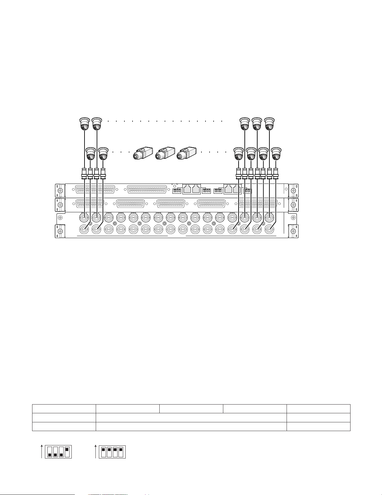
■ Camera Connections
The following is a connection example to use system cameras and combination cameras.
Notes:
• Make sure that the cable length is less than 900 m {3 000 ft} between the camera site and the unit when using RG-59/U,
BELDEN 9259 or equivalent cables.
• To display recorded images on monitors connected to this unit, connect the MONITOR OUT connectors of recorders to the
CAMERA IN connectors of the unit.
• When connecting cameras to the unit, reserve more unused connectors than the recorder total number. (Refer to p. 30
Recorder Connections for details.)
17
18193132
1516
1234
Combination
camera
System camera
1
21 20
43
ALARM IN
19 18
21
IN C-3
IN X-2
17
IN X-1
EXTENSION 3 IN
VIDEO OUT 4
163215
31 30
14 13
VIDEO OUT 3
29 28
12 11
EXTENSION 2 IN
27 26
VIDEO OUT 2
10 9
CAMERA IN
4
MODE
25
3
RS485 (CAMERA) RS485 (CAMERA)
MODE MODE MODE
24
87
VIDEO OUT 1
23 22
65
2
Video input rear board
■ RS-485 Camera Connections
There are two options to connect RS-485 cameras to this unit.
• 1:1 connection: One camera is connected to one RS-485 (CAMERA) port.
• Daisy chain connection: Up to 8 cameras can be connected to one RS-485 (CAMERA) port.
Notes:
• Set the line termination to ON for cameras at the connection ends. Line termination setting is performed with the MODE 1 to
4 switches (refer to p. 28) at video input rear boards.
• Perform the RS-485 camera setting in RS485 CAMERA of SETUP MENU (refer to p. 53) or "System" – "VD2/DATA/Cable
Comp." – "RS485 Camera" of WJ-SX650 Series Administrator Console.
• 1 200 m {3 937 ft} is the total length limit of RS-485 cables.
• Recommended for RS-485 communication is AWG#22 or thicker one. The cable should be shielded, two-wire, twisted pair,
and with low impedance.
• Conform the 2-wire or 4-wire communication setting of this unit to that of RS-485 cameras.
The following is the details on MODE 1 to 4 switch settings.
1234
ON
OFF
communication
ON
4-wire
1234
2-wire communication Line termination: ON
4-wire communication Line termination: OFF
2-wire
communication
ON
1234
27
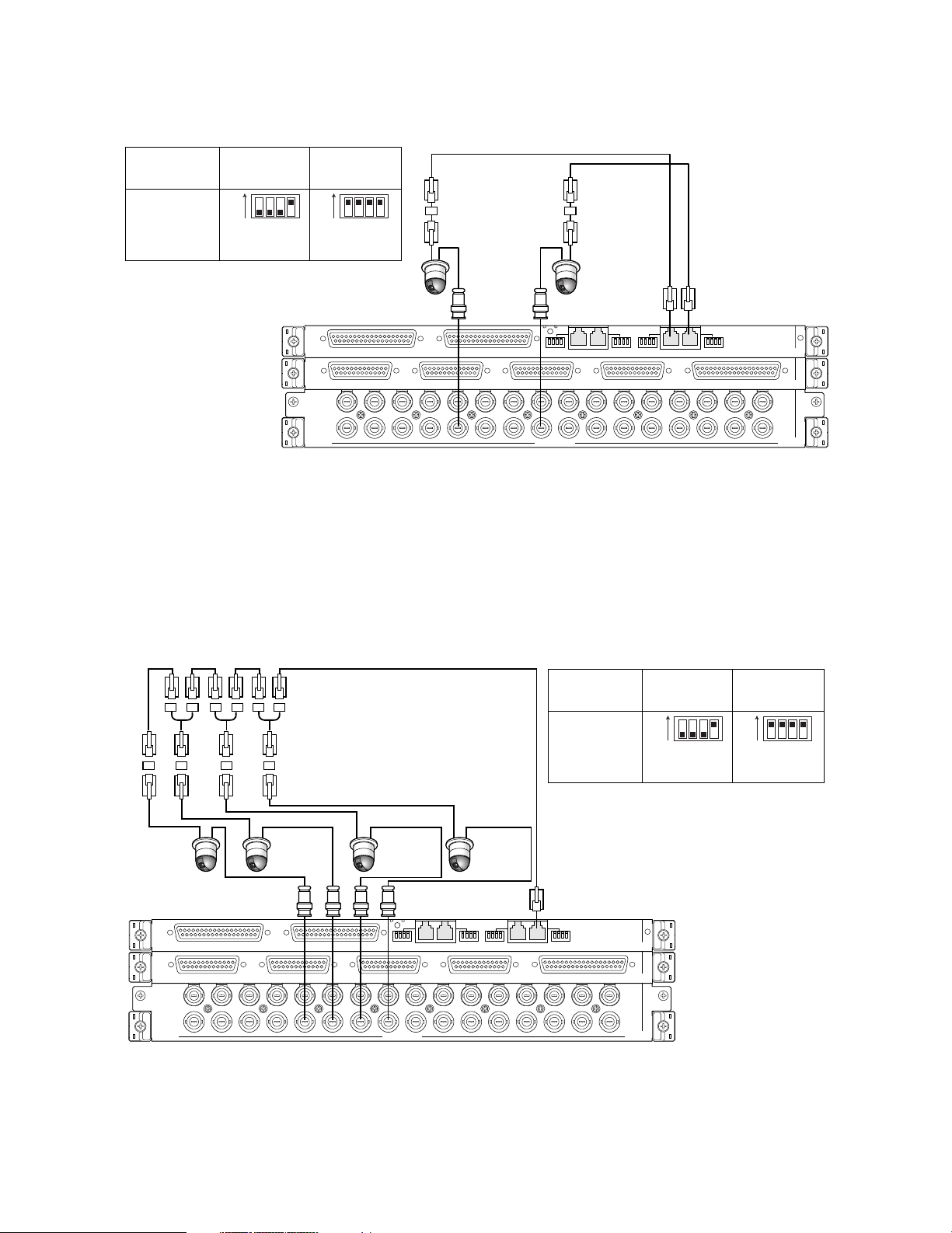
● 1:1 Connection
One camera is connected to one RS-485 (CAMERA) port.
Example: RS-485 cameras are connected to the CAMERA IN 9 and 12 connectors.
Connector
RS485
(CAMERA) 1
RS485
(CAMERA) 2
4-wire
communication
ON
1234
(SW#4: ON) (SW#1 to 4: ON)
MODE switch settings
2-wire
communication
ON
1234
Unit number: 1
Line termination: ON
EXTENSION 3 IN
VIDEO OUT 4
163215
31 30
14 13
VIDEO OUT 3
29 28
EXTENSION 2 IN
27 26
12 11
VIDEO OUT 2
10 9
CAMERA IN
Junction Unit
WV-CA48/JN
Unit number: 1
Line termination: ON
4
MODE
25
3
RS485 (CAMERA) RS485 (CAMERA)
MODE MODE MODE
VIDEO OUT 1
24
23 22
87
65
2
21 20
RS-485 cable
1
ALARM IN
19 18
43
21
IN C-3
IN X-2
17
IN X-1
Video input rear boards
Note: Do not use unit numbers other than 1 to 8 for individual cameras. (Refer to the operating instructions of camera for set-
ting.)
● Daisy Chain Connection
Two or more cameras can be connected to one RS-485 (CAMERA) port. Up to 8 cameras are available.
Example: RS-485 cameras are connected to the CAMERA IN 9 to 12 connectors
Connector
Unit number: 4
Line termination: ON
EXTENSION 3 IN
VIDEO OUT 4
163215
31 30
14 13
Daisy Chain Connection Kit
WV-CA48/10K
Junction Unit
WV-CA48/JN
Unit number: 3
Line termination: OFF
EXTENSION 2 IN
VIDEO OUT 3
29 28
12 11
27 26
10 9
Unit number: 2
Line termination: OFF
MODE
VIDEO OUT 2
CAMERA IN
Video input rear boards
RS-485 cable
Unit number: 1
Line termination: OFF
4
25
3
RS485 (CAMERA) RS485 (CAMERA)
MODE MODE MODE
VIDEO OUT 1
24
23 22
87
65
2
1
21 20
43
RS485
(CAMERA) 1
ALARM IN
19 18
21
4-wire
communication
ON
1234
(SW#4: ON) (SW#1 to 4: ON)
MODE switch settings
IN C-3
IN X-2
17
IN X-1
2-wire
communication
ON
1234
28
Notes:
• Among cameras connected to an RS485 (CAMERA) port in the daisy chain (4-wire communication), only one camera can
activate camera alarms.
• Do not use unit numbers other than 1 to 8 for individual cameras. (Refer to the operating instructions of camera for setting.)
• Do not set the same unit numbers for more than one camera in an RS-485 chain.

■ Monitor Connections
• The MONITOR OUT 1 to 16 connectors of Video Output Board 1 are assigned to Monitor 1 to 16.
• The MONITOR OUT 1 to 16 connectors of Video Output Board 2 are assigned to Monitor 17 to 32.
15
16
Video Output Board 2
Video Output Board 1
DATA 4
HDR4/TMNL8
HDR2/TMNL4
DATA 3
HDR3/TMNL7
HDR1/TMNL3
DATA 2
TMNL6
TMNL2
ALARM OUT 2
DATA 1
TMNL5
TMNL1/PS DATA
TERM.ON
MODE
ON
TERM.OFF
Video output rear boards
MODE
910111213141516
MONITOR OUT
ALARM OUT 1
DATA
3
4
VS OUT
DATA
SERIAL
12
MODEMODE
EXTENSION 1
OUT
Video Output Board 1 Only
34
MODEMODE
VS IN
VS OUT
(THRU)
1
2
OFF
ON
OUT X-3
IN
TERM.
12345678
OUT X-2
OUT X-1
■ PC Connection
Refer to Serial (RS-232C) Connector Command Reference (PDF file on the supplied CD-ROM) for details on the connection
and communication settings.
PC (WJ-SX650 Series
Administrator Console)
9-pin D-sub
(Female)
VS OUT
DATA
SERIAL
12
MODEMODE
EXTENSION 1
IN
OUT
Video Output Board 1 Only
OFF
TERM.
ON
OUT X-3
OUT X-2
OUT X-1
12345678
Video Output Board 2
Video Output Board 1
DATA 4
HDR4/TMNL8
HDR2/TMNL4
DATA 3
HDR3/TMNL7
HDR1/TMNL3
DATA 2
TMNL6
TMNL2
ALARM OUT 2
DATA 1
TERM.ON
TMNL5
TMNL1/PS DATA
ON
MODE
Video output rear boards
TERM.OFF
MODE
910111213141516
MONITOR OUT
ALARM OUT 1
DATA
34
MODEMODE
VS IN
VS OUT
(THRU)
29

■ Recorder Connection
The following is a connection example to use recorders.
Note: Use recorders with the following versions.
• WJ-HD300 Series: Ver. 1.61 or later
• WJ-HD300A Series: Ver. 3.10 or later
● Connection to Video Output Connectors of Recorders
To display recorder images on monitors connected to this unit
When the video output connectors of recorders are connected to CAMERA IN connectors of this unit, recorder images can be
displayed on Monitor 1 to 32.
The following is the connection procedure.
1. Assign Unit Address (System) to the recorders. (Refer to p. 34 q.)
Available unit addresses are 1 to 16. The unit address setting must be different from each other.
2. Decide the video input board to supply video input signals from recorder.
Choose a video input board that has more unused connectors (CAMERA IN 17 to 32) than the recorder total number.
Note: Only one video input board can be connected to the video output connector of recorders.
3. Connect the video output connectors (the monitor output 2 connector) of recorders and the CAMERA IN 17 to 32 connectors of the unit.
Recorder number
(Unit Address (System))
1
2
3
4
5
6
7
8 251617
Note: To supply video input signals from recorders to video input boards, perform the settings surely in RECORDER of SETUP
MENU (refer to p. 50) or "System" – "Recorder" of WJ-SX650 Series Administrator Console.
CAMERA IN connector of
video input board
32 9 24
31 10 23
30 11 22
29 12 21
28 13 20
27 14 19
26 15 18
Recorder number
(Unit Address (System))
CAMERA IN connector of
video input board
30
 Loading...