

Panasonic WJ-SX350 User Manual
ENGLISHDEUTSCHFRANÇAISESPAÑOL
Matrix Switcher
WJ-SX350
Before attempting to connect or operate this product, please read these instructions completely
The serial number of this product may be found on the
left of the unit.
You should note the serial number of this unit in the
space provided and retain this book as a permanent
record of your purchase to aid identification in the event
of theft.
Model No.
Serial No.
The lightning flash with arrowhead symbol, within an equilateral triangle, is
interned to alert the user to the presence
of uninsulated "dangerous voltage" within
the product's enclosure that may be of
sufficient magnitude to constitute a risk of
electric shock to persons.
The exclamation point within an equilateral triangle is intended to alert the user
to the presence of important operating
and maintenance (servicing) instructions
in the literature accompanying the appliance.
WARNING:
TO PREVENT FIRE OR ELECTRIC SHOCK HAZARD, DO NOT EXPOSE THIS APPLIANCE TO RAIN OR MOIS
TURE.
CAUTION:
TO REDUCE THE RISK OF ELECTRIC SHOCK,
DO NOT REMOVE COVER (OR BACK), NO USER
SERVICEABLE PARTS INSIDE.
REFER SERVICING TO QUALIFIED SERVICE
PERSONNEL.
CAUTION
RISK OF ELECTRIC SHOCK
DO NOT OPEN
ENGLISH VERSION
FOR YOUR SAFETY PLEASE READ THE FOLLOWING TEXT
CAREFULLY.
WARNING
THIS APPARATUS MUST BE EARTHED
IMPORTANT
The wires in this mains lead are coloured in accordance with the following code.
Green-and-yellow: Earth
Blue: Neutral
Brown: Live
As the colours of the wire in the mains lead of this appliance may
not correspond with the coloured markings identifying the terminals in
your plug, proceed as follows.
The wire which is coloured green-and-yellow must be connected
to the terminal in the plug which is marked with the letter E or by the
earth symbol
I or coloured green or green-and-yellow.
The wire which is coloured blue must be connected to the terminal
in the plug which is marked with the letter N or coloured black.
The wire which is coloured brown must be connected to the terminal in the plug which is marked with the letter L or coloured red.
Wij verklaren als enige aansprakelijke, dat het product waarop deze
verklaring betrekking heeft, voldoet aan de volgende normen of
andere normatiefve dokumenten, overeenkomstig de bepalingen
van Richtlijnen 73/23/EEC en 89/336/EEC.
Vi erklærer os eneansvarlige for, at dette produkt, som denne
deklaration omhandler, er i overensstemmelse med den følgende
standarder eller andre normative dokumenter i følge bestem-
melserne i direktivene 73/23/EEC og 89/336/EEC.
Vi deklarerar härmed värt fulla ansvar för att den produkt till vilken
denna deklaration hänvisar är i överensstämmelse med standard-
dokument, eller andra normativa dokument som framstölls i Direktiv
73/23/EEC och 89/336/EEC.
Ilmoitamme yksinomaisella vastuullamme, että tuote, jota tämä
ilmoitus koskee, noudattaa seuraavia standardeja tai muita ohjeel-
lisia asiakirjoja, jotka noudattavat direktiivien 73/23/EEC ia
89/336/EEC. säädöksiä.
Vi erklærer oss alene ansvarlige for at produktet som denne
erklæringen gjelder for, er i overensstemmelse med følgende
normer eller andre normgivende dokumenter som fælger bestem-
melsene i direktiven 73/23/EEC og 89/336/EEC.
We declare under our sole responsibility that the product to which
this declaration relates is in conformity with the standards or other
normative documents following the provisions of Directives
EEC/73/23 and EEC/89/336.
Noi dichiariamo sotto nostra esclusiva responsabilità che il prodotto
a cui si riferisce la presente dichiarazione risulta conforme ai
seguenti standard o altri documenti normativi conformi alle disposizioni delle direttive CEE/73/23 e CEE/89/336.

-1-
CONTENTS
PREFACE ................................................................................................................................................................................ 2
FEATURES .............................................................................................................................................................................. 2
PRECAUTIONS ....................................................................................................................................................................... 3
HOW TO USE THIS MANUAL ................................................................................................................................................. 4
FEATURES OF THE MATRIX SWITCHER ................................................................................................................................. 5
FEATURES OF THE MATRIX SWITCHER ............................................................................................................................. 6
DETAILED PRODUCT DESCRIPTION .................................................................................................................................... 15
MAJOR OPERATING CONNECTIONS ................................................................................................................................ 16
INSTALLATIONS AND SYSTEM CONNECTIONS .................................................................................................................. 21
INSTALLATIONS .................................................................................................................................................................. 22
SYSTEM CONNECTIONS .................................................................................................................................................... 24
SOFTWARE SETUP ................................................................................................................................................................ 27
SETUP MENU ...................................................................................................................................................................... 29
PROGRAM MENU ............................................................................................................................................................... 30
OPERATOR .......................................................................................................................................................................... 38
SYSTEM ............................................................................................................................................................................... 40
DATA LOAD ......................................................................................................................................................................... 44
CAMERA TITLE..................................................................................................................................................................... 46
CAM-POSI SET (Camera Position Set) ................................................................................................................................ 47
FUNCTION KEY MODE ........................................................................................................................................................ 48
OPERATING PROCEDURES .................................................................................................................................................. 49
Log-in.................................................................................................................................................................................... 50
Monitor Selection .................................................................................................................................................................50
Camera Selection ................................................................................................................................................................ 51
Lens Control ......................................................................................................................................................................... 51
Pan/Tilt Control .....................................................................................................................................................................52
Camera Housing Control .....................................................................................................................................................53
Running Sequence ..............................................................................................................................................................54
On Screen Display ............................................................................................................................................................... 55
Camera Function Control ......................................................................................................................................................56
Camera Set Up ....................................................................................................................................................................58
Auxiliary Control ................................................................................................................................................................... 59
Control History Mode ........................................................................................................................................................... 59
Alarm Control ....................................................................................................................................................................... 59
Alarm Recall .........................................................................................................................................................................60
Camera Site Status Display ..................................................................................................................................................61
System Status Display ..........................................................................................................................................................61
Priority Lock ..........................................................................................................................................................................62
Log-out .................................................................................................................................................................................62
SPECIFICATIONS ....................................................................................................................................................................63
SPECIFICATIONS .................................................................................................................................................................64
STANDARD ACCESSORIES .................................................................................................................................................65
ENGLISH

-2-
The WJ-SX350 Matrix Switcher allows for flexible control
of thirty two (32) cameras and eight (8) monitors.
Tour and Group sequences for customized security
requirements can be easily established through the
user-friendly, on-screen menu setups.
PREF ACE
FEATURES
The WJ-SX350 Matrix Switcher enables control of the
following functions:
• Routing of up to thirty-two (32) cameras to any one
of eight (8) monitors.
• Remote control of up to thirty-two (32) cameras and
auxiliary equipment, by using optional Receivers
and accessories, including:
1. Remote control of Pan-Tilt Head and Camera
Housing.
2. Remote control of Motorized Zoom Lenses:
Focus, Zoom and Iris.
3. Remote control of camera setting, including
Electronic Sensitivity Up, Electronic Shutter and
more.
Additional features of the WJ-SX350 includes:
Versatile Camera Switching Modes
• Thirty-two (32) tours including Dwell Time, Camera
Preset Position and AUX Controls for any monitor
• Four (4) group synchronized sequences including
Dwell Time, Camera Preset Positions and AUX
Controls
• Any Tour or Group synchronized sequence can be
selected by operators manually. If Alarm and Time
Event schedules are set up, the sequence activates automatically.
Flexible Alarm Activation
• Alarm Mode 1: Any alarm is displayed on one designated monitor, and one associated Time Lapse
VTR is switched to real time mode.
• Alarm Mode 2: Any alarms are displayed on four
designated monitors, and four associated Time
Lapse VTRs are switched to real time mode.
• Alarm Mode 3: Any alarms are displayed on any
monitors, together with sequence routines and presets.
Alternatively, any Tour or Group sequence can be
assigned to any monitor or group of monitors.
Programmable System Partitioning and Priority
• Operator Registration: Three (3) operator access
levels to system for setup and operation.
Password protection to limit operators access to
system.
Operator priority to lock out access by lower priority operators.

-3-
• Refer all work related to the installation of this
product to qualified service personnel or system
installers.
• Do not block the ventilation opening or slots on
the cover.
To prevent the appliance from overheating, place
the appliance at least 5 cm (2 inches) away from
the wall.
• Do not drop metallic parts through slots.
This could permanently damage the appliance.
Turn the power off immediately and contact qualified service personnel for service.
• Do not attempt to disassemble the appliance.
To prevent electric shock, do not remove screws or
covers.
There are no user-serviceable parts inside. Contact
qualified service personnel for maintenance.
• Handle the appliance with care.
Do not strike or shake, as this may damage the
appliance.
• Do not expose the appliance to water or
moisture, nor try to operate it in wet areas.
Do take immediate action if the appliance becomes
wet. Turn the power off and refer servicing to qualified service personnel. Moisture may damage the
appliance and also cause electric shock.
• Do not use strong or abrasive detergents when
cleaning the appliance body.
Use a dry cloth to clean the appliance when it is
dirty.
When the dirt is hard to remove, use a mild detergent and wipe gently.
• Do not operate the appliance beyond its
specified temperature, humidity or power source
ratings.
Do not use the appliance in an extreme environment where high temperature or high humidity
exists.
Use the appliance at temperatures within –10°C +50°C (14°F - 122°F) and a humidity below 90%.
The input power source for this appliance is 220 240 V AC 50 Hz.
PRECAUTIONS

-4-
HOW TO USE THIS MANUAL
The purpose of this manual is to provide step-by-step instructions for setting up and operating a Matrix Switcher System. If
a Matrix Switcher is new to you, it is highly recommended that you read through this manual. If you are already familiar with
the Matrix Switcher, you may skip Sections 1 and 2 and start from Section 3, Installations and System Connections. The
contents of each section of this manual are summarized below.
Section 1 Features of the Matrix Switcher
Describes the main features of the System. Numerous illustrations provide easy-to-understand explanations.
Section 2 Detailed Product Description
Operating controls and their functions are explained in this section.
Section 3 Installations and System Connections
Information about cable connections between the Matrix Switcher and System Controllers, cameras, monitors and peripheral devices is provided here.
Section 4 Software Setup
Step-by-step procedures for successful initial programming of the system are explained in this section.
Graphical representations of the various setup tables are also provided. This section is very important as
proper programming of the system is vital for customizing the system to the end user’s requirements.
Section 5 Operating Procedures
After system programming, normal operation of the system on a daily basis is done by following the steps
outlined in this section.
Section 6 Specifications

-5-
SECTION 1
FEATURES
OF THE
MATRIX
SWITCHER
-6-
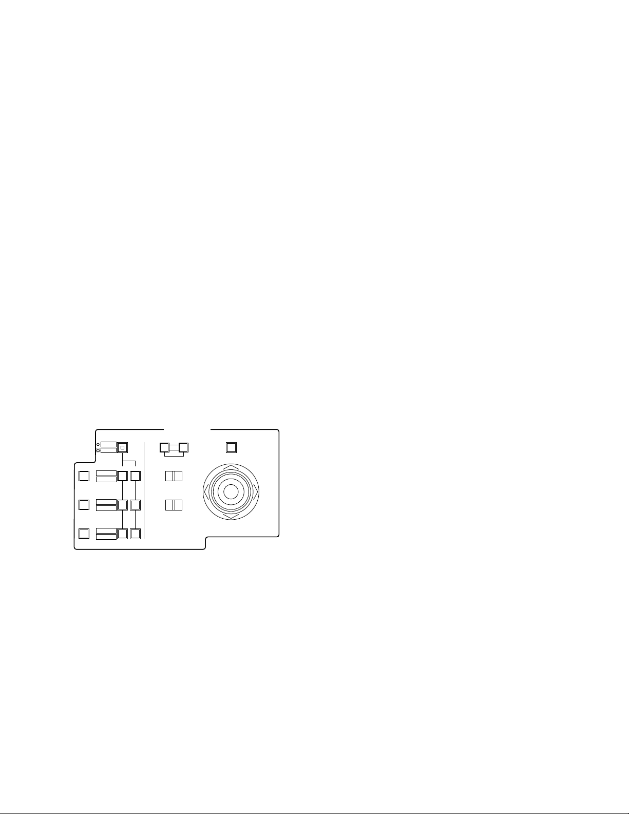
FEATURES OF THE MATRIX SWITCHER
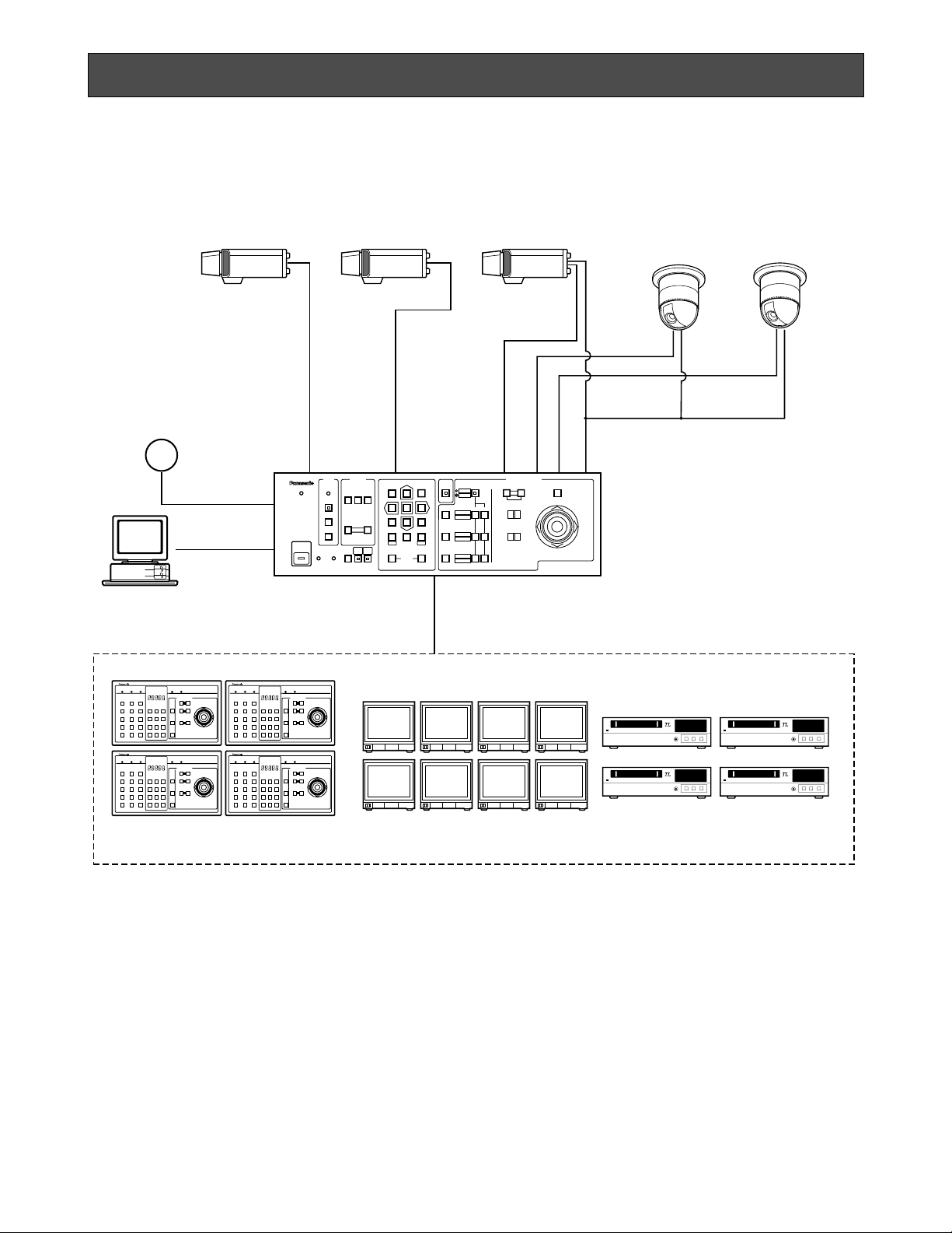
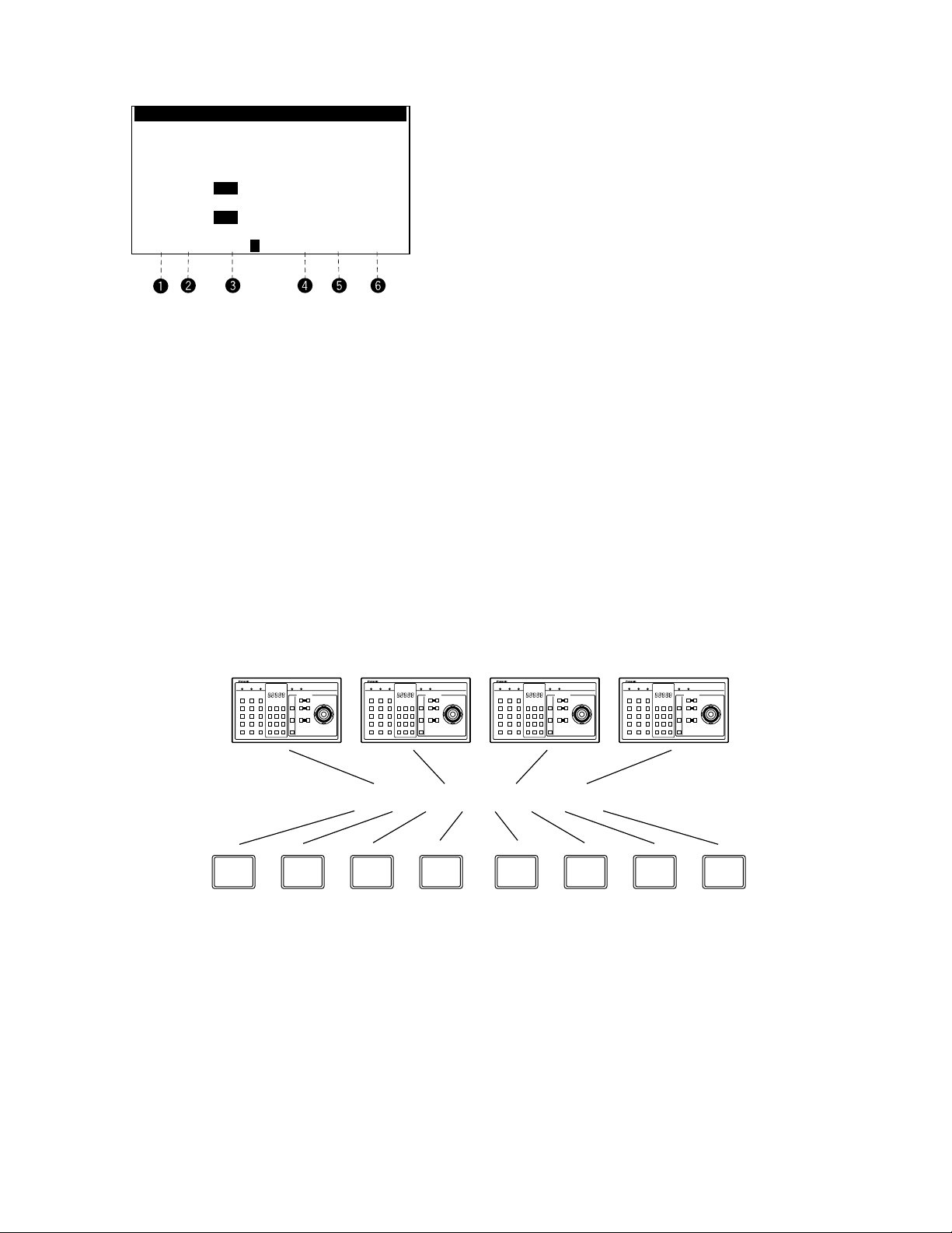
Shown below is an example of a basic system of the WJ-SX350 Matrix Switcher.
LOGIN
BUSY
PROHIBITED STATUS
ALARM
ALARM
SEQUENCE
ACK/RESET
OPERATE
ALL RESET
RECALL
CAM
MENU
SET UP
PAUSE
BACK
SEQ
FWD
SEQ
−1 CAM
DEC
DEC
+1 CAM
INC
321
654
987
FWD
ALT SHIFT
AUTO FOCUS
FUNCTION
ON OFF
PRESET
POSI
CAM
POSI
BACK
CAM
0
MON
SETESC
HISTORY
AUTO PAN
RANDM PAN
AUX 1
WIPER
AUX 2
DEF
IRIS
CLOSE
NEAR FAR
OPEN
IRIS RESET
FOCUS
TELE WIDE
LEFT
UP
DOWN
ZOOM
MATRIX SWITCHER WJ-SX350
CAMERA SITE CONTROL
Video
Data RS-485
Up to 32 Cameras
32-Alarm Input
System Controller
(Max.4 Units)
Video Monitor(Max.8 Outputs)
Time Lapse VTR
(Max.8 Control Outputs)
Matrix Switcher
WJ-SX350
L
CLOSE
OPEN
IRIS
R
UP
DOWN
NEAR
FAR
FOCUS
BUSY
TELE
WIDE
ZOOM
0
987
654
321
ALARM MONITOR CAMERALOCKPOWER PROHIBITED
CAMERA SITE CONTROL
L
CLOSE
OPEN
IRIS
R
UP
DOWN
NEAR
FAR
FOCUS
BUSY
TELE
WIDE
ZOOM
0
987
654
321
ALARM MONITOR CAMERALOCKPOWER PROHIBITED
CAMERA SITE CONTROL
L
CLOSE
OPEN
IRIS
R
UP
DOWN
NEAR
FAR
FOCUS
BUSY
TELE
WIDE
ZOOM
0
987
654
321
ALARM MONITOR CAMERALOCKPOWER PROHIBITED
CAMERA SITE CONTROL
L
CLOSE
OPEN
IRIS
R
UP
DOWN
NEAR
FAR
FOCUS
BUSY
TELE
WIDE
ZOOM
0
987
654
321
ALARM MONITOR CAMERALOCKPOWER PROHIBITED
CAMERA SITE CONTROL
Camera Input: Up to thirty-two (32) cameras can be
connected. The pan/tilt head, zoom /focus/iris of the
lens and auxiliary switching can be controlled. Also
preset control of the lens and pan/tilt head position
is possible by using the WV-CSR600 series
Combination Camera System.
Monitor Output: Up to eight (8) monitors can be con-
nected. The camera title, camera and monitor number and alarm condition can be displayed on the
monitor screen.
System Controller: Up to four (4) controllers may be
connected. A variety of controls are accessible
through the monitor display. The system Controller
also provides access to the Setup Menu and Tables
for programming.
VTR: Up to eight (8) VTRs can be connected. The video
signal controlled by the WJ-SX350 Matrix Switcher
is supplied to the VTRs.
Also, the Matrix Switcher can supply the VTRs with
an alarm output signal to switch time lapse recording mode.
Alarm Input: Up to thirty-two (32) alarm signals can be
supplied. An Alarm Sensor with a Normally Open
circuit should be used.
RS-232C Port: The Matrix Switcher can be substituted
by connecting a Personal Computer to control the
system.
Note: For using a Personal Computer, you will need
special software offered separately.
-7-
1. Log-in
To operate the Matrix Switcher System, a registered
operator must first supply his/her Operator Number and
Password to the system.
The operator number and password are established by
using the REGISTRATION table, See page 39 for more
details on operator number registration.
If an attempt is made to enter an operator number and
password that do not match with the registered operator
numbers and passwords, entry into this system is
denied.
As shown in the examples below, there are two (2) additional attributes associated with an operator: operator
level and priority. These items are described in more
detail on page 11.
Note:
Initially,
Operator Number: 1
Password: 12345
are registered at the factory to allow access for first
time system programming.
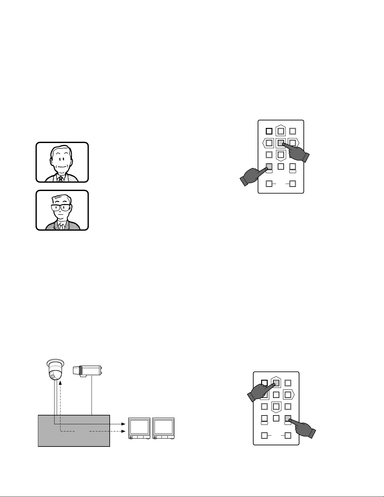
2. Camera and Monitor Selection
After logged in, the desired camera and monitor combination can be selected.
Basically, any combination of camera and monitor,
which are connected to the Switcher, can be selected
as shown below.
Operator Name: Mike
Operator Number: 1
Operator level: 1
Password: 07171
Priority: 1
Operator Name: Robert
Operator Number: 15
Operator level: 3
Password: 11524
Priority: 8
General Procedures
1. Select the desired monitor. (Monitor and Switcher
are linked.)
2. Select the desired camera (Camera and Switcher
are linked.)
3. The picture of the selected camera view is displayed on the selected monitor.
2-1. Monitor Selection
Press the Numeric button (1-8), then press the MON
(ESC) button to select the desired monitor.
For example:
When selecting Monitor Number 5:
Press 5, then press the MON (ESC) button.
Note: The desired monitor selection may not be avail-
able due to one of the following reasons:
1. The system controller used for selecting a particular
monitor is not allowed access to that monitor
because of controller partitioning.
See page 13 for more details.
2. The desired monitor is currently selected by another
operator who has a higher operator priority, and
therefore, control over that monitor.
In this case, the BUSY Indicator blinks.
2-2. Camera Selection
The video signal from the desired camera can be supplied to the selected monitor. Press the Numeric buttons
(1-32), then press the CAM (SET) button to select the
desired camera.
321
654
987
FWDBACK
CAM
0
MON
SETESC
HISTORY
For example:
When selecting Camera Number 2:
Press 2, then press the CAM (SET) button.
321
654
987
CAM
0
MON
HISTORY
SETESC
FWDBACK
3
12
Matrix Switcher
WJ-SX350
Monitor 1 Monitor 2
-8-
Note: The desired camera selection may not be avail-
able due to one of the following reasons:
1. The operator is not allowed access to the desired
camera because the Operator Registration has limited the operator's access to certain cameras.
At this time PROHIBITED Indicator light up. See
page 11 for more details.
2. The desired camera is currently selected by another operator who has a higher operator priority, and
therefore, control over that camera.
In this case, the BUSY Indicator lights up.
3. Camera Control
The selected camera (if applicable) can be controlled
from the Switcher’s front panel.
Specified Panasonic cameras, such as the WV-CSR400
or the WV-CSR600 series, can have various functions
controlled remotely without the need for a receiver.
Note: Because future camera models may have addi-
tional features and functions, please refer to the
Operating Instructions provided with the camera for
more details.
4. Accessory Control
The switches and buttons shown below enable control
of the following Camera Site accessories.
4-1. Focus Control
This control is used to adjust the lens focus to obtain a
sharply focused picture while observing the monitor.
4-2. Zoom Control
This control is used to adjust the lens zoom to obtain the
desired picture while observing the monitor.
4-3. Iris Control
This control is used to close or open the lens iris to
obtain the proper picture exposure while observing the
monitor.
SHIFT
AUTO FOCUS
FUNCTION
ON OFF
PRESET
POSI
CAM
POSI
AUTO PAN
RANDM PAN
AUX 1
WIPER
AUX 2
DEF
IRIS
CLOSE
NEAR FAR
OPEN
IRIS RESET
FOCUS
TELE WIDE
LEFT RIGHT
UP
DOWN
ZOOM
CAMERA SITE CONTROL
4-4. Pan/Tilt Control
This control is used to pan or tilt the pan/tilt head.
The following operations are available.
1. Manual Operation
Using the Joystick Controller to move the Pan/Tilt
head towards the desired direction. Eight directions
are available: UP / DOWN / RIGHT/LEFT / UPRIGHT / UP-LEFT / DOWN-RIGHT / DOWN-LEFT.
2. Auto Panning Operation
Requires the use of a Pan/Tilt head with automatic
panning capability, such as the WV-7225.
3. Random Panning Operation
Requires the use of a Pan/Tilt head with automatic
panning capability, such as the WV-7225.
4-5. Auxiliary (AUX1, 2) Control
This control is used to turn On or Off the user’s auxiliary
switches located in the Receiver, such as the WVRC100, WV-RC150 or WV-RC170 Receiver.
5. Preset Control
The preset function is used to memorize the focus,
zoom, pan and tilt setting values of any scene to have
them available for easy recall at any time.
In addition, if the Camera Position Number is saved with
its associated camera number and preset position, the
camera position can be recalled quickly by activating
the camera selection and preset function at the same
time.
This control is available in a system using Panasonic
WV-CSR600 series cameras which are equipped with
the preset feature.
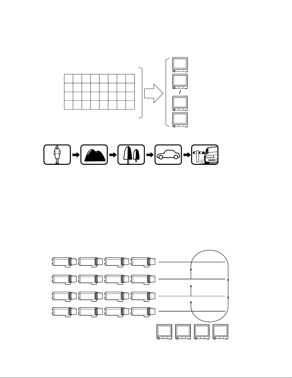
6. Sequence
This system has two kinds of sequential modes: Tour
and Group
6-1. Tour Sequence (T-SEQ)
A Tour Sequence consists of thirty-two (32) steps.
Each step has a Camera, Dwell Time and Auxiliary
Control or Pan/Tilt Preset assigned to it.
A total of thirty-two (32) Tour Sequences can be programmed on the T-SEQ setup tables.
A Tour can be assigned to any monitor.
• Auto Skip Function
The Auto Skip function is available in sequence
mode. If there is no video signal present at a step,
the sequence will automatically skip that step.
This function is enabled from programming the
Setup Menu.
-9-
• DWELL Time
The amount of time for each camera view is displayed on the monitor (Dwell Time) can be set from one (1) second to
thirty (30) seconds in 1-second increments.
This function is set from programming the Setup Menu.
External Timing, which is controlled from the Time Lapse VTR, can also be selected from programming the Setup Menu.
6-2. Group Sequence (G-SEQ)
A Group Sequence consists of up to thirty-two (32) steps.
In each step, a maximum of eight (8) cameras can be assigned to eight (8) monitors.
Pan/Tilt preset or Auxiliary control (1 & 2) can also be set for each camera/monitor combination.
Camera view switching (Dwell Time) for each step can be set from one (1) second to thirty (30) seconds in 1-second increments.
There are four (4) Group Sequences available, with programming performed on the G-SEQ Setup Tables.
T1 T2 T3 T4 T5 T6 T7 T8
T9 T10 T11 T12 T13 T14 T15 T16
T17 T18 T19 T20 T21 T22 T23 T24
T25 T26 T27 T28 T29 T30 T31 T32
Tour Sequence
32 Tours In Any Monitor
Monitor 1
Monitor 1
Dwell time: 5 sec.
Step 1
Monitor 1
Dwell time: 3 sec.
Step 2
Monitor 1
Dwell time: 10 sec.
Step 3
Monitor 1
Dwell time: 5 sec.
Step 4
Monitor 1
Dwell time: 3 sec.
Step 5
Monitor 2
Monitor 7
Monitor 8
CAM 13 CAM 14 CAM 15 CAM 16
CAM 9 CAM 10 CAM 11 CAM 12
CAM 5 CAM 6 CAM 7 CAM 8
CAM 1
Monitor 4
CAM 2 CAM 3 CAM 4
4th Floor
Group Sequence
C 16C 15C 14C 13
3rd Floor
C 12C 11C 10C 9
2nd Floor
C 8C 7C 6C 5
1st Floor
C 4C 3C 2C 1
Monitor 3Monitor 2Monitor 1
-10-
A
1
A
2 3 4
5 6 7 8
Alarm
C
1 2 3 4
5 6 7 8
A
Alarm
C
Alarm
B
Alarm
B
A
7. Timer
The timer function is used to programme and automatically activate Tour or Group Sequences according to
the time of day and day of the week.
There are sixteen (16) timers available in one day.
8. Alarm
8-1. Alarm Input
1. Camera Site Alarm
This alarm signal is supplied from the associated
camera site receiver or camera.
Receivers capable of camera site alarm input are
models WV-RC100, WV-RC150 and WV-RC170.
2. Interface Alarm
This alarm signal is supplied from the Alarm Input
Connector (ALARM IN) on the rear of the Switcher.
Up to thirty-two (32) alarm inputs are available.
3. Video Input Signal Loss Alarm
This alarm is indicated that camera signal loss has
occurred.
4. PC Command Alarm
This alarm is the received command from the
Personal Computer.
8-2. Alarm Operation Mode
There are three alarm operation modes available in the
WJ-SX350 Matrix Switcher.
The alarm modes can be switched according to the
time programmed on the internal timer.
Examples of these modes are given below.
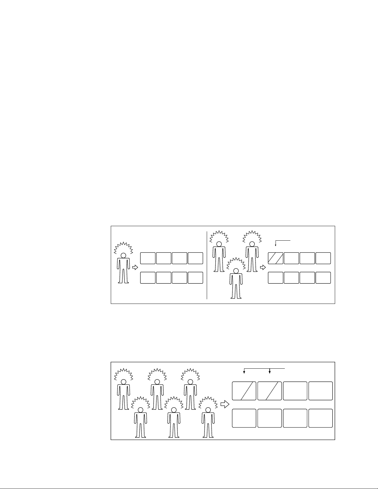
Alarm Mode 1: Any alarmed pictures are assigned to Monitor 1.
Mode 1 displays all alarms on Monitor 1.
If more than one alarm is activated, the system will sequentially display the alarms on Monitor 1.
Alarm Mode 2: Any alarmed pictures are assigned to four Monitors (1 - 4).
Mode 2 displays the first alarm on Monitor 1. When the second alarm is received, the first alarm is shifted to Monitor 2
and the second alarm is displayed on Monitor 1 and so on. This means, the latest alarm is always displayed on Monitor
1. If more than four alarms are activated, the system will sequence the pictures starting with Monitor 1, then 2, etc.
A
Alarm
F
1 2 3 4
5 6 7 8
B
Alarm
B
C
Alarm
E
Alarm
D
Alarm
F
Alarm
E
A
DC
Monitors
Sequence
Monitors
Sequence
-11-
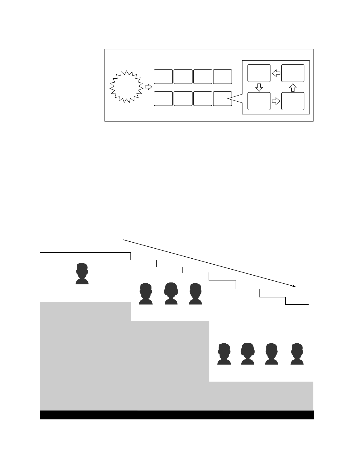
Alarm Mode 3: Any alarmed pictures are assigned to any monitors.
Mode 3 is a fully programmable mode. Any alarm can be shown on any monitor, plus sequence routines, presets and
auxiliary relays in receivers can be activated.
1 2 3 4
5 6 78
ANY
Alarm
WZ
XY
8-3. Alarm Recall
The WJ-SX350 Matrix Switcher can store up to ninety-nine (99) Alarm Events in its memory.
The alarms may be recalled and displayed in chronological order on any desired monitor.
9. Operator Registration (REGISTRATION)
On the Operator Registration tables, an operator's level, priority, password and camera access limits can be programmed.
Up to fifteen (15) operators may be registered.
For example:
34341 32213 3221332132
Level 3
12123
Level 1
Operator 1
1
12341 1244312243
Level 2
Operator 2 Operator 3 Operator 4
Operator 5 Operator 6 Operator 7 Operator 8
Priority
2
3
4
5
6
7
8
OPERATOR'S LEVEL TABLE
SETUP MENU
CAMERA TITLE
TIMER
TOUR SEQ
GROUP SEQ
PRESET
ALARM
CONTROLLER
OPERATOR
CLOCK
CAMERA SELECT
T-SEQ SELECT
G-SEQ SELECT
ALARM ACK/RESET
SETUP MENU
CAMERA TITLE
TOUR SEQ
GROUP SEQ
PRESET
ALARM
CONTROLLER
CAMERA SELECT
T-SEQ SELECT
G-SEQ SELECT
ALARM ACK/RESET
CAMERA SELECT
T-SEQ SELECT
G-SEQ SELECT

-12-
9-1. Level Setting
Operator access to various setup functions and system
operations is determined by the operator's level.
There are three (3) separate levels available (Level 1 is
the highest).
9-2. Priority Setting
When two or more operators attempt to perform the
same function at the same time, the operator with the
highest priority is allowed to perform the function while
the lower priority operators’ attempts are denied.
There are eight (8) priority levels available in this system.
9-3. Password
All operators have a five digit long password assigned
to them.
9-4. Operator Limits for Camera Access
Access to any camera’s video and control of the camera’s pan/tilt head may be restricted to certain operators.
7.MAY.98 12:34:56 AL1
/T16
C32 M2 CU3 3RD FLOOR
P64 T32 ROOM 306
wq
r
u
o
e
q Date and Time
w Alarm On/Off
AL0: Camera Site Alarm
AL1: Interface Alarm
AL2: PC Command Alarm
AL3: Video Input Signal Loss Alarm
e Timer Mode
r Camera Number
t Monitor Number
y Controller Number of associated controller
u Preset Position Number
i Sequence Mode in Effect
o Camera Title
10. Camera Title
Camera titles are available for each camera input.
Each title is composed of fifteen (15) characters per
line, times two (2) lines.
1 1. On-Screen Display
All items listed below, except Alarm On/Off and Timer
Mode, can be included or excluded from display on the
selected monitor screen:
Note: When the overscanning mode is selected on a
monitor, the screen display (edge portion) may be
partially hidden.
SITE STATUS
SHUTTER :
SENS UP :
PAN MODE :
CAMERA :
DEF :
WIPER :
AUX 1 :
AUX 2 :
C01 M1
12. Site Status Display
The selected camera status can be displayed on the
selected monitor screen.
-13-
S Y S T E M S T A T U S
< < M
CAM
M O D E C U
OPE PRI > >
A M1 0 1 T 0 5
CU
1 0 1 2
M2 0 9 S P
CU
2 0 2 2
M3 1 1 S P
CU
1 0 0 1 9
M4 1 2 G 1
CU
4 0 3 2
M5 0 5 S T A Y T U S
CU
4 0 4 5
M6 2 5 G 1 8
M7 1 0 S E T U P P C 1 6 1
M8 3 2 T 0 5 P
CU
0 0 5 3
13. System Status Display
q Monitor Number
w Camera Number
e Activated Mode
r Controller Number
t Operator Number
y Priority Number
123 4
M1 M2 M3 M4 M5 M6 M7 M8
System Controller Partitioning To Monitors
L
CLOSE
OPEN
IRIS
R
UP
DOWN
NEAR
FAR
FOCUS
BUSY
TELE
WIDE
ZOOM
0
987
654
321
ALARM MONITOR CAMERALOCKPOWER PROHIBITED
CAMERA SITE CONTROL
L
CLOSE
OPEN
IRIS
R
UP
DOWN
NEAR
FAR
FOCUS
BUSY
TELE
WIDE
ZOOM
0
987
654
321
ALARM MONITOR CAMERALOCKPOWER PROHIBITED
CAMERA SITE CONTROL
L
CLOSE
OPEN
IRIS
R
UP
DOWN
NEAR
FAR
FOCUS
BUSY
TELE
WIDE
ZOOM
0
987
654
321
ALARM MONITOR CAMERALOCKPOWER PROHIBITED
CAMERA SITE CONTROL
L
CLOSE
OPEN
IRIS
R
UP
DOWN
NEAR
FAR
FOCUS
BUSY
TELE
WIDE
ZOOM
0
987
654
321
ALARM MONITOR CAMERALOCKPOWER PROHIBITED
CAMERA SITE CONTROL
14. System Controller-Monitor Partitioning
This feature is used to prevent specific System Controllers from controlling the outputs of specific monitors.
It prevents an operator from unintentionally gaining control over a monitor that may not be associated with his/her station.
This table shows the system status in real time.
Possible Active modes, as indicated in this table, are
defined below.
A : Alarmed
SP : Spot
TMM : Tour Sequence
GMM : Group Sequence
P : Paused Sequence
CAMERA : Camera Setup
SETUP : System Setup
RECALL : Alarm Recall Display
STATUS : System Status Display
Note: The sequence number is inversely displayed on
the table when a sequence runs in the reverse
direction.
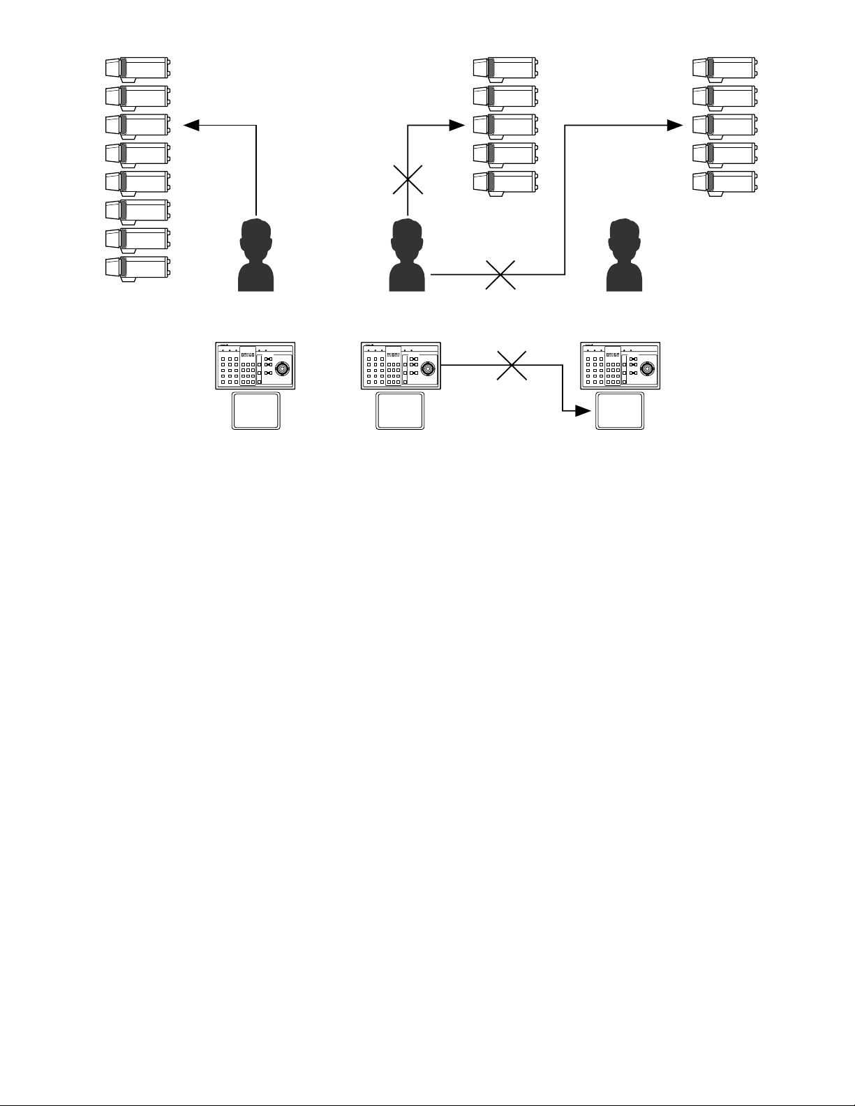
For example:
The following example demonstrates the use of
both system controller-monitor partitioning and
operator priority.
• Camera: 8 sets
• Monitor: 3 sets
• System Controller: 3 sets
• Operator: 3 persons
Setting Procedure
1. Operator Number 1 has the first priority. Cameras 1
- 8 can be selected by Monitor 1.
2. Operator Number 2 has the second priority.
Cameras 1-5 can be selected by Monitor 2 (limited
access due to operator partitioning).
3. Operator Number 3 also has the second priority.
Cameras 4 - 8 can be selected by Monitor 3.
-14-
1
M1
SPOT
Controller 1
Operator 1
Priority 1
M2
SPOT
Controller 2
Operator 2
Priority 2
M3
SPOT
Controller 3
Operator 3
Priority 2
Controller
Partitioning
Operator's
Partitioning
Operator's
Priority
2
3
4
5
1
2
3
4
5
4
5
6
7
8
6
7
8
L
CLOSE
OPEN
IRIS
R
UP
DOWN
NEAR
FAR
FOCUS
BUSY
TELE
WIDE
ZOOM
0
987
654
321
ALARM MONITOR CAMERALOCKPOWER PROHIBITED
CAMERA SITE CONTROL
L
CLOSE
OPEN
IRIS
R
UP
DOWN
NEAR
FAR
FOCUS
BUSY
TELE
WIDE
ZOOM
0
987
654
321
ALARM MONITOR CAMERALOCKPOWER PROHIBITED
CAMERA SITE CONTROL
L
CLOSE
OPEN
IRIS
R
UP
DOWN
NEAR
FAR
FOCUS
BUSY
TELE
WIDE
ZOOM
0
987
654
321
ALARM MONITOR CAMERALOCKPOWER PROHIBITED
CAMERA SITE CONTROL
1. In the above system, when Operators 1 and 2 both
select camera 3 simultaneously, the selection of
Operator 1 is allowed because Operator 1 has a
higher priority.
2. Operator 2 cannot select camera 6 because operator's partitioning limits access to cameras 1 - 5 by
Operator 2.
3. Operator 2 cannot control Monitor 3 because controller partitioning prevents access to Monitor 3 by
Operator 2.
15. Synchronizing the Sequence with External Timing
The camera switching interval (Sequence Dwell Time)
can be synchronized with the time lapse mode set in the
associated Time Lapse VTR.
Select the On or Off mode to meet each monitor’s
requirements on the EXT TIMING setup table.
Caution: Set the interval time for the external timing sig-
nal of the external equipment to one (1) second or
more.
If the interval is set to less than one (1) second, the
system will not work properly.
16. RS-485 Site Communication
The parameters for communication with the Camera Site
can be set on the RS485 CAM COM. setup table.
Usually, the Baud Rate is set to 9,600 bps, with a Wait
Time of 100 ms.
(The WV-RM70 Camera Controller or a modem may be
required in the system.)
Note: Be sure to select the correct Baud Rate when
using a modem.
17. Clock
On-screen clock display is available.
The date and time can be set on the CLOCK SET setup
table.
18. RS-232C Port
This port is used for connecting with a Personal
Computer. The memory of the WJ-SX350 Matrix
Switcher can be loaded or saved.
Also, a Personal Computer can be substituted for the
Switcher to control the system.
Note: For using a Personal Computer, you will need
special software offered separately.

-15-
SECTION 2
DETAILED
PRODUCT
DESCRIPTION
-16-
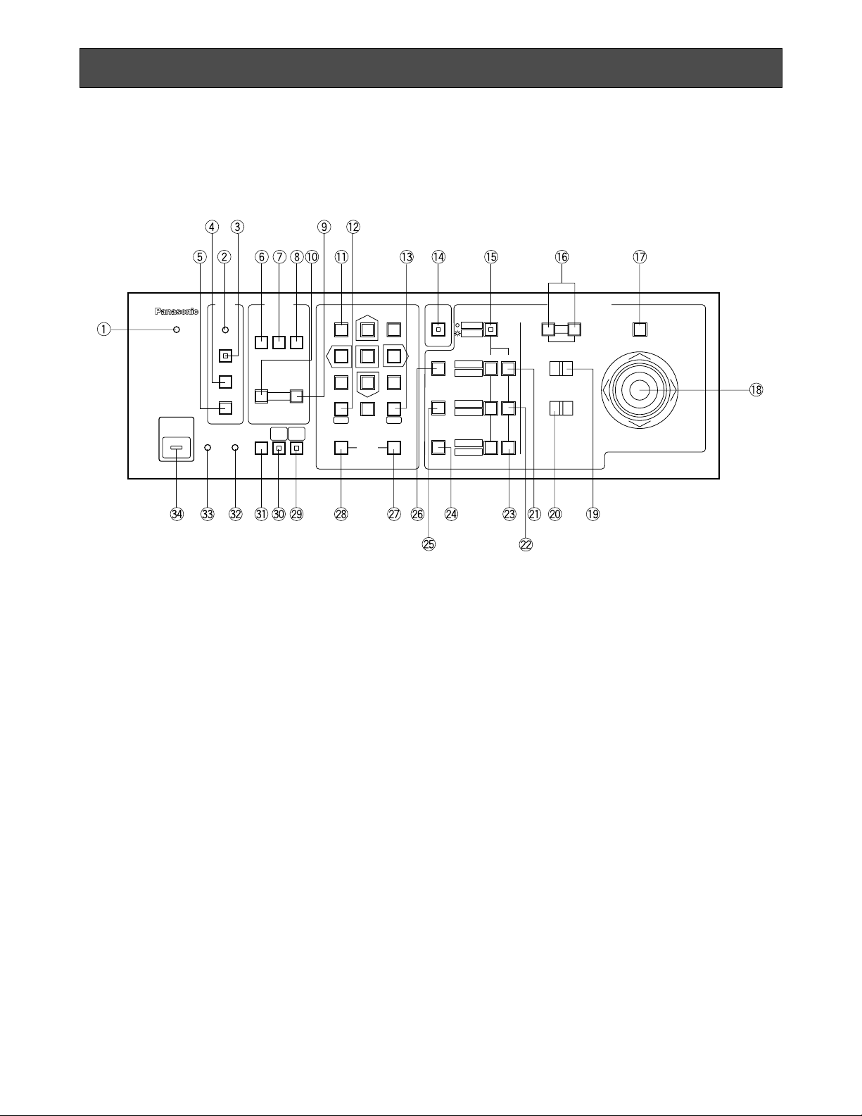
1. Log-in indicator (LOGIN)
This indicator lights up when log-in is accomplished.
2. Alarm indicator (ALARM)
This indicator blinks to indicate an alarm condition
exists.
It changes to steady light when the alarm is reset
automatically.
To turn off the indicator, press the ACK/RESET or
ALL RESET button.
3. Alarm Acknowledgment and Reset button
(ACK/RESET)
This button is used to cancel the activated alarm.
You must select the alarmed monitor(s) first to cancel the alarm.
Press this button once to acknowledge the activated alarm (the indicator blinks rapidly), then press
this button once again for alarm reset.
4. All Alarms Reset button (ALL RESET)
This button is used to cancel plural alarms in a
lump.
Select the alarmed monitor first (Monitor 1 for Alarm
Mode 1, one of four monitors for Alarm Mode 2),
then press this button for alarm reset.
MAJOR OPERATING CONTROLS AND THEIR FUNCTIONS
<Front View>
5. Alarm Recall button (RECALL)
This button is used to recall the Alarm Logs
(Activated alarm records).
Select the desired monitor to display the alarm
records, then press this button to toggle the display
of alarm records On and Off on the selected monitor.
6. Backward Sequence button (BACK SEQ)
This button, in combination with the Numeric buttons, is used to run a Tour or Group sequence in
reverse on the selected monitor.
It is also used to continue a sequence in reverse,
that was previously paused on that monitor by the
PAUSE button.
7. Sequence Pause button (PAUSE)
This button is used to pause a sequence that is
being run on the selected monitor.
8. Forward Sequence button (FWD SEQ)
This button, in combination with the Numeric buttons, is used to run a Tour or Group sequence in
forward on the selected monitor.
It is also it is used to continue a sequence forward,
that was previously paused on that monitor by
pressing the PAUSE button.
LOGIN
BUSY
PROHIBITED STATUS
ALARM
ALARM
SEQUENCE
ACK/RESET
OPERATE
ALL RESET
RECALL
CAM
MENU
SET UP
PAUSE
BACK
SEQ
FWD
SEQ
−1 CAM
DEC
+1 CAM
INC
321
654
987
FWD
ALT SHIFT
AUTO FOCUS
FUNCTION
ON OFF
PRESET
POSI
CAM
POSI
BACK
CAM
0
MON
SETESC
HISTORY
AUTO PAN
RANDM PAN
AUX 1
WIPER
AUX 2
DEF
IRIS
CLOSE
NEAR FAR
OPEN
IRIS RESET
FOCUS
TELE WIDE
LEFT RIGHT
UP
DOWN
ZOOM
MATRIX SWITCHER WJ-SX350
CAMERA SITE CONTROL

-17-
9. Increment button (+1CAM INC)
This button is used to move a sequence one step
forward from the step that was previously paused
on the selected monitor by pressing the PAUSE
button.
Also, when the selected monitor is in the spot
mode, pressing this button will replace the selected
camera with the next higher camera number.
10. Decrement button (–1CAM DEC)
This button is used to move a sequence one step
backward from the step that was previously
paused on a monitor by pressing the PAUSE button.
Also, when a selected monitor is in the spot mode,
pressing this button will replace the currently
selected camera with the next lower camera number.
11. Numeric buttons (0-9)
These buttons are used for numerical input into the
system such as the camera and monitor selection,
sequence and preset position, etc.
12. Monitor/Escape button [MON (ESC)]
MON: This button is used for monitor selection.
Press the desired Numeric buttons, then press
this button to select the monitor.
ESC: This button is used to escape and execute
the currently highlighted setting on the SETUP
MENU of the Matrix Switcher.
13. Camera/Set button [CAM (SET)]
CAM: This button is used for camera selection.
Press the desired Numeric buttons, then press
this button to select the camera.
SET: This button is used to execute the currently
highlighted setting on the SETUP MENU of the
Matrix Switcher.
14. Alternate button (ALT)
This button alternates the original function on twofunction control buttons with another function, or
prepares the CAM MENU button and SET UP button to display the assigned menu or setup table on
the selected monitor.
15. Shift button (SHIFT)
This button toggles six functions that are assigned
to three On and Off button groups (two functions
are assigned to each button group).
16. Iris Control buttons (IRIS)
These buttons are used to close or open the lens
iris of cameras equipped with the specified lens.
When these buttons are pressed at the same time,
the lens iris is reset to the factory setting.
17. Auto Focus button (AUTO FOCUS)
This button is used to activate the auto focus function, when the specified camera, such as the WVCSR600 series, is used.
18. Joystick Controller (UP/DOWN/LEFT/RIGHT)
This controller is used to operate the Pan/Tilt Head
manually, or to move the cursor to the desired position on the setup menu of the Matrix Switcher.
UP: Upward.
DOWN: Downward.
LEFT: Left.
RIGHT: Right.
19. Focus switch (FOCUS NEAR / FAR)
This switch is used to adjust the lens focus of cameras equipped with the specified lens.
20. Zoom switch (ZOOM TELE / WIDE)
This switch is used for zooming cameras equipped
with the specified lens.
21. ON and OFF buttons for AUTO PAN/RANDM
PAN
These buttons are used to turn On and Off the two
camera functions that can be alternated by the
SHIFT button.
When SHIFT is in Off position, these buttons turn
Auto Panning (AUTO PAN) On and Off.
When SHIFT is in On position, these buttons turn
Random Panning (RANDM PAN) On and Off.
22. ON and OFF buttons for AUX1/WIPER
These buttons are used to turn On and Off the two
camera functions that can be alternated by the
SHIFT button.
When SHIFT is in Off position, these buttons turn
the Auxiliary 1 (AUX 1) switch On and Off.
When SHIFT is in On position, these buttons turn
the wiper (WIPER) switch On and Off.
23. ON and OFF buttons for AUX2/DEF
These buttons are used to turn On and Off the two
functions that can be alternated by the SHIFT button.
When SHIFT is in Off position, these buttons turn
the Auxiliary 2 (AUX 2) switch On and Off.
When SHIFT is in On position, these buttons turn
the defroster (DEF) switch On and Off.
24. Camera Position button (CAM POSI)
This button, in combination with the Numeric buttons, is used to move the camera to the desired
camera position.
25. Preset Position button (PRESET POSI)
This button, in combination with the Numeric buttons, is used to move the camera to the desired
preset position.
26. Function button (FUNCTION)
Pressing this button in combination with another
operation button activates a specific function.
27. History Forward button (HISTORY FWD)
This button is used to move the camera picture forward on the selected monitor after the HISTORY
BACK button has been used.
This button also selects the next page or step of
the setup tables on the SETUP MENU.
-18-
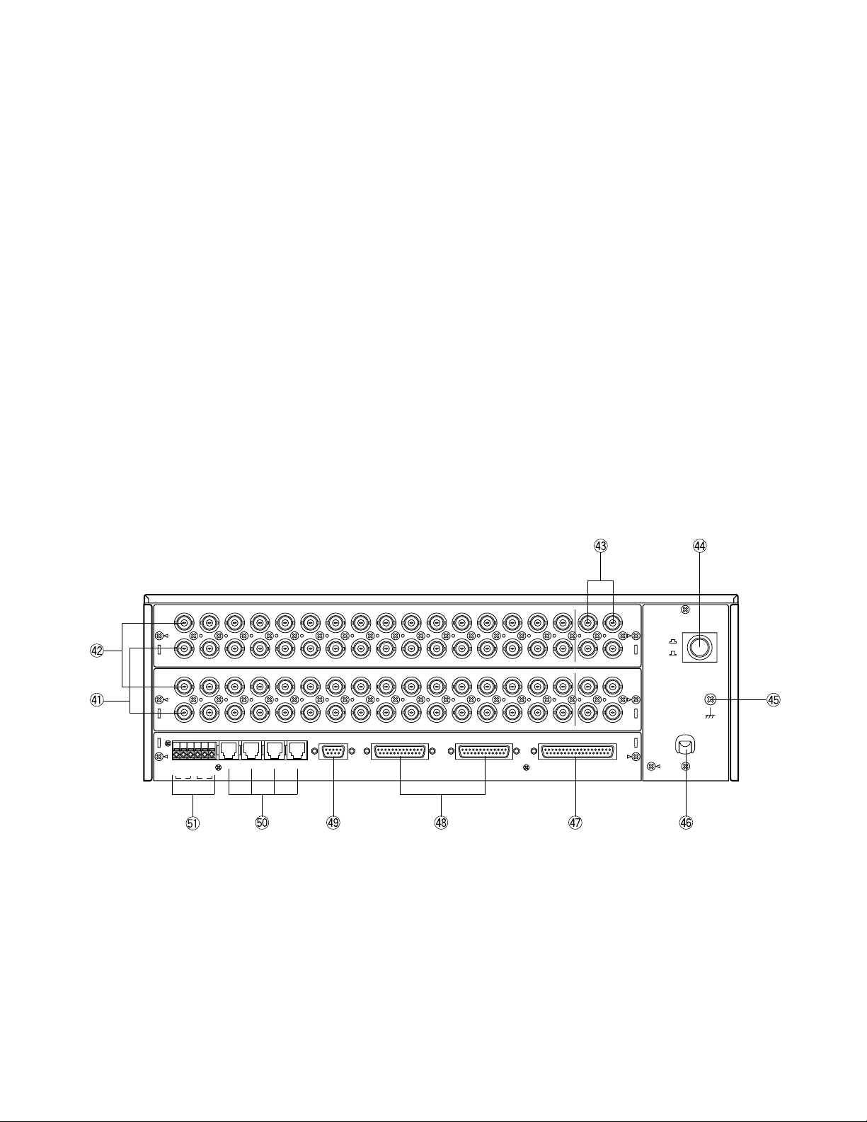
<Rear View>
OFF
ON
POWER
SIGNAL
GND
1
3
2
4
112
2
3
3
4
4
5566778
8
9
9
10
10
11
11
12
12
13
13
14
14
15
15
16
16
MONITOR OUTCAMERA IN
5
7
6
8
17
17
18
18
19
19
20
20
21
21
22
22
23
23
24
24
25
25
26
26
27
27
28
28
29
29
30
30
31
31
32
32
MONITOR OUTCAMERA IN
ALARM OUT 5-8 ALARM OUT 1-4 ALARM INRS-232CDATA INRS485
1234G
N
D
B A G
N
D
B A
2 1
32. Prohibited LED indicator (PROHIBITED)
This indicator lights up for two seconds when the
incorrect operator number or password is selected
to Log-in.
This indicator also blinks when an attempt is made
to gain access to a function that is prohibited by the
operator's level.
33. Busy LED indicator (BUSY)
This indicator blinks (or lights up) when you attempt
to control a certain monitor (or a camera) that is
already used by a higher priority operator, or when
the higher priority operator chose the camera or
monitor you are currently operating.
Blink: Monitor
Light up: Camera
34. Operate LED indicator (OPERATE)
This indicator is lit while the Switcher’s power is
turned on.
28. History Back button (HISTORY BACK)
This button is used to display the previous camera
picture on the selected monitor. Each operation of
this button backs up the camera picture by ones.
This button also selects the previous page or step
of the setup tables on the SETUP MENU.
29. Set Up button (SET UP)
This button, in combination with the ALT button, is
used to display the SETUP MENU of the Matrix
Switcher.
30. Camera Menu button (CAM MENU)
This button, in combination with the ALT button, is
used to display the selected Camera’s SetUp Menu.
31. Status button (STATUS)
This button toggles the display of the Camera Site
Status Table On and Off on the selected monitor.
Note: In combination with the ALT button, this but-
ton toggles the display of the System Status
Table On and Off on the selected monitor.
-19-
49. RS-232C Port (RS-232C)
This port is used to connect a Personal Computer to
control the Switcher remotely.
50. Data Ports (DATA IN)
These ports are used to exchange control data with
the System Controllers specified for the system.
51. RS485 Terminal (RS485)
This terminal is used to exchange control data with
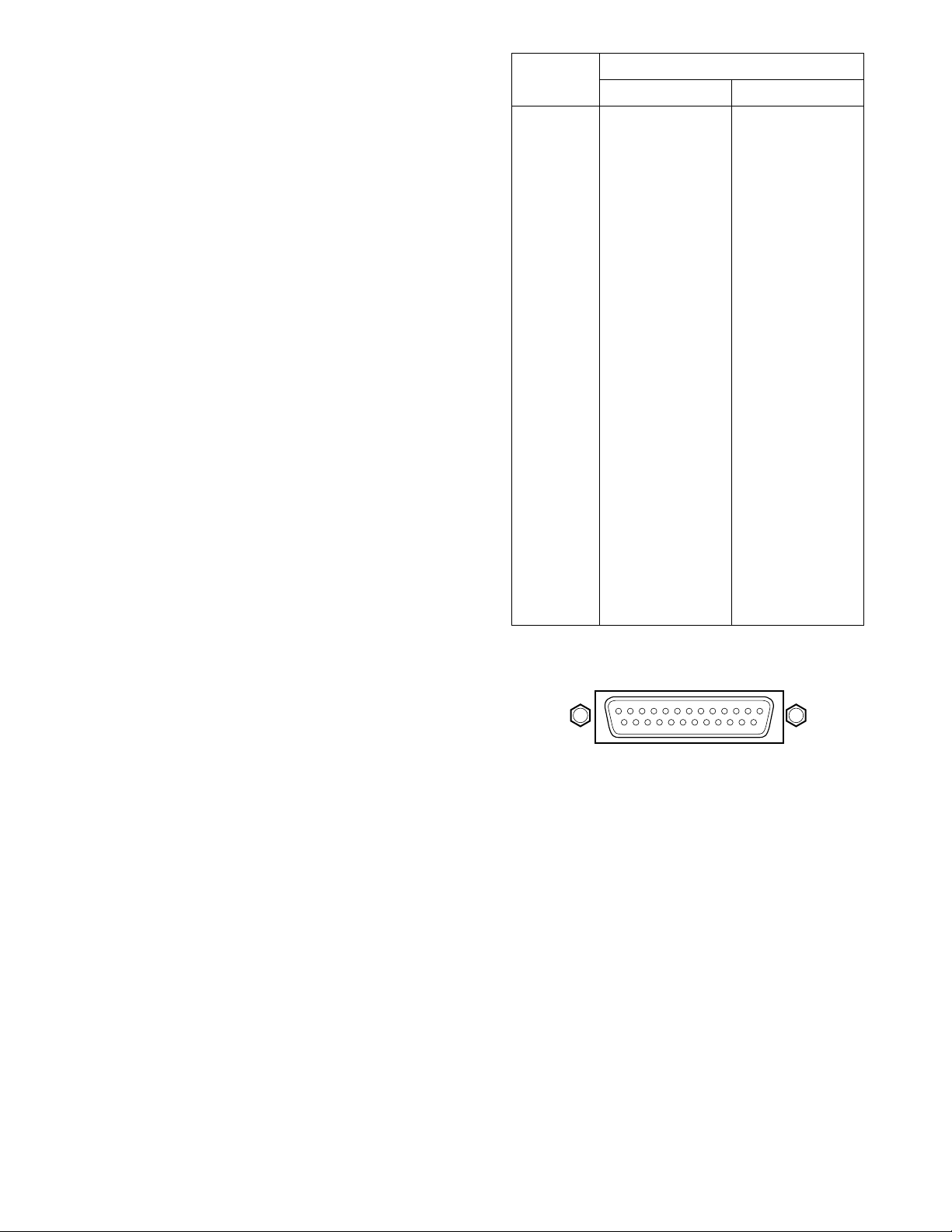
the camera site equipment.
Pin Number
1
2
3
4
5
6
7
8
9
10
11
12
13
14
15
16
17
18
19
20
21
22
23
24
25
ALARM OUT 1
RESET OUT 1
RECOVER IN 1
Ground
EXT TIMING IN 1
Ground
ALARM OUT 2
RESET OUT 2
RECOVER IN 2
Ground
EXT TIMING IN 2
Not used
ALARM OUT 3
RESET OUT 3
RECOVER IN 3
Ground
EXT TIMING IN 3
Ground
ALARM OUT 4
RESET OUT 4
RECOVER IN 4
Ground
EXT TIMING IN 4
Ground
Ground
ALARM OUT 5
RESET OUT 5
RECOVER IN 5
Ground
EXT TIMING IN 5
Ground
ALARM OUT 6
RESET OUT 6
RECOVER IN 6
Ground
EXT TIMING IN 6
Not used
ALARM OUT 7
RESET OUT 7
RECOVER IN 7
Ground
EXT TIMING IN 7
Ground
ALARM OUT 8
RESET OUT 8
RECOVER IN 8
Ground
EXT TIMING IN 8
Ground
Ground
Designation
ALARM OUT 1-4 ALARM OUT 5-8
13 1
1425
41. Camera Output Connector (CAMERA OUT)
The video signal connected to the Camera Input
Connector (CAMERA IN) is looped through to this
connector with an automatic 75Ω termination.
42. Camera Input Connector (CAMERA IN)
This connector accepts either a colour or B/W composite video signal from a camera.
43. Monitor Output Connector (MONITOR OUT)
The video signal selected on the Matrix Switcher is
supplied to the Video Monitor from this connector.
44. Power Switch (POWER ON / OFF)
This switch is used to turn the Matrix Switcher
power On or Off.
45. Signal Ground Terminal (SIGNAL GND)
46. Power Cord
47. Alarm Input Port (ALARM IN)
This port accepts alarm signals from the associated
alarm sensor.
The Input Load Capacitance of each alarm input is
required less than 0.01µF.
48. Alarm Control Ports (ALARM OUT 1-4, 5-8)
These ports are used to control the system as follows:
Alarm Output (ALARM OUT):
When the Matrix Switcher receives an alarm
from the ALARM IN port or Camera Site, this
connector provides the alarm output signal for
the Time Lapse VTR.
Reset Output (RESET OUT):
When the Matrix Switcher resets the activated
alarm, this connector provides the alarm reset
output signal for the Time Lapse VTR.
Recover Input (RECOVER IN):
This connector accepts the alarm recover signals from the Time Lapse VTR.
External Timing Input (EXT TIMING IN):
The camera switching interval (Sequential Dwell
Time) can be synchronized with the lapse
mode set on the Time Lapse VTR.
EXT TIMING IN 1 controls Monitor 1 output, EXT
TIMING IN 2 controls Monitor 2 output, etc.
The camera switching pulse from the Time
Lapse VTR is supplied to the Switcher through
this connector.
 Loading...