

Page 1
Matrix Switcher
WJ-SX150A
Matrix System150
Version 2.0
System Controller
WV-CU650
Page 2
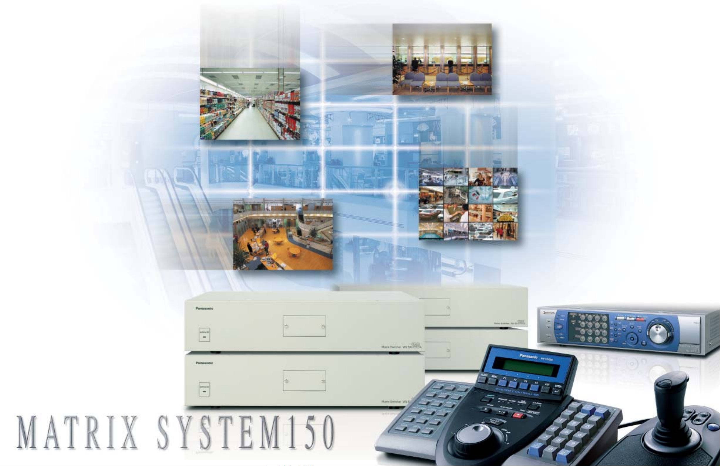
Controls up to 64*cameras and 4 monitors.
The Matrix System150 is compact,
high in quality and cost effective.
The new Panasonic Matrix System150 is ideal
for small-scale surveillance applications. The
Matrix Switcher can link up to 64 cameras,
4 monitors and 4 controllers. It can be
combined with our dome cameras providing
excellent image quality.
All of the Matrix System150’s 64 channels
employ Panasonic proprietary coaxial,
multiplex connectors. Video signals, control
data, synchronous signals (VD2) and alarm
signals all travel over a single cable, reducing
the number of lines required for camera
installation. Cables can be as long as 900 m
(3,000 feet). This System also supports remote
camera control using RS-485 data.
The Matrix System150 is loaded with special
features including tour sequencing, alarms,
video loss detection, and character displays on
the monitor. All features are easy to operate
using the WV-CU650 dedicated system
controller.
One major feature is the ease of changing
system settings using menus displayed on a
personal computer. Providing direct control of
all device settings as well as user management
features, the system administration software
bundled with the Matrix System150 imposes
no extra burden on system administrators.
Access to vital settings data can be restricted
to a specified level of user through use of User
ID (operator number) and passwords.
Major Features and Functions
Camera
• Supports up to 64 cameras.
• All 64 channels are coaxial, multiplex cables,
reducing the number of cables required and
simplifying installation.
• Supports up to 64 RS-485, remote-controlled
cameras.
• Pan, tilt and other cameras lens motions can be
controlled either by coaxial, multiplex cable or
RS-485 remote-control signals.
• Cables can be up to 900 m (3,000 feet) long.
• The video loss detection function automatically
detects camera malfunctions.
System
• All sequence and alarm modes can be adjusted
as needed.
• User management features include operator
number, password, level, and priority.
• Personal computer screen displays simplify setup and management of alarm histories.
• Supports up to 80 alarm inputs and four alarm
outputs.
Monitor
• Output supports up to 4 monitors.
• Character displays show date, time, camera
number, camera title, and event information.
• Alarm history display shows up to 100 most
recent alarms.
External Links
• The RS-485 camera ports allow remote
surveillance.
• The RS232C ports enable connection to
personal computers or VCRs.
The above all photographs were taken for the purpose of explanation; actual images may differ.
The Matrix System150 is ideal for schools,
supermarkets, banks, parking lots, warehouses,
and correctional facilities. The Matrix
System150’s small-scale system simplifies
operation while providing all the features
required for high-level surveillance.
*When cascade configuration
2 3
Page 3

step 1
Tour 1
C1
Tour 2
C5
Tour 3
C9
Tour 32
C13
step 2
C2
C6
C10
C14
step 3
C3
C7
C11
C15
step 64
C16
C4
C8
C12
The image shifts automatically from one camera to another, as programmed.
The images can
be seen on any
monitor.
Group sequence 1
Monitor 1
Tour 1
C1
Monitor 2
Tour 5
C20
Monitor 3
Tour 2
C5
Monitor 4
Tour 7
C15
Group sequence 2
Group sequence 3
Group sequence 4
Timing Pulse (VD2) for Vertical Genlock
Camera to Matrix Switcher
Matrix Switcher to Camera
Data 8-bit x 4
Alarm
Video
Vertical Blanking
CH 1
ALARM 01
CH 8
ALARM 08
CH 5
ALARM 05
CH 1
ALARM 01
CH 1
ALARM 01
T-SEQ 1
ALARM 01
Sequencing and Alarm. Just Two of Many Features that Support Effective Surveillance.
WV-CU650 WJ-SX150A
Sequencing Increases Monitoring Efficiency
Sequencing Increases Monitoring Efficiency
Pre-set the sequence in which to view an image from a series of different cameras. The WV-CU650 System Controller
makes it possible to choose from a variety of sequence patterns with push-button ease. Just select the one that provides
the most effective coverage.
Tour Sequence
The monitor switches automatically, following a pre-set sequence from
channel 1 to channel 64. Each sequence can include up to 64 steps,
with each step set from one to 30 seconds in length. In addition, dome
cameras can also be pre-set to precisely the viewing angle you need.
Up to 32 touring patterns can be stored in memory for easy recall.
Group Sequence
This feature allows you to activate multiple, pre-set tour sequences by
pushing a single button. Each group can include up to four tour
sequences. Up to four group sequences can be stored in memory.
(Simultaneous tour sequencing)
64 Channels are All Transmitted via the Same Coaxial Cable
64 Channels are All Transmitted via the Same Coaxial Cable
Video signals, control data, synchronous signals (VD2), and alarm signals are all transmitted over the same coaxial,
multiplex cable. Use of the same cable reduces both time and trouble required for camera installation. Each coaxial cable
can be up to 900 m (3,000 feet) long.
1. Video signal
Transmits the image captured by the camera to the
Matrix Switcher.
2. Control data
Transmits settings from the Matrix Switcher to the camera.
Allows control of pan, tilt and zoom features of WV-CW864A/
WV-CS954/ WV-CS574 intelligent dome cameras, and via
WV-RC100/WV-RC150 remote control receivers,
WV-CL920A/WV-CP480/WV-CP240 Series.
VD2 Compatible Panasonic Camera List
B/W Cameras WV-BP330 Series, WV-BP140 Series
Color Cameras WV-CW474A Series, WV-CW244 Series, WV-CF224,
WV-CF212, WV-CW374, WV-CL920A Series,
WV-CP480 Series, WV-CP254H, WV-CP240 Series
Integrated Dome Cameras WV-CW864A, WV-CS954, WV-CS574
Since 1988, most of Panasonic cameras have been designed and manufactured to accept VD2 signal for system integration.
3. Synchronous signals (VD2)
Supports almost all Panasonic CCD cameras (see compatible
camera list). Allows simultaneous image switching by
cameras and the Matrix Switcher, preventing image distortion.
4. Alarm signals
Transmits alarm signals received from the camera to the
Matrix Switcher, initiating the pre-set alarm event sequence.
User Management Protects Against Misuse
Instant No-Escape Alarms
Instant No-Escape Alarms
User Management Protects Against Misuse
This system manages user names and other user information for
Sequence mode (In response to spot alarm)
Monitor 1: Alarm 1 received
from Camera 1.
Monitor1: Alarms are received sequentially
from Alarm 1 (Camera 1) to Alarm 8 (Camera 8).
When the alarm signal is received, the monitor and camera
instantly switch to the spot from which it originates. When two
or more alarms are received, the system switches instantly to
the spot from which the latest alarm originates. Pressing the
ACK key switches operator control to the camera from which
the alarm was received.
Hold mode (In response to spot alarm)
When the alarm signal is received, the monitor shows the
image from the pre-set camera. When two or more alarms are
Camera 1 shows spot where alarm originated.
Monitor 1: Alarm 1 received
from Camera 1.
CH 1
ALARM 01
Image shifts from Camera 8 to Camera 1.
Monitor1: Alarms are received sequentially
from Alarm 1 (Camera 1) to Alarm 8 (Camera 8).
received, the monitor continues to show the image of the spot
from which the first alarm was received. Pressing the ACK key
switches operator control to the camera from which the alarm
was received.
Concerning start of Sequence Alarm
Camera 1 shows spot where alarm originated.
Monitor 1: Alarm 1
(Tour Sequence 1)
Only the image from Camera 1 is seen. The * signal that appears
on the monitor indicates that additional alarms have been received.
The system can also be pre-set to start a tour sequence when
an alarm signal is received. However, once a sequence
begins, a second alarm cannot enter the monitor, as it can in
sequence or hold mode.
Most recent 100 alarms display
The monitor display shows up to 100 of the most recent
alarms in chronological order, allowing quick
confirmation of alarm location, date, and time. Images
can be recalled and reviewed with push button ease
using the WV-CU650 system controller.
4 5
Tour Sequence 1 starts automatically.
Alarm history management using
a personal computer
The alarm log can be output to a personal computer using
the RS232C serial port, allowing use of the personal
computer to manage alarm histories.
up to 16 users, who may use the controller itself or log in from a
personal computer. Matrix System150 operation can be limited
by use of five user attributes including operator number,
password, level, priority, and the cameras the user is permitted
to operate. This user management feature prevents improper
use by outsiders or unauthorized persons.
Operator Registration
OPE
1
12123
Level 1
SX150 Setup
Camera Setup
Indicate Alarm History
Indicate Video Loss History
Indicate System Status
One Alarm Reset
All Alarm Reset
Camera Cleaning
Select Camera
Start Sequence
Register Preset
Display OSD
Control Camera
Control Recorder
OPE2OPE3OPE4OPE5OPE
21233
6
25376
21325
Level 2
Indicate System Status
One Alarm Reset
All Alarm Reset
Camera Cleaning
Select Camera
Start Sequence
Register Preset
Display OSD
Control Camera
Control Recorder
24953
22342
OPERATOR’S LEVEL TABLE
Priority
Password
OPE7OPE8OPE9OPE10OPE11OPE12OPE13OPE14OPE15OPE
31256 34397
32356
34682
Display OSD
Control Camera
Control Recorder
31625
Level 3
39262
34645
37322
31828
16
39768
Other Convenient Features
Other Convenient Features
RS-485 Port
Up to 64 cameras can be controlled through the built-in RS-485 ports.
RS232C External Serial Interface
The RS232C port permits system set-up and alarm history
management from a personal computer. It also supports time-lapse VCR
and other peripherals.
Video Loss Detection automatically
senses camera malfunction
This feature automatically senses loss
of video signal input and displays a
warning on the monitor, allowing speedy
response to such problems as power
outage, severed camera cables or
damaged cameras.
Video Loss History Table
Monitor Character Displays
Four types of information are displayed on the monitor using the built-in
character generator IC.
1. Date and time
Choice of five date styles and 24-hour or 12-hour time displays.
2. Camera title
A label up to 20 characters long can
be added to the camera number.
3. Monitor status
Shows monitor number, keyboard
number, and sequence status.
4. Event information
Shows time and other information
concerning alarm or timed events.
The above all photographs were taken for the purpose of explanation; actual images may differ.
Example of Character Displays
Page 4

Front View
Rear View
Front View
Rear View
System Configuration is Simple and Trouble-Free.
480 (18-7/8")
420 (16-9/16")
465 (18-5/16") (Mounting Pitch)
350 (13-3/4")
270 (10-5/8")
40 (1-9/16")
88
(3-7/16")
98 (3-7/8")
76 (2")
(Mounting Pitch)
10
(3/8")
290 (11-7/16") 134 (5-1/4")
111 (4
-3/8"
)
2
.5
(1
/8
")
180 (7
-1/16"
)
194 (7
-5/8"
)
221 (8
-11/16"
)
218 (8-9/16")
1 (1/16")
146 (5-3/4")
64 (2-1/2")
CLEAR
OPERATE
ADJUST
MENU F1 F2 F3 F4 EXIT ENTER
ALARM
PLAY/PAUSE
SHUTTLE
HOLD
STOP
REV FWD
REC STOP
REC
A
L
A
R
M
A
L
M
R
E
S
E
T
A
C
K
A
L
M
S
U
S
P
E
N
D
A
L
M
A
L
L
R
E
S
E
T
O
S
D
C
A
M
F
U
N
C
ALM RECALL
SEQ PAUSE
MON LOCK
TOUR SEQ
M
U
L
T
I
S
C
R
E
E
N
GOTO LAST
EL-ZOOM
AUX1
ON
M
A
R
K
AUX2 ON
O
F
F
O
F
F
W
IP
E
R
S
E
A
R
C
H
D
E
F
O
N
O
F
F
T&D SEARCH
SEQ STOP
L
O
G
O
U
T
G
RO
UP SEQ
S
Y
S
F
U
N
C
1
3
P
R
E
V
R
E
C
O
R
D
E
R
PR
ESET
PGM
PRESET
C
A
M
P
O
S
I
C
A
M
(
S
E
T
)
M
O
N
(
E
S
C
)
U
N
I
T
2
4
6
5
7
9
8
0
ALM
SUSPEND
SHIFT
+–
SYSTEM CONTROLLER
WV-CU650
DC9V IN
MODE
DATA
SERIAL
CONTOROLLER
NO.
JOYSTICK
OPEN
IRIS
CLOSE
FAR
FOCUS
NEAR
A B
Time and date
Camera channel/
Recording event
Number of
listed data
MAJOR OPERATING CONTROLS
Matrix Switcher; WJ-SX150A
Simple System Setup from a PC
Simple System Setup from a PC
Main Menu
The main menu is the heart of the System150 Setup Utility.
Logical Camera Number
System Configuration Software is Included.
Tour Sequence
This window is used to edit a tour sequence. There
are 32 tour sequences available, each with up to 64
steps. Each step needs a camera number associated
pan/tilt preset position and a dwell time.
Timer Event
This window can be used to edit the time and type of
action.
Operator Registration
Group Sequence
This window is used to edit a group sequence. There are
4 group sequences available, each with up to 4 monitors.
Alarm Event
This menu can be used to program which monitor will
carry out the spot/tour sequence of a specific camera,
when an alarm signal is input.
Level Window
System Controller; WV-CU650
SPECIFICATIONS
Matrix Switcher; WJ-SX150A
Power Source 120 V AC, 60 Hz
Power Consumption 60 W
Camera Input (1 - 16) 1.0 V[p-p]/75 Ω composite video signal
Master - Slave
This window is used to
assign the camera control
to the operators, according
to their priorities.
This window is used to
restrict the operators'
control of functions
according to their levels.
Camera Output (1 - 16) 1.0 V[p-p]/75 Ω composite video signal
Monitor Output (1 - 4) 1.0 V[p-p]/75 Ω composite video signal
External Input 1.0 V[p-p]/75 Ω composite video signal
External Output 1.0 V[p-p]/75 Ω composite video signal
RS-485 (Camera) Port RS-485 6-conductor modular jack
Data Port RS-485 6-conductor modular jack
Alarm Port 25-pin D-sub connector
Serial Port 9-pin D-sub connector
Camera Switching Input RCA pin jack
Ambient Operating Temperature
Ambient Operating Humidity
Dimensions 420 mm (W) x 88 mm (H) x 350 mm (D) (without rubber foot)
Weight (approx.) 6 kg (13.2 lbs.)
Flexible and Compatible with a Wide Range of Equipment
Flexible and Compatible with a Wide Range of Equipment
The Matrix System150 can be connected to a WJ-HD300A Series Digital Disk
Recorders equipped with a high-capacity hard disk drive to construct a
Thumbnail
Display
featured-loaded system for long-duration recording of multiple types of highquality images. The Filtered Search function supports searches using multiple
date/time and camera channel criteria. The Playback VMD function instantly
identifies scenes with movement, making it
simple to find and playback critical scenes
buried in large amounts of image data. Search
results can be displayed as thumbnails.
6 7
WJ-HD316A Ensures
High-quality, Moire-free Images
The above all photographs were taken for the purpose of explanation; actual images may differ.
System Controller; WV-CU650 (for WJ-SX150A)
Power Source 9 V DC, 300 mA (using the supplied AC adapter)
Power Source (supplied AC adapter) 120 V AC, 60 Hz, 200 mA
Data Output/Input Port 6-conductor modular jack (RS-485, Full duplex) x2
Serial Port 9-pin D-sub connector
Controller Number 1 to 8 (rotary switch)
Ambient Operating Temperature –10 °C ~ +50 °C (14°F ~ 122 °F)
Monitor Number Selection 1 to 4
Camera Number Selection Up to 64
Dimensions (W x H x D) Main Unit:
Weight (without the AC adapter) Main Unit: 1.3 kg (2.86 lbs.)
0.5 V[p-p]/75 Ω data signal and
2.5 V[p-p]/75 Ω vertical timing pulse multiplexed
–10 °C ~ +50°C (14 °F ~ 122°F)
Less than 90 %
(16-9/16" (W) x 3-7/16" (H) x 13-3/4" (D))
290 x 111 x 221 mm (11-7/16" x 4-3/8" x 8-11/16")
3D Joystick Unit: 134 x 146 x 218 mm (5-1/4" x 5-3/4" x 8-9/16")
3D Joystick Unit:
0.8 kg (1.76 lbs.)
APPEARANCE
WJ-SX150A
WV-CU650
Unit: mm (Inches
)
Page 5

SYSTEM EXAMPLES
with optional Panasonic Digital Disk Recorder; WJ-HD316A1 with optional Time-Lapse VCR or WJ-HD2202
Camera
(1)
Camera
(2)
Camera
(3)
Camera
(16)
Camera
(1)
Camera
(2)
Camera
(3)
Camera
(16)
Max. 16
PC
RS-232C Port
Camera Inputs
Matrix Switcher WJ-SX150A
WV-CU650 System Controllers Max. 4
Monitor Outputs Max. 4
EXT IN
Loop-through
Multiscreen
Digital Disk Recorder
WJ-HD316A
(with 16ch Multiplexer)
LAN / WAN
PC
Internet
Ethernet
(10Base-T/100Base-TX)
PC
support up to 64 Camera Systems3
Camera
(1)
Slave 1 Slave 2 Slave 3 Slave 4
Camera
Camera
(2)
(3)
Matrix Switcher WJ-SX150A
Digital Disk Recorder WJ-HD316A Digital Disk Recorder WJ-HD316A
Camera
(16)
16 Camera Inputs
Camera
Camera
(17)
Camera
(18)
(19)
Matrix Switcher WJ-SX150A Matrix Switcher WJ-SX150A
Digital Disk Recorder WJ-HD316A
Camera
(32)
16 Camera Inputs
Camera
(33)
Camera
(34)
Master
Camera
(35)
PC
RS-232C Port
1
5
Digital Disk Recorder
WJ-HD220
16 Camera Inputs
WV-CU650
System Controllers Max. 4
Camera
(48)
Max. 16
Camera Inputs
Matrix Switcher WJ-SX150A
(with optional Multiplexer Board; WJ-SXB151)
WV-CU360C
Monitor Outputs Max. 4
Camera
Camera
(49)
Camera
(50)
(51)
Matrix Switcher WJ-SX150A
Loop-throughLoop-throughLoop-throughLoop-through
Digital Disk Recorder WJ-HD316A
16 Camera Inputs
Camera
(64)
Matrix Switcher WJ-SX150A
WV-CU650 WV-CU360C
System Controllers Max. 4
Monitor Outputs Max. 4
MATRIX SYSTEM150 PRODUCT COMPONENTS
Matrix Switcher
WJ-SX150A
Multiplexer Board
WJ-SXB151
System Controller
WV-CU650
System Controller
WV-CU360C
OPTIONAL COMPONENTS
WJ-HD316A
WJ-HD309A
(16ch)
(9ch)
Color Surveillance CamerasDigital Disk Recorders
Super Dynamic III
Color Dome Camera
WV-CS954
Weather Proof & Vandal Resistant
Color Dome Camera
WV-CW864A
Vandal Proof
Super Dynamic II Color Cameras
WV-CW474A Series
Weather Proof
Super Dynamic II Color Camera
WV-CW374
Important – Safety Precaution: carefully read the operating instructions and installation manual before using this product.
• All TV pictures are simulated. • Weights and dimensions are approximate. • Specifications are subject to change without notice. • These products may be subject to export control regulations.
DISTRIBUTED BY:
Super Dynamic III
Color Surveillance Cameras
WV-CP480 Series
Lens: optional
1/3-type DSP Color CCD Cameras
WV-CP240 Series
Lens: optional
Panasonic System Solutions Company
Unit Company of Panasonic Corporation of North America
Security Systems
Website : www.panasonic.com/security
For Customer Support : call 1.877.733.3689
Executive Office : Three Panasonic Way 2H-2, Secaucus, New Jersey 07094
Zone Office
Eastern : Three Panasonic Way, Secaucus, New Jersey 07094
Central : 1707 N.Randal Road, Elgin, IL 60123
Southern : 1225 Northbrook Parkway, Suwanee, GA 30024
Western : 6550 Katella Ave., Cypress, CA 90630
PANASONIC CANADA INC.
5770 Ambler Drive, Mississauga, Ontario, L4W 2T3 Canada (905) 624-5010
PANASONIC PUERTO RICO INC.
DIVISION OF PANASONIC CORPORATION OF NORTH AMERICA
San Gabriel Industrial Park, 65th Infantry Ave. KM. 9.5 Carolina, P.R. 00985 (809) 750-4300
Printed in Japan
WJ-JHSX150AC(2P-496E)
 Loading...