

Panasonic WJ-SQ308 User Manual
Operating
Instructions
S«qu«ntlal Switchar
WJ-SQ308
Panasonic
Witmm •«»'wsswg 1» csmsct er ao«^ts «ns «tsonc« • rmt «*sss

CONTENTS
PREFACE ......................................................................................................................................................................................................... 1
FEATURES ....................................................................................................................................................................................................... 1
PRECAUTIONS ................................................................................................................................................................................................. 2
MAJOR OPERATING CONTROLS AND THEIR FUNCTIONS ........................................................................................................................ 2
CAUTIONS ........................................................................................................................................................................................................ 4
CONNECTIONS ................................................................................................................................................................................................ 5
SYSTEM APPLICATION ................................................................................................................................................................................... 5
ADJUSTMENT ................................................................................................................................................................................................. 10
SPECIFICATIONS .......................................................................................................................................................................................... 11
-------------------------------------------------------------------------------------------------------------- For Canada
CAUTION:
TO PREVENT ELECTRIC SHOCK DO NOT USE THIS (POLARIZED) PLUG WITH AN EXTENSION
CORD. RECEPTACLE OR OTHER OUTLET UNLESS THE BLADES CAN BE FULLY INSERTED TO
PREVENT BLADE EXPOSURE.
CAUTION:
Before attempting to connect or operate this product,
please read the label on the bottom.
A
CAUTION:
TO REDUCE THE RISK OF ELECTRIC SHOCK, DO
NOT REMOVE COVER (OR BACK). NO USER SER
VICEABLE PARTS INSIDE.
REFER SERVICING TO QUALIFIED SERVICE
PERSONNEL
A
SA 1965
A
SA 1966
RISK OF ELECTRIC SHOCK
A
The lightning flash with arrowhead
symbol, within an equilateral triangle, is
intended to alert the user to the
presence of uninsulated "dangerous
voltage" within the product's enclosure
that may be of sufficient magnitude to
constitute a risk of electric shock to
persons.
The exclamation point within an
equilateral triangle is Intended to alert
the user to the presence of important
operating and maintenance (servicing)
Instructions in the literature accompa
nying the appliance.
------------------------------------------------------------------------
Warning:
This equipment generates and uses radio frequency
energy and if not installed and used properly, I.e., In
strict accordance with the instruction manual, may
cause harmful interference to radio communications.
It has been tested and found to comply with the limits
for a Class A computing device pursuant to Subpart J of
Part 15 of FCC Rules, which are designed to provide
reasonable protection against such interference when
operated in a commercial environment.
_________________________________________________
Tills digital apparatus does not exceed the Class A limits
for radio noise emissions from digital apparatus set out in
the Radio Interference Regulations of the Canadian
Department of Communications.
The serial number of this product may be found on the
bottpm of the unit.
You should note the serial number of this unit in the
space provided and retain this book as a permanent
record of your purchase to aid identification in the event
of theft.
Model No.
Serial No.
WJ-SQ308
ForU.S.A —!
For CANADA—^
WARNING:
TO PREVENT FIRE OR SHOCK HAZARD, DO NOT EXPOSE THIS APPLIANCE TO RAIN OR MOISTURE.

PREFACE FEATURES
Panasonic sequential switchers are excellent accessories
for multi-camera security systems. The WJ-SO308 is a 8input switcher with alarm.
This sequential switcher has two video outputs ;
alarm/sequential and alarm/spot monitor.
The alarm/sequential output displays each camera in
sequence is being displayed. The alarm/spot monitor out
put permits manual selection of any camera for display on
a second monitor; when not used, this output automatical
ly becomes sequential. Any camera switched to the "Spot
monitor" position is still included in the switching
sequence. A bypass switch allows any camera to be
bypassed from the switching sequence.
This sequential switcher also has vertical interval switching
for glitch free switching among synchronized cameras.
The length of time each camera is displayed during the
sequence is manually adjustable from 1 to 30 seconds.
1. Two video outputs ; alarm/sequential and alarm/spot.
2. Alarm/sequential output displays each camera in
sequence.
3. Front panel indicators show which camera is being
displayed.
4. Alarm/spot output for manual selection of any camera
for display on a second monitor.
5. Alarm/spot output : when not used, automatically
becomes sequential.
6. Any camera switched to the spot monitor position is
still included in the switching sequence.
7. Bypass switch skips any camera from sequence.
8. Vertical interval switching for glitch 'free switching
among synchronized cameras.
9. Switching interval manually adjustable from 1 to 30
seconds,
10. Switching interval can be externally controlled by Time
Lapse VTR or by another sequential switcher.
11. Loop-through video connectors with automatic termi
nation are provided.
12. ALARM MODE
(1) Inputs for 8 sensors : door switch, window switch,
mat switch, etc.
(2) When a sensor is activated, sequential output is
automatically switched to that camera.
(3) If two or more sensors are activated, the switcher
. automatically switches between those cameras
that are in the alarm mode.
(4) Front panel LED indicates alarm condition.
(5) Alarm can be manually reset by switch on front
panel.
(6) Automatic reset of alarm after 1 to 5 minutes inter
val (internally adjustable using VR2). Refer to the
ADJUSTMENT on page 10.
(7) Ideal mate for Panasonic Time Lapse VTR.
(8) Switcher alarm output activates Time Lapse VTR
alarm mode : VTR changes its recording speed
for greater detail during alarm period.
(9) Switcher can reset VTR alarm mode, or VTR can
reset switcher alarm mode.
-1-
PRECAUTIONS
Do not attempt to disassemble the instrument. In order
to prevent electric shock, do not remove screws or
covers. There are no user-serviceable parts inside.
Do refer all servicing to qualified service personnel.
Do not abuse the instrument. Avoid striking, shaking,
etc. It could be damaged by improper handling or
storage. Do handle the instrument with care.
Do not use strong or abrasive detergents when clean
ing the instrument body. Do use a dry cloth to clean
the instrument when dirty. In case the dirt is hard to
remove, use mild detergent and wipe gently.
Do not expose the instrument to water or moisture,
and do not operate in wet area. Do take immediate
action if ever the instrument does become wet.
Disconnect the AC adaptor from AC outlet and refer
servicing to qualified service personnel.
Moisture can damage the instrument and also create
the danger of electric shock.
Be sure to disconnect the AC Adaptor from the AC
outlet while this sequential switcher is not used.
All necessary procedures with regard to the installa
tion of this product should be made by qualified ser
vice personnel or system installers.
Do not use the instrument in an extreme environment
where high temperature or high humidity exist. Use
the instrument under conditions where temperatures
are within 14°F - 122°F (-10°C - -h50°C), and humidity
is below 95%.
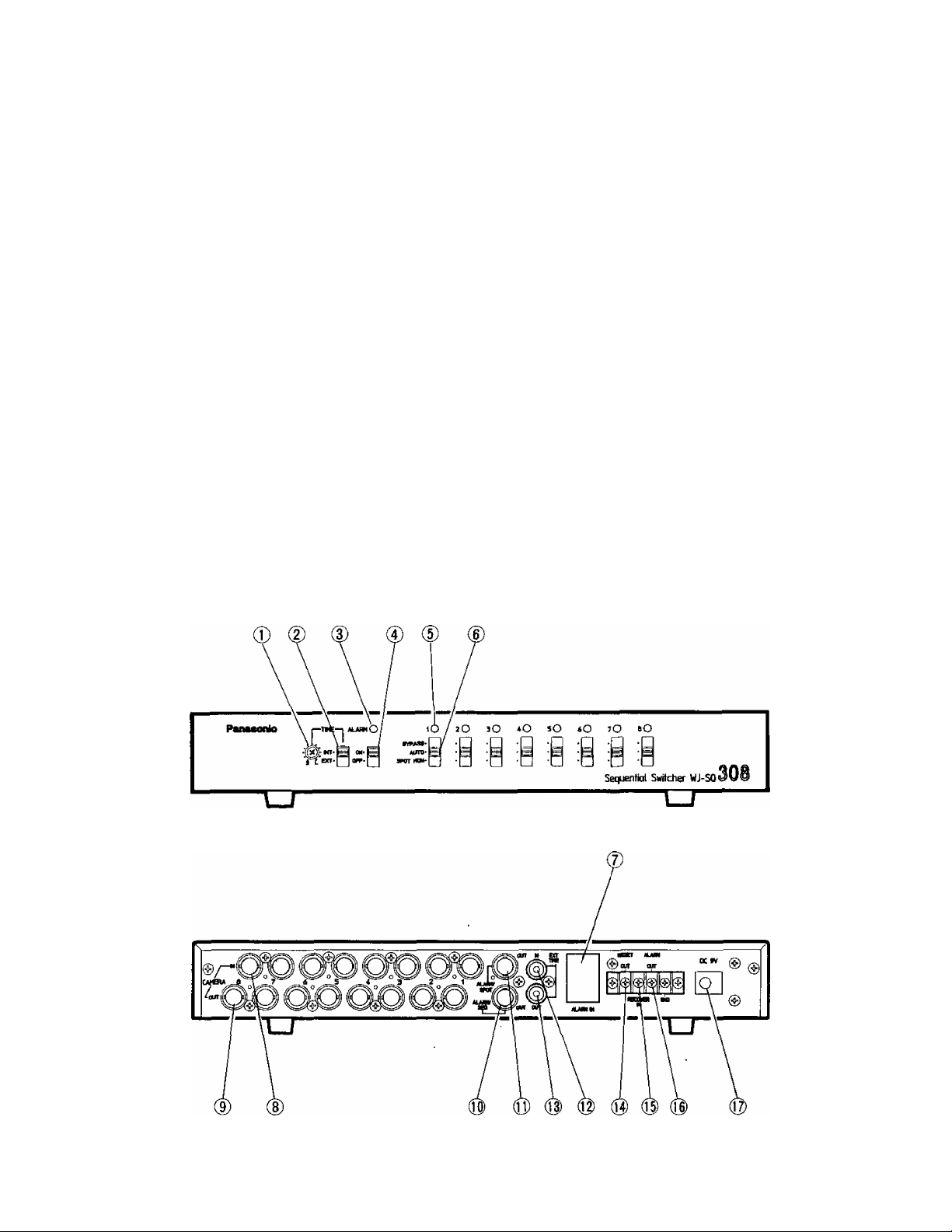
MAJOR OPERATING CONTROLS AND THEIR FUNCTIONS
-2-

1. Tíme Control (S/L)
The sequential switcher’s timing can be continuously
changed from approx, 1 to 30 seconds by turning this
control.
2. Time Internal / External Selection Switch (INT/EXT)
This switch is used to select the timing control signal
source.
INT: Select this position when the sequential
switcher’s timing is controlled using the Time
Controt(1).
EXT: Select this position when the sequential
switcher's timing is controlled by an external tim
ing pulse.
If trigger signals from a Time Lapse VTR are connect
ed to the External Timing Input Connector (12) when
using it in combination with this sequential switcher,
the sequential switcher will be controlled by the trigger
signals from that Time Lapse VTR.
3. Alarm Indicator
When the Alarm On/Off Selection Switch is set to the
ON position, this indicator lights.
When the alarm signal is supplied to the Alarm Signal
Input Connector in the Alarm On mode, this indicator
blinks.
4. Alarm On/Off Selection Switch (ON/OFF)
ON: Select this position when an alarm input into the
Alarm Input Connector will automatically operate
the alarm function. After a predetermining interval
of alarm operation, the norma! sequence opera
tion is resumed.
OFF: Select this position when the alarm function is
suspended so that no alarm operation will take
place even if an alarm input is received.
In this case, a reset signal will be output from the
Reset Output Terminal (14) of the Alarm Input
Connector (7) on the back panel.
5. Sequence Output Indicators (1/2/3/4/5/6/7/8)
A lit tamp indicates that the signals of the correspond
ing camera are available at the Camera Output
Connector.
6. 3-posltlon Selection Switches
(BYPASS/AUTO/SPOT MON)
a) b)
c)
a) BYPASS mode
When this switch is set to the BYPASS position,
the camera signals in this position will be skipped
regardless of the presence of a video signals
while the other camera signals will be fed out in
sequence. In other words, the signals of that cam
era will not be fed out of Alarm Sequential Output
Connector(IO). This function may be very.conve
nient in cases where monitoring requirements
vary from time to time.
b) AUTO mode
When the switch is set to this position, the signals
of the camera will be automatically in sequence
regardless of the presence of a video signal from
that source.
c) SPOT mode
When the switch is set to this position, the signals
of the camera in that position will be output from
of the Alarm Spot Output Connector(ll) so that
this camera signal can be selectively monitored.
During this time, sequence operation goes on and
sequence outputs are fed out from the Alarm
Sequential Output Connector(IO). If two or more
cameras are set in this mode, the signal of the
lower numbered camera in this position will be
used as output signal,
7. Alarm Input Connector (ALARM IN)
The alarm sensor closure switches are connected to
these terminals.
8. Camera Input Connectors (CAMERA IN)
These are used to connect the video output signals
from cameras. When connected, the signals will be
terminated at 75 ohms.
9. Camera Output Connectors (CAMERA OUT)
The video input signals connected to the Camera
Input Connectors (8) are looped through to these con
nectors.
10. Alarm Sequential Output Connector (ALARM/SEQ OUT)
This is a sequential switcher output connector which
always produces sequence outputs except during an
alarm connection when the output switches to the
alarmed camera position. .
BYPASS •
AUTO •
SPOT MON •
BYPASS •
AUTO •
SPOT MON •
N
BYPASS •
AUTO »
SPOT MON .
11. Alarm Spot Output Connector (ALARM/SPOT OUT)
This is a manual video switcher output connector,
s
-3-
which normally produces the same sequence opera
tion output signals as the alarm sequential output.
However, if a camera selection switch is in the SPOT
MON position, that camera will be output from this
connector.
 Loading...