

Page 1

Before attempting to connect or operate this product,
please read these instructions carefully and save this manual for future use.
Digital Disk Recorder
Operating Instructions
Model No. WJ-RT208
ERROR
ALARM
HDD
T
IM
E
R
1
2
3
4
5
6
7
8
9
0
M
E
N
U
E
S
C
A
L
A
R
M
R
E
S
E
T
S
E
Q
U
E
N
C
E
S
T
IL
L
C
O
P
Y
2
S
E
T
P
A
U
S
E
R
E
V
F
W
D
S
K
IP
S
T
O
P
P
L
A
Y
R
E
C
Digital Disk Recorder WJ-RT
O
P
E
R
AT
E
208
Page 2
WARNING:
• This apparatus must be earthed.
• Apparatus shall be connected to a mains socket outlet with a
protective earthing connection.
• The mains plug or an appliance coupler shall remain readily
operable.
• To prevent fire or electric shock hazard, do not expose this
apparatus to rain or moisture.
• The apparatus should not be exposed to dripping or splashing
and that no objects filled with liquids, such as vases, should be
placed on the apparatus.
• All work related to the installation of this product should be
made by qualified service personnel or system installers.
2
The serial number of this product may be found on the surface of the unit.
You should note the serial number of this unit in the space
provided and retain this book as a permanent record of your
purchase to aid identification in the event of theft.
Model No.
Serial No.
NOTE: This equipment has been tested and found to comply with the limits for a Class A digital device, pursuant to
Part 15 of the FCC Rules. These limits are designed to provide reasonable protection against harmful interference
when the equipment is operated in a commercial environment. This equipment generates, uses, and can radiate
radio frequency energy and, if not installed and used in
accordance with the instruction manual, may cause harmful
interference to radio communications.
Operation of this equipment in a residential area is likely to
cause harmful interference in which case the user will be
required to correct the interference at his own expense.
FCC Caution: To assure continued compliance, (example use only shielded interface cables when connecting to computer or peripheral devices). Any changes or modifications
not expressly approved by the party responsible for compliance could void the user’s authority to operate this equipment.
For U.S.A
The lightning flash with arrowhead symbol,
within an equilateral triangle, is intended to
alert the user to the presence of uninsulated
"dangerous voltage" within the product's
enclosure that may be of sufficient magnitude to constitute a risk of electric shock to
persons.
The exclamation point within an equilateral
triangle is intended to alert the user to the
presence of important operating and maintenance (servicing) instructions in the literature accompanying the appliance.
Power disconnection. Unit with or without
ON-OFF switches have power supplied to
the unit whenever the power cord is inserted
into the power source; however, the unit is
operational only when the ON-OFF switch is
in the ON position. The power cord is the
main power disconnect for all units.
CAUTION: TO REDUCE THE RISK OF ELECTRIC SHOCK,
DO NOT REMOVE COVER (OR BACK).
NO USER-SERVICEABLE PARTS INSIDE.
REFER SERVICING TO QUALIFIED SERVICE PERSONNEL.
CAUTION
RISK OF ELECTRIC SHOCK
DO NOT OPEN
SA 1965
SA 1966
This Class A digital apparatus complies with Canadian
ICES-003.
For Canada
Page 3

3
IMPORTANT SAFETY INSTRUCTIONS
1) Read these instructions.
2) Keep these instructions.
3) Heed all warnings.
4) Follow all instructions.
5) Do not use this apparatus near water.
6) Clean only with dry cloth.
7) Do not block any ventilation openings. Install in accordance with the manufacturer's instructions.
8) Do not install near any heat sources such as radiators, heat registers, stoves, or other apparatus (including amplifiers) that
produce heat.
9) Do not defeat the safety purpose of the polarized or grounding-type plug. A polarized plug has two blades with one wider
than the other. A grounding type plug has two blades and a third grounding prong. The wide blade or the third prong are
provided for your safety. If the provided plug does not fit into your outlet, consult an electrician for replacement of the
obsolete outlet.
10) Protect the power cord from being walked on or pinched particularly at plugs, convenience receptacles, and the point
where they exit from the apparatus.
11) Only use attachments/accessories specified by the manufacturer.
12) Use only with the cart, stand, tripod, bracket, or table specified by the manufacturer, or sold with the apparatus. When a
cart is used, use caution when moving the cart/apparatus combination to avoid injury from tip-over.
13) Unplug this apparatus during lightning storms or when unused for long periods of time.
14) Refer all servicing to qualified service personnel. Servicing is required when the apparatus has been damaged in any way,
such as power-supply cord or plug is damaged, liquid has been spilled or objects have fallen into the apparatus, the
apparatus has been exposed to rain or moisture, does not operate normally, or has been dropped.
S3125A
Page 4

4
Limitation of Liability
THIS PUBLICATION IS PROVIDED "AS IS" WITHOUT WARRANTY OF ANY KIND, EITHER EXPRESS OR IMPLIED,
INCLUDING BUT NOT LIMITED TO, THE IMPLIED WARRANTIES OF MERCHANTABILITY, FITNESS FOR ANY PARTICULAR PURPOSE, OR NON-INFRINGEMENT OF THE
THIRD PARTY'S RIGHT.
Disclaimer of Warranty
IN NO EVENT SHALL MATSUSHITA ELECTRIC INDUSTRIAL CO., LTD. BE LIABLE TO ANY PARTY OR ANY PERSON, EXCEPT FOR CERTAIN WARRANTY PROGRAM
OFFERED BY THE LOCAL DEALER OF PANASONIC, FOR
THE CASES INCLUDING BUT NOT LIMITED TO BELOW:
(1) ANY DAMAGE AND LOSS, INCLUDING WITHOUT LIM-
ITATION, DIRECT OR INDIRECT, SPECIAL, CONSEQUENTIAL OR EXEMPLARY, ARISING OUT OF OR
RELATING TO THE PRODUCT;
(2) PERSONAL INJURY OR ANY DAMAGE CAUSED BY
INAPPROPRIATE USE OR NEGLIGENT OPERATION
OF THE USER;
(3) UNAUTHORIZED DISASSEMBLY, REPAIR OR MODIFI-
CATION OF THE PRODUCT BY THE USER;
(4) INCONVENIENCE OR ANY LOSS ARISING WHEN
IMAGES ARE NOT DISPLAYED, DUE TO ANY REASON
OR CAUSE INCLUDING ANY FAILURE OR PROBLEM
OF THE PRODUCT;
(5) ANY PROBLEM, CONSEQUENTIAL INCONVENIENCE,
OR LOSS OR DAMAGE, ARISING OUT OF THE SYSTEM COMBINED BY THE DEVICES OF THIRD PARTY.
THIS PUBLICATION COULD INCLUDE TECHNICAL INACCURACIES OR TYPOGRAPHICAL ERRORS. CHANGES
ARE ADDED TO THE INFORMATION HEREIN, AT ANY
TIME, FOR THE IMPROVEMENTS OF THIS PUBLICATION
AND/OR THE CORRESPONDING PRODUCT (S).
Page 5

5
Precautions
• Refer all work related to the installation of this appliance
to qualified service personnel or system installers.
• Prevent condensation from forming on the surface of
the hard disk. Wait until the moisture evaporates in any
of the following cases:
The recorder is moved to a place significantly different
in temperature or humidity.
The recorder is moved outside of an air-conditioned
room.
The recorder is placed in an extremely humid place.
The recorder is placed in a room where a heater has
just been turned on.
• Consumable parts
Contact your dealer for replacement of the following
parts when the time comes:
Built-in hard disk needs replacement after around
30 000 hours of operation.
Cooling fan also needs replacement after around
30 000 hours of operation.
Backup battery has a lifetime of around five (5) years in
an ordinary environment.
• Do not block the ventilation opening or slots on the
cover.
To prevent the appliance from overheating, place it at
least 5 cm (2 inches) away from the wall.
Trademarks and Registered Trademarks
About These Operating Instructions
• Microsoft, Windows, Direct X, and Windows XP are registered trademarks of Microsoft Corporation in the U.S.
and/or other countries.
• Adobe, Adobe logos, and Acrobat are registered trademarks of Adobe Systems Incorporated in the U.S. and/
or other countries.
The WJ-RT208 comes with the following instruction manuals:
Operating Instructions (This Document)
The Operating Instructions explain how to operate the unit
with the buttons on the front panel.
• Other names of companies and products contained in
these operating instructions may be trademarks or registered trademarks of their respective owners.
Network Operating Instructions (PDF)
Refer to the Network Operating Instructions (PDF) for
descriptions of how to operate this unit using a PC.
Adobe
®
Reader is required to read the Network Operating
Instructions (PDF). When the Adobe
®
Reader is not
installed on the PC, download the latest Adobe
®
Reader
from the Adobe web site and install it.
• Do not drop metallic parts through slots.
This could permanently damage the appliance. Turn
the power off and refer servicing to qualified service
personnel.
• Handle the appliance with care. Do not strike or shake,
as this may damage the appliance.
• We recommend that you note down your settings and
keep the notes. Power or battery failure may erase settings you entered.
• Do not expose the appliance to water or moisture, nor
try to operate it in wet areas.
• Do not use strong or abrasive detergents when cleaning the appliance body.
Use a dry cloth to clean the appliance when it is dirty.
When the dirt is hard to remove, use a mild detergent
and wipe gently.
• Do not operate the appliance beyond its specified temperature, humidity, or power source ratings.
Do not use the appliance in an extreme environment
where there are high temperatures or high humidity.
Use the appliance at temperatures within +5 °C to
+45 °C (41 °F to 113 °F) and humidity +5 - 90 % (without
condensation).
The input power source for this appliance is 120 V AC,
60 Hz.
•A malfunction of RECORD or PLAY, or damage or
defect of recorded data, can occur due to machine failure or problems. Any consequent damage or loss arising from such problems is not subject to the warranty.
Page 6

6
CONTENTS
Important Safety Instructions ...................................................................................................................... 3
Limitation of Liability ................................................................................................................................... 4
Disclaimer of Warranty ............................................................................................................................... 4
Precautions ................................................................................................................................................. 5
Trademarks and Registered Trademarks ................................................................................................... 5
About These Operating Instructions ........................................................................................................... 5
Preface ....................................................................................................................................................... 7
Features ..................................................................................................................................................... 7
Major Operating Controls & Their Functions .............................................................................................. 8
■ Front View ............................................................................................................................................ 8
■ Rear View ............................................................................................................................................ 10
Installation .................................................................................................................................................. 11
■ Installing the Hard Disk ........................................................................................................................ 11
System Composition and Connections ....................................................................................................... 14
<Basic System> ........................................................................................................................................ 14
<Network System> ................................................................................................................................... 16
Setup Procedures ....................................................................................................................................... 22
1. Preparation ........................................................................................................................................... 22
2. Operation .............................................................................................................................................. 26
3. Setup .................................................................................................................................................... 32
System Screen Explanations ...................................................................................................................... 49
Setup Menu Parameters and Initial Setup Values ...................................................................................... 50
Operation using the system controller ........................................................................................................ 56
Troubleshooting .......................................................................................................................................... 58
Specifications ............................................................................................................................................. 59
■ Basic Specifications ............................................................................................................................. 59
■ Table of Recording Length .................................................................................................................. 60
Standard Accessories ................................................................................................................................. 60
Page 7

7
Preface
Features
The Digital Disk Recorder WJ-RT208 is a professional security product with eight video and audio inputs. It is capable of
recording high-quality video/audio data over an extended period of time. In addition to image recording and playback, the
many features of the WJ-RT208 include motion detection, external alarm recording, remote operation via a network, and network communication. An RS485 interface is provided for connection with peripheral devices.
The recorder can be controlled by the system controller WV-CU650.
Disk configuration: Up to 8 hard disks can be installed
2 hard disks factory-installed (WJ-RT208)
Live monitoring: Single channel live monitoring (CH 1-8)
1-, 4-, 6-, 9-split screen
Camera control
Recording mode: Manual recording
Timer recording
Power-on auto recording
Terminal recording
Motion detection (VMD) recording
Recording quality, frame rate, stream type setup
Compression methods: Video: MPEG-4
Audio: ADPCM
Playback mode: Single channel playback
Time & date search playback
Network remote playback
Remote download and local playback
Playback after backup
Network monitoring: Live monitoring
Remote playback
Camera control
Live network communication
Others: Password key protection
Running log record
Original heat radiation design
Operable using the connected system controller
Page 8
8
Major Operating Controls & Their Functions
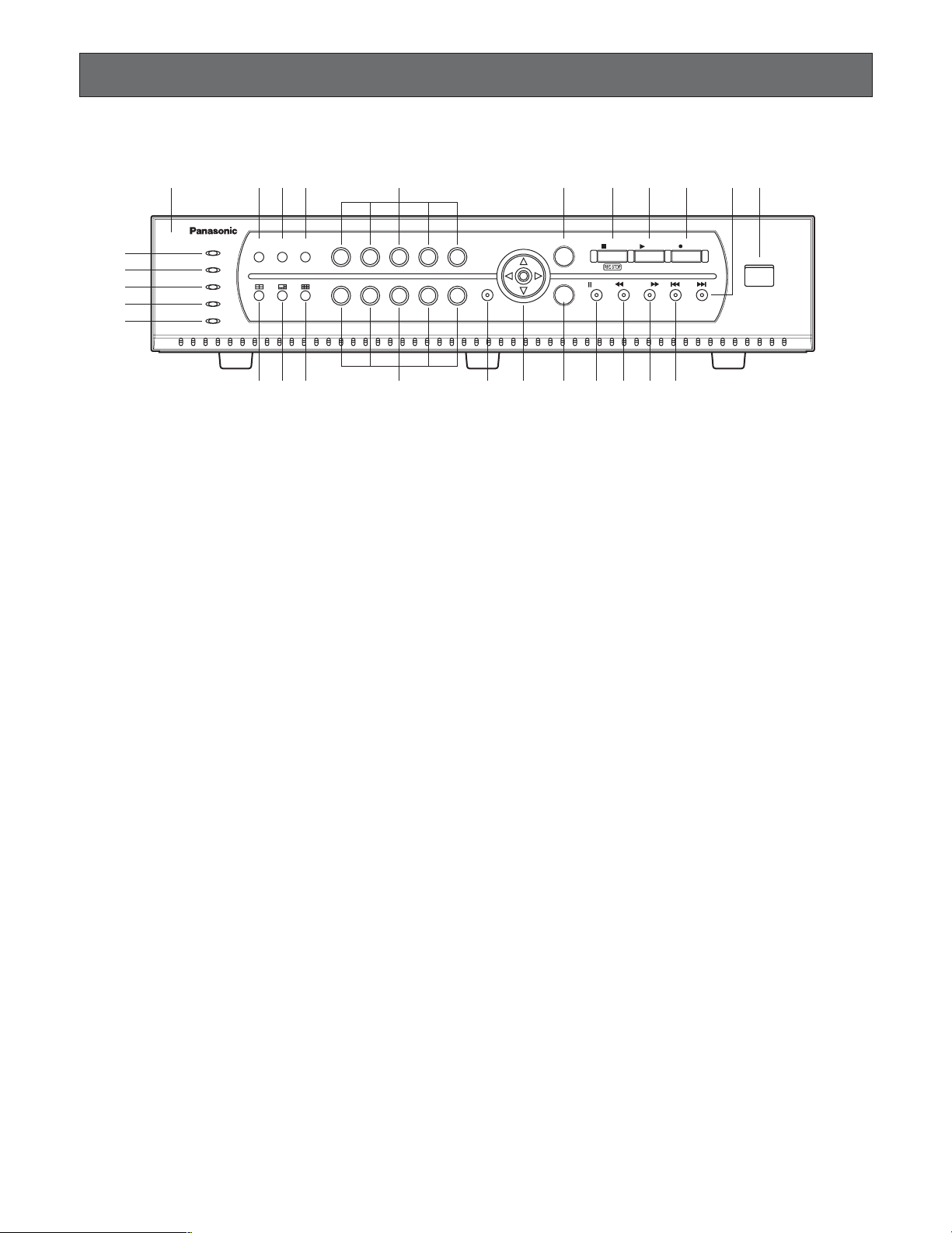
■ Front View
208
qu
!
!1!
!
i
!4!5!7@1@2@3@
o !
!
!8!9@
@
q Front Panel
w Error Indicator (ERROR)
Lights Red: HDD error, HDD removed automatically.
Lights Orange: Internal thermal error or fan stop error
e Alarm Indicator (ALARM)
Blinks when alarm is activated. It changes to a steady
light when the activated alarm is reset after the autoreset time has elapsed.
To turn the indicator off, press the [ALARM RESET] button.
r HDD Access Indicator (HDD)
Lights up when the HDD is accessed.
t Timer Recording Indicator (TIMER)
Lights when timer recording is set. Blinks when recording starts.
y Operate Indicator (OPERATE)
Lights up when the power of the WJ-RT208 Digital Disk
Recorder is on.
u Alarm Reset Button (ALARM RESET)
Pressing this button cancels an activated alarm.
i Still Button (STILL)
Pressing this button switches the currently displayed
picture to a still picture.
o Sequence Button (SEQUENCE)
Runs the assigned sequence on the monitor screen for
the specified duration. Pressing this button starts/stops
the sequence.
!0 4-split Screen Button
Pressing this button splits the screen into four segments
displaying the surveillance pictures on Channels 1 to 4.
Pressing the button again displays the next four surveillance pictures on Channels 5 to 8.
!1 6-split Screen Button
Pressing this button splits the screen into six segments
displaying the surveillance pictures on Channels 1 to 6.
Refer to page 26 for further information. The camera
selection button is disabled in this mode.
!2 9-split Screen Button
Pressing this button splits the screen into nine segments displaying the surveillance pictures on Channels
1 to 8.
!3 Camera Selection Buttons (Numeric Button)
Pressing a button selects the input live image, or the
recorded image of the specified input.
While a channel is recording, the corresponding button
lights up in orange.
These buttons are used for password input to release
the button lock function.
!4 Menu Button (MENU)
Pressing this button opens the main menu.
!5 Direction Button
↑: Up button
• Menu:
The cursor moves upwards on the menu or dialog.
•Camera control:
Controls the upward movement of the camera.
Images will be zoomed in.
HDD
TIMER
ALARM
RESET
w
e
r
t
y
ERROR
ALARM
OPERATE
0
SEQUENCESTILL
1 2 3 4 5
6 7 8 90
2
3
MENU
3
6
ESC
SET
STOP PLAY REC
PAUS E REV FWD SKI P
0
COPY 2
Digital Disk Recorder WJ-RT
4
6@5
208
Page 9

9
↓: Down button
• Menu:
The cursor moves downwards on the menu or dialog.
•Camera control:
Controls the downward movement of the camera.
Images will be zoomed out.
←: Left button
• Menu:
Moves the cursor to the left or changes option
parameters.
•Camera control:
Controls the movement of the camera to the left.
Shifts the focus nearer.
Closes the iris.
→: Right button
• Menu:
Moves the cursor to the right or changes option
parameters.
•Camera control:
Controls the movement of the camera to the right.
Shifts the focus farther.
Opens the iris.
!6 Cancel Button (ESC)
To return to the previous menu, press this button.
When the menu is not displayed, pressing this button
once activates the mute function. To release the mute
function, press this button again.
!7 Set Button (SET)
In a dialog box, this button is used to OK a selected
parameter.
When controlling the camera, this button is used to
change the control mode (pan/tilt
→ zoom/focus → iris).
When setting the motion detection area, it is used to
change the points describing the detection area.
!8 Stop Button (STOP)
Pressing this button for two seconds stops recording.
In playback mode, pressing this button stops playback.
!9 Play Button (PLAY)
Pressing this button plays back the images recorded on
the current channel.
When this button is pressed in pause mode, the next
frame will be displayed.
When this button is pressed while panning/tilting operation, the auto function of the camera will be activated.
@0 Recording Button (REC)
Pressing this button starts recording the data on the
current channel. If the camera control is ON, the current
position of the camera is saved as preset position.
@1 Pause Button (PAUSE)
Pauses playback.
@2 Fast Reverse Play Button (REV)
Starts fast reverse playback. Three playback speeds
are available.
@3 Fast Forward Play Button (FWD)
Starts fast forward playback. Three playback speeds
are available.
@4@5 Skip Playback Button (SKIP)
Skips to the previous or next recorded data, and plays
the data from its beginning.
@6 Copy Connector (COPY 2)
This connector is for connecting an external hard disk
to back up the data recorded on the hard disks.
Page 10
10
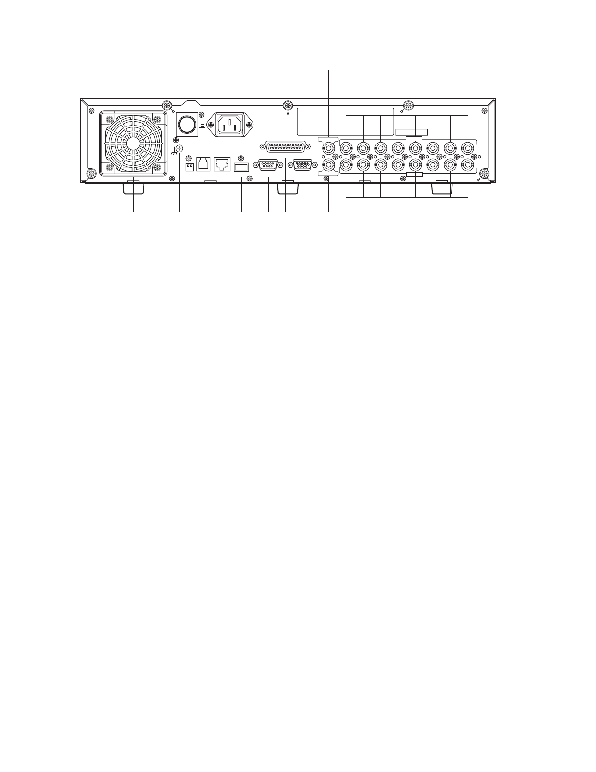
■ Rear View
q Power Cooling Fan
Prevents the temperature of the recorder from rising. Do
not block the ventilation openings.
w AC Power Connector (AC IN)
Connect the supplied power cable to this AC power
connector.
e Power Switch (POWER)
This switch turns the power of the disk recorder on and
off.
r Signal Ground Terminal (SIGNAL GND)
t Mode Selection DIP switches (MODE)
This 2-bit DIP switch is used for setting the terminal system. Refer to DIP Switch Setting for details.
y Data Port (DATA)
This port is for data communication with external
devices.
u 10Base-T/100Base-Tx Port (10/100BASE-T)
This port is used to exchange control data with Ethernet
via an Ethernet Hub.
i Copy Port (COPY1)
This port is used to connect an external hard disk to
back up the data recorded on the hard disks.
o Serial Data Port (SERIAL)
For servicing purpose only.
!0 Terminal/Control Port (TERMINAL/CONTROL)
This port controls terminal inputs 1-8 and alarm outputs
1-3. It is also used to connect component cameras with
the RS485 protocol feature.
!1 VGA Output Port (MONITOR (VGA))
When a VGA monitor is connected to this port, the
same image as supplied from the video output terminal
is obtained.
!2 Video Output Connector (VIDEO OUT)
Spot live, split-screen, and playback pictures are output
from this BNC connector. All menu settings and screen
display information are also output from this connector.
!3 Video Input Connectors (VIDEO IN 1-8)
System cameras or component cameras are connected
to these BNC connectors. A 75 Ω termination is made
unless the video output terminal is connected.
!4 Audio Input Connectors (AUDIO IN 1-8)
These are used for BNC standard jacks. Each of them
accept an unbalanced –10 dBV, 22 kΩ line input audio
signal supplied from an external device.
!5 Audio Output Connector (AUDIO OUT)
This is used for a BNC standard jack that supplies an
unbalanced –10 dBV, 22 Ω line output audio signal to
an external device.
!
!
e w
ON
OFF
POWER
SIGNAL GND
MODE
DATA
AC IN
10/100BASE-T
COPY1
TERMINAL/CONTROL
SERIAL
MONITOR(VGA)
5
AUDIO OUT
VIDEO OUT
112233445566778
4
AUDIO IN
VIDEO IN
8
!3!2!1!0oiuytq r
Page 11
11
Installation
This installation should be made by qualified service personnel or system installers.
● Cautions
Places to avoid
• Direct exposure to sunlight or near a source of heat such as a radiator.
• Very dirty and dusty places. Places subject to strong vibrations.
• Near a transformer, dimmer, video player, radio, or monitor. These may cause humming noises, etc.
About mounting
• Do not block the ventilation openings or slots in the cover to prevent the appliance from overheating.
• Always keep the temperature in the rack within +45 °C (113 °F).
• Secure the rear of the appliance to the rack with additional mounting brackets (procured locally), if the rack is subject to
vibration.
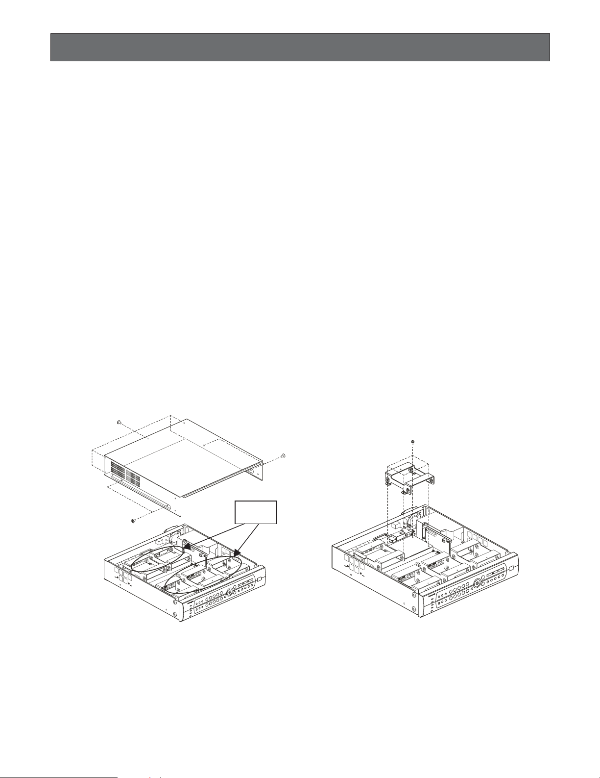
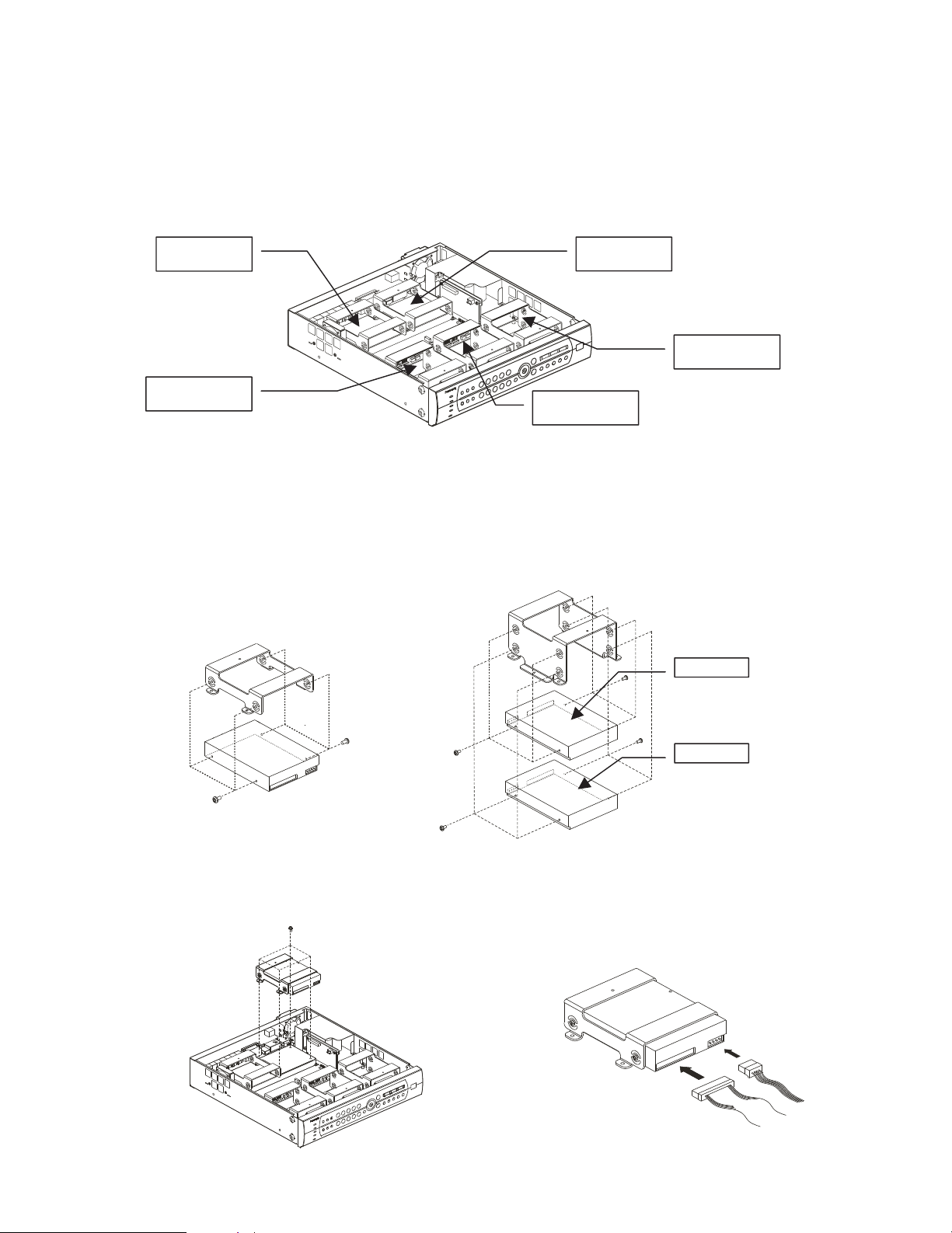
■ Installing the Hard Disk
There is space for up to 8 hard disks.
The unit is provided with four IDE interfaces, allowing installation of up to eight hard disks.
1. Turning off the power.
Please check the rear of the unit and confirm that the power switch is turned off, the power cord has been disconnected,
and the [OPERATE] indicator is off.
2. Remove the top cover.
Remove four screws on the side panel and five screws at the rear to remove the top cover (see Fig. 1).
3. Remove the hard disk fixing frame.
Of the five hard disk fixing frames, the three frames nearest the front panel can accept two hard disks each. The two
frames near the rear panel will accept one hard disk each.
If you need to remove a hard disk fixing frame, be careful not to damage the fan connection terminal and the hard disk
cable. (Fig. 2)
HDD fixing
frames
Fig. 2Fig. 1
Page 12
12
4. Ready the hard disk and install wire jumpers.
To connect two hard disks to one IDE interface, make sure to designate one as the Master HDD and the other the Slave
HDD. If only one hard disk is connected, make this the Master HDD. (For connection of the Master and Slave HDD, refer to
the operating instructions of the hard disk.)
Pay attention to the following when choosing the connection position of the Master and Slave HDD.
(1) When connecting two hard disks to IDE port 1, make the one on the left the Master and the one on the right the Slave,
as seen from the front of the recorder. See Fig. 3.
(2) When connecting three pairs of hard disks to IDE port 0, 2 and 3 (6 in total), make the top one the Master and the bot-
tom one the Slave (see Figs. 3 and 5).
Note: Port 0 was installed to the two disks installed model. Port 0 and 1 were installed to the four disks installed model.
(For the relation between hard disk positions refer to the figure above or the explanation on hard disk management on
page 47.)
5. Insert the hard disk into the hard disk fixing frame.
Fix it with four screws at the side of the frame. (Fig. 4, 5)
6. Insert the hard disk fixing frame in the proper location inside the recorder and fix it with a screw (Fig. 6). (Be careful not to
damage the fan connection terminal and hard disk cable.)
Master HDD of
IDE port 1
HDD connected
to IDE port 0
Slave HDD of
IDE port 1
HDD connected
to IDE port 3
HDD connected
to IDE port 2
Fig. 3
Master HDD
Slave HDD
Fig. 4
Fig. 5
Fig. 6 Fig. 7
Page 13

13
7. Connect the flat hard disk data cable and power cord (Fig. 7).
Seen from the front of the recorder, the IDE interface is numbered 0, 1, 2, 3 from left to right. Connect the four power supply ports and four IDE data ports on the motherboard with the correspondingly numbered hard disk connectors.
(For the relation between hard disk positions refer to the figure above or the explanation on hard disk management on
page 47.)
8. Follow the same procedure to install other hard disks.
Note: Up to eight hard disks can be installed.
9. Replace the top cover. (Refer to Fig. 1)
10. For formatting hard disks refer to page 47 of these Operating Instructions.
Page 14
The WJ-RT208 is used to connect cameras, microphones, monitors, VGA monitors, PCs, networks, cameras, external HDDs,
and more. (According to the interface type, some devices cannot be connected.)
In regard to two types of system configurations and connections, a brief explanation is given below. In regard to more complicated system connections as well as the system connections not introduced in this Operating Instructions, refer all work related to the connection of this product to qualified service personnel or system installers.
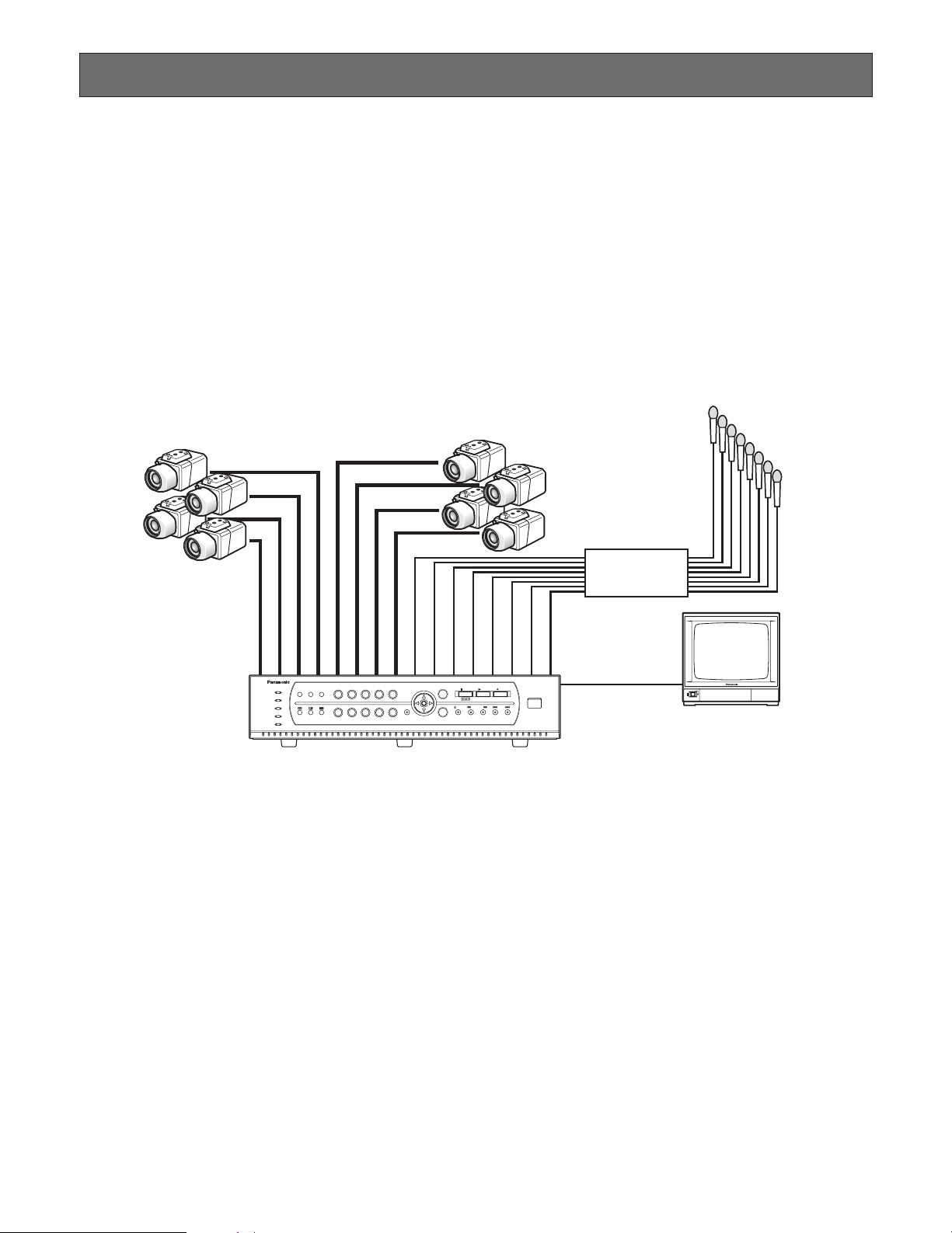
<Basic System>
■ Example for Basic System Connections
● Basic Connection
Cautions:
q Camera cable length (BNC) is a maximum of 500 m.
w The audio signals from a microphone are firstly amplified at the amplifier and then fed to the WJ-RT208.
14
System Composition and Connections
208
Camera Camera
Amplifier
ALARM
ERROR
SEQUENCESTILL
RESET
ALARM
HDD
TIMER
OPERATE
1 2 3 4 5
6 7 8 90
MENU
ESC
PAUSE REV FWD SKIP
SET
STOP PLAY REC
Digital Disk Recorder WJ-RT
COPY 2
208
Microphones
Page 15
15
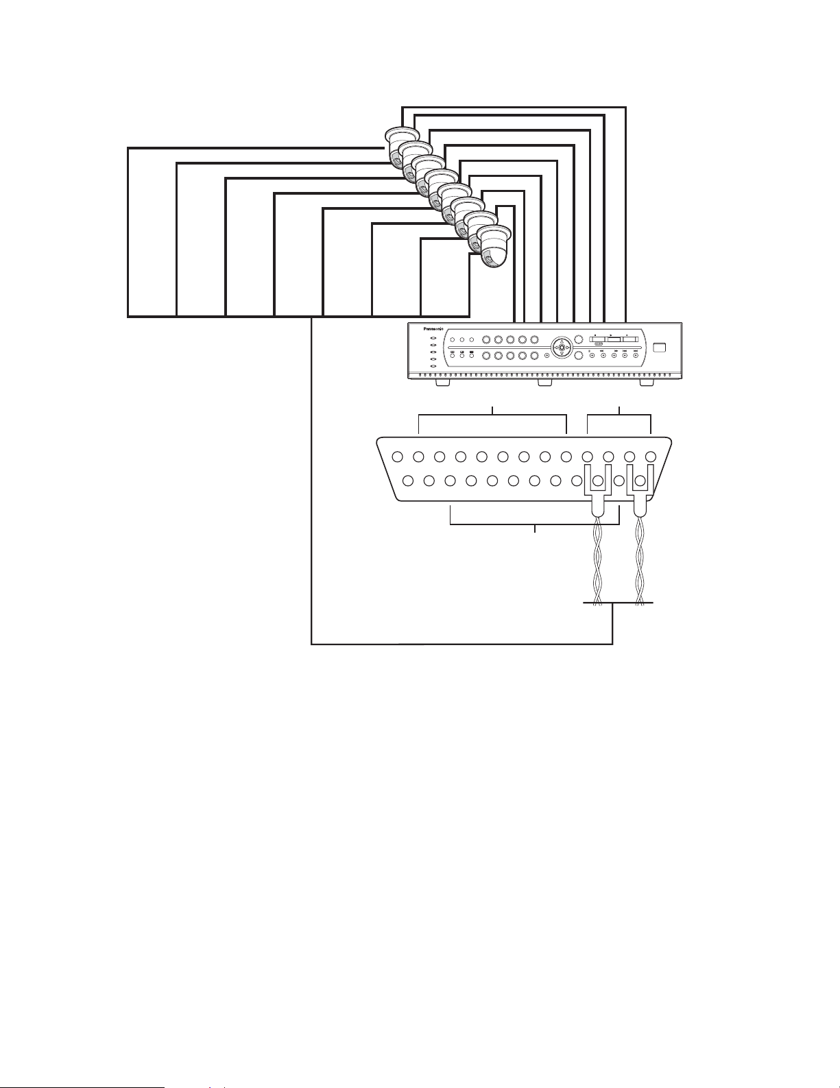
● Connection with RS485 Camera
Cautions:
q Camera cable length (RS485) is a maximum of 1 200 m.
w Only the 4-pin RS485 signal cable can be used.
208
RS485 Camera
WJ-RT208
TERMINAL/CONTROL interface
ALARM
ERROR
SEQUENCESTILL
RESET
ALARM
HDD
TIMER
OPERATE
1 2 3 4 5
6 7 8 90
MENU
ESC
PAUSE REV FWD SKIP
SET
STOP PLAY REC
TERMINAL IN RS485
+12V
GND8GND7COM36NC35NO34COM23NC22NO21COM1RBNC1RANO1TBGND
ALARM OUT
Digital Disk Recorder WJ-RT
TA
COPY 2
208
Page 16
16
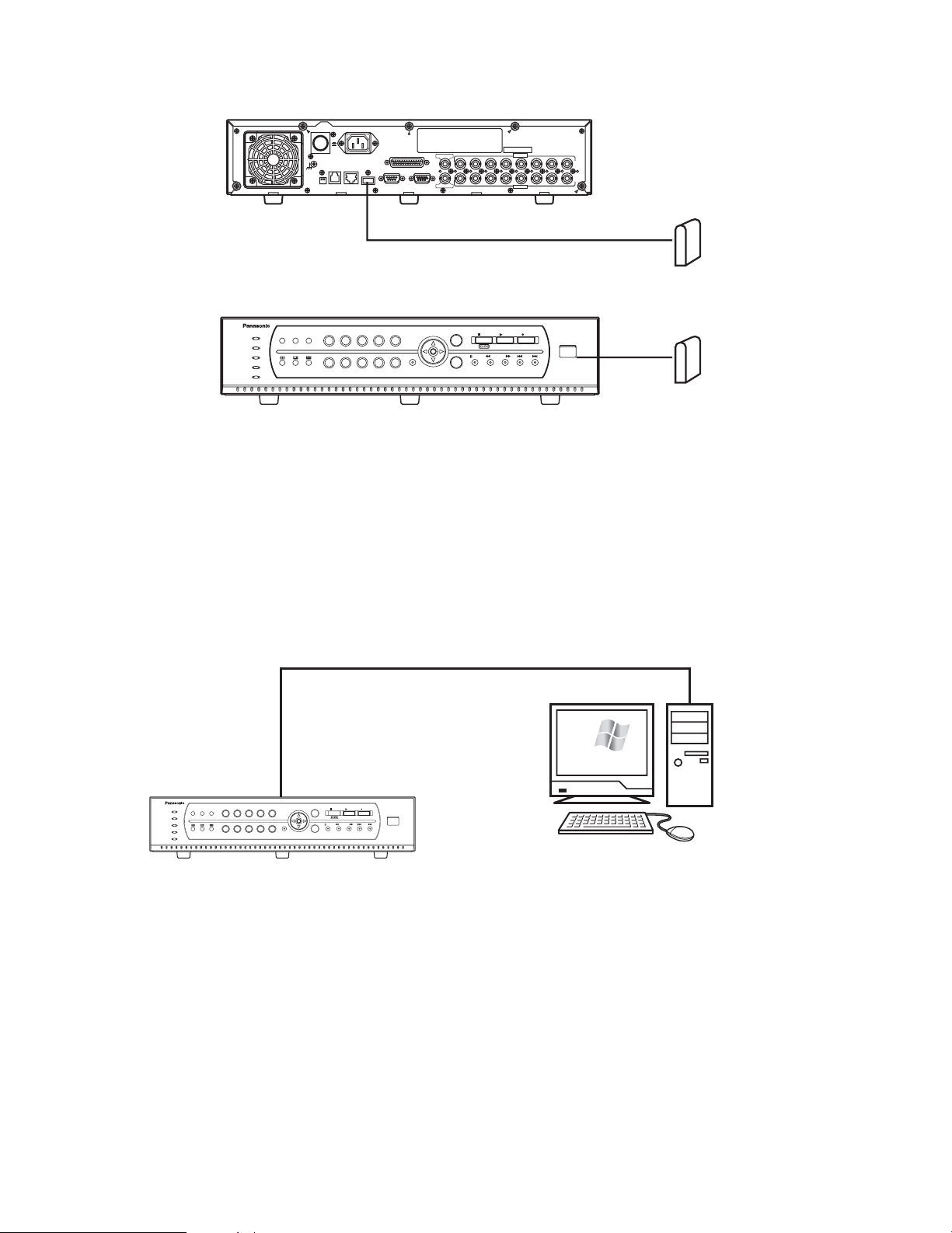
● Connection with External HDD (For Data Backup)
<Network System>
■ Example for Network System Connection
● Direct PC Connection
208
208
ON
OFF
POWER
AC IN
SIGNAL GND
MODE
DATA
10/100BASE-T
COPY1
TERMINAL/CONTROL
SERIAL
To COPY1 port USB cable (Locally procured)
MONITOR(VGA)
AUDIO OUT
112233445566778
VIDEO OUT
AUDIO IN
VIDEO IN
8
External HDD
ALARM
ERROR
ALARM
OPERATE
HDD
TIMER
SEQUENCESTILL
RESET
1 2 3 4 5
6 7 8 90
ESC
MENU
PAUS E REV FWD SKIP
SET
LAN cable (Not provided: 10Base-T/100Base-Tx, Category 5, Cross)
STOP PLAY REC
COPY 2
Digital Disk Recorder WJ-RT
208
Microsoft
Windows
External HDD
xp
ALARM
ERROR
SEQUENCESTILL
RESET
ALARM
HDD
TIMER
OPERATE
1 2 3 4 5
6 7 8 90
MENU
IP Address: 192.168.0.88
Subnet Mask: 255.255.255.0
ESC
PAUSE REV FWD SKIP
SET
STOP PLAY REC
Digital Disk Recorder WJ-RT
COPY 2
208
PC/AT Compatible
IP Address: 192.168.0.x (except 0, 88 and 255)
Subnet Mask: 255.255.255.0
Page 17

17
● Connections with any Existing Network System
● Connections with a Broadband WAN Network
Caution: The number of clients that can be connected to each WJ-RT208 is defined in the next table. According to differences
in the network communication protocol, the number of clients that can be connected can differ. In the next table, the number of clients that can be connected is defined for the TCP/UDP protocol and the MCAST protocol, independently of each
other.
208
WAN
Windows
xp
Microsoft
PC/AT Compatible
Server Port: 2000 (changeable)
Alarm Port: 4000 (changeable)
Forward (WAN → DVR)
UDP Port: 9998 (fixed)
TCP Port: 2000 (depends on the
recorder settings)
Broadband router A
Forward (WAN → PC)
UDP Port: 999 (fixed)
TCP Port: 4000 (depends on the
recorder settings)
Broadband router B
ERROR
ALARM
HDD
TIMER
OPERATE
1 2 3 4 5
6 7 8 9 0
MENU
ESC
ALARM
RESET
SEQUENCESTILL
PAUSE REV FWD SKIP
STOP PLAY REC
COPY 2
SET
Digital Disk Recorder WJ-RT
208208
Notes:
1. Broadband router A can only connect one WJ-RT208. (Each WJ-RT208 should
be assigned a Global IP address.)
2. Broadband router B can only connect one PC/AT compatible machine.
(Each compatible machine should be assigned a global IP address.)
User type TCP/UDP MCAST
Manager 1 person 1 person
8 persons Unlimited in the same subnet
1 person 1 person
4 persons Frame play not available
1 person 1 person
Remote monitoring
Remote playback/net backup
Frame play
Remote talk
ALARM
ERROR
SEQUENCESTILL
RESET
ALARM
HDD
TIMER
OPERATE
1 2 3 4 5
6 7 8 90
MENU
IP Address: 192.168.0.88
Subnet Mask: 255.255.255.0
Gateway Address: 192.168.0.1
ESC
PAUSE REV FWD SKIP
SET
STOP PLAY REC
COPY 2
Digital Disk Recorder WJ-RT
208
LAN cable
(Not provided: 10BASE-T/100BASE-Tx, Category 5, Straight)
HUB/Router
Microsoft
Windows
xp
PC/AT Compatible
IP Address: 192.168.0.x (x except 0, 1, 88, 255)
Subnet Mask: 255.255.255.0
Gateway Address: 192.168.0.1
IP Address: 192.168.0.1
Subnet Mask: 255.255.255.0
LAN
Microsoft
Windows
PC/AT Compatible
xp
Page 18

• Connection with PS·Data systems
This is an example of connection when the unit is used together with the PS·Data devices.
If a connected system controller is PS·Data compatible, it is possible to operate this unit or connected devices using the system controller.
Use the RS485 cable provided with the system controller.
Important:
• Terminate both devices on both ends of the connection. Refer to the respective operating instructions for the descriptions
of how to terminate. Termination of this unit can be set with the DIP termination switch on the rear panel. (See page 21.)
• When connecting a PS·Data compatible device, it is necessary to set each item of "DATA PORT SETUP" of "COMMUNICATION SETUP" on the "WJ-RT208 SETUP MENU" according to the system configuration.
• The following are available PS·Data compatible devices.
• System controller: WV-CU650
• Matrix switcher: WJ-SX150
• Data multiplex unit: WJ-MP204
(Any other PS·Data compatible devices are not to be connected.)
When connecting a single unit with a controller
MODE
DATA
10/100BASE-T
COPY1
SERIAL
MONITOR(VGA)
TERMINAL/CONTROL
AUDIO OUT
VIDEO OUT
AC IN
SIGNAL GND
POWER
112233445566778
8
ON
OFF
VIDEO IN
AUDIO IN
This unit
1ON2
Mode switch
A B
1
3
2
4
6
5
7
9
8
0
SYSTEM CONTROLLER
Controller
Termination: ON
Unit address: 1
RS485 cable
(provided with the controller)
When connecting multiple units with a controller
"WJ-RT208 SETUP MENU" → "COMMUNICATION SETUP" → "DATA PORT SETUP" → "Unit
Address (System)": 1
18
RS485 cable
(provided with the controller)
SYSTEM CONTROLLER
Controller
Termination: ON
Unit address: 1
A B
1
2
3
4
5
6
7
8
9
0
1st unit (this unit)
RS485 cable
Unit address
(system): 1
2nd unit (this unit)
Unit address
(system): 2
RS485 cable
RS485 cable
Mode switch
1ON2
ON
POWER
SIGNAL GND
MODE
OFF
AC IN
DATA
10/100BASE-T
COPY1
TERMINAL/CONTROL
SERIAL
MONITOR(VGA)
AUDIO OUT
VIDEO OUT
AUDIO IN
112233445566778
VIDEO IN
8
Mode switch
1ON2
ON
POWER
SIGNAL GND
MODE
OFF
AC IN
DATA
10/100BASE-T
COPY1
TERMINAL/CONTROL
SERIAL
MONITOR(VGA)
AUDIO OUT
VIDEO OUT
AUDIO IN
112233445566778
VIDEO IN
8
3rd unit (this unit)
Unit address
(system): 3
RS485 cable
ON
OFF
POWER
SIGNAL GND
MODE
DATA
10/100BASE-T
AC IN
TERMINAL/CONTROL
SERIAL
COPY1
AUDIO OUT
MONITOR(VGA)
VIDEO OUT
Mode switch
1ON2
AUDIO IN
112233445566778
VIDEO IN
8
Page 19

19
When controlling cameras with coaxial and PS·Data communication systems
■ When using WJ-SX150
MODE
DATA
10/100BASE-T
COPY1
SERIAL
MONITOR(VGA)
TERMINAL/CONTROL
AUDIO OUT
VIDEO OUT
AC IN
SIGNAL GND
POWER
112233445566778
8
ON
OFF
VIDEO IN
AUDIO IN
MODE
DATA
10/100BASE-T
COPY1
SERIAL
MONITOR(VGA)
TERMINAL/CONTROL
AUDIO OUT
VIDEO OUT
AC IN
SIGNAL GND
POWER
112233445566778
8
ON
OFF
VIDEO IN
AUDIO IN
A B
1
3
2
4
6
5
7
9
8
0
SYSTEM CONTROLLER
1ON2
1ON2
Controller
Termination: ON
Unit address: 1
Matrix switcher
Termination: ON
Unit address: 1 - 4
RS485 cable
(provided with the controller)
Combination
camera
System camera
BNC cable
(option)
BNC cable (option)
First unit (this unit)
Unit address (system): 5
Second unit
Unit address (system): 6
RS485 cable
RS485 cable
RS485 cableRS485 cable
Mode switch
Mode switch
■ When using WJ-MP204
MODE
DATA
10/100BASE-T
COPY1
SERIAL
MONITOR(VGA)
TERMINAL/CONTROL
AUDIO OUT
VIDEO OUT
AC IN
SIGNAL GND
POWER
112233445566778
8
ON
OFF
VIDEO IN
AUDIO IN
MODE
DATA
10/100BASE-T
COPY1
SERIAL
MONITOR(VGA)
TERMINAL/CONTROL
AUDIO OUT
VIDEO OUT
AC IN
SIGNAL GND
POWER
112233445566778
8
ON
OFF
VIDEO IN
AUDIO IN
A B
1
3
2
4
6
5
7
9
8
0
SYSTEM CONTROLLER
1ON2
1ON2
Controller
Termination: ON
Unit address: 1
Data multiplex unit
Termination: ON
Unit address: 3
RS485 cable
(provided with the controller)
Combination
cameras
BNC cable
(option)
BNC cable (option)
First unit (this unit)
Unit address (system): 1
Second unit
Unit address (system): 2
RS485 cable
RS485 cableRS485 cable
Mode switch
Mode switch
RS485 cable
Page 20

The requirements of the alarm
signal level are as follows:
Low level: 0 V to 0.8 V
High level: more than 3.3 V
(max. 12 V)
Pulse width: 2 s or more
3 s or less
q Relay output: max. 30 VDC,
1 A or 125 VAC, 0.3 A
2
3
4
5
6
7
8
9
10
11
12
13
14
15
16
17
18
19
20
21
22
23
24
25
1
20
■ RS485 Connection
A 25-pin connector is used to accept and supply control signals.
TERMINAL/CONTROL
Internal block diagram
13
25
1
14
RA
TA
RB
TB
Pin No. Signal Operation Remarks
TA
TB
RA
RB
Terminal input 1
Terminal input 2
Terminal input 3
Terminal input 4
Terminal input 5
Terminal input 6
Terminal input 7
Terminal input 8
+12 V
Grounding
Alarm Output 1 (N.O.)
Alarm Output 1 (N.C.)
Alarm Output 1 (Common)
Alarm Output 2 (N.O.)
Alarm Output 2 (N.C.)
Alarm Output 2 (Common)
Alarm Output 3 (N.O.)
Alarm Output 3 (N.C.)
Alarm Output 3 (Common)
Grounding
Grounding
Sends the alarm signal to external
alarm unit 2.
Sends the alarm signal to external
alarm unit 3.
+12 V voltage output
Sends the alarm signal to external
alarm unit 1.
RS485 camera sending + data
RS485 camera sending – data
RS485 camera receiving + data
RS485 camera receiving – data
When an alarm occurs in channels 1
– 8, the alarm signals are sent to the
recorder through these ports.
Page 21

21
■ DIP Switch Setting
When this unit is connected to any other system unit, it is necessary to set up the 2-bit DIP termination switches located on the
back of this unit.
DIP termination switches:
The dip switch positions are defined by the attribute of the unit connected to the system’s DATA terminal.
* Refer to the label in regard to setting the DIP termination switches on the rear panel.
Caution: Switch 2 of the DIP termination switch is not available.
Machine connected to the DATA port
Controller
Termination switch 1
ON
Termination switch 2
OFF
Page 22

22
Setup Procedures
1. Preparation
1.1 Turning the Power On
(1) Connect the AC power cord to the AC power connector
on the rear panel.
(2) Turn on the power switch on the rear panel.
A hard disk detection screen appears on the monitor for
a few seconds.
After that, a live monitoring screen of the camera is displayed.
1.2 User Registration
(1) When any button other than the camera selection but-
ton and the screen split button is pressed while the keyboard is locked (in the state of no log-in), a log-in box is
displayed.
(2) Enter a password, and then press the [SET] button.
When log-in is successful, the indicator of the direction
button lights up. (This indicator is not lit up if log-in has
not yet been performed or has failed.)
In the case of failure in log-in, the system presents an
error dialog box.
Press the [SET] button or the [ESC] button to close the
error dialog box.
Note: The default passwords are set as below.
Manager: 888888
Operator: 88888
Viewer: 8888
To enhance security, set a new password before using
this unit.
We recommend changing these passwords periodically.
The keyboard is automatically locked if any operation is
not carried out by the preset time period of "Keylock
Time" for "WJ-RT208 SETUP MENU" – "SYSTEM MANAGEMENT" – "SYSTEM SETUP".
25 %HDD CHECK
Input Password
Password Error !
ЧЧЧЧЧЧ
Page 23

23
1.3 Basic Operation of the Menu
Understand the free type structure of the menu before you open this menu.
B
C
D
E
G
H
F
I
q
wq
w
WJ-RT208 SETUP MENU
SYSTEM MANAGEMENT
SEARCH
REC&EVENT SETUP
PTZ SETUP
CAMERA SETUP
COMMUNICATION SETUP
REPORT
USER INFORMATION
DATA MANAGEMENT
A
B
C
D
E
F
G
H
I
SYSTEM MANAGEMENT
SYSTEM SETUP
DISK INFORMATION
REBOOT SYSTEM
PICTURE ADJUST
TIME & DATE
VERSION
REC & EVENT
TIMER REC
TERMINAL REC
VMD REC
RECORD LENGTH
AUDIO SELECT
PTZ SETUP
PTZ SELECT
PRESET INFORMATION
COMMUNICATION SETUP
NETWORK SETUP
RS485 SETUP
DATA PORT SETUP
REPORT
SYSTEM LOG
EVENT LOG
OLDEST DATA INFORMATION
USER INFORMATION
USER LEVEL SETUP
ONLINE USER INFORMATION
PASSWORD
KEYLOCK
DATA MANAGEMENT
FACTORY DEFAULT
BACKUP
SEARCH
0
Channel No.
CAMERA SETUP
1Channel No.
OnCH Enable
SetMask Area
OffMask Enable
PANASONICPTZ Protocol
000
All OK Cancel
Rec. Reserve
Channel Name CH1
Days
2004-10-10 11:30:30
Start
2004-10-10 11:30:30
End
No
OK Cancel
Event Only
A
Press the [MENU] button. "WJ-RT208 SETUP MENU" appears.
Caution: No menu is displayed even if you try to press the [MENU] button in the camera control mode. First press the [SET]
button several times and close the camera control mode.
WJ-RT208 SETUP MENU
SYSTEM MANAGEMENT
SEARCH
REC&EVENT SETUP
PTZ SETUP
CAMERA SETUP
COMMUNICATION SETUP
REPORT
USER INFORMATION
DATA MANAGEMENT
Page 24

Menu type
1. Main menu
Direction button (up or down): Used to move the cursor up or down.
[SET] button: Used to move the cursor to the next submenu or the setup dialog box.
[ESC] button: Used to close the setup menu, and returns the screen to the live monitoring images.
2. Sub menu
Direction button (up or down): Used to move the cursor up or down.
[SET] button: Used to move the cursor to the setup dialog box.
[ESC] button: Used to return the screen to the main menu.
3. Dialog
Direction button (up or down): Used to move the cursor up or down.
Direction button (right or left): Used to move the cursor in the setting box and to change the parameters.
[SET] button: Used to save the settings, return to the previous menu, or move to the setup dialog box. (Move the cursor to
[SET] and press the button.)
[ESC] button: Used to clear the settings or return to the previous menu.
[0] - [9] button: Used to enter numerical inputs.
24
Main menu Submenu (Example)
WJ-RT208 SETUP MENU
SYSTEM MANAGEMENT
SEARCH
REC&EVENT SETUP
PTZ SETUP
CAMERA SETUP
COMMUNICATION SETUP
SYSTEM MANAGEMENT
SYSTEM SETUP
DISK INFORMATION
REBOOT SYSTEM
PICTURE ADJUST
TIME & DATE
VERSION
REPORT
USER INFORMATION
DATA MANAGEMENT
Setup Dialog (Example)
SYSTEM SETUP
Alarm Spot
OffPower On Rec.
NTSCVideo Format
AllStatus Display
OnKeylock Buzz
OffPre Recording
04I Frame Inter.
Off
N.O.Terminal Input
OK Cancel
05Seq. Dwell
Sec
OnOverwrite
600Keylock Time
Sec
OffAlarm Buzz
Normal Rec. Quality
800x600Resolution
CBRStream Type
FullFrame Rate
Page 25

25
Note: If time is corrected in the middle of recording,
part of the recorded data may fail to be played. This
is because some turbulence can arise in the record
start time and the end time.
1.5 Turning the Power Off
The power supply for this unit cannot be turned off if hard
disk data are being played or data are being recorded on
the hard disk. Operation for playback or recording has to
be stopped first. Turn off the power supply after confirming
that the HDD indicator of the front panel is not lit.
(1) Stop the manual recording.
• Select the desired image to be stopped by using the
camera selection button (1 - 8) or the direction button
(up/down).
Hold down the [STOP] button for 2 seconds.
The Record indicator of the numerical keys goes off
and recording is stopped.
•For timer recording, alarm recording, or motion detector
recording, set up "On" or "Off" for each one with "WJRT208 SETUP MENU" – "REC&EVENT SETUP", and then
stop recording in the above procedures.
(2) Stop playback.
• Select channel 1 by using the camera selection button
(1 - 8) or the direction button (up/down), and press the
[STOP] button. Playback is stopped.
(3) Turn off the power switch on the rear panel.
• Turn off the power supply after confirming that the HDD
indicator of the front panel is not lit.
• Check the [OPERATE] indicator. If this indicator is not
lit, the power supply has been turned off.
Note: If this unit is not used for a long time, pull out the
power cord from the power connector.
1.4 Modification of the System Time
When this unit is used for the first time, set up the system
time with the procedures specified below. This system time
should be checked periodically. If it seems to be incorrect,
readjustments are needed.
(1) Click the [MENU] button to display the setting menu.
(2) Move the cursor to "SYSTEM MANAGEMENT" and
press the [SET] button.
The "SYSTEM MANAGEMENT" menu appears.
(3) Move the cursor to "TIME & DATE" and press the [SET]
button.
"TIME & DATE" menu appears.
Move the cursor to the correcting position.
(4) Enter the local time by using Buttons [0] - [9].
(5) Move the cursor to [OK] and press the [SET] button.
(6) End of setting
When the [ESC] button is pressed several times, the
screen returns to the previous menu "SYSTEM MANAGEMENT".
WJ-RT208 SETUP MENU
SYSTEM MANAGEMENT
SEARCH
REC&EVENT SETUP
PTZ SETUP
CAMERA SETUP
COMMUNICATION SETUP
REPORT
USER INFORMATION
DATA MANAGEMENT
SYSTEM MANAGEMENT
SYSTEM SETUP
DISK INFORMATION
REBOOT SYSTEM
PICTURE ADJUST
TIME & DATE
VERSION
TIME & DATE
YYYY-MM-DD HH:MM:SS
2005-01-28 10:43:38
OK
Cancel
Page 26

26
2. Operation
2.1 Screen Operation
2.1.1 Spot display
If you want to display only one screen of a specified channel, press the channel number.
Images from the selected camera channel will be displayed
with a spot display.
Note: In the case of a 6-split screen, the screen of the
selected channel is displayed in the top left area (the
largest area of the 6-split areas). No display is presented on the spot screen.
If you want to have a display on the spot screen,
changeover to the multi screen display and select the
4-split or 9-split mode. Then press the channel number.
2.1.2 Multiscreen display
4-split screen: Press the 4-split screen button.
Each time the 4-split button is pressed, the screens of
channels 1 - 4 or 5 - 8 are reciprocally displayed.
6-split screen: Press the 6-split screen button.
9-split screen: Press the 9-split screen button.
2.1.3 Sequence display
The sequential display will start by pressing the
[SEQUENCE] button.
The icon is displayed in the lower part of the screen.
Press the [SEQUENCE] button again. The sequential display stops.
2.1.4 Mute
(1) Press the [ESC] button to activate the mute function.
The mute icon is displayed in the upper part of the
screen.
(2) Press the [ESC] button again.
The mute function is cancelled.
Caution: If the mute function is in operation, all chan-
nels are muted. It is impossible to mute specific
channel(s) with this setting.
This is the same when the mute function is in operation during playback.
2.1.5 Still display
The presently displayed screen becomes still.
(1) Select the desired channel to be still by using the cam-
era selection button (1 - 8) or the direction button
(up/down).
The image frame of the selected channel blinks.
(2) Press the [STILL] button.
The selected channel screen becomes still and the still
icon is displayed in a lower part of the screen.
Caution: It is impossible to make the screen stand still
during playback.
2.2 Manual Recording
(1) Select the desired channel to be recorded by using the
camera selection button (1 - 8) or the direction button
(up/down).
(2) Press the [REC] button.
The indicator of the corresponding camera button is lit
and recording is started.
The recording icon is displayed on the selected
channel.
(3) Select the desired channel to be stopped by using the
camera selection button (1 - 8) or the direction button
(up/down) to stop the recording.
Hold down the [STOP] button for 2 seconds.
The indicator of the corresponding camera button is
unlit and recording is stopped. At the same time, the
record icon also disappears.
Note: When the [REC] button is pressed while in the cam-
era control mode, recording will not be performed.
To perform recording, press the [REC] button after
releasing the camera control mode.
2.3 Playback of Recorded Image
2.3.1 Basic operation
(1) Select the desired channel to be played back by using
the camera selection button (1 - 8) or the direction button (up/down).
(2) Press the [PLAY] button.
Playback images are displayed on a single screen.
The playback icon is displayed during playback.
Notes:
1. The playback screen is displayed only for channel 1.
Live image monitoring for a channel other than channel
1 or screen splitting can even be carried out during
playback.
2. If the recording time is extremely short or the background is very dark, data may fail to be recorded or
played. In such a case, the recording file is lowered to
16 KB or below.
3. It is impossible to play the same recorded image simultaneously by two users or more.
4. When playing recorded images for many hours, images
may not be played smoothly or may be paused sometimes. In this case, stop playback once, and then
resume playback.
5. When displaying images on a 6-split screen, press the
[PLAY] button after selecting the desired channel to be
played. The playback images will always be displayed
at the upper left corner of the screen.
6. When there are 5 000 records or more for the channel
to be played, the latest 5 000 records will be subject to
be played.
To play recorded images other than the latest 5 000
records, search for the desired record and play it (3.2
Search and Playback).
Playback will stop when the date changes (0:00).
(3) Select the channel 1 by using the camera selection but-
ton 1 or the direction button (up/down) to stop the playback, and press the [STOP] button.
Page 27

27
The playback is stopped, and live monitoring images
are displayed on the channel 1 screen.
The playback icon also disappears.
Note: If you keep pressing the [STOP] button for 2 sec-
onds or more when you want to stop playback of
channel 1, recording of channel 1 is also stopped.
2.3.2 Playback the record
(1) FWD/REV playback
Press the [FWD] button, [REV] button, or direction button (left/right) during playback.
Each time one of these buttons is pressed, the
FWD/REV speed is changed.
The playback speed is displayed in the status display
area in the upper left of the screen.
>>, >>>>, >>>>>>: Fast-forward playback
<<, <<<<, <<<<<<: Fast-rewind playback
When the [PLAY] button is pressed, playback is performed at a regular speed.
Note: The FWD and REV speeds are set up with "I Frame
Inter." and "Frame Rate" of the "WJ-RT208 SETUP
MENU" – "SYSTEM MANAGEMENT" – "SYSTEM SETUP"
menu.
Method of calculation:
(>>,<<) = "I Frame Inter." x denominator of "Frame
Rate"
(>>>>,<<<<) = "I Frame Inter." x denominator of
"Frame Rate" x 2
(>>>>>>,<<<<<<) = "I Frame Inter." x denominator
of "Frame Rate" x 4
Example 1: When "4" is set for "I Frame Inter." and "Full"
is set for "Frame Rate":
>>, <<: approx. 4-fold, >>>>,<<<<: approx. 8-fold,
>>>>>>,<<<<<<: approx. 16-fold
Example 2: When "4" is set for "I Frame Inter." and
"1/2F" is set for "Frame Rate":
>>, <<: approx. 8-fold, >>>>,<<<<: approx. 16fold, >>>>>>,<<<<<<: approx. 32-fold
(2) SKIP playback
When the
6 / 7 button is pressed during playback,
the image skips to the previous one or the later one and
playback starts from the beginning.
(3) Playback/pause
When the [PAUSE] button is pressed, playback will be
paused. When the [PAUSE] button is pressed again,
ordinary playback starts again.
Note: When the [STILL] button is pressed, it is impossible
to pause playback.
(4) Step playback
When the [PLAY] button or the direction button (right) is
pressed, in the middle of a pause, playback of a single
frame continues.
When the [PAUSE] button is pressed again, ordinary
playback starts again.
(5) Slow playback
When the [PLAY] button is pressed during playback,
slow playback starts. The speed of slow playback is
half that of ordinary playback.
2.4 Operations for Events
2.4.1 Event type
Terminal Alarm: An event input to be entered from a sen-
sor to the TERMINAL port of this unit.
Motion Detection: An event to sense and record the move-
ment of an object with the aid of the motion detector
function (refer to Cautions below).
Cautions:
1. The external alarm input or the motion detector alarm
input is a signal to start recording. If an alarm arises
during recording, recording is just continued.
2. When the motion detector function senses the movement of an object, the sensor generates a signal output
by sensing the variation in brightness.
Video Loss: Loss of a video signal caused as a result of
camera signal cable disconnection or camera malfunction.
2.4.2 Action at an event
When an event occurs, this unit identifies the event and an
alarm action is taken according to the setup conditions.
• When an event occurs, the [ALARM] indicator blinks.
The indicator is simultaneously lit up when automatic
resetting has been activated.
Caution: Automatic resetting is set up so that an alarm
action is automatically finished after the lapse of a
specified time after the event occurs. This time setting is made with the menu shown below.
"WJ-RT208 SETUP MENU" - "REC & EVENT" - "TERMINAL REC" - "Alarm Time"
"WJ-RT208 SETUP MENU" - "REC & EVENT" - "VMD
REC" - "Alarm Output"
After the automatic resetting function is effective,
the system returns to the status before the alarm
went off.
When the [ALARM RESET] button is pressed, the
[ALARM] indicator goes out.
• Time and contents of an event are recorded in "WJRT208 SETUP MENU" – "REPORT" – "EVENT LOG".
• Event state of the specified channel will be displayed.
Caution: During an external or motion detector alarm,
each relevant icon is displayed as shown below.
The external alarm icon is displayed with the
mark and the motion detector alarm icon with the
mark.
If the video signals are lost, "NO SIGNAL" is displayed in the position for channel name.
Page 28

3. Even though an alarm occurs, no automatic recording
is carried out unless "Period1" or "Period2" of "TERMINAL REC" and "VMD REC" has been set at "On".
4. Information about external alarms is directly sent to the
PC through the network. It has no relation to the "TERMINAL REC" and "VMD REC" setting at the recorder.
Please refer to <<Network Operating Instructions.pdf>>
on the CD-ROM.
5. When "Full" is selected for "Frame Rate", performing
playback, recording of all channels and transmission of
all channels of Net Client in parallel for many hours may
stop image processing. In this case, recording will be
continued, though few frames may be dropped.
2.4.3 Cancellation of alarm
When the [ALARM RESET] button is pressed, the alarm is
cancelled. The [ALARM] indicator goes off.
Notes:
1. Recording is continued even though this alarm is cancelled.
2. The alarm cannot be cancelled while a menu is displayed.
Close the menu, and then press the [ALARM RESET]
button to cancel the alarm.
2.5 Camera Control
(1) Press the [MENU] button. "WJ-RT208 SETUP MENU"
appears.
(2) Move the cursor to "PTZ SETUP" and press the [SET]
button.
The "PTZ SETUP" menu appears.
28
• When an event occurs, the monitoring images of its
channel are displayed in the spot screen.
The spot screen is set up with the menu specified
below.
"WJ-RT208 SETUP MENU" - "SYSTEM MANAGEMENT" "SYSTEM SETUP" - "Alarm Spot" - "On"
• Recording when an event occurs
When there is an alarm, recording is automatically carried out during the setup time. In the state of Video
Loss, no recording is carried out. This time setting is
made with the menu shown below.
"WJ-RT208 SETUP MENU" - "REC & EVENT" - "TERMINAL REC" and "WJ-RT208 SETUP MENU" - "REC &
EVENT" - "VMD REC" - "Period1" or "Period2" - "On"
• Buzzer
The [ALARM] indicator blinks when an alarm is activated, and this buzzer sounds.
The buzzer is set up with the menu specified below.
"WJ-RT208 SETUP MENU] - "SYSTEM MANAGEMENT" "SYSTEM SETUP" - "Alarm Buzz" - "On"
• An alarm signal output is generated from the TERMINAL/CONTROL port of the rear panel to the port of the
preset number. The [ALARM] indicator blinks. The output port number of Alarm Output is set up with the
menu specified below.
"WJ-RT208 SETUP MENU" - "REC & EVENT" - "TERMINAL REC" - "Alarm Output" and "WJ-RT208 SETUP
MENU" - "REC & EVENT" - "VMD REC" - "Alarm Output"
• Camera turning direction preset position
The camera preset position is set up with the menu
specified below.
"WJ-RT208 SETUP MENU" - "REC & EVENT" - "TERMINAL REC" - "VMD REC" - "PTZ Preset" or "WJ-RT208
SETUP MENU" - "REC & EVENT" - "VMD REC" - "PTZ
Preset"
In regard to camera’s preset position setup, refer to
"2.5.6 Register preset position of cameras" on page 30.
Notes:
1. This recorder is designed to start recording upon terminal input or on motion detection. When an alarm occurs
in the process of recording images from the channel for
which "TERMINAL REC" and "VMD REC" are set, only
alarm actions such as event recording or event status
display will be performed. Image quality for recording
(Rec. Quality), frame rate and stream type will not automatically be changed.
2. If another alarm occurs again in the same channel within the time period that has been preset with "Alarm
Time", the alarm is stopped after the lapse of the preset
time period. (The alarm time period is not extended.)
WJ-RT208 SETUP MENU
SYSTEM MANAGEMENT
SEARCH
REC&EVENT SETUP
PTZ SETUP
CAMERA SETUP
COMMUNICATION SETUP
REPORT
USER INFORMATION
DATA MANAGEMENT
PTZ SETUP
PTZ SELECT
PRESET INFORMATION
Page 29

29
(3) Move the cursor to "PTZ SELECT" and press the [SET]
button.
Move the cursor to the desired channel by using the
direction buttons (up/down). Select the channel by
using the direction buttons (right/left).
In the above figure, "Cam1" is selected in the "PTZ
SELECT" menu. No other camera are selected in other
channels.
(4) Press the [MENU] button. "WJ-RT208 SETUP MENU"
appears. Refer to step (1).
(5) Move the cursor to "CAMERA SETUP" and press the
[SET] button.
The "CAMERA SETUP" menu appears. Select "PTZ
Protocol".
When using the Panasonic’s camera, select "PANASONIC" using the direction buttons (left/right).
In other cases, refer to the relevant instruction manual
for that camera.
(6) Press the [MENU] button. "WJ-RT208 SETUP MENU"
appears. Refer to step (1).
(7) Move the cursor to "COMMUNICATION SETUP" and
press the [SET] button. Then move the cursor to "RS485
SETUP" and press the [SET] button.
Note: When the Panasonic's camera is used, make set-
tings of the respective parameters according to the
above-mentioned procedures. In other cases, refer
to the relevant operating instructions.
Caution: In order to maintain normal communication
between this unit and the cameras, it is necessary
to have completely correct settings for "PTZ
SELECT", "PTZ Protocol", and "RS485 SETUP".
The camera control mode comes in three types.
Each time the [SET] button is pressed in the state of
monitoring, the mode changes. The related icon is
displayed in a lower area of the screen.
• Pan/tilt control mode
• Zoom/focus mode
• Iris control mode
Note: For some types of cameras, some controls
many not function. Refer to the relevant operating instructions of the camera and confirm
whether this unit is enabled to support controls
and connections.
2.5.1 Panning/Tilting
(1) Select the desired channel by using the direction button
or numeric button. The image frame of the selected
channel blinks.
Select the pan/tilt control mode by pressing the [SET]
button once.
The camera pan/tilt control icon is displayed on the
screen of the selected channel.
(2) Press the direction button and turn the camera in the
proper direction.
Note:
In the pan/tilt control mode, two external units can
be connected to the cameras.
When the camera select button [1] is pressed,
External Unit 1 is set to ON.
When the camera select button [2] is pressed,
External Unit 2 is set to ON.
When the camera select button [6] is pressed,
External Unit 1 is set to OFF.
When the camera select button [7] is pressed,
External Unit 2 is set to OFF.
(3) Press the [SET] button 3 times to close the pan/tilt con-
trol mode.
2.5.2 Auto function (Auto Pan, etc.)
(1) Select the pan/tilt control mode by pressing the [SET]
button once.
The camera pan/tilt control icon is displayed on the
screen of the selected channel.
(2) Start the auto function by pressing the [PLAY] button.
Note: Refer to the Operating Instructions of the camera
for descriptions of the auto function.
PTZ SELECT
Cam1
Cam5
Rec. Reserve
Channel Name CH1
All OK Cancel
Cam2
Cam6
OK
CAMERA SETUP
RS485 SETUP
1Channel No.
SetMask Area
OffMask Enable
PANASONICPTZ Protocol
000
Cam3
Cam7
OnCH Enable
19200Baud Rate
NoneParity
Cam4
Cam8
Cancel
Days
8Data Bit
1Stop Bit
OK
Cancel
Page 30

30
2.5.3 Zoom
(1) Select the zoom/focus mode by pressing the [SET] but-
ton twice.
The zoom/focus icon is displayed on the screen of
the selected channel.
(2) Press the direction button (up or down) to control the
camera’s zoom.
(3) Press the [SET] button twice. The zoom/focus mode is
cancelled.
2.5.4 Focus
(1) Select the zoom/focus mode by pressing the [SET] but-
ton twice.
The zoom/focus icon is displayed on the screen of
the selected channel.
(2) Adjust the focus by pressing direction buttons
(right/left).
(3) Press the [SET] button twice. The zoom/focus mode is
canceled.
2.5.5 Iris
(1) Select the iris control mode by pressing the [SET] but-
ton 3 times.
The iris control icon is displayed on the screen of
the selected channel.
(2) Adjust the iris by pressing direction buttons (right/left).
(3) Cancel the iris control mode by pressing the [SET] but-
ton once.
2.5.6 To register preset position of cameras
(1) Press the [SET] button 1 - 3 times to select the required
camera control mode.
An icon is displayed on the screen of that channel,
according to the selected camera control mode.
(2) Press the [REC] button to display the Register Preset
Position window.
Enter the desired preset position number, and then
press the [SET] button or click the [OK] button after
pressing the [SET] button.
Notes:
1. Refer to descriptions about "PRESET INFORMATION" ("WJ-RT208 SETUP" – "PTZ SETUP" – "PRESET INFORMATION") for the settings of preset positions of cameras.
2. Up to 256 preset positions can be registered.
3. When setting preset positions for Panasonic cameras, the indication "MEMORY" will be displayed at
the center of the screen by pressing the [SET] button. If the indication is not displayed, the camera is
not recognized.
2.5.7 To move a camera to the home position
(1) Press the [SET] button once to select the required cam-
era control mode.
An icon is displayed on the screen of that channel,
according to the selected camera control mode.
(2) The camera returns to the home position by pressing
the [STOP] button.
Notes:
1. For the settings of the camera home position, refer
to the operating instructions for the camera.
2. If the camera is not a Panasonic, the present position is saved as an origin, in principle, if the [STILL]
button is pressed in the camera control mode. For
some cameras, however, this setup may fail. Refer
to the operating instructions for the camera for
details.
2.5.8 To display the camera setting menu
Prior to controlling the camera that has been connected to
this unit, perform the settings for this camera, without fail,
according to the "CAMERA SETUP" menu for this unit.
The contents, operating method, and other items of the
"CAMERA SETUP" menu can differ according to the camera
being used. Refer to the operating instructions for the camera for details.
(1) Select the desired camera by using the camera selec-
tion button (1 - 8) or the direction button (up/down) during the live monitoring screen.
The image frame of the selected channel (camera)
blinks.
(2) Select the pan/tilt control mode by pressing the [SET]
button once.
The camera pan/tilt control icon is displayed on the
screen of the selected channel.
(3) Press the [MENU] button.
The setup menu of the corresponding camera is displayed on the screen of the selected channel. In addition, the camera menu icon is displayed on the right
of the pan/tilt control icon.
The camera setup buttons are specified as follows:
Cursor movement: up or down of the direction button
Preset value amendment: right or left of the direction
button
[SET] button to open the next menu after defining the
preset value. [SET] button
Return to the previous menu. [ESC] button
PRESET REGIST
Preset Number
OK
001
Cancel
Page 31

31
(4) After completing the settings, press the [MENU] button
again to close the camera setup menu.
Caution: When displaying the Special Menu, move the
cursor to "SPECIAL" on the camera setup menu and
press the camera selection button [2].
When returning the camera settings to the default
settings, move the cursor to "CAMERA RESET" and
press the camera selection button [3].
Press the [ESC] button to move from the Special
menu back to the previous menu.
2.6 Control this Unit with a PC
When this unit is connected to a network, it is possible to
operate and set up this unit with the software on the accessory disc.
In this case, outlined explanations will be given about the
functions available and requirements for the computer configuration.
For details about each function, refer to the Network
Operating Instructions on the accessory disc.
2.6.1 Outlined functions
• Display of live monitoring screen and recording
• Playback and downloading of the recorded data
• Setup of this unit
• Event notification (Alarm)
• Automatic time and date adjustment
2.6.2 Computer configuration
A computer with the configuration specified below is recommended. If a computer other than the recommended
one is used, some problems may arise including software
not starting, delayed screen display, and operation failures.
Notes:
* If the Graphic Memory is not over 32 MB, only a maxi-
mum of four channels can be connected to the
NetClient.
* The NetClient cannot be started unless the display driv-
er overlay is applied.
* For some display driver versions, the NetClient may fail
to start normally. In this case, update the display driver
to the latest version.
OS
PC
CPU
Main
Memory
Graphic
Memory
Display
Driver
Interface
Monitor
Others
Microsoft Windows 2000 Professional SP4
Microsoft Windows XP Professional or Edition
SP2
IBM PC/AT Compatible
Intel Pentium 4, 2.4 GHz or faster
DDR 512 MB
Independent larger than 64 MB
Overlay supported
100 MB network interface card built-in
Resolution: better than 1024 x 768,
24 bit true color
Direct X 8.0a or later
Page 32

32
3. Setup
Setup Menu List
Setting Item
"SYSTEM MANAGEMENT"
"SYSTEM SETUP"
"DISK INFORMATION"
"REBOOT SYSTEM"
"PICTURE ADJUST"
"TIME & DATE"
"VERSION"
"SEARCH"
Description
Basic operation settings of this unit
HDD information and initialization
Restart of this unit
Screen adjustment of each channel
Time and date setting
Version confirmation of the software
Recording data check and playback
Timer recording settings of each channel
"REC & EVENT SETUP"
"TIMER REC"
"TERMINAL REC" Terminal recording settings of each channel
"VMD REC" Motion detector recording settings of each channel
"RECORD LENGTH" Partial length of recording
"AUDIO SELECT" Selection of the presence of audio
"PTZ SETUP"
PTZ selection"PTZ SELECT"
"PRESET INFORMATION" PTZ preset position check
"CAMERA SETUP" Camera connection check and protocol settings
"COMMUNICATION SETUP"
Settings for network IP address, gateway, etc.
"NETWORK SETUP"
"RS485 SETUP" Settings for RS485 communication
"DATA PORT SETUP" Settings for serial data communication
"REPORT"
"SYSTEM LOG"
"EVENT LOG"
"OLDEST DATA INFORMATION"
"USER INFORMATION"
"USER LEVEL SETUP"
Operating log of this unit, and trouble log
Log at event occurrence
Time of the oldest recording data on the hard disc
Functional setup to enable the user at each level to operate in each channel
"ONLINE USER INFORMATION" Display of IP address for on-line user
"PASSWORD" User password setup at each level
"KEYLOCK" Keyboard lock
"DATA MANAGEMENT"
"FACTORY DEFAULT"
"BACKUP"
Returning each setup parameter to the default settings
Recorded data backup in the external hard disk
Page 33

33
3.1 Operation for Various Settings
3.1.1 System Management (SYSTEM MANAGEMENT)
(1) Press the [MENU] button. "WJ-RT208 SETUP MENU"
appears.
(2) Move the cursor to "SYSTEM MANAGEMENT" and
press the [SET] button.
(3) Move the cursor to "SYSTEM SETUP" and press the
[SET] button.
WJ-RT208 SETUP MENU
SYSTEM MANAGEMENT
SEARCH
REC&EVENT SETUP
PTZ SETUP
CAMERA SETUP
COMMUNICATION SETUP
REPORT
USER INFORMATION
DATA MANAGEMENT
SYSTEM MANAGEMENT
SYSTEM SETUP
DISK INFORMATION
REBOOT SYSTEM
PICTURE ADJUST
TIME & DATE
VERSION
SYSTEM SETUP
Alarm Spot
OffPower On Rec.
NTSCVideo Format
AllStatus Display
OnKeylock Buzz
OffPre Recording
04I Frame Inter.
Off
05Seq. Dwell
Sec
OnOverwrite
600Keylock Time
Sec
OffAlarm Buzz
Normal Rec. Quality
800x600Resolution
CBRStream Type
N.O.Terminal Input
OK Cancel
FullFrame Rate
Page 34

Descriptions and remarks
Selectable parameters
[Default Setting]
Item
"Full, 1/2F, 1/4F, 1/8F, 1/16F"
"Full"
Note: When "Terminal Input" is set at "N.C.", an alarm unit of "N.O." should be connected to the alarm port of this unit. If no con-
nections are made, the alarm port will be "N.O." (normally open) and will continue receiving alarm signals at all times.
"Pre Recording"
"Rec. Quality"
"I Frame Inter."
"Resolution"
"Alarm Spot"
"Stream Type"
"Terminal Input"
"Frame Rate"
The time period for pre recording can differ according to the order of
recording start. The minimum time period is 5 seconds. (Changeable with
"I Frame Inter.", "Rec. Quality", and "Stream Type")
When changing this setting, it is necessary to stop recording and disconnect all network connections.
Note: When Pre Recording is set at "On", the pre-recorded image data
may be separated to different data groups.
If settings of "Rec. Quality", "I Frame Inter.", "Stream Type", and "Frame
Rate" are changed in the middle of recording, recording will stop and
then will resume. Then the setting values become effective.
If recording is not stopped, the new setting becomes effective after the
lapse of the time period preset with "RECORD LENGTH".
Playback is delayed if the setting value for "I Frame Inter." is too high. We
recommended using a default value. When changing this setting, it is
necessary to stop recording and disconnect the network connections.
Implement the settings of "I Frame Inter." after the pre-recording setting
has been set at OFF.
Resolution of image data output from the VGA interface
When an alarm goes off, the screen of the occurring alarm is displayed in
the single-spot mode.
When the setting is made at "VBR", there may be a difference in recording
length. If the recording time need be in higher preference, the setting
should be made at "CBR". If screen changes seem to be extreme, the setting made at "VBR" is preferable.
N.O.: Alarm is started with a low-level signal.
N.C.: Alarm is started with a high-level signal.
The frame rate set at "Full" is 25 frames/second.
"On/Off" "Off"
"SP Fine/Fine/Good/
Normal/Extended"
"Normal"
01 - 15
04
800 x 600 or 1024 x 768
[800 x 600]
On/Off "Off"
CBR/VBR
"CBR"
N.O./N.C.
"N.O."
34
System setup (SYSTEM SETUP)
"Power On Rec." Recording will automatically start when the power is turned on. "On/Off"
"Off"
"Seq. Dwell" Sequential changeover time intervals. 02 - 30, 05
"Video Format"
"Overwrite"
"Status Display"
"Keylock Time"
"Keylock Buzz"
"Alarm Buzz"
The video output format is fixed to the NTSC system. Therefore, the user
cannot set the settings.
Even when "On" is selected for "Overwrite", recording will not be performed to protect data from overwriting for the days set on "Rec. Reserve"
of "CAMERA SETUP" unless the set days have passed.
It is possible to conceal information such as the channel name that is displayed on the screen.
Even after the lapse of the preset time, the key lock does not function if
recording data is being backed up.
After the lapse of the preset time counted after the completion of recording data backup, the key will be automatically locked.
When setting is made at "On" and a password is wrongly keyed in three
times continuously, the buzzer begins to sound for one minute.
Buzzer "On/Off" is set up.
"NTSC"
"On/Off"
"On"
"All/Stat/None/Name"
"All"
005 - 999 600
"On/Off" "On"
"On/Off" "Off"
Page 35

35
Disk information (DISK INFORMATION)
In regard to hard disc initialization and hard disc index
recovery, refer to 3.4 herein.
Reboot system (REBOOT SYSTEM)
(1) Press the [MENU] button. "WJ-RT208 SETUP MENU"
appears. Move the cursor to "SYSTEM MANAGEMENT"
and press the [SET] button. (Refer to steps (1) and (2)
in 3.1.1.)
(2) Move the cursor to "REBOOT SYSTEM" and press the
[SET] button.
(3) The confirmation dialog box will be displayed.
(4) Move the cursor to [OK] and press the [SET] button.
Picture adjustment (PICTURE ADJUST)
(1) Select the desired channel to be adjusted by using the
direction button (up/down) or the appropriate numeric
button.
The image frame of the selected channel (camera)
blinks.
(2) Press the [MENU] button. "WJ-RT208 SETUP MENU"
appears. Move the cursor to "SYSTEM MANAGEMENT"
and press the [SET] button.
(Refer to steps (1) and (2) in 3.1.1.)
(3) Move the cursor to "PICTURE ADJUST" and press the
[SET] button.
(4) Move the cursor to the item to adjust and change the
numeric value with the direction button (right/left).
Note: During playback on Channel 1, the screen setup
cannot be used.
(5) When adjustment is completed, move the cursor to
[Return], and press the [SET] button. The newly set
conditions are saved.
Note: When "PICTURE ADJUST" is selected in a chan-
nel where no input signals are available.
Time & date (TIME & DATE)
Refer to 1.4 for the system’s time period.
Version (VERSION)
(1) Press the [MENU] button. "WJ-RT208 SETUP MENU"
appears. Move the cursor to "SYSTEM MANAGEMENT"
and press the [SET] button. (Refer to steps (1) and (2)
in 3.1.1.)
(2) Move the cursor to "VERSION" and press the [SET] but-
ton.
The current software version of this unit is displayed.
Note: Refer to the Network Operating Instructions for
the software upgrade.
SYSTEM MANAGEMENT
SYSTEM SETUP
DISK INFORMATION
REBOOT SYSTEM
PICTURE ADJUST
TIME & DATE
VERSION
CH1 PICTURE ADJUST
71Contrast
74Brightness
50Color
65Saturation
Return
PICTURE ADJUST
No.X channel has none signal,
can't do adjust.
REBOOT SYSTEM
Do you really want to
reboot system ?
OK
Cancel
SYSTEM MANAGEMENT
SYSTEM SETUP
DISK INFORMATION
REBOOT SYSTEM
PICTURE ADJUST
TIME & DATE
VERSION
OK
VERSION
Current Version 1.30
OK
Page 36

36
Stream type: "CBR" or "VBR"
Default: "CBR" (If screen changes seem extreme,
the setting made at "VBR" is preferable.)
Recording date: "SUN", "MON", "TUE", "WED", "THU",
"FRI", "SAT", "DAILY"
Two types of "Period1" and/or "Period2" can be set
up for one day.
If the same setting is used every day, the setting
should be made with "DAILY". When all time spans
have been set up, select "On".
Default: 00:00 - 24:00, "Off"
(4) If the same setting is required for all channels, press
[All] after completing the setting for one channel. All the
parameters are then made identical to that setting.
Press the [SET] button to close the prompt box.
(5) Move the cursor to [OK] and press the [SET] button.
Note: When trying to stop the recording by changing
the settings in the process of the timer recording,
recording will not stop immediately. The timer
recording will not stop until it reaches the end time
of the set duration for the timer recording. (When
two durations are set, the timer recording will stop
when it reaches the end time set later.) To stop the
timer recording, stop recording manually after
changing the settings for the timer recording.
Terminal recording (TERMINAL REC)
(1) Press the [MENU] button. "WJ-RT208 SETUP MENU"
appears. Move the cursor to "REC&EVENT SETUP" and
press the [SET] button. (Refer to steps (1) and (2) in
3.1.3.)
(2) Move the cursor to "TERMINAL REC" and press the
[SET] button.
3.1.2 Record search (SEARCH)
Refer to 3. 2.
3.1.3 Recording & event setup (REC & EVENT)
Timer recording (TIMER REC)
(1) Press the [MENU] button. "WJ-RT208 SETUP MENU"
appears.
(2) Move the cursor to "REC&EVENT SETUP" and press the
[SET] button.
(3) Move the cursor to "TIMER REC" and press the [SET]
button. The "TIMER REC" menu is displayed.
Camera identification: 1 - 8
Picture quality: "SP Fine/Fine/Good/Normal/Extended"
Default: "Normal"
Frame rate: "Full, 1/2F, 1/4F, 1/8F, 1/16F"
Default: "Full"
WJ-RT208 SETUP MENU
SYSTEM MANAGEMENT
SEARCH
REC&EVENT SETUP
PTZ SETUP
CAMERA SETUP
COMMUNICATION SETUP
REPORT
USER INFORMATION
DATA MANAGEMENT
Current channel information
has been copied to all
channels!
REC & EVENT
TIMER REC
TERMINAL REC
VMD REC
RECORD LENGTH
AUDIO SELECT
TIMER REC
Channel
SUN
00: 00 24: 00 Off 00: 00 24: 00 Off
MON
00: 00 24: 00 Off 00: 00 24: 00 Off
TUE
00: 00 24: 00 Off 00: 00 24: 00 Off
WED
00: 00 24: 00 Off 00: 00 24: 00 Off
THU
00: 00 24: 00 Off 00: 00 24: 00 Off
00: 00 24: 00 Off 00: 00 24: 00 Off
FRI
SAT
00: 00 24: 00 Off 00: 00 24: 00 Off
00: 00 24: 00 Off 00: 00 24: 00 Off
DAILY
All OK Cancel
1 Normal Full CBR
OK
REC & EVENT
TIMER REC
TERMINAL REC
VMD REC
RECORD LENGTH
AUDIO SELECT
Page 37

37
Video motion detector recording (VMD REC)
(1) Press the [MENU] button. "WJ-RT208 SETUP MENU"
appears. Move the cursor to "REC&EVENT SETUP" and
press the [SET] button. (Refer to steps (1) and (2) in
3.1.3.)
(2) Move the cursor to "VMD REC" and press the [SET] but-
ton.
Camera ID: 1-8
Default: 1
Sensitivity: 01 - 99 (01 corresponds to the maximum
sensitivity.)
Default: 10
Area setup: 140 grid areas can be established inde-
pendently.
Default: All areas are not selected.
Alarm output connector: 0-3
Default: 0 (0 indicates that there is no alarm signal
output.)
Alarm time: 000-999
Default: 030
Rec. Interval: 030-999
Default: 060
Camera preset position: 000-256
Default: 000
Picture quality: "SP Fine/Fine/Good/Normal/Extended"
Default: "Normal"
Terminal input connector: 1 - 8
Default: 1
Alarm output connector: 0 - 3
Default: 0 (0 indicates that there is no alarm signal
output.)
Alarm time: 000 - 999
Default: 030
Rec. Interval: 030 - 999
Default: 060
Camera preset position: 000 - 256
Default: 000
Recording channel: 0 - 8
Default: 1
Picture quality: "SP Fine/Fine/Good/Normal/Extended"
Default: "Normal"
Frame rate: "Full, 1/2F, 1/4F, 1/8F, 1/16F"
Default: "Full"
Stream type: "CBR/VBR"
Default: "CBR" (If screen changes seem extreme,
the setting made at "VBR" is preferable.)
Period: "Period1/Period2"
Default: 00: 00 - 24:00
When "On" is selected for "Period1" and/or "Period2",
alarm detection will be validated in the set period.
Notes:
1. When setting is completed, set "Period1" and/or
"Period2" at "On".
2. For [All] operation and functions, refer to the timer
recording explanation.
(4) When setting is completed, move the cursor to [OK]
and press the [SET] button.
Note: When trying to stop the recording by changing
the settings in the process of the terminal recording,
recording will not stop immediately. The terminal
recording will not stop unless time set for "Rec.
Interval" has been passed. To stop the terminal
recording, stop recording manually after changing
the settings for the terminal recording.
Terminal Input
Alarm Output
Alarm Time
TERMINAL REC
1
0
030
Sec
Rec. Interval
PTZ Preset
Rec. Channel
Rec. Quality
Period1
Period2
All OK Cancel
060
000
1
Normal
00: 00
00: 00
Sec
Full CBR
24: 00
24: 00
Off
On
REC & EVENT
TIMER REC
TERMINAL REC
VMD REC
RECORD LENGTH
AUDIO SELECT
VMD REC
1
10
Set
0 030 Sec
Sec060
000
Normal Full CBR
00: 00
00: 00
24: 00
24: 00
Off
Off
Channel No.
Sensitivity
Area Setup
Alarm Output
Rec. Interval
PTZ Preset
Rec. Quality
Period1
Period2
All OK Cancel
Page 38

38
2. While "NetBackup" (data backup function) is being performed using the provided software, VMD response
may be delayed.
Record length (RECORD LENGTH)
(1) Press the [MENU] button. "WJ-RT208 SETUP MENU"
appears. Move the cursor to "REC & EVENT SETUP"
and press the [SET] button. (Refer to steps (1) and (2)
in 3.1.3.)
(2) Move the cursor to "RECORD LENGTH" and press the
[SET] button.
Setup enabled range: 005 - 240
Default: 15
Note: If the "RECORD LENGTH" setup conditions are
changed in the middle of recording, setting becomes
effective at that time point.
(3) Move the cursor to [OK] and press the [SET] button.
Audio selection (AUDIO SELECT)
(1) Press the [MENU] button. "WJ-RT208 SETUP MENU"
appears. Move the cursor to "REC & EVENT SETUP"
and press the [SET] button. (Refer to steps (1) and (2)
in 3.1.3.)
Frame rate: "Full, 1/2F, 1/4F, 1/8F, 1/16F"
Default: "Full"
Stream type: "CBR/VBR"
Default: "CBR" (If screen changes seem extreme,
the setting made at "VBR" is preferable.)
Period: "Period1/Period2"
Default: 00:00 - 24:00
(The setup time for "Period1" (or "Period2") is displayed when the VMD recording function is started.)
Cautions:
1. When setting is completed, set "Period1" and/or
"Period2" to "On".
2. For [All] operation and functions, refer to the timer
recording explanation.
(3) When setting is completed, move the cursor to [Ok] and
press the [SET] button.
VMD Area Setup (AREA SETUP)
(1) Move the cursor to [OK] and press the [SET] button in
the "VMD REC" menu. A motion detector area setup
screen is displayed.
(2) Areas in green and without color are displayed on the
screen. In the green area, the motion detector has
already been set up, while no setting has been made in
the colorless area. Move the cursor to a setting place
with the direction button and press the [SET] button.
The grid color is turned from green to colorless or from
colorless to green, and the setup change of that grid is
displayed.
(3) Press the [ESC] button to save the setup conditions of
the motion detector area. Move the cursor to [OK] and
press the [SET] button and make settings for parameters other than those of "VMD REC".
Notes:
1. When trying to stop the recording by changing the settings in the process of the VMD recording, recording will
not stop immediately. The VMD recording will not stop
unless time set for "Rec. Interval" has been passed. To
stop the VMD recording, stop recording manually after
changing the settings for the VMD recording.
REC & EVENT
TIMER REC
TERMINAL REC
VMD REC
RECORD LENGTH
AUDIO SELECT
The colorless areas
are where the motion
detection is not set.
Cursor
The green areas
are where the
motion detection
has already been
set.
RECORD LENGTH
015Time Per File Min
OK Cancel
REC & EVENT
TIMER REC
TERMINAL REC
VMD REC
RECORD LENGTH
AUDIO SELECT
Page 39

39
(2) Move the cursor to "AUDIO SELECT" and press the
[SET] button.
(3) Use the direction button (up/down) and move the cur-
sor to the setting channel. The radio button is lit up and
recording takes place when the audio signals are sent.
Note: Even though recording is performed within the
same time period, much more hard disk capacity is
needed for recording with audio signals than
recording without audio signals.
3.1.4 PTZ setup (PTZ SETUP)
PTZ selection (PTZ SELECT)
For the selection of the camera, refer to "2.5 Camera
Control."
Preset position information (PRESET INFORMATION)
(1) Press the [MENU] button. Move the cursor to "PTZ
SETUP" and press the [SET] button.
(2) Move the cursor to "PRESET INFORMATION" on the
"PTZ SETUP" dialog box and press the [SET] button.
Camera No.: 1-8
Default: 1 (Adjusted with the (right/left) direction
button)
Preset: 001 - 256
Default: 001 (Move the cursor by using the direction
button (right or left), and enter the preset position number by using the numeric buttons.
Call: Move the cursor to "Call" and press the [SET] but-
ton. The camera turns to the preset position of the
selected number.
Note: For PTZ preset position setting, refer to 2.5.6.
(3) When confirmation is completed, move the cursor to
[Return] and press the [SET] button.
3.1.5 Camera setup "CAMERA SETUP"
(1) Press the [MENU] button. "WJ-RT208 SETUP MENU"
appears.
(2) Move the cursor to "CAMERA SETUP" and press the
[SET] button.
Camera No.: 1 - 8
Default: 1
CH Enable: "On/Off"
Default: "On"
Mask Area: Refer to note 4 below.
Mask Enable: "On/Off"
Default: "Off"
PTZ Protocol: "PANASONIC/TYPE1/TYPE2/TYPE3/
TYPE4"
Default: "PANASONIC"
Rec. Reserve: 000 - 200
Default: 000
AUDIO SELECT
Audio1
Audio5 Audio6 Audio7 Audio8
Audio2 Audio3 Audio4
OK
Cancel
WJ-RT208 SETUP MENU
PTZ SETUP
PTZ SELECT
PRESET INFORMATION
SYSTEM MANAGEMENT
SEARCH
REC&EVENT SETUP
PTZ SETUP
CAMERA SETUP
COMMUNICATION SETUP
REPORT
USER INFORMATION
DATA MANAGEMENT
CAMERA SETUP
1Channel No.
OnCH Enable
SetMask Area
OffMask Enable
PANASONICPTZ Protocol
Rec. Reserve
Channel Name CH1
000
Days
PRESET INFORMATION
1Camera
001Preset
Call
Return
All OK Cancel
Page 40

40
Channel Name: Indicates the correlation between the
camera title and serial number. Channel name can
be changed using the provided software.
Cautions: For the [All] operation and functions, refer to the
timer recording explanation.
Notes:
1. "CH Enable" of channel 1 cannot be set at "Off". During
playback in channel 1, it is impossible to set up its
masking area.
Mask Enable:
"On": Used to enable masking area setup. The masked
area will not be displayed and recorded (Black
screen will be recorded.).
"Off": The masking function is not effective.
2. During operation in sequence mode, "CH Enable" cannot be set up.
3. When the setup value for "Rec. Reserve" exceeds one
day, the screen data for a maximum of "preset number
of days + 4 hours" can be reserved.
4. "Mask Area" can be set up with the procedures specified below.
Move the cursor to "Set" of "Mask Area" and press the
[SET] button. The masking area setup screen is then
opened.
a) The red cursor in the above diagram indicates the
starting position and the black cursor indicates the
ending position. When the direction button is used,
it is possible to move both the red and black cursors simultaneously throughout the area. It is also
possible to move the black cursor only to adjust the
area size. Determine if you make a control mode
changeover by pressing the [SET] button, moving
the red and black cursors at the same time, or moving the black cursor only.
b) When Numeral 1 is pressed, the profile of the mask-
ing area is displayed. When 2 is pressed, all the
area is embedded.
3.1.6 Communication setup (COMMUNICATION SETUP)
Network setup (NETWORK SETUP)
Move the cursor to "COMMUNICATION SETUP" on "WJRT208 SETUP MENU" and press the [SET] button.
Move the cursor to "NETWORK SETUP" and press the [SET]
button.
IP Address: IP address given to this unit
Subnet Mask: Subnet mask for this unit
Gateway: Gateway address for this unit
Server Port: Port number of this unit
Protocol: Communication protocol
Alarm Center IP: IP address of the PC on which the
Alarm Center is installed
Alarm Port: Communication port number of the alarm
center, 1024 - 9999
Default: [4000]
Alarm Enable: "On" or "Off"
Default: "Off"
Line Speed: Communication speed of the network card
is set up to match network communications.
Notes:
1. In regard to initial setting and setup enabled range,
refer to "Parameters and initial setup values for the
setup menu."
2. It is necessary to restart the unit after changing the settings.
COMMUNICATION SETUP
NETWORK SETUP
RS485 SETUP
DATA PORT SETUP
NETWORK SETUP
192.168.000.088IP Address
Mask area
Start position
End position
255.255.255.000Subnet Mask
192.168.000.088Gateway
2000Server Port
TCPProtocol
192.168.000.188Alarm Center IP
4000Alarm Port
OffAlarm Enable
Auto ModeLine Speed
OK
Cancel
Page 41

41
RS485 setup (RS485 SETUP)
Refer to the step (7) in 2.5.
Data port setup (DATA PORT SETUP)
The settings relating to the serial data communication can
be configured on "DATA PORT SETUP" of "COMMUNICATION SETUP" on the "WJ-RT208 SETUP MENU".
(1) Press the [MENU] button. The "WJ-RT208 SETUP
MENU" will be displayed.
(2) Move the cursor onto "COMMUNICATION SETUP" and
press the [SET] button.
The "COMMUNICATION SETUP" menu will be displayed.
(3) Move the cursor onto "DATA PORT SETUP" and press
the [SET] button.
The "DATA PORT SETUP" menu will be displayed.
(4) Configure the following setup items.
• "Unit Address (System)"
A unit address (System) is a unique number assigning
to PS·Data devices. The addresses must be unique to
identify system devices when connecting multiple
devices compatible with PS·Data.
Numbers, "001"-"099", are to be assigned as the unit
addresses to the system devices.
• "Baud Rate"
Select the communication speed for data transmission
with a connected device from the following.
2 400/4 800/9 600/19 200/38 400 bps
• "Data Bit"
It is impossible to change the value for this setting.
8 (bit)
• "Parity"
Select a method to check a transmission error at communication from the following.
"None": No parity check
"Even": Even parity
"Odd": Odd parity
•
"Stop Bit"
Select a stop bit from the following.
1 bit/2 bit
• "Retry Timing"
Select a retransmission interval for when data reception
is not confirmed from the following.
OFF/100 ms/200 ms/400 ms/1 000 ms
•
"Alarm Data"
Select a method to inform the connected controller of
an event occurrence from the following.
"Off": Does not function.
"0s": Informs the controller every time an event is
detected.
"1s/5s": Informs the controller when a specified time
has passed after detecting an event.
• "Channel No."
It is possible to assign a number to each camera channel to operate cameras using the controller compatible
with PS·Data.
Do the following to assign numbers to the camera channels.
(1) Move the cursor onto "Channel No." and press the
[SET] button.
The "Channel No." menu will be displayed.
WJ-RT208 SETUP MENU
SYSTEM MANAGEMENT
SEARCH
REC&EVENT SETUP
PTZ SETUP
CAMERA SETUP
COMMUNICATION SETUP
REPORT
USER INFORMATION
DATA MANAGEMENT
COMMUNICATION SETUP
NETWORK SETUP
RS485 SETUP
DATA PORT SETUP
DATA PORT SETUP
001Unit Address (System)
9600Baud Rate
8Data Bit
NoneParity
1Stop Bit
OffRetry Timing
1sAlarm Data
SetChannel No.
OK Cancel
Page 42

42
(3) Move the cursor to "SYSTEM LOG" and press the [SET]
button.
The result of queries into the system diary is displayed.
Note: When the same operations are performed for three
times or more, only the latest and the oldest system
logs will be displayed.
(4) Contents of system log descriptions are as follows:
"System Startup"
"Invalid Password"
"[MANAGER] Login"
"[OPERATOR] Login"
"[VIEWER] Login"
"[L] Update Sys Settings"
"[L] Modify Time"
"[L] Reset System"
"Modify Timer Rec."
"Modify VMD Rec."
"Modify Terminal Rec."
"Modify Rec. Reserve"
"Modify Network"
"Modify Manager Pswd"
"Modify Operator Pswd"
"Modify Viewer Pswd"
"Restore Default Set"
"Format Disk=m"
"Repair Directory Diskm"
"Disconnect User=n"
"[R] Control User Login"
"[R] Video User Login"
"[R] Update Sys Settings"
"[R] Modify Time"
"[R] Reset System"
(2) Assign a camera number (to be operated using the
controller) for each camera port using the camera
selection buttons.
(3) After completing the camera number assignment,
move the cursor onto [OK] and press the [SET] button.
Note:
To associate the camera number with the unit
address (unit number) on the system controller, it is
necessary to select "Enable" displayed on the LCD
on the system controller first. When connecting the
system controller with multiple recorders and is it
necessary to change the camera number settings,
select "Disable" for the set association setting of the
selected camera number before changing the camera number settings.
Refer to the operating instructions of the system
controller for further information about the association settings between the camera number and the
unit address (number).
3.1.7 Report (REPORT)
System log (SYSTEM LOG)
(1) Press the [MENU] button. "WJ-RT208 SETUP MENU"
appears.
(2) Move the cursor to "REPORT" and press the [SET] but-
ton.
DATA PORT SETUP
Camera Port
Channel No.
0011
0022
0033
0044
0055
0066
0077
0088
OK Cancel
WJ-RT208 SETUP MENU
SYSTEM MANAGEMENT
SEARCH
REC&EVENT SETUP
PTZ SETUP
CAMERA SETUP
COMMUNICATION SETUP
REPORT
USER INFORMATION
DATA MANAGEMENT
REPORT
SYSTEM LOG
EVENT LOG
OLDEST DATA INFORMATION
SYSTEM LOG
No.
1
2
3
4
5
6
7
8
9
10
Time & Date Event p 01/23
2005-01-24
2005-01-24
2005-01-24
2005-01-24
2005-01-24
2005-01-24
2005-01-24
2005-01-24
2005-01-24
2005-01-24
Prev Next Return
10:43:22
09:43:22
08:43:22
07:43:22
06:43:22
05:43:22
04:43:22
03:43:22
02:43:22
01:43:22
Modify Network
[MANAGER] Login
[L]Modify Time
Modify Timer Rec.
Modify VMD Rec.
Modify Operator Pswd
Modify Manager Pswd
Restore Default Set
Format Disk=1
[L]Reset System
Page 43

43
"[R] System Updated"
"Disk Full"
"User Allow Overwrite"
"Full Records"
"Disk Access Error"
"Thermal Error"
"Fan Error"
Event log (EVENT LOG)
(1) Select "REPORT" from "WJ-RT208 SETUP MENU". Move
the cursor to "EVENT LOG" of the "REPORT" menu and
press the [SET] button.
(2) Contents of event log descriptions are as follows:
"Cam=n loss signal"
"Cam=n get signal"
"Port=n terminal alarm"
"Ch=n VMD alarm"
Note:
"SYSTEM LOG" and "EVENT LOG" are stored in the hard
disk with the smallest number. If this disk is replaced,
logs cannot be checked any more. If this hard disk is
initialized, the logs are also deleted.
Oldest data information (OLDEST DATA INFORMATION)
(1) Select "REPORT" from "WJ-RT208 SETUP MENU". Move
the cursor to "OLDEST DATA INFORMATION" of the
"REPORT" menu and press the [SET] button.
Note: In the "OLDEST DATA INFORMATION" menu, the
time of the oldest data available on the present hard
disk is displayed.
3.1.8 User information (USER INFORMATION)
User level setup (USER LEVEL SETUP)
(1) Press the [MENU] button. "WJ-RT208 SETUP MENU"
appears.
(2) Move the cursor to "USER INFORMATION" and press
the [SET] button.
(3) Move the cursor to "USER LEVEL SETUP" and press the
[SET] button.
Press the direction buttons (right/left) to changeover to
the required camera number or update the user level of
the operator and viewer.
If the user level of the operator or viewer is set at "No"
for a channel, that operator or viewer cannot watch that
channel image. However, audio will not be ruled by
these settings.
Cautions:
1. User level higher than your own level cannot be
modified.
2. In regard to [All] operation and functions, refer to
the timer recording explanation.
WJ-RT208 SETUP MENU
EVENT LOG
No.
1
2
3
4
5
6
7
8
9
10
Time & Date Event p 01/22
2005-01-24
2005-01-24
2005-01-24
2005-01-24
2005-01-24
2005-01-24
2005-01-24
2005-01-24
2005-01-24
2005-01-24
Prev Next Return
10:43:22
09:43:22
08:43:22
07:43:22
06:43:22
05:43:22
04:43:22
03:43:22
02:43:22
01:43:22
Ch=3 VMD alarm
Cam=5 loss signal
Port=2 terminal alarm
Cam=4 get signal
Port=1 terminal alarm
Cam=5 loss signal
Port=2 terminal alarm
Port=2 terminal alarm
Cam=5 loss signal
Ch=3 VMD alarm
SYSTEM MANAGEMENT
SEARCH
REC&EVENT SETUP
PTZ SETUP
CAMERA SETUP
COMMUNICATION SETUP
REPORT
USER INFORMATION
DATA MANAGEMENT
USER INFORMATION
USER LEVEL SETUP
ONLINE USER INFORMATION
PASSWORD
KEYLOCK
USER LEVEL SETUP
Channel No.
1
Type Live View Playback
YesOperator
Yes
YesYesViewer
All
OK Cancel
OLDEST DATA INFORMATION
2005-01-14 13:14:10
OK
Page 44

44
Online user information (ONLINE USER INFORMATION)
(1) Move the cursor to "ONLINE USER INFORMATION" on
the "USER INFORMATION" menu, and press the [SET]
button.
(2) Move the cursor to [Prev] or [Next] in order to browse
the on-line user list.
For this unit, the remote on-line user can be turned off.
(3) Move the cursor to the user being turned off and press
the [SET] button.
The confirmation dialog box will be displayed.
(4) Move the cursor to [OK] and press the [SET] button.
The on-line user is disconnected.
Note: Even when a user of "MONITOR" is disconnected,
the user will be automatically connected again
when "Auto Reconnect" is selected for the user on
the Net Client software.
Password (PASSWORD)
(1) Move the cursor to "PASSWORD" on the "USER INFOR-
MATION" menu, and press the [SET] button.
(2) Enter a password with numeric keys. User level higher
than your own level cannot be modified.
Note: Refer to 1.2 for initial password setting.
Keylock (KEYLOCK)
(1) Move the cursor to "KEYLOCK" on the "USER INFOR-
MATION" menu, and press the [SET] button. The confirmation dialog box will be displayed.
Notes:
1. The level for key lock operation stays at the same level
for the Viewer. If "Live Viewer" of the channel in the
"USER LEVEL SETUP" menu is set at "No", key lock will
be made and the screen will not be displayed.
2. In the case of key lock, only the camera selection button (numeric buttons) and the screen split button are
available. If other buttons need be pressed, it is necessary to enter a password.
(2) Move the cursor to [OK] and press the [SET] button.
3.1.9 Data management (DATA MANAGEMENT)
Factory default (FACTORY DEFAULT)
Refer to 3. 5.
Backup selection (BACKUP)
Refer to 3. 3.
ONLINE USER INFORMATION
No. User Level Type IP Address
1
2
3
4
5
Prev Next Return
Do you really want to
disconnect current user ?
NO ONLINE USER
NO ONLINE USER
NO ONLINE USER
NO ONLINE USER
NO ONLINE USER
Page 1/4
KEYLOCK
Do you really want to lock
keyboard ?
CancelOK
CancelOK
PASSWORD
****** ******Viewer Confirm ******
****** ******Operator Confirm ******
****** ******Manager Confirm ******
CancelOK
Page 45

45
3.2 Search and Playback
(1) Press the [MENU] button. "WJ-RT208 SETUP MENU" is
displayed.
(2) Move the cursor to "SEARCH" and press the [SET] but-
ton.
The "SEARCH" dialogbox will be displayed.
(3) Move the cursor to "Channel No.", and enter the desired
number.
Caution: If Channel No. is set at "0", data of all chan-
nels are checked.
(4) Move the cursor to "Start" and enter a starting time to be
checked.
(5) Move the cursor to "End" and enter a ending time to be
checked.
(6) Move the cursor to "Event Only", and select "Yes" or
"No".
"Yes": Manually recorded data are not retrieved. The
event record data only are retrieved.
"No": Retrieval is attempted from all record data.
(7) Move the cursor to [OK] and press the [SET] button.
The "SEARCH RESULT" screen is displayed.
Caution: All record data from the starting time till the
ending time are displayed.
Up to 5 000 record data can be displayed.
When there are 5 000 records or more for the channel to be played, the latest 5 000 records will be
subject to be played.
(8) Use the direction button (up/down) and select the
images to be played.
Move the cursor to [Prev] or [Next] and press the [SET]
button in order to browse data.
Move the cursor to [Return] and press the [SET] button.
The screen returns to "SEARCH".
(9) Press the [SET] button.
The selected image data are played.
For playback operation, refer to 2.3.2.
Caution: When the record starting time is set at the
time preset for checking, and if the time data are
contained in part of the recorded data, the recorded data will be played starting at the preset record
starting time.
Note: If no operation is carried out, the key lock opera-
tion will be carried out automatically. Playback will
not stop even when the key lock operation is carried
out during playback.
If you leave this unit for a long time, you should stop
playback to maintain security.
3.3 Backup by External HDD
This unit can record a data backup with an external HDD
including a 2.5-inch external hard disk. (Usually, an external hard disk can be used.) In order to avoid data loss due
to hard disk malfunction or sudden accidents, we recommend recorded data backup with external media.
Notes:
1. When an external HDD is used, initialization is usually
unnecessary. The data on the external HDD are deleted
during data backup. Prior to starting data backup,
therefore, it is necessary to examine if any important
data are contained on the external HDD.
2. If the connection cable is pulled out in the middle of
data backup, the external HDD may be damaged. The
connection cable can be pulled out only if data backup
is completed and the appropriate prompt dialog box is
displayed.
3. Connect the external hard disk to the COPY1 connector
at the back or the COPY2 connector on the front. It is
impossible to connect the external hard disk to both
connectors at the same time.
WJ-RT208 SETUP MENU
SYSTEM MANAGEMENT
SEARCH
REC&EVENT SETUP
PTZ SETUP
CAMERA SETUP
COMMUNICATION SETUP
REPORT
USER INFORMATION
DATA MANAGEMENT
SEARCH
SEARCH RESULT
CH Quality Start
1
2
3
4
5
6
7
8
Prev Next Return
FQ
GQ
NQ
EX
SF
FQ
GQ
2005-01-24
2005-01-24
2005-01-24
2005-01-24
2005-01-24
2005-01-24
2005-01-24
2005-01-24
SF
10:43:22
10:43:22
10:43:22
10:43:22
10:43:22
10:43:22
10:43:22
10:43:22
2005-01-24
2005-01-24
2005-01-24
2005-01-24
2005-01-24
2005-01-24
2005-01-24
2005-01-24
End
10:53:22
10:53:22
10:53:22
10:53:22
10:53:22
10:53:22
10:53:22
10:53:22
Page 001/001
Channel No.
Start
End
Event Only
5
2004-10-22 11:30:30
2004-10-27 11:30:30
No
OK Cancel
Page 46

46
Move the cursor to [Prev] or [Next] and press the [SET]
button in order to browse data.
Move the cursor to [Return] and press the [SET] button.
The screen returns to "SEARCH".
Caution: All record data from the starting time till the
ending time are displayed.
Up to 5 000 record data can be displayed.
When there are 5 000 records or more for the channel to be played, the latest 5 000 records will be
subject to be played.
Note: All record data are put into data backup at one time.
It is impossible to perform data backup only for a single
data file.
Move the cursor to "BACKUP" and press the [SET] button.
(5) The "BACKUP" dialog box is displayed and data back-
up is started.
When the [Cancel] button is pressed, data backup
operation is cancelled.
Caution: Any operation other than cancelling cannot be
performed during data backup.
(6) When data backup is completed, the ending dialog box
is displayed.
Notes:
1. The external HDD should be connected to the front
or back connector of this unit. If it is connected to
both front and back connectors at the same time,
normal data backup cannot be done.
2. Confirm that data backup is completed. Then, disconnect the external memory unit.
3. For backup image playback, it is necessary to use
the NetClient (USB Client) software on the accessory disc. For the usage method, refer to the Network
Operating Instructions.
(1) Press the [MENU] button. "WJ-RT208 SETUP MENU"
appears.
Move the cursor to "DATA MANAGEMENT" and press
the [SET] button.
The "DATA MANAGEMENT" menu is displayed.
(2) Move the cursor to "BACKUP" and press the [SET] but-
ton.
The "SEARCH" menu appears.
(3) Similarly as for "3.2 Playback Check" enter a checked
value.
(4) Move the cursor to [OK] and press the [SET] button.
The backup data list is displayed.
WJ-RT208 SETUP MENU
SYSTEM MANAGEMENT
SEARCH
REC&EVENT SETUP
PTZ SETUP
CAMERA SETUP
COMMUNICATION SETUP
REPORT
USER INFORMATION
DATA MANAGEMENT
DATA MANAGEMENT
FACTORY DEFAULT
BACKUP
BACKUP LIST
CH Quality Start
1
2
3
4
5
6
7
8
Total: 14 Size: 12.08GB Page 001/023
Prev Next Backup Return
FQ
GQ
NQ
EX
SF
FQ
GQ
2005-01-24
2005-01-24
2005-01-24
2005-01-24
2005-01-24
2005-01-24
2005-01-24
2005-01-24
SF
10:43:22
10:43:22
10:43:22
10:43:22
10:43:22
10:43:22
10:43:22
10:43:22
2005-01-24
2005-01-24
2005-01-24
2005-01-24
2005-01-24
2005-01-24
2005-01-24
2005-01-24
End
10:53:22
10:53:22
10:53:22
10:53:22
10:53:22
10:53:22
10:53:22
10:53:22
SEARCH
Channel No.
Start
End
Event Only
0
2004-10-10 11:30:30
2004-10-10 11:30:30
No
OK Cancel
BACKUP
:0002/0010Total
:256/2416 KB Current
|||||||||
Cancel
Page 47

47
3.4 Disk Management
It is possible to initialize the hard disk and recover the hard
disk index with "SYSTEM MANAGEMENT" – "DISK INFORMATION".
3.4.1 HDD formatting
Stop all recording operations and disconnect all the networks.
(1) Press the [MENU] button. "WJ-RT208 SETUP MENU"
appears.
(2) Move the cursor to "SYSTEM MANAGEMENT" and
press the [SET] button.
The "SYSTEM MANAGEMENT" menu is displayed.
(3) Move the cursor to "DISK INFORMATION" and press the
[SET] button.
The "DISK INFORMATION" menu appears.
Notes:
• Capacity: Total capacity of the respective hard disk
(Unit: GB)
• Used: Disk space already in use (Unit: GB)
• Hour Meter: Hours the hard disk has been used (Unit:
hour) 0h – 99 999h (Even the hard disk is used for more
than 99 999 hours, the indication will not change from
99 999h.)
Cautions:
1. Possible hard disk errors
Unformatted disk
Failure in hard disk identification
Disk access error
Fatal errors in hard disk
2. Hard Disk Setup Position
The outlined diagram shown above displays the WJ-RT208
seen from above. The numeral indicates the hard disk number.
In screen display, the hard disk position is indicated by two
digits. Example: A-B
→ 0-1
A: This is the hard disk position number in the diagram
above. 0, 1, 2, 3
B: Indicates the distinction between Master HDD (0)
and Slave HDD (1).
Regarding 0-1, for example, it denotes the Slave HDD
located in Position 0.
Note: If Master and Slave HDD are vertically connected in
the same position, both hard disks may become useless if either HDD unit is out of order.
(4) Move the cursor to the initializing hard disk and press
the [SET] button.
The confirmation dialog box will be displayed.
Note: The hard disk cannot be initialized while record-
ing or playback is performed.
(5) When the cursor is moved to [OK] and the [SET] button
is pressed, initializing is started.
WJ-RT208 SETUP MENU
SYSTEM MANAGEMENT
SEARCH
REC&EVENT SETUP
PTZ SETUP
CAMERA SETUP
COMMUNICATION SETUP
REPORT
USER INFORMATION
DATA MANAGEMENT
SYSTEM MANAGEMENT
SYSTEM SETUP
DISK INFORMATION
REBOOT SYSTEM
PICTURE ADJUST
TIME & DATE
VERSION
1
0 2 3
DISK INFORMATION
No.
Position Capacity Used Hour Meter
1
2
3
4
0-0 238.474GB 127.067GB 6000h
No disk detected
No disk detected
No disk detected
Page 1/2
Prev Next Return
DISK FORMAT
All data will be deleted.
Will you continue ?
OK
Cancel
Page 48

48
3.4.2 Recovery of hard disk index
Move the cursor to the hard disk of the recovering index
and press the [REC] button.
Recovery of the hard disk index is then started.
3.5 Returning the Configuration to the
Default Settings
It is possible to return the configuration to the default settings with "DATA MANAGEMENT" – "FACTORY DEFAULT".
(1) Press the [MENU] button. "WJ-RT208 SETUP MENU"
appears.
(2) Move the cursor to "DATA MANAGEMENT" and press
the [SET] button.
The "DATA MANAGEMENT" menu is displayed.
(3) Move the cursor to "FACTORY DEFAULT" and press the
[SET] button.
The confirmation dialog box will be displayed.
(4) Move the cursor to [OK] and press the [SET] button.
Recovery is started for the default settings configuration.
Caution: Except for the system time, all the setting val-
ues are restored to the default settings.
WJ-RT208 SETUP MENU
SYSTEM MANAGEMENT
SEARCH
REC&EVENT SETUP
PTZ SETUP
CAMERA SETUP
COMMUNICATION SETUP
REPORT
USER INFORMATION
DATA MANAGEMENT
DATA MANAGEMENT
FACTORY DEFAULT
BACKUP
FACTORY DEFAULT
Do you really want to restore
to factory default setting ?
OK
Cancel
Page 49

49
System Screen Explanations
All the system screens are shown below.
Ordinary screen (9-split screen)
Screen in a certain channel
Note: During playback, an icon is displayed and "PLAYBACK" is displayed at the bottom left of the screen.
If there is no video signal input in a channel, "NO SIGNAL" is displayed at the bottom left of the screen.
Hard disk
volume prompt
Previous channel
CAM1 MANUAL NQ PLAY
2004-11-03 15:00:00
CH1
CH4
CH7
2004-11-04
16:00:00
System time
CH2 CH3
Mute
CH5 CH6
Channel name
CH8
Playback status
Playback time
VMD recording
Terminal
recording
Record
PLAYBACK
Playback the
record
Timer recording
Sequence display
Pan/tilt control
Zoom/focus
Iris adjustment
Still display
Camera menu
Pre-recording
Network
Connections
Page 50

50
Setting item
Setup Menu Parameters and Initial Setup Values
1. System Management (SYSTEM MANAGEMENT)
1.1 System Setup (SYSTEM SETUP)
1.2 Disk Information (DISK INFORMATION)
1.3 Reboot System (REBOOT SYSTEM)
1.4 CH1 Picture Adjustment (PICTURE ADJUST)
Note: The parameters for this unit can be defined for each channel.
1.5 Time & Date (TIME & DATE)
1.6 Version Information (VERSION)
Setting item
"
Power On Rec."
"Seq. Dwell"
"Off"
"05"
"Off/On"
"02 - 30"
"Video Format" "NTSC" "NTSC (fixed)"
"Overwrite" "On" "Off/On"
"Status Display" "All" "All/Stat/None/Name"
"Keylock Time" "600" "005 - 999"
"Keylock Buzz" "On" "Off/On"
"Alarm Buzz" "Off" "Off/On"
"Pre Recording" "Off" "Off/On"
"Rec. Quality" "Normal" "SP Fine/Fine/Good/Normal/Extended"
"I Frame Inter." "04" "01 - 15"
"Resolution" "800 x 600" "800 x 600/1024 x 768"
"Alarm Spot" "Off" "Off/On"
"Stream Type" "CBR" "CBR/VBR"
"Alarm Input" "N.O." "N.O./N.C."
"Frame Rate" "Full" "Full/1/2F/1/4F/1/8F/1/16F"
Possible displayed contents
"No disk detected"
"Disk not format"
"Disk access error"
"Disk fatal error"
"Contrast"
"Brightness"
"Color"
"Saturation"
Default setting
71
74
50
65
Available values
00 - 99
00 - 99
00 - 99
00 - 99
Setting item
YYYY-MM-DD - HH:MM:SS
Default setting
–
Available values
2000/01/01 00:00:00 - 2100/12/31 23:59:59
Default setting Available values
Setting item
"Current Version"
Default setting
–
Available values
– (Fix)
Page 51

51
Setting item
Setting item
Setting item
2. Recording Search (SEARCH)
3. Recording & Event Setup (REC & EVENT)
3.1 Timer Recording (TIMER REC)
Note: The parameters for this unit can be defined for each channel.
3.2 Terminal Recording (TERMINAL REC)
Note: The parameters for this unit can be defined for each channel.
The underlined parameters will not be copied when the channel copy is performed.
"Channel No."
"Start"
"End"
"Event Only"
Default setting
0
–
–
"No"
Available values
0 - 8
–
–
"Yes/No"
"Terminal Input"
"Alarm Output"
"Alarm Time"
"Rec. Interval"
"PTZ Preset"
Default setting
1
0
030
060
000
Available values
1 - 8
0 - 3
000 - 999
030 - 999
000 - 256
"Rec. Channel" 1
0 - 8
"Rec. Quality" "Normal" "SP Fine/Fine/Good/Normal/Extended"
"(Frame Rate)" "Full" "Full/1/2F/1/4F/1/8F/1/16F"
"(Stream Type)" "CBR" "CBR/VBR"
"Period1" 00:00 00:00 - 24:00
24:00 00:00 - 24:00
"Off" "Off/On"
"Period2" 00:00 00:00 - 24:00
24:00
"On"
00:00 - 24:00
"Off/On"
"Channel"
"(Rec. Quality)"
"(Frame Rate)"
"(Stream Type)"
"SUN - SAT, DAILY"
Default setting
1
"Normal"
"Full"
"CBR"
00:00
24:00
"Off"
00:00
24:00
"Off"
Available values
1 - 8
"SP Fine/Fine/Good/Normal/Extended"
"Full/1/2F/1/4F/1/8F/1/16F"
"CBR/VBR"
00:00 - 24:00
00:00 - 24:00
"Off/On"
00:00 - 24:00
00:00 - 24:00
"Off/On"
Page 52

52
Setting item
Setting item
3.3 VMD Setup (VMD REC)
Notes:
• The parameters for this unit can be defined for each channel.
• The underlined parameters will not be copied when the channel copy is performed.
* At the default, no area is selected. Up to 140 (14 x 10) areas are available.
3.4 Recording Length (RECORD LENGTH)
3.5 Audio Selection (AUDIO SELECT)
4. PTZ Setup (PTZ SETUP)
4.1 PTZ Selection (PTZ SELECT)
4.2 Preset Information (PRESET INFORMATION)
"Channel No."
"Sensitivity"
"Area Setup"
"Alarm Output"
"(Alarm Time)"
Default setting
1
10
–
*
0
030
Available values
1 - 8
01 - 99
–
0 - 3
000 - 999
"Rec. Interval" 060 030 - 999
"PTZ Preset" 000
000 - 256
"Rec. Quality" "Normal" "SP Fine/Fine/Good/Normal/Extended"
"(Frame Rate)" "Full" "Full/1/2F/1/4F/1/8F/1/16F"
"(Stream Type)" "CBR" "CBR/VBR"
"Period1" 00:00 00:00 - 24:00
24:00 00:00 - 24:00
"Off" "Off/On"
"Period2" 00:00
24:00
"Off"
00:00 - 24:00
00:00 - 24:00
"Off/On"
Setting item
"Record Length"
Default setting
015
Available values
005 - 240
Setting item
"Audio1 - 8"
Default setting
"Audio select"
Available values
"Selected/not selected"
Setting item
"Cam1 - 8"
Default setting
"Not selected"
Available values
"Selected/not selected"
"Camera"
"Preset"
Default setting
1
001
Available values
1 - 8
001 - 256
Page 53

53
Setting item
Available values
Available values
Available values
"Alarm Port"
"Alarm Enable"
"Line Speed"
5. Camera Setup (CAMERA SETUP)
Note: The parameters for this unit can be defined for each channel.
6. Communication Setup (COMMUNICATION SETUP)
6.1 Network Setup (NETWORK SETUP)
6.2 RS485 Setup (RS485 SETUP)
Setting item
"Channel No."
"CH Enable"
"Mask Area"
"Mask Enable"
"PTZ Protocol"
"Rec. Reserve"
"Channel Name"
Default setting
1
"On"
–
"Off"
"PANASONIC"
000
"CH1"
1 - 8
"Off/On"
–
"Off/On"
"PANASONIC/TYPE 1/TYPE 2/TYPE 3/TYPE 4"
000 - 200
"en: 10 letters, em: 5 letters"
Setting item
"IP Address"
"Subnet Mask"
"Gateway"
"Server Port"
"Protocol"
"Alarm Center IP"
Default setting
192.168.000.088
255.255.255.000
192.168.000.001
2000
"TCP"
192.168.000.188
4000
"Off"
"Auto Mode"
001.000.000.000 - 255.255.255.255
000.000.000.000 - 255.255.255.254
001.000.000.000 - 255.255.255.255
1024 - 9999
"TCP/UDP/MCAST"
001.000.000.000 - 255.255.255.255
1024 - 9999
"Off/On"
"Auto Mode/10M Half/10M Full/100M Half/100M Full"
Setting item
"Baud Rate"
"Data Bit"
"Parity"
"Stop Bit"
Default setting
19200
8
"None"
1
2400/4800/9600/19200/38400
– (FIX)
– (FIX)
– (FIX)
6.3 Data port setup (DATA PORT SETUP)
Available values
"Unit Address (System)"
"Baud Rate"
"Data Bit"
"Parity"
"Stop Bit"
"Retry Timing"
"Alarm Data"
"Channel No."
Default setting
001
9600
8
"None"
1
"Off"
"1s"
-
001 - 099
2400/4800/9600/19200/38400
– (FIX)
"None/Even/Odd"
1/2
"Off/100ms/200ms/400ms/1000ms"
"Off/0s/1s/5s"
-
Page 54

54
7. Report (REPORT)
7.1 System Log (SYSTEM LOG)
Note: n: On-line user number
m: HDD position number
7.2 Event Log (EVENT LOG)
Note: n: Channel No. (1 - 8)
7.3 Oldest Data Information (OLDEST DATA INFORMATION)
Possible displayed contents
"System Startup"
"Invalid Password"
"[MANAGER] Login"
"[OPERATOR] Login"
"[VIEWER] Login"
"[L] Update Sys Settings"
"[L] Modify Time"
"[L] Reset System"
"Modify Timer Rec."
"Modify VMD Rec."
"Modify Terminal Rec."
"Modify Network"
"Modify Manager Pswd"
"Modify Operator Pswd"
"Modify Viewer Pswd"
"Restore Default Set"
Possible displayed contents
"Ch=n VMD alarm"
"Port=n terminal alarm"
"Cam=n loss signal"
"Cam=n get signal"
Possible displayed contents
"Format Disk=m"
"Repair Directory Disk
m"
"Disconnect User=
n"
"[R] Control User Login"
"[R] Video User Login"
"[R] Update Sys Settings"
"[R] Modify Time"
"[R] Reset System"
"Disk Full"
"User Allow Overwrite"
"Full Records"
"Disk Access Error"
"[R] System Updated"
"Thermal Error"
"Fan Error"
"Modify Rec. Reserve"
Page 55

55
Setting item
Setting item
8. User Information (USER INFORMATION)
8.1 User Level Setup (USER LEVEL SETUP)
Note: The parameters for this unit can be defined for each channel.
8.2 Online User Information (ONLINE USER INFORMATION)
8.3 Password (PASSWORD)
8.4 Keylock (KEYLOCK)
9. Data Management (DATA MANAGEMENT)
9.1 Factory Default (FACTORY DEFAULT)
9.2 Search (BACKUP)
Setting item
"Channel No."
"Operator - Live Viewer"
"Operator - Playback"
"Viewer - Live Viewer"
"Viewer - Playback"
Default setting
1
"Yes"
"Yes"
"Yes"
"Yes"
Available values
1 - 8
"Yes/No"
"Yes/No"
"Yes/No"
"Yes/No"
"Viewer"
"Operator"
"Manager"
Default setting
8888
88888
888888
Available values
0 - 999999
0 - 999999
0 - 999999
Setting item
"Channel No."
"Start"
"End"
"Event Only"
Default setting
0
–
–
"No"
Available values
0 - 8
–
–
"Yes/No"
"User Level"
"Type"
Default setting
–
–
Available values
"MANAGER/OPERATOR/VIEWER"
"CONTROL/MONITOR/NETPLAY/FRAME/BACKUP/TALK"
Page 56

56
Operation using the system controller
The following are descriptions of how to operate the unit using the system controller WV-CU650.
To operate the unit using the system controller WV-CU650, configure the settings required to use a PS·Data compatible system
controller in advance.
■ Operation using the WV-CU650
Operation WJ-RT208 WV-CU650 Note
Open/close the "SETUP
MENU"
Select an item
After displaying the "System
Setup (301)" submenu of the
WV-CU650
At the default setting of the WV-CU650, it is possible to
display the "System Setup (301)" submenu by pressing
the [F1] button while holding the [SHIFT] button down.
Open the "SETUP
MENU"
Close the "SETUP
MENU"
1, 2
, ...
CAM
(SET)
or
CAM
(SET)
or
MON
(ESC)
SHIFT
ALARM
ALM SUSPEND
REC
REC STOP
REC
REC STOP
PLAY/PAUSE
STOP
Change the set parameter
Enter a value
Change the cursor position
Press a button on the pop-up
menu
Press a button on the pop-up
menu
Return to the previous menu
Alarm suspension –
Manual recording
Stop recording
Press for 2 seconds
or more
Press for 2 seconds
or more
Camera selection buttons
1, 2, … , 9
SET
SET
ESC
ALARM
RESET
REC
STOP
PLAY
STOP
Play
Stop playback
Available only during recording
Alarm reset
ALM RESET
ALM ALL RESET
MENU
F1
F2
F1
SHIFT
Page 57

57
Operation WJ-RT208 WV-CU650 Note
Pause playback
Skip to the next frame
PAUSE
PLAY/PAUSE
Available only during playback
Available only during pause
PLAY
Skip to the next/previous
record
SKIP
Available only during playback
Select a camera
Select a multi-screen
5
CAM
(SET)
Switches in the following order each time the button is
pressed
4-split screen (1-4 CH) → 4-split screen (5-8 CH) → 6split screen
→ 9-split screen
Select a camera channel
MULTISCREEN
Available only when displaying on a multi-screen
Select a camera to be displayed on the upper left area
when displaying on a 6-split
screen
Sequential display ON
SEQUENCE
TOUR SEQ
GROUP SEQ
Available only when displaying on a 6-split screen
It is possible to stop the sequential display by pressing
the [TOUR SEQ/GROUP SEQ] button while holding the [SHIFT] button
down.
Camera selection buttons
1, 2, … , 8
Press
D or C.
Camera
number
MON
(ESC)
5
CH number
Camera selection buttons
1, 2, … , 8
5
CAM
(SET)
Camera
number
Pause the displayed image
After displaying the "Max Still
(305)" submenu of the WVCU650
(Only clockwise rotation is
effective.)
Press
B.
or
F1
Note:
When the recorder is in the camera control mode ( ), some functions may be inoperable when controlling the
recorder using the system controller. To use all functions, press the [OSD] button ( ) on the system controller for several times.
Press for 2 seconds or more
Fast forward/rewind
Slow playback
When the shuttle ring is rotated clockwise: Slow playback, Normal speed playback, >>, >>>>, >>>>>>
When the shuttle ring is rotated counterclockwise:
<<, <<<<, <<<<<<
REV FWD
PLAY
SHIFT
TOUR SEQ
GROUP SEQ
STILL
OSD
Page 58

–
These may be occurred due to the performance of this unit.
However, this is not an error.
58
Confirm whether the power plug is inserted in an AC wall outlet.
Troubleshooting
Prior to repairing services, verification should be carried out for the respective items specified below.
Contact a dealer if a problem cannot be solved even after checking and trying the solution, or if a problem is not described
below, or when having an installation problem.
Power is not turned on.
Images do not fit on the screen.
Camera images look dark and
pale.
Parameter cannot be set up
with a "SETUP MENU".
Noise is generated during playback and images are sometimes distorted during playback.
Response is delayed when text is
displayed, buttons are pressed, or
the VMD function is activated.
–
Is the power cord connected to the power outlet of this unit?
–
No camera images are displayed.
Is the camera lens dislodged?
–
Is the power supply turned ON for the camera and connected
devices?
–
Is the cable connected correctly?
–
Are the screen setup parameters correct?
Refer to page 33.
Confirm the user log-in security level.
Refer to page 22.
This is not a fault. It is a resolution problem. Depending on the
monitor, images will not fit on the screen.
–
Aren’t there dusts or dirt on the camera lens?
–
Confirm the user level for log-in.
Refer to page 22.
While "NetBackup" (data backup function) is being performed
using the provided software, these responses may be delayed.
–
PageCheck item/remedy
Problem
Page 59

59
Specifications
■ Basic Specifications
General
Power supply 120 V AC, 60 Hz
Power consumption (approx.) 120 W
Ambient operating temperature +5 °C - +45 °C (41 °F - 113 °F)
Ambient operating humidity 5 - 90 % (without condensation)
Dimensions 430 mm (W) x 88 mm (H) x 470 mm (D)
[16.9" (W) x 3.5" (H) x 18.5" (D)]
Weight (approx.) WJ-RT208K: 9.0 k
g (19.9 lb) (No hard disk model)
WJ-RT208: 10.0 k
g (22.0 lb) (2 hard disks model)
Input/Output
Video Video input 1.0 V[P-P]/75 Ω NTSC composite video signal (BNC) x 8
Video output 1.0 V[P-P]/75 Ω NTSC composite video signal (BNC) x 1
RGB output (15 pin D-sub) x 1
Audio Audio input –10 dB 22 kΩ (BNC) x 8
Audio output –10 dB 22 kΩ (BNC) x 1
Alarm Alarm input Voltage value alarm input (25-pin, D-sub) x 8
Alarm output Switch volume output (contact output of normally ON and normally
OFF) (25-pin, D-sub)
Ethernet port 10BASE-T/100BASE-Tx (RJ-45) x 1
Remote interface RS485 x 1 (25 pin D-sub)
Data interface RS485 x 1 (RJ-11)
Data backup interface High speed serial interface (front panel x 1, rear panel x 1, 0.8 Mbps
to 1.3 Mbps of transfer rate depending on recorder operating state)
HDD interface 4 IDE interfaces are incorporated. (capable of installing eight hard
disks)
Function Video compression mode MPEG4 ["CBR" (fixed bit stream)/"VBR" (variable bit stream)]
Audio compression mode ADPCM
Picture quality (compressed level) Class 5 (independent setting enabled for each line)
Image resolution Live aspect 704 x 480
Recording picture playback 352 x 240 (SIF)
Image display 1-/4-/6-/9-split screen display
Image Recording Rate Live recording of each line (1-30 frames/sec. for each line,
adjustable)
Simultaneous operation Field multiscreen monitoring, recording, playback, network monitor-
ing
Recording Mode Manual/Timer/Terminal/VMD/Power ON REC mode
Video Motion Detection 140 items of motion detector area/motion detector sensitivity Class
99 can be independently set up for each line. (Adjustments are pos-
sible.)
Page 60

Recording mode
60
■ Table of Recording Length
Approximate recording days
Table 1
Caution:
1. Recording conditions: 8CH, Recording time: 10 hours/day, Stream type: "CBR", Audio selection: "Off", VMD: "Off", "I frame
Inter.": 4 (default)
2. The recording time may differ from the values in the table above according to the selected picture quality.
Table 2
30 frames/sec
Image quality
Super fine
Fine
Good
Normal
Extended
HDD capacity
250 GB
7
9
12
17
39
14
18
25
34
78
21
27
37
51
117
28
36
49
68
155
35
45
62
86
194
43
54
74
103
233
50
63
86
120
272
57
72
99
137
311
500 GB 750 GB 1000 GB 1250 GB 1500 GB 1750 GB 2000 GB
Standard Accessories
CD-ROM .................................................................. 1 pc.
Operating Instructions (This Document) ................. 1 pc.
Note: The files specified below are included on the CD-ROM.
Network Operating Instructions (pdf)
Net Client (software)
The following are for installation:
Power cord .............................................................. 1 pc.
HDD mounting screw
WJ-RT208K ...................................................... 32 pcs.
WJ-RT208 ......................................................... 24 pcs.
Recording mode
30 frames/sec
Image quality
Super fine
Fine
Good
Normal
Extended
HDD capacity
250 GB
3
4
5
7
16
6
7
10
14
32
9
11
15
21
48
12
15
20
28
65
15
19
26
36
81
18
22
31
43
97
21
26
36
50
113
24
30
41
57
130
500 GB 750 GB 1000 GB 1250 GB 1500 GB 1750 GB 2000 GB
Caution:
1. Recording conditions: 8CH, Recording time 24 hours/day, Stream type: "CBR", Audio selection: "Off", VMD: "Off", "I frame
Inter.": 4 (default)
2. The recording time may differ from the values in the table above according to the selected picture quality.
Page 61

61
Page 62

Panasonic Canada Inc.
5770 Ambler Drive,Mississauga,
Ontario, L4W 2T3 Canada (905)624-5010
http://www.panasonic.ca
Panasonic Sales Company
Division of Panasonic Puerto Rico Inc.
San Gabriel Industrial Park 65th Infantry Ave. KM. 9.5 Carolina
P.R. 00985(809)750-4300
Panasonic System Solutions Company,
Unit Company of Panasonic Corporation of North America
Security Systems
www.panasonic.com/security
For customer support, call 1.877.733.3689
Executive Office: Three Panasonic Way 2H-2, Secaucus, New Jersey 07094
Zone Office
Eastern:
Three Panasonic Way, Secaucus, New Jersey 07094
Central: 1707 N. Randal Road, Elgin, IL 60123
Southern: 1225 Northbrook Parkway, Suwanee, GA 30024
Western: 6550 Katella Ave., Cypress, CA 90630
© 2006 Matsushita Electric Industrial Co., Ltd. All Rights Reserved. Ns0306-1046 3TR004320BAA Printed in China
 Loading...