

Page 1

Operating
Instructions
Digital AV Mixer
WJ-MX50
i I • • . I ?.,»4 - 11
♦ •
A > « . f < J,
% rr
Panasonic.
&cK}i>e B’.i«Tr4Mtr>g to C0Rf«si №' IKe; (uoduci. rtti3 ir/CSQ roTtucIions c(Kr<|yiir«ry
Page 2
CONTENTS
Preface .............................................................................. 2
Features
Precautions ........................................................................ 3
Major operating controls and their functions
System Connection
Operation ......................................................................... 17
A. Pre-oper^tional Set up ................................................ 17
B. Basic operation-1
C. Basic operation-2 : Digital Effect bloc
D. Basic operation-3 : Mix and Wipe block
............................................................................
.....................
.........................................................
........................................................
B-1. Input/Output Selection
B-2. Matte Color ....................................................... 18
B-3, Audio Mixer
B-4. Color Correction
B-5. Position Control ................................................ 20
D-1. MIX ................................................................... 22
D-2. NAM
......................................................
.................................................................
.....................................
...............................................
........................
.....................
14
IS
18
19
19
20
22
22
D-3. WIPE ............................................................... 23
2
4
E: Basic operation-4 : Downstream Key
F. Basic operation-5 : Fade ..........................................33
G. Basic operation-6 ; Audio Follow
H. Application ..................................................................35
Interface
Specifications ............
Standard Accessory
Optional Accessories
1. Wiping
2. Wipe Edge ...................................................23
3. Wipe Direction
4. Pattern Modifier .......................................... 24
5. Pattern Selection
D-4. Luminance Key
D-5, Chroma Key ........................■..............................27
D-6. Pattern Table ...................................................27
H-1. Event Memory Functions
H-2. Special Mode Functions
H-3. Auto Take ..
H-4. Digital Effect
....................
........................................................
.............................................
.........................................
................................................
......................
.............................
.................................
23
23
25
27
32
34
35
35
36
36
38
40
40
40
CAUTION;
Before attempting to connect or operate this product,
please read the label on the bottom.
CAUTIOM
RISK OF ELECTRIC SHOCK
A
CAUTION;
TO REDUCE THE RISK OF ELECTRIC SHOCK, DO
NOT REMOVE COVER (OR BACK). NO USER SER
VICEABLE PARTS INSIDE.
REFER SERVICING TO QUALIFIED SERVICE
PERSONNEL.
SA 1965
SA 1966
00 NOT OPEN
The lightning flash with arrowhead
symbol, within an equilateral triangle,
is intended to alert the user to the
presence of uninsulated "dangerous
voltage” within the product's
enclosure that may be of sufficient
magnitude to constitute a risk of elec
tric shock to persons.
The exclamat-ion point within an
equilateral triangle is intended to alert
the user to the presence of important
operating and maintenance (servicing)
instructions in the literature accompa
nying the appliance.
]
...............................................................................................................For U.S.A
Warning:
This equipment generates and uses radio frequency
energy and if not installed and used properly, i.e., in
strict accordance with the instruction manual, may
cause harmful interference to radio communications.
It has been tested and found to comply with the limits
for a Class B computing device pursuant to Subpart
J of Part 1 5 of FCC Rules, which are designed to pro
vide reasonable protection against such interference
when operated in a comTnercial environment.
........................................................................................................ For CANADA
This digital apparatus does not exceed the Class B
limits for radio noise emissions from digital apparatus
set out in the Radio Interference Regulations of the
Canadian Department of Communications.
The serial number of this product may be found on
the bottom of the unit.
You should note the serial number of this unit in the
space provided and retain this book as a permanent
record of your purchase to aid identification in the
event of theft.
Model No.___________________________________
Serial No.
___________________________________
WARNING:
TO PREVENT FIRE OR SHOCK HAZARD, DO NOT EXPOSE THIS APPLIANCE TO RAIN OR MOISTURE.
- 1 -
Page 3

PREFACE
The Panasonic Digital AV Mixer WJ-MX50 is designed for
use in producing specially effected images by utilizing digital
processing circuitries like the built-in Frame Synchronizer.
In addition to the Mix Effect of the conventional AV Mixer,
the WJ-MX50 includes such features as Chroma Key and
Luminance Key functions. Additionally this unit has various
functions such as Digital Effect, Downstream Key Effect,
Wipe Effect, Fade Control, Memory and much more.
Also VTR Editing Controller can be connected for AB-rotl
editing purposes. This operating manual is intended to
explain the Generator's many operational features. With
the WJ-MX50 and your imagination there are many possible
function combinations which are left to your creativity.
MAIN FEATURES
1. Built-in Frame Synchronizers for A-bus and B-bus.
2. Four audio/video source inputs.
3. Digital Effects such as Nega, Mosaic, Mono, Paint, Still,
Strobe, Multi, Trail and AV Synchro.
Several combinations between the Chroma Key,
Luminance Key, NAM, Mix, and Wipe.
287 Wipe-pattern combinations are available. .
9 standard background matte-colors are avilable from
the Matte Generator.
7. - Audio fade, DSK fade and/or video fade are available
either independently or in combination.
The interval time for the Auto-Fade and Auto-Take can
8.
be adjusted independently.
The audio level can also be linked with movement of
9.
the Wipe lever.
8 special effects (factory set up) included.
10.
8-events memory available.
11.
GPI and RS422 /RS232C connectors for external VTR
12.
Editing Controller,
Black Burst signal, Advance Sync signal and Advance
13.
Reference signal output connectors for use with VTR
editing systems.
14.
Built-in Demonstration mode available.
Reset ON mode for returning to reset mode conditions
15.
after power interruption.
16.
The mode selection of all buttons will be held
for approximately 1 week when the AC power is
disconnected as this unit has memory back up.
- 2 -
Page 4

PRECAUTIONS
The WJ-MX50 is a sensitive, high quality instrument and should be treated with care. And because it is an electrical device, the
danger of electric shock exists if it is used inappropriately.
DON'T
Do not attempt to disassemble the instrument. In order
to prevent electrical shock, do not remove screws or
covers. There are no user-serviceable parts inside.
X Do not abuse the instrument. Avoid striking, shaking,
etc. It could be damaged by improper handling or
storage.
X Do not use strong or abrasive detergents when
cleaning the instrument body.
X Do not expose the instrument to water or moisture, and
do not operate it in wet or humid areas.
X Do not use the instrument in an extreme environment
where either high temperature or high humidity exist.
DO’S
Do refer all servicing to qualified service personnel.
• Do handle the instrument with care.
Do use a dry cloth to clean the instrument when dirty.
In case the dirt is hard to remove, use mild detergent
and wipe gently.
Do take immediate action if ever the instrument does
become wet. Turn the power off and refer servicing to
qualified service personnel. Moisture can damage the
instrument and also create a danger of electric shock.
Use the instrument under conditions where
temperatures are within 32°F-104°F {0°C-40° C), and
humidity is below 907.
IMPORTANT NOTICE FOR VIDEO INPUT SIGNAL
(1) If the input video signal does not meet with the NTSC
color standard, this could cause a disturbance of
synchronization. {The picture may jitter or tear)
(2) If the signal to noise ratio (S/N) of the input signal is
very low, this may be reflected in a low quality picture.
(3) If the source input video signal is very jittery, as in the
case of a poor VTR playback signal, this could cause a
disturbance in synchronization or color.
(4) If tracking noise is seen on the TV monitor, this could
cause a distarbance in synchronization. It is necessary
to adjust the tracking control of the input VTR.
(5) When either a character generator signal or characters
from a key camera is supplied, the edge of the
characters might become rough as shown below under
certain electronic conditions.
Flag waving {top of picture curls) may appear when
(6)
certain VTR's are used as input signals, (due to AFC
time constant)
When the Externa! Key Video Signal is supplied to the
(7)
EXT. CAMEFtA IN connector, this signal will be used as
a reference sync signal for the WJ-MX50. So if this
signal is jittery, as in the case of VTR playback signal,
this could cause a disturbance in synchronization.
- 3 -
Page 5
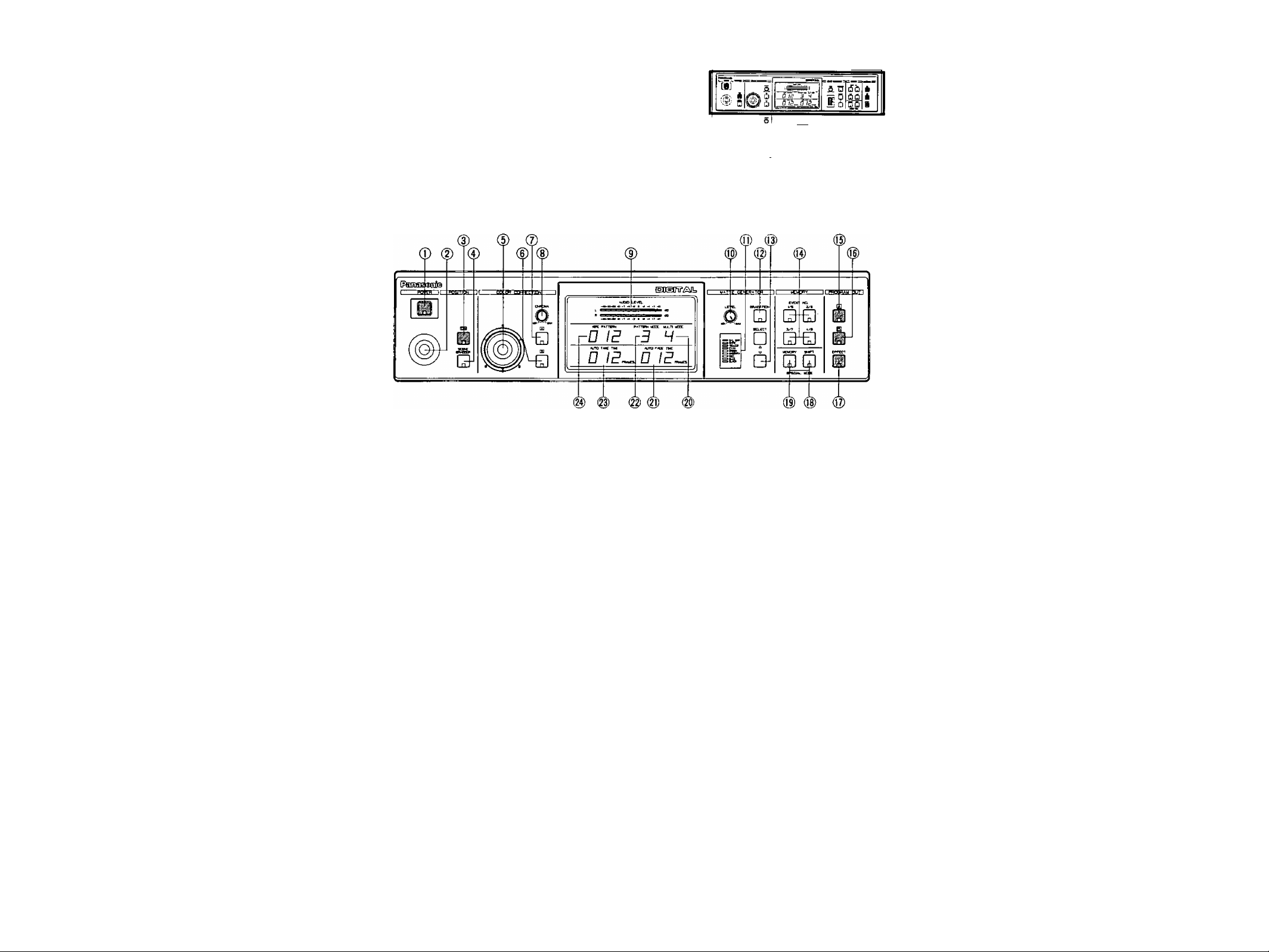
MAJOR OPERATING CONTROLS AND THEIR FUNCTIONS
I
TOP VIEW 1
Power ON/OFF Button (POWER)
Press this button to turn on the power of the unit.
The LED on this button lights and the following LEDs
light up at the same time. C/L BAR on the Matte
Color Indicator (11), Effect-Out Button (17), One-Way
Button (27), Straight Wipe Button (70), Effect ON/OFF
Button (59), Effect-A Button (58), Repeat Effect Button
(54), DSK'A Button (45), Matte Button (47), Wipe Select
Button (74), Source Ion A-bus Button (102), SouCG 2 on
B-Bus Button (101), Audio Follow ON/OFF Button (79)
and Black Fade Button (85). These LED’s light up only
when the Reset ON/OFF Switch (109) is turned on.
Notes:
1. The Main Power Switch (in back) (131) must be on
before the Power ON/OFF Button (1) is pressed
2. When the Editing Controller AG-A800 is used with
WJ-MX50, the power of AG-A800 should be off
first to turn off the power of WJ-MX50. The power
of WJ-MX50 can not be turned off by-itself.
3. Read Note 3 on page 17,
2.
Positioner Joystick
The position of the wipe pattern as selected using the
Square Wipe Button (60) can be freely set using this
Joystick control.
3.
Positioner ON/OFF Button (ON)
This button must be pressed to operate the Positioner
Joystick (2),
4.
Scene Grabber ON/OFF Button (SCENE GRABBER)
The scene wiped by the Square Wipe Button (60) will
be grabbed by pressing this button. The position of this
area can then be changed by operating the Positioner
Joystick (2).
ns nn
^ ^ £ S
iii A
5. RGB Control
This Joystick Control permits you to balance or change
the hue from the images of the Source Video Signal
(either A or B) by moving its position. When' this
Controller is positioned at center, it generates the
original color of the Source Video Signal.
G. Color - B Button (B)
Color correction can be made on the B - bus Source
Video Signal by pressing this button. When you press it
once, the LED starts blinking, the chroma level can be
changed by using the Chroma Level Control (8).
When you press a second time, the LED is continuously
turned on, the hue can be changed by using the RGB
Control (5) in addition to the chroma level by using the
Chroma Level Control (8).
7. Color - A Button (A)
Color correction can be made on the'A - bus Source
Video Signal by pressing this button. When you press it
once, the LED starts blinking, the chroma level can be
changed by using the Chroma Level Control (8).
When you press a second time, the LED is continuously
turned on, the hue can be changed by using the RGB
Control (5) in addition to the chroma level by using the
Chroma Level Control (8).
8. Chroma Level Control (CHROMA)
This Control adjusts the color level of the images from
the Source Video Signal. When this Control is set to
the center position, it generates the original color level
of the Source Video Signal.
Note :
The noise may be recorded on tape when this
control is adjusted to the MAX with excessive
color input signal.
A a .6. A
fiS Q ¿fiiflOflCl
iSi 0 ChQ
I
__
______
■liirr ■ - i
Q_Q_0
*Cha
-A -
Page 6

9. Audio Level Indicator (AUDIO LEVEL)
This Indicator indicates the audio output level of the
Program Out 1 Audio Output Connector {135} and the
Program Out 2 Audio Output Jacks (134).
17. Effect - Out Button (EFFECT)
When this button is pressed, the final video signal whether it is effected or not - will be provided at the
Program Output connector.
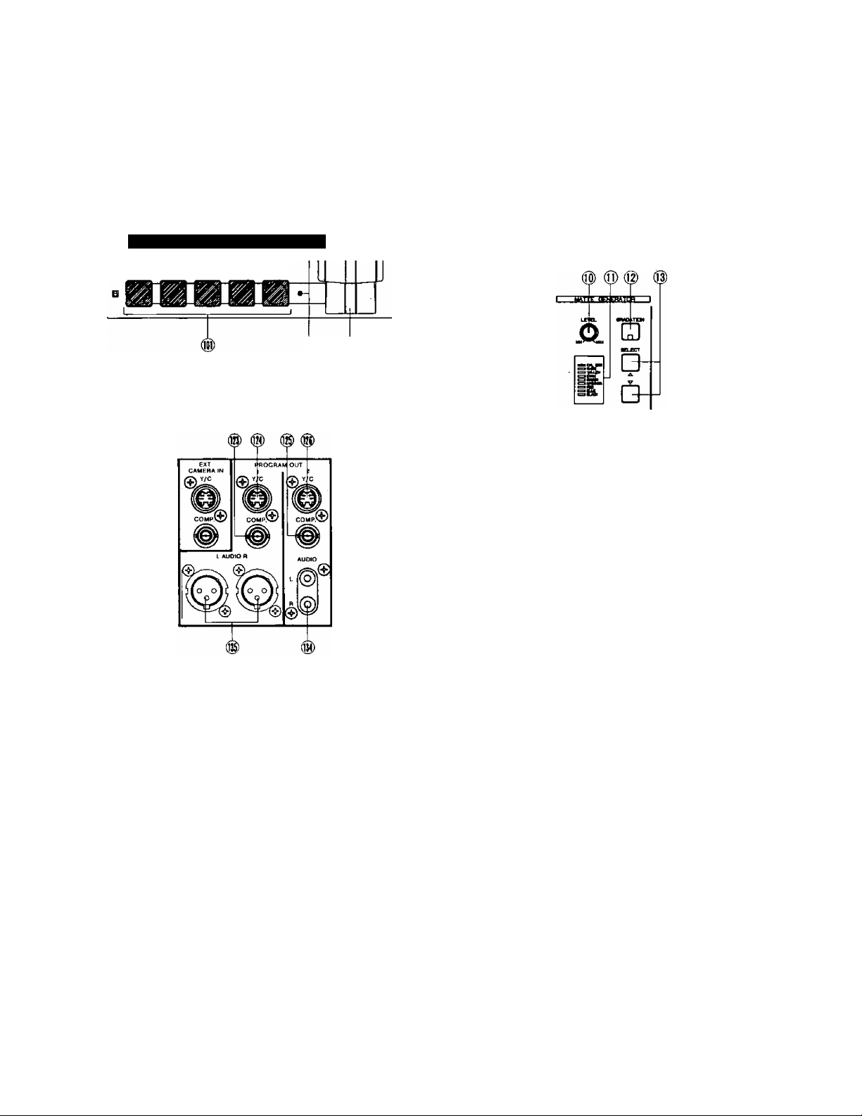
10. Matte Color Control (LEVEL)
The color displayed on the Matte Color Indicator (11)
can be adjusted with this control except C/L BAR.
11. Matte Color Indicator
The Matte Color selected by the Matte Color Selectors
(13) is shown by the appropriate LED.
12. Gradation Button (GRADATION)
When this button is pressed, the Matte color of
the upper portion on the screen is less intense and
g'radually increases to that of the lower portion of the
screen.
13. Matte Color Selectors (SELECT)
Any one of 9 Matte Colors - Color Bar, White, Yellow,
Cyan, Green, Magenta, Red, Blue and Black - can be
selected by repeatedly pressing either of these buttons.
When the SELECT (A) button is pressed, the color
indicated on the Matte Color Indicator (11) changes
from lower to upper. The Black will be selected after
the Color Bar. When the SELECT (V) button is pressed,
the reverse procedure takes place.
14. Event Number Buttons (EVENT NO)
These buttons are used to memorize the present status
of all functions settings on the unit. Also this button can
be used with the Auto Take Button (97) to recall the
memorized status. Each button has 2 memories (by
using Shift Button (18)). Up to 8 memories are availabe
with these 4 buttons.
Note :
Refer to the Shift Button (18) and the Memory Set
Button (19) for selection of preset memory settings.
15. Program Out - A Button (A)
When this button is pressed, the A - bus source signals
which is given Effect by the DIGITAL EFFECT function.
COLOR CORRECTION function, SCENE GRABBER
function, COMPRESSION function or SLIDE function
is provided at the Program Output connectors.
Note:
If the MATTE on the A - bus is pressed, the A - bus
button will begin blinking automatically to show
you which button was selected before.
1G. Program Out - B Button (B)
When this button is pressed, the B - bus source signals
which is given Effect by the DIGITAL EFFECT function,
COLOR CORRECTION function, SCENE GRABBER
function, COMPRESSION function or SLIDE function
is provided at the Program Output connectors.
Note ;
If the MATTE on the B - bus is pressed, the B - bus
button will begin blinking automatically to show
you which button was selected before.
18. Shift Button (SHIFT)
This button will be used when the Event Number
Buttons (14) numbered 5 to 8 are required. However,
in case this button is pressed with the Memory Set
Button (19) simultaneously, the unit then enters the
Special Mode (SPECIAL MODE).
Notice:
(1) Refer to page 35 for details of the Special Mode.
(2) In the Special Mode, the LED on the Shift Button
(18) goes off and the one on the Memory Set
Button (19) starts blinking.
19. Memory Set Button (MEMORY)
This button has 2 functions. In order to activate the
Event Number Buttons (14) to memorize the current
status of the unit, press the Memory Set Button
(19) prior to the Event Number Buttons (14), In
case this button is pressed with the Shift Button
(18) simultaneously (as mentioned previously), the unit
enters the Special Mode.
Notice:
(1) Refer to page 35 for details of the Special Mode,
(2) In Special Mode, the LED on the Shift Button (18)
goes off and the one on the Memory Set Button
(19) starts blinking.
20. Multi Mode Indicator (MULTI MODE)
The number displayed on this indicator shows the mode
of the pattern by pressing the Multi Wipe Button (67).
From 0 to 6 will be indicated
21. Auto Fade Time Indicator (AUTO FADE TIME)
The number on the indicator shows the fading time by
picture frame when adjusting the Auto Fade Transition
Control (91).
From 0 to 510 will be indicated for every 2 frames.
22. Pattern Mode Indicator (PATTERN MODE)
The number on this indicator shows the pattern mode
which is pressed and selected from the Wipe Pattern
Select Buttons number (60), (61), (62), (64), (66), (68) or
(70).
From 1 to 4 will be indicated.
23. Auto Take Time Indicator (AUTO TAKE TIME)
The number on this indicator shows the Auto Take
Time by picture frame when adjusting the Auto Take
Transition Control (90).
From 0 to 510 will be indicated for every 2 frames.
24. Wipe Pattern Number Indicator (WIPE PATTERN)
The number on this indicator shows the wipe pattern
which is generated by the combinations of the Wipe
Pattern Select Buttons number (60), (61), (62), (64), (66),
(68) or (70), and Modify Buttons number (63), (65), (67),
(69) or (71).
Any possible combination from 1 to 255 will be
indicated.
lì
-5-
Page 7
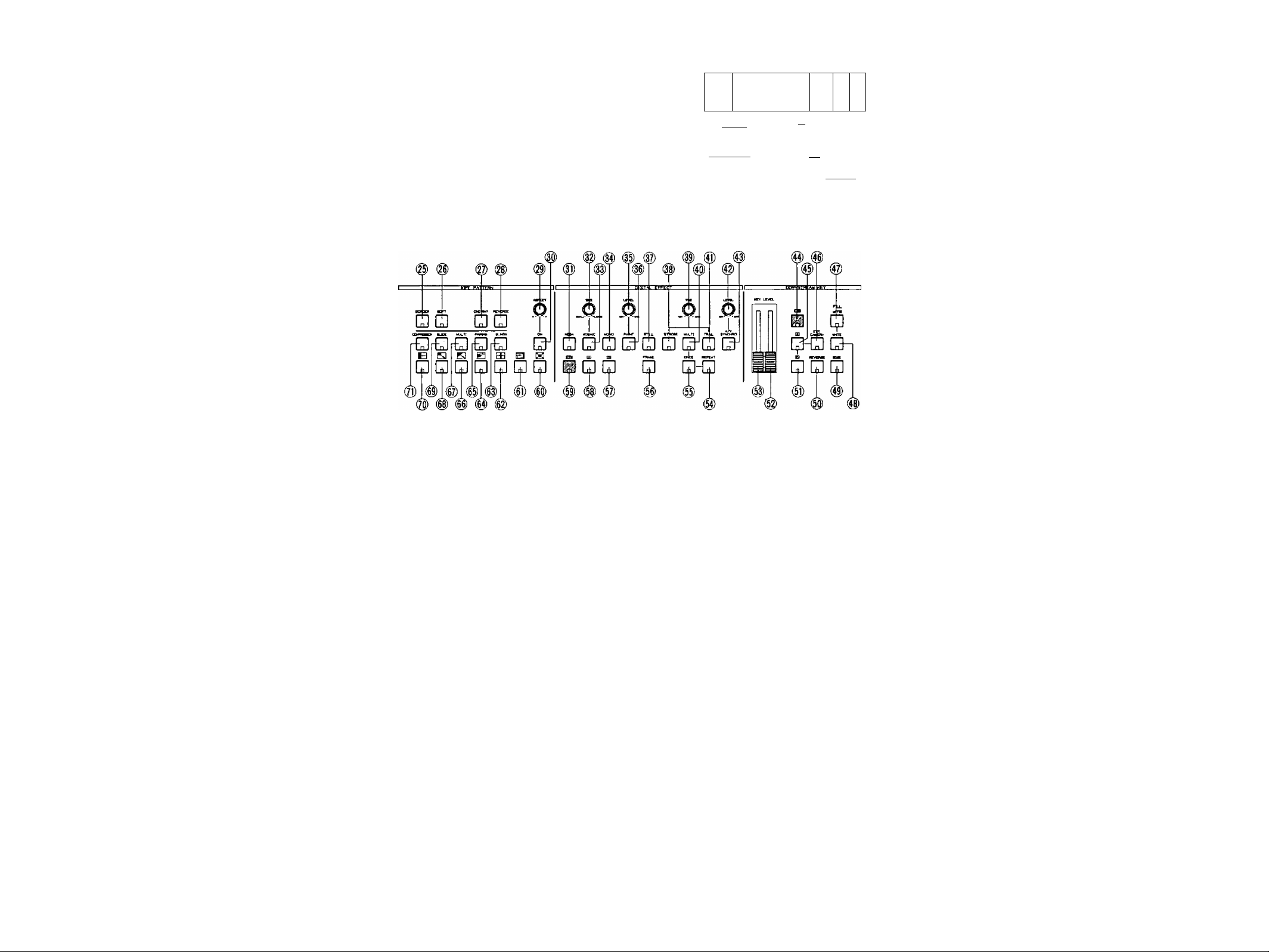
I TOP VIEW 2
i
B
£6 gg Y
Q o□ o
£i0fi3 Cl 35
■ B15^-A
■ Mt
'a 13
-iJ- A A
A (i] Ei] 3 CC
[ j| Q 0
■I B
fjfO
S 0
!lSo§
IB cnci
liiiiiiifMiirii
aBBgg
do
00 A
fDO
■
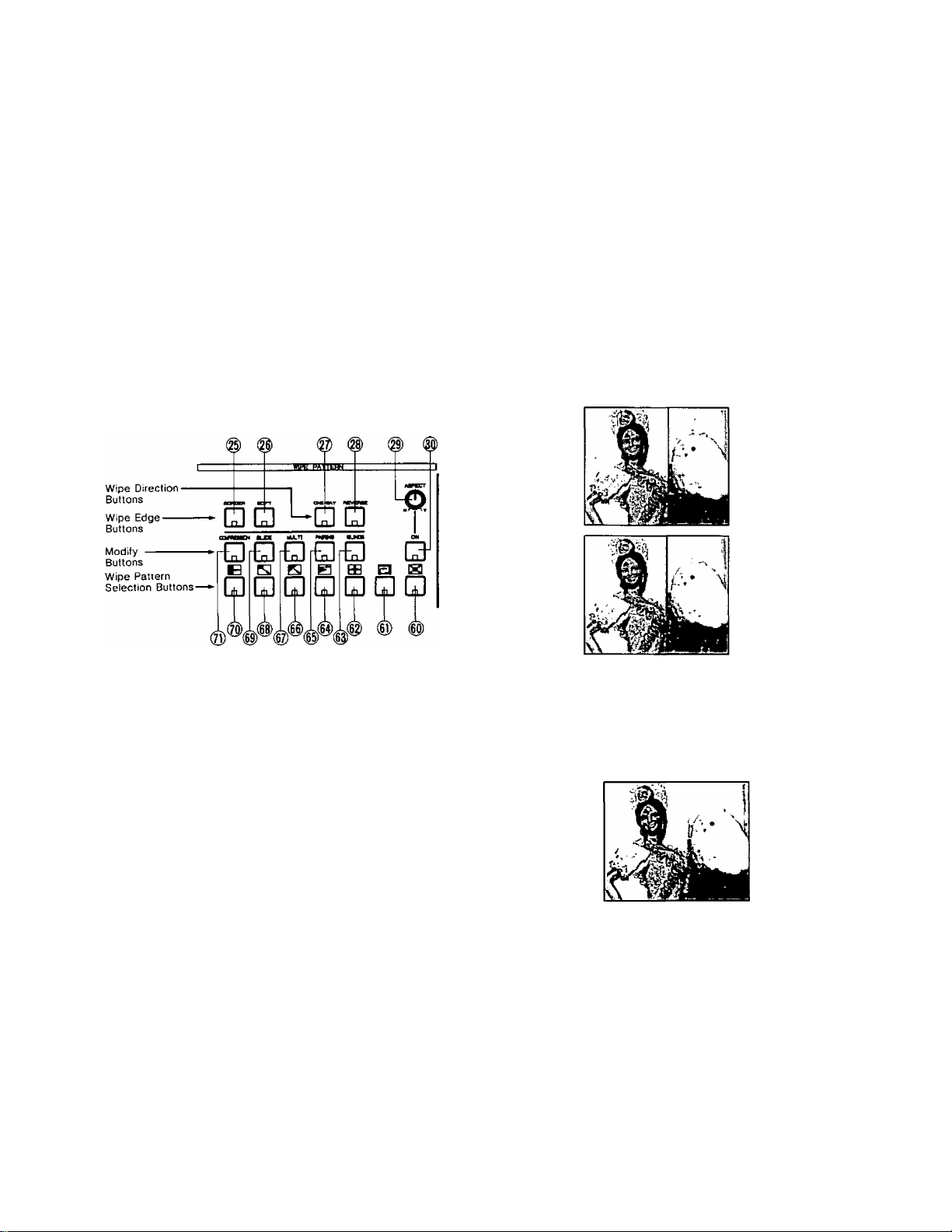
25. Border Button (BORDER)
This button is used for selecting a border wipe edge.
Pressing this button once selects a narrow border.
Pressing this button a second time selects a wide
border. The color of the border is applied from the
complementary color of selected Matte Color.
26. Soft Button (SOFT)
This button is used for making the faint border wipe
edge. Pressing this button once selects a narrow soft
border. Pressing this button a second time selects it a
o
wide soft border. No color is available.
27. One-Way Button (ONE - WAY)
When this button is pressed, the wiping scene moves
one way everytime by changing the Mix/Wipe Lever
(99). Without using this function, the wiping scene
moves alternately by changing the Mix/Wipe Lever (99).
28. Reverse Button (REVERSE)
When this button is pressed, the movement of the wiped
scene will be reversed compared without pressing this
button.
29. Aspect Control (ASPECT)
The aspect ratio, used only when the Square Wipe
Button (60) is selected, can be changed by adjusting
this control. To use this function, the Aspect ON/OFF
Button (30) must be ON.
Note :
The black area will be shown along the image on
the video monitor when the Compression function
is used with it.
30. Aspect ON/OFF Button (ON)
In case the Aspect function is required, this button must
first be pressed.
31. Negative Button (NEGA)
The on-screen image can be transposed to look like a
negative of the visual image by pressing this button.
32. Mosaic Size Control (SIZE)
The size of the pieces of the mosaic pattern can be
adjusted by twisting this control.
33. Mosaic Button (MOSAIC)
By adding small squares in mosaic-like patterns a
design or blurred image can be created. The size
of the mosaic squares can be changed by using the
Mosaic Size Control (32).
34. Mono Color Button (MONO)
When this button is pressed, the Source Video Signal
becomes a monochrome scene. This function has a
priority to the Color Correction function in operation.
35. Paint Control (LEVEL)
The gradation of the paint effect can be changed by
adjusting this control.
36. Paint Button (PAINT)
The image can be transformed to resemble an oil
painting of the video scene by pressing the button.
- 6 -
Page 8

37. Still Button (STILL)
An instant still or frozen image of the video can be’
obtained by pressing this button.
38. Strobe Button (STROBE)
Video frames can be frozen internnittenty, to achieve
a strobe effect, by pressing this button. The strobe
interval can be adjusted by the Effect Interval Timer
(39) from approximately 0.03 seconds to 2.1 seconds .
4G. Ext. Camera Button (EXT. CAMERA)
When this button is pressed, the external camera which
is connected to the External Camera Input (121) or (122)
can be used as the Key-Source Signal.
47. Matte Button (MATTE)
When this button is pressed, the Matte Color generated
in the MATTE GENERATOR will be used as a Key-Fill
Signal which is to be overlaid on the Key-Source Signal.
39. Effect Interval Timer (TIME)
The time of interval for the Strobe effect, Multi effect
and Trail effect can be adjusted by this timer. Also this
timer works with the A/V Synchro function. In this case,
the A/V Synchro interval applies to the Strobe effect.
40. Multi Button (MULTI)
The video image on the monitor TV becomes multiple
video images by pressing this button. When you press it
first, 4-images are displayed. The second press makes
it 9-images and the third press makes it 16-images.
The fourth press returns the screen to a single image
screen. The trail interval can be changed by the Effect
Interval Timer (39) from approximately 0.06 seconds to
2.1 seconds.
41. Trail Button (TRAIL)
The compressed video image trails one after another
from small to larger and larger video images up to
a maximum of 16 images. The start position can
be selected by the Positioner Joystick (2) either to
start from upper right or upper left. The trail interval
can be changed by the Effect Interval Timer (39) from
approximately 0.06 seconds to 2.1 seconds.
42. A/V Synchro Control (LEVEL)
This control adjusts the trigger sensitivity of the A/V
Synchro. When this control is turned to the MAX
position, the A/V Synchro will be triggered by (a higher
threshold) high level sounds. When this control is turned
to the MIN position, the A/V Synchro will be triggered
by (a lower threshold) low level sounds.
48. White Button (WHITE)
When this button is pressed, the white color will be
used as a Key-Fill Signal which is to be overlaid on the
Key-Source Signal.
49. Edge Button (EDGE)
This button is used to edge on the Downstream Keyed
images. Two types (shadow, border) and five kinds of
edges are available by pressing this button repeatedly.
Notes ;
1. When the Downstream Keyed images are white,
you can color the edge to any one of 9 colors,
solid or graded by pressing the Gradation Button
(12) and the Matte Color Selector (13),
2. When the Matte Colored Downstream Keyed
images are used, the edge color is always black.
50. Key Reverse Button (REVERSE)
The polarity of the Downstreamed Keyed Images will
be reversed by pressing this button,
51. DSK-B Button (B)
When this button is pressed, the Source Video Signal
on the B-Bus will be the Key-Source Signal.
52. High Level Key Slide Control (KEY LEVEL)
This slide control is used to adjust the sensitivity of the
luminance level of the Key signal for higher level,
53. Low Level Key Slide Control (KEY LEVEL)
This slide control is used to adjust the sensitivity of the
luminance level of the Key signal for tower level,
43. A/V Synchro Button (A/V SYNCHRO)
Any combination of the digital effects (Nega, Mosaic,
Mono, Paint, Still or Strobe) can be synchronized to
pulse with certain levels of accompanying music or
sound supplied to the WJ-MX50.
44. DSKON/OFF Button (ON)
This button is pressed to activate the Downstream Key
(DSK) effect.
45. DSK-A Button (A)
When this button is pressed, the Source Video Signal
on the A-Bus will be the Key-Source Signal.
54. Repeat Effect Button (REPEAT)
Each of the multiple video images will be scanned one
after another repeatedly by pressing this button.
55. Once Only Button (ONCE)
Each of the multiple video images will be scanned one
time only by pressing this button, it will be frozen after
that.
56. Frame Button (FRAME)
When this button is pressed the Digital Effected Image
is reproduced as a frame video image. This feature is
applied to Still, Strobe, Multi and Trail functions. And
this button is used to remove the image vibration.
- 7 -
Page 9

Note :
The diiference between on and off of this button.
FRAME BUTTON
Output Signal
Resolution
68. Corner Wipe Button
The video scene is wiped with a square shape from the
corner of the monitor screen. Four kinds of patterns
are available.
ON
OFF
2-field Standard
1 -field
Reduced
57. Etfect-B Button (B)
The Source Video Signal on B-bus will receive the
Digital Effect by pressing this button (if Effect ON/OFF
Button (59) is first pressed).
58. Effect A-Button (A)
The Source Video Signal on A-bus will receive the
Digital Effect by pressing this button (if Effect ON/OFF
Button (59) is first pressed),
59. Effect ON/OFF Button (ON)
The selected Digital Effect function becomes operative
by pressing this button.
60. Square Wipe Button
Four wipe patterns can be selected by pressing this
button repeatedly • • • circle, oval, square and diamond.
The Aspect Control (29) or the Positioner Joystick (2)
can be used with these patterns,
61. Mosaic Wipe Button
The wiping becomes a mosaic-like pattern by pressing
this button. Four kinds of pattern are available by
repeatedly pressing this button.
69. Slide Button (SLIDE)
The wiped scene slides into the monitor screen by
pressing this button once. Both wiped scenes slide in
and out by pressing this button a second time.
70.
Straight Wipe Button
The video scene is wiped with a straight line,
patterns are available.
71.
Compression Button (COMPRESSION)
The compressed video scene is wiped into the monitor
screen by pressing this button once. The compressed
video scenes are wiped in and out of the monitor
screen by pressing this button a second time.
Four
62. Split Wipe Button
The video scene is split from the center of the image
by pressing this button. Three kinds of patterns aie
available by repeatedly pressing this button.
63. Blinds Wipe Button (BLINDS)
The video scene is wiped in a blinds pattern. Several
wipe combinations using buttons (62), (64), (66), (68)
and (70) are operative with this button.
64. Triangle Wipe Button
The video scene is wiped with a triangle shape. Four
patterns are available.
65., Pairing Wipe Button (PAIRING)
A paired wipe scene can be obtained by pressing this
button. The wipe buttons of (64), (66), (68) and (70) are
operative with this button.
66. Diagonal Wipe Button
The video scene is wiped with a diagonal shape. Four
patterns are available.
67. Multi Wipe Button (MULTI)
The wiped pattern can be multipled by pressing this
button repeatedly. The effect of the multiplication
depends on the wiped pattern.
-8-
Page 10
I
TOP VIEW 3
# (§) ®
...
--------
[D
/S', i
W f5
5 o_Q S I
□ S â □ â
i-Bassa^’ ?.(iô-?¡•mw^TTri ■'- '■
.....
f ~i
S.
1 dTe ~h~ *
^ Ô. .0. 5.
- 1 _ i _
Q D Q D D n D D D
■*■ QÛQ
:^£^0^3
№ Ù
ÛÛ
nn
¡^0
É 0
CÆO
itinn
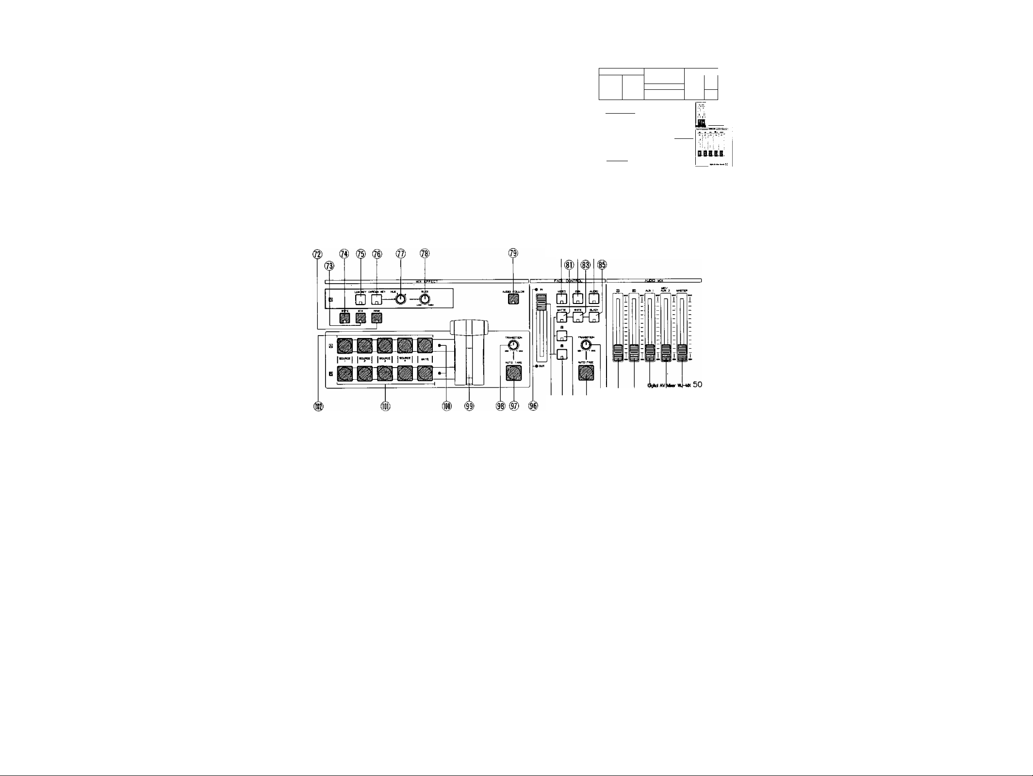
72. NAM Select Button (NAM)
NAM (Non Additive Mix) effect is obtained by pressing
this button and the Mix/Wipe Lever (99) is to be
positioned at center. The darker area on the B-bus
image and the A-bus image are replaced at relative
levels by the lighter areas of each other, i.e. the
stronger (lighter) images from either input replace the
weaker (darker) ones.
73. Mix Select Button (MIX)
This button is pressed to obtain a Mix Effect between
the A-bus Source Video Signal and the B - bus Source
Video Signal.
74. Wipe Select Button (WIPE)
This button is pressed to obtain a Wipe effect between
the A-bus Source Video Signal and the B-bus Source
Video Signal using the settings of the Wipe Pattern
Select Buttons.
(¿) ¿) # (@) @) ®
76. Chroma Key Select Button (CHROMA KEY)
The Chroma Key effect is obtained by pressing this
button and the adjustment of the Hue Control (77) and
Slice Control (78). The B-bus signal must be the Key
signal.
77. Hue Control (HUE)
This control is used to adjust the Hue of the Chroma
Key effect.
78. Slice Control (SLICE)
This control is used to adjust the slice level of the
luminance signal for the Luminance Key effect or the
chroma signal for the Chroma Key effect.
79. Audio Follow Button (AUDIO FOLLOW)
When this button is pressed, the audio on the A-bus
and B“bus can be changed according to the relative
percentage position of the Mix/Wipe Lever (99).
75. Luminance Key Select Button (LUM KEY)
The Luminance Key effect is obtained by pressing this
button and the adjustment of the Slice Control (78). The
B - bus signal must be the key signal.
80. Video Fade Button (VIDEO)
When this button is pressed, the Wiped or Mixed video
signal will fade-in or fade-out by using the Fade Control
(95).
- 9 -
Page 11

81. Matte Fade Button (MATTE)
The video fade signal is faded out to the selected Matte
Color by pressing this button.
94. B-bus Fade Button (B)
The video fade signal is faded out to the B-bus video
signal by pressing this button.
82. DSK Fade Button (OSK)
When this button is pressed, the Dovwnstream Keyed
signal will fade-in or fade-out by using the Fade Control
(95).
83. White Fade Button (WHITE)
The video fade signal is faded out to White by pressing
this button.
84. Audio Fade Button (AUDIO)
When this button is pressed, the audio will fade-in or
fade-out by using the Fade Control (95).
85. Black Fade Button (BLACK)
The video fade signal is faded out to Black by pressing
this button.
86. Master Audio Fader (MASTER)
The total audio level of the mixed audio signals is
adjusted by sliding this fader.
87. Mic/Aux-2 Audio Fader (MIC/AUX2)
The audio level connected to the Microphone Jack
(106) or the Auxiliary Audio Input-2 Jack (136) can be
adjusted by sliding this fader. Select the Mic or Aux-2
audio signal by the Mic/Aux-2 Switch.(105).
88. Aux-1 Audio Fader (AUX1)
The audio level connected to the Auxiliary Audio Input-1
Jack (137) can be adjusted by sliding this fader.
89. B-bus Audio fader (B)
The audio level from the B-bus source inputs can be
adjusted by sliding ttiis fader.
90. A-bus Audio Fader (A)
The audio level from the A-bus source inputs can be
adjusted by sliding this fader.
91. Auto Fade Transition Control (TRANSITION)
This control adjusts the automatic fading time from 0 to
510 frames for every 2 frames.
This amount is then displayed on the "Auto Fade Time
Indicator" (21).
95. Fade Control
The fade-in and fade-out can be rfianually controlled
by using this control.
96. Fade LED (iN/OUT)
When the IN (OUT) LED is continuously turned on, the
fade is In (Out) situation. When the IN (OUT) LED is
blinking, the fade-in (fade-out) is currently incomplete.
97. Auto Take Button (AUTO TAKE)
The Auto Take effect - Automatic Wipe/Mix/NAM - can
be executed by pressing this button. This button lights
during the Auto-Take interval.
98. Auto Take Transition Control (TRANSITION)
The Auto Take interval time can be adjusted by this
control from 0 to 510 frames for every 2 frames.
99. Mix/Wipe Lever
In the wipe mode, manually moving this lever between
the A-bus and B-bus will increase the relative portion
of each bus signal, according to the option selected. In
the mix mode, the audio/video are together switched
between A-bus and B-bus.
100. Mix/Wipe LED
When the A-bus (or B-bus) LED is continuously turned
on, the Wipe/Mix/NAM is A-bus (or B-bus) situation.
When the A-bus (or B-bus) LED is blinking, the
Wipe/Mix/NAM effect is only partially completed on
the A-bus (or B-bus) side.
101. B-bus Buttons (8)
These buttons are used to select the desired
audio/video signals allocated to the B-bus input. The
Source 1/2/3/4 corresponds to the Source 1/2/3/4
audio/video inputs on the rear panel of the instrument.
102. A-bus Buttons (A)
These buttons are used to select the desired
audio/video signals allocated to the A-bus input. The
Source 1/2/3/4 corresponds to the Source 1/2/3/4
audio/video inputs on the rear panel-of the instrument.
92. Auto Fade Button (AUTO FADE)
When this button is pressed, the automatic fade
sequence for the selected input(s) begins, with the
time set by the Auto Fade Transition Control (91), This
button remains tit during Auto-fading.
93. A-bus Fade Button (A)
The video fade signal is faded out to the A-bus video
signal by pressing this button.
- 10 -
Page 12
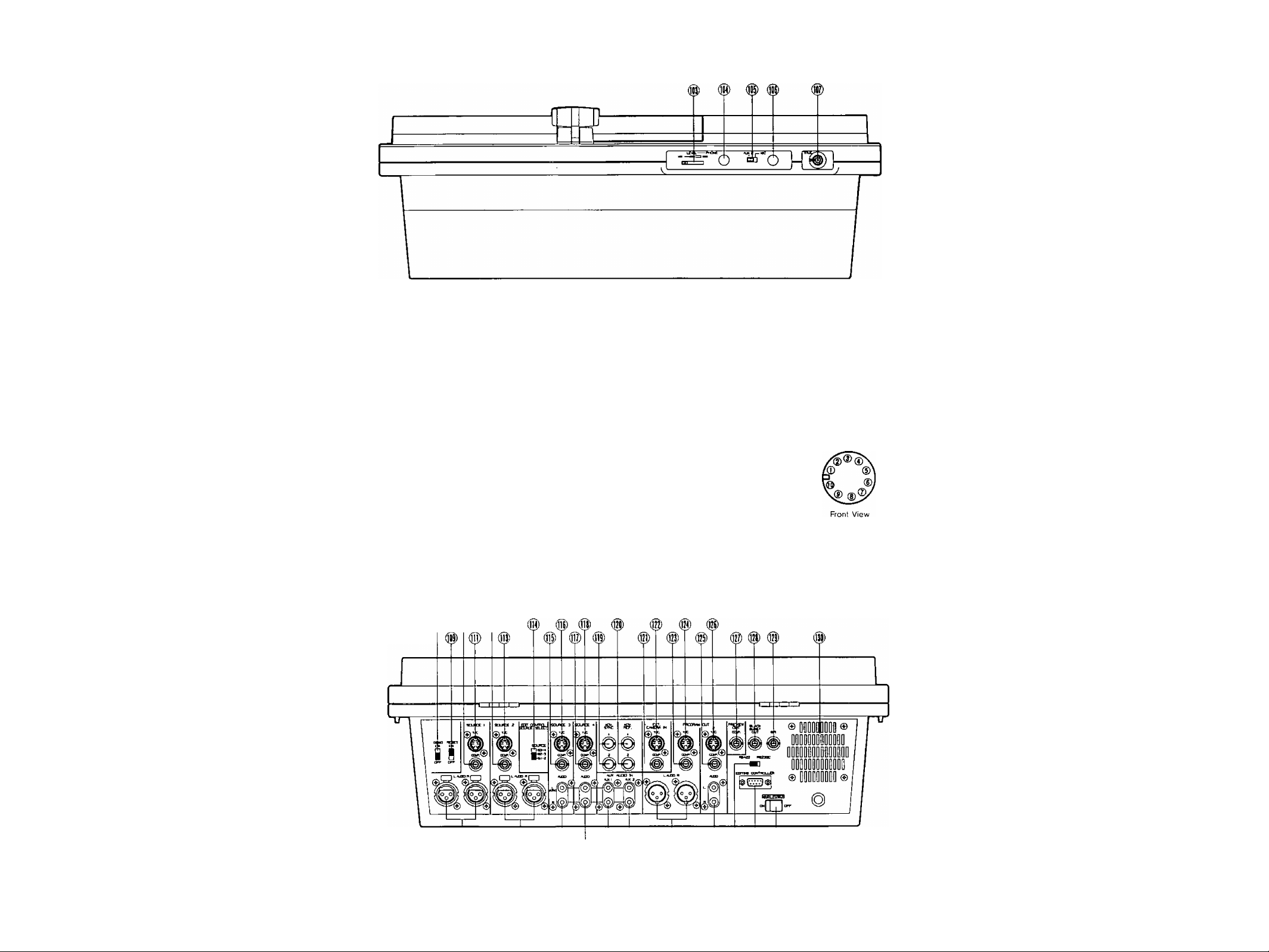
FRONT VIEW
103. Headphone Level Control (LEVEL)
The audio level of the headphone can be adjusted with
this control,
104. Headphone Jack (PHONES)
Optional headphone can be connected to this jack.
105. Mic/Aux-2 Switch (AUX 2/MIC)
When the Mic/Aux-2 Audio Fader (87) is desired, select
either Mic or Aux-2 with this switch.
106. Microphone Jack (MIC)
Optional microphone can be connected to this jack.
REAR VIEW
® ® 0)
107. Title Input Connector (TITLE)
This connector is used to connect the optional
Character Generator WJ-KB50 (recommended).
The pin numbers are stated below.
Character IN
(1)
Not used
(2)
Ground
(3)
Not used
(4)
Sync out
(5)
{6}
(7)
(8 )
(9)
Not used
Ground
+9V OUT
Ground
TITLE
(10): ID
_ 11 _
Page 13

108. Demo ON/OFF Switch (DEMO ON/OFF)
When this switch is in the ON position, a
preprogrammed mixer features demonstration takes
place.
115. Source 3 COMP. Input Connector
(SOURCE3/COMP.)
This connector accepts a 1.0 Vp-p/75 ohms composite
video signal.
109. Reset ON/OFF Switch (RESET ON/OFF)
In case the power of this unit is turned on while this
switch is in the ON position, the LED’s on the panel
light up as the factory preset. In case the power of this
unit is turned on while this switch is in the OFF position,
the LED's on the panel light up returnning to how they
were. Refer to Note 3 on page 17.
110. Sourcel COMP. Input Connector
(SOURCE1/COMP.)
This connector accepts a 1.0 Vp-p/75 ohms composite
video signal.
111. Sourcel Y/C Input Connector (SOURCE 1-Y/C)
This connector accepts the S-Video signal.
Note:
This input has a priority over that of the COMP,
Connector in the Source 1. If the S-Video signal
and the composite signal are both supplied to the
Sourcel at the same time, only the S-Video signal
is used as a Sourcel Video signal.
112. Source 2 COMP. Input Connector
(SOURCE2/COMP.)
This connector accepts a 1.0 Vp-p/75 ohms composite
video signal.
113. Source 2 Y/C Input Connector (SOURCE2-Y/C)
This connector accepts the S-Video signal.
Note:
This input has a priority over that of the COMP.
Connector in the Source 2. If the S-Video signal
and the composite signal are both supplied to the
Source 2 at the same time, only the S-Video signal
is used as a Source 2 Video signal.
114. Source Selection Switch
(EDIT CONTROL SOURCE SELECT, SOURCE)
This switch is used to choose between the Source
signals for the Editing Controller AG-A800. The relation
between this switch and the source selection switches
(P1, P2, AUX) on the AG-A800 is as follows.
WJ-MX50 SOURCE AG-A800
P1 P2 AUX
SI-2 Source 1 Source 2 Source 3
S2-3 Source 2
S3-4 Source 3 Source 4 Source 1
Source 3 Source 4
116. Source 3 Y/C Input Connector (SOURCE4-Y/C)
This connector accepts the S-Video signal.
Note:
This input has a priority to that of COMP.
Connector in the Source 3. If the S-Video signal
and the composite signal are both supplied to the
Source 3 at the same time, only the S-Video signal
is used as a Source 3 Video signal.
117. Source 4 COMP. Input Connector
(SOURCE4/COMP.)
This connector accepts a 1.0 Vp-p/75 ohms composite
video signal.
118. Source 4 Y/C Input Connector (SOURCE3-Y/C)
This connector accepts the S-Video signal.
Note:
This input has a priority to that of COMP.
Connector in the Source 4. If the S-Video signal
and the composite signal are both supplied to the
Source 4 at the same time, only the S-Video signal
is used a Source 4 Video signal
119. Advance Sync Output Connectors (ADV SYNC)
In the A/B Roll Editing System, the Advance Sync signal
from this connector should be supplied to the playback
VTR's which do not have the Time Base Corrector
(T.B.C.) inside.
Note:
The enough editing accuracy may not be obtained
without this signal. This signal is necessary for the
Compression function and Trail function when it is
recorded on the VTR,
120. Advance Reference Output Connectors
(ADV REF)
In the A/B Roll Editing System, the Advance Reference
Signal from this connector should be supplied to the
playback VTR's which have the Time Base Corrector
(T.B.C.) inside (or AUX video source).
Note:
The enough editing accuracy may not be obtained
without this signal. This signal is necessary for the
Compression function and Trail function when it is
recorded on the VTR,
121. External COMP. Input Connector
(EXT CAMERA IN/COMP.)
The external camera to be used as a Key Source is
connected to this connector when the camera has the
composite video signal.
Example:
If this switch is in the Si-2 position, Sourcel is
selected when Pi button is pressed.
122. External Y/C Input Connector
(EXT CAMERA IN/Y/C)
The external camera to be used as a Key Source is
connected to this connector when the camera has a
S-Video Signal.
- 12 -
Page 14

123. Program Out-1 COMP. Output Connector
(PROGRAM OUT 1/COMP.)
The Program Output Signal-lof the composite video
signal is provided via this connector,
134. Program Out-2 Audio Output Jacks
(PROGRAM OUT 2/AUDIO, L/R)
The audio output signals of R-channel and L-channel
on the Program Output 2 are provided via these jacks.
124. Program Out-1 Y/C Output Connector
(PROGRAM OUT 1/Y/C)
The Program Output Signal-1 of the S-Video signal is
provided via this connector.
125. Program Out-2 COMP. Output Connector
(PROGRAM OUT 2/COMP.)
The Program Output Signai-2 of the composite video
signal is provided via this connector,
126. Program Out-2 Y/C Output Connector
(PROGRAM OUT 2/Y/C)
The Program Output Signal-2 of the S-Video signal is
provided via this connector.
127. Preview Output Connector
(PREVIEW OUT, COMP.)
The effected video'of the composite video signal is
obtained at this connector regardless of the selection
of the Program Out Buttons (15), (16), (17).
128. Black Burst Output Connector
(BLACK BURST OUT)
The Black Burst Signal for use with system
synchronization is provided via this connectorto the
Editing Controller.
129. GPI Input Connector (GPl)
In the A/B Roll Editing System, the GPI signal (General
Purpose Interface) may be used in order to make
an interface between the WJ-MX50 and the Editing
Controller.
130. Cooling Fan
131. Main Power Switch (MAIM POWER)
The unit becames stand-by mode by turning on this
switch. Unless this switch is turned on, the unit will not
be on even if the (front panel) Power ON/OFF Button
(1) is pressed.
Note :
The unit becomes on without pressing Power
ON/OFF Switch (1) by turning Main Power Switch
(131) on if the Reset ON/OFF Switch (109) had
been set to the OFF position. This takes place
leaving the Main Power Switch (131) off for more
than a few days.
132. Editing Control Connector
(EDITING CONTROLLER)
This connector is used for connecting with the Editing
Controller AG-ABOO or the Modem Unit.
135. Program Out-1 Audio Output Connectors
(PROGRAM OUT 1/AUDIO L/R)
The audio output signals of R-channel and L-channel
on the Program Output 1 are provided via these
XLR-connectors.
136. Auxiliary Audio Input-2 Jacks
(AUX AUDIO IN,AUX2)
The auxiliary audio input 2 signal can be inputted
via these jacks. When the audio is supplied to the
L-channel, this audio is supplied to the R-channel
(mono-mode) internally. When the audio is also
supplied to the R-channel, this audio is used for the
R-channel only.
137. Auxiliary Audio Input-1 Jacks
(AUX AUDIO IN.AUXI)
The auxiliary audio input 1 signal can be inputted
via these jacks. When the audio is supplied to the
L-channel, this audio is supplied to the R-channel
(mono-mode) internally. When the audio is also
supplied to the R-channel, this audio is used for the
R-channel only,
138. Source 4 Audio input Jacks
(SOURCE 4/AUDlO L/R)
Source 4 Audio Input signal can be supplied via these
jacks. When the audio is supplied to the L-channel,
this audio is supplied to the R-channel (mono-mode)
internally. When the audio is also supplied to the
R-channel, this audio is used for the R-channel only.
139. Source 3 Audio Input Jacks
(SOURCE 3/AUDlO IN, AUX1)
Source’3 Audio Input signal can be supplied via these
jacks. When the audio is supplied to the L-channel, this
audio is also supplied to the R-channel (mono-mode)
internally. When the audio is also supplied to the
R-channel, this audio is used for the R-channel only,
140. Source 2 Audio Input Connectors
(SOURCE 2/AUDIO L/R)
The Source 2 Audio Input Signal can be supplied via
these XLR-connectors.
141. Sourcel Audio Input Connectors
(SOURCE 1/AUDIO L/R)
The Sourcel Audio Input Signal can be supplied via
these XLR-connectors.
133. RS422/RS232C Selection Switch
(RS422/RS232C)
When using an external product such as the Editing
Controller AG-ABOO or the Modem Unit, this switch is
used to make the selection. In the case of the Editing
Controller, turn this switch to the RS422 position. In the
case of the Modem Unit, turn this switch to the RS232C
position.
- 13 -
Page 15
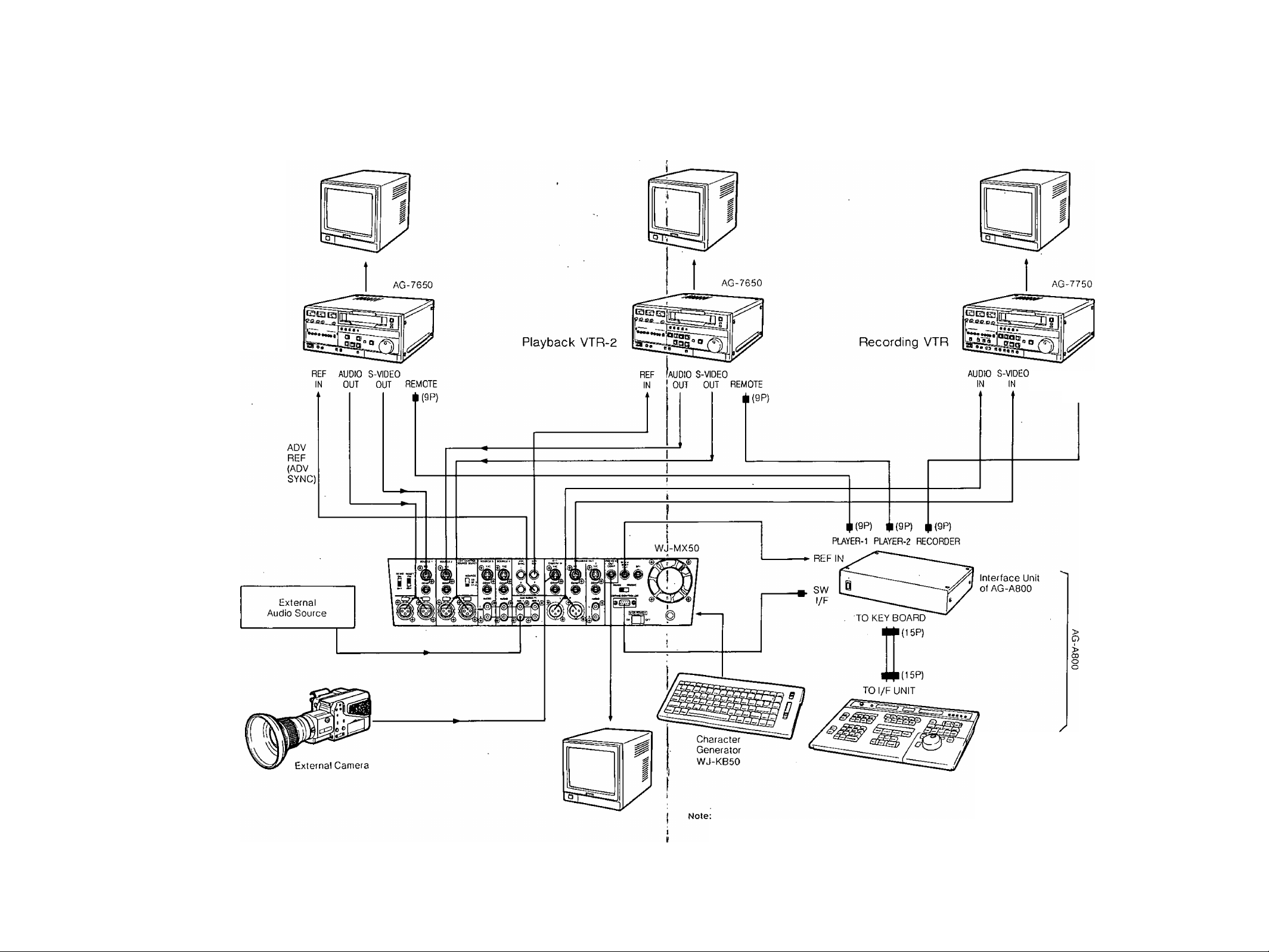
SYSTEM CONNECTION
This system diagram shows the example of Panasonic A/B
ROLL EDITING SYSTEM with 2 Playback VTR's, 1 Recording
VTRand 1 Editing Controller AG-A800.
Playback VTR-1
For the details of operations, setting up of controls and
connections for the VTR's, refer to the corresponding
operating manuals.
REMOTE
*{9P)
- 14 -
Editing Controller
AG-A800
The ADV REF, ADV SYNC or BLACK BURST signal should be used.
The enough editing accuracy may not be obtained without this signal. This signal is necessary for the Compression function and Trail
function when it is recorded on the VTR,
- 15 -
Page 16

The following models {or equivalents} are recommended in
this system. The S-Video signal and balanced audio signal
are also recommended to use obtaining a quality edited
outputs.
Digital AV Mixer: WJ-MX50
Character Generator: WJ-KB50
External Camera ; WV-D5100
Playback VTR: AG-7650
Recording VTR : AG-7750
Editing Controller; AG-A800
Monitor TV
(I) Connect the coaxial cables between the Advance
Reference Output Connectors (130) on the WJ-MX50
and the REF-IN connector on both Playback VTR-1 and
-2.
{2} Connect the audio cables between the Source 1 Audio
Input Conector (141) /Source 2 Audio Input Connector
(140)/Program Out-1 Audio Output Connector (135) on
the WJ-MX50 and the.AUDIO OUT connector/AUDIO
IN connector on the PlaybackVTR-1/Playback
VTR-2/Recording VTR respectively.
(3) Set the Source Selection Switch (114)onthe WJ-MX50
to the Si -2 position.
(4) Connect the control cables between the
PLAYER-1/PLAYER-2/RECORDER connectors on the
Interface Unit of AG-A800 and the REMOTE connector
on the Playback VTR-1/Playback VTR-2/Recording
VTR respectively.
(5) Connect the S-Video Cables between the Source 1
Y/C Input Connector (111)/Source 2 Y/C Connector
(113)/Program Out-1 Y/C Output Connector (124)
on the WJ-MX50 and the S-VIDEO OUT/S-VIDEO
IN connectors on the Playback VTR-1 /Playback
VTR-2/Recording VTR respectively.
(6) Connect the coaxial cable between the Black Burst
Output Connector (128) on the WJ-MX50 and the REF
IN connector on the Interface Unit of AG-A800.
(7) Connect the control cable between the Editing Control
Connector (132) and the SW l/F connector on the
interface Unit of AG-A-800.
(8) Connect the control cable between the TO l/F UNIT
connector on the AG-A800 and the TO KEY BOARD
connector on the Interface Unit of AG-A800.
(9) Connect the S-Video Cable between the S-Video
Output Connector on the WV-D5100 and the External
Y/C. Input Connector (122) on the WJ-MX50.
(10) Connect the coaxial cable between the Preview Output
Connector (127) on the WJ-MX50 and the Video Input
Connector on the Monitor TV.
(II) Connect the coaxial cables between the VIDEO
OUT connectors on the Plyaback VTR-1/Playback
VTR-2/Recording VTR and the Video Input Connectors
on the Monitor TV respectively.
(12) Connect the audio cable between the Audio Output on
the External Audio Source and the Auxiliary Audio Input
1 Jacks (137) on the \WJ-MX50.
OPERATION
A. Pre-operational setup
A-1. Power
1. Turn on the MAIN POWER Switch (131) located on the
rear panel. The unit is now in stand-by mode. No
operations can be executed yet.
Press the POWER Button (1) on the operation panel.
The unit is now in operation mode and the Cooling Fan
(130) located on the rear panel starts to rotate. The
LED's on the operation panel light up as shown if the
RESET Switch (109) was already in the ON position.
Notes:
1. If you do not use the unit for an extended period
ot time or to shut off the power completely, switch
off the MAIN POWER Switch (131).
2.
If the Cooling Fan (130) does not rotate, turn off
and disconnect the AC power cord. Call service
personnel before attempting further use.
The power of WJ-MX50 can be turned on from
3.
the Stand-by mode by turning on the power of
AG-A800. In this case the LED of the Mix Select
Button (73) turns on instead of the Wipe Select
Button (74).
A-2. RESETSwitCh
1. ON position • • ■ Factory preset operation mode
It is recommended to normally keep the RESET Switch
(109) in the ON position. It would be helpful in case of
unexpected operational failure.
2. OFF position • ■ ■ Field Preset operation mode
The status of the operation mode will be remembered
when the power of the unit is turned off. And this
status, without Still, Strobe and Special function, is
later recalled when the power is restored.
A-3. DEMO Switch
1. ON position
The preprogrammed demonstration of the built-in
Effect functions of the WJ-MX50 will be automatically
displayed on an attached video monitor.
Note:
This feature is useful for demonstrating functions
to a new user to help familiarize him/herself with
the unit.
2. OFF position
The unit reverts to standard operation mode,
This
switch is normally set to the OFF position.
A-4. Confirm that the unit is in the operation mode. Then
set up the operation panel as mentioned in the next
operating procedure.
- 16 -
- 17 -
Page 17
B. Basic Operation-1 B-1. Input/Output Selection
1. Source Selector
The audio/video signal to be inputted for effect is
selected from the respective options on the A-bus and
B-bus, The selected audio will be controlled by the
AUDIO MIX for the respective A-bus/B-bus audio.
l-T-l l”î“l l”î“l l“î“l l-l
2. Program Out Selection
Note:
The A-bus or B-bus video signal sent out from
the PROGRAM OUT connecctors {123)-(126) wilt
be effected by the Color Correction, Digital Effect,
Position, Downstream Key, Mix Effect and Fade
Control. So do not add these effects to the video
if you want to see the original source video signal.
B-2. Matte
The Matte Color produced by the MATTE GENERATOR
has 9 colors to choose from : Color Bar (C/L BAR),
White, Yellow, Cyan, Green, Magenta,. Red, Blue and
Black.
The audio/video signal to be sent out to the PROGRAM
OUT-1, -2 connectors (123) (124) (125) (126) (134) and
(135) is selected by the appropriate PROGRAM OUT
Buttons (15) (16) (17).
In case the Source Video Signal from the A-bus is to be
sent out directly, press the PROGRAM OUT A Button
(15) . (The Matte Signal will not be sent out. The Source
Video whose button is blinking is sent out instead.) As
for the audio, the mixed audios of A-bus Fader (90),
AUX1 Fader (88) and AUX2 Fader (87) will be sent out.
In case the Source Video Signal from the B-bus is to
be fed out directly, press the PROGRAM OUT B Button
(16) . (The Matte Signal will not be sent out. The Source
Video whose button is blinking is sent out instead.) As
for the audio, the mixed audios of B-bus Fader (89),
AUX1 Fader (88) and AUX2 Fader (87) will be sent out.
In case the (operation panel processed) effected video
signal is to be sent out, press the EFFECT Button (17).
As for the audio, the mixed audios (all under the Master
Audio) in the AUDIO MIX is sent out.
To select the (background) matte color, press either
SELECT Button (13) until reaching the desired color.
The selected color is then indicated by the LED on the
Matte Color Indicator (11).
To change the chroma level of the selected matte color,
adjust the Matte Color Control (10). The C/L BAR and
BLACK will not be changed. In case the WHITE is
selected, the brightness changes from black to white.
When the GRADATION Button (12) is pressed, the Matte
Color is gradated accordingly (per the Matte Color
Control) from the top to the bottom.
Note:
When the Matte Color is selected by the Source
Selector, it can be used as an alternate source
signal for the WIPE (74), MIX (73) and NAM (72)
functions. However the Matte color can not be
used in the following effect operation. In these
cases, the Source Video Signal on the blinking
source button instead of the Matte Color will be
displayed on the monitor automatically.
1. LUM KEY (75) effect
2. CHROMA KEY (76) effect
3. ‘ DOWN STREAM KEY effect
4. FADE CONTROL effect
- 18 -
Page 18

B-3. Audio Mixer
There are 7 audio source inputs on the WJ-MX50 the Source 1 /2/3/4, 2 auxiliary audio inputs (AUX1,2}
and the external microphone. Each audio level can be
adjusted independently by the audio faders.
The EFFECT Button (17) must be on to have the mixed
audio outputs as combined in Audio Mix.
• When the AUX2 audio (instead of external microphone)
is to be adjusted, turn the AUX-2/Mic Switch (105) on
the front panel to the AUX2 position.
B-4. Color Correction
This function allows for the adjustment of color from
the selected input source, as well as compensation
for excessive color. Using the monochrome effect, a
single tint can be cast over on entire scene image.
Notes:
1. The Color Correction will have no effect if the
selected source video is a Black/White signal.
The MONO Button (34) on the DIGITAL EFFECT
2.
should be off.
The same color correction should be applied to
3.
both the A-bus and B-bus signals.
--------------lAO.—MM *1
— o
[ u r m LW —
n 1 n i n 1
ItTo
---------------------------
1 n i
1
The A Fader (90) adjusts the audio level of the A-bus
Source Audio Signal; the B Fader (89) adjusts that of
the B-bus. The AUX1 Fader (88) or the MIC/AUX2
Fader (87) adjusts each respective audio input signal
accordingly.
The MASTER Fader (86) adjusts the output audio level
of the 4 mixed input faders. It is advisable to adjust
the average output audio level to about 0 dB as
represented on the Audio Level Indicator (9).
When the A Button (15) on the PROGRAM OUT
is pressed, the A-bus/AUXI /AUX2-MIC audios are
output to the Program Out Audio-1, -2 on the rear
panel.
When the B Button (16) on the PROGRAM OUT is
pressed,the B-bus/AUX1 /AUX2-MIC audios are output
to the Program Out Audio -1, -2.on the rear panel.
When the EFFECT Button (17) on the PROGRAM OUT
is pressed, A-bus/B-bus/AUX1/AUX2-MIC audios are
output ot the Program Out Audio -1,-2 on the rear panel.
To correct the A-bus signal, press the A Button (7) once.
The LED starts blinking. In this case only the CHROMA
Control (8) performs a color correction for the A-bus
signal. If you press the A Button (7) a second time,
the LED is turned on. The CHROMA Control (8) and
the R/G/B Control (5) are then available to make color
correction for the A-bus signal. To eliminate the color
correction funtion, press the A Button (7) a third time to
turn off the LED.
To correct the B-bus signal, press the B Button (6)
once. The LED starts blinking. In this case only the
CHROMA Control (8) performs color correction for the
B-bus signal. If you press the B Button (6) a second
time, the LED is turned on. The CHROMA Control (8)
and the R/G/B Control (5) are then available to make
color correction for the B-bus signal. To eliminate the
color correction, press the B Button (6) a third time to
turn off the LED.
If the CHROMA Control (8) is turned fully to the MIN
position and the position of the R/G/B Control (5) to
the center, a Black and White video image is obtained.
When adjusting the R/G/B Control (5) from this position,
a mono tone (R/G/B) video image is obtained.
Note:
The Black and White video image is obtained in
another way - Press the Color-A Button (7) or
Color-B (6) Button twice (The LED blinks). Turn the
CHROMA Control (8) to fully MIN position.
- 19 -
Page 19

B-5. Position Control
The position of the specific wipe pattern can be
changed on the monitor screen using Position Control
function.
• Press the Square Wipe Button {60) and select the
desired wipe pattern by pressing this button repeatedly.
• (f necessary, change the aspect ratio by using the
Aspect Control (29) and Aspect ON/OFF. Button (30).
C. Basic Operation-2 Digital Effect block
The following instructions detail the Digital Effect block
function which generates digital special effects for the
A-bus and B-bus source video signals. In order to add
the desired effect(s) on the A-bus (B-bus) signal, press the
A-Button (58) (B-Button (57)) and the ON-Button (59).
Notes:
1. The selected effect(s) can be added to either the A-bus
or B-bus at one time.
2. Without pressing the ON-Button (59), the digital
effect(s) will not applied on the A-bus or B-bus signal.
• Press the ON Button (3). (The wiped size becomes
double.)
• Adjust the Mix/Wipe Lever (99) to obtain the desired
wipe size.
• Operate the Positioner Joystick (2). The position of the
wiped scene can he changed on the monitor screen.
When the SCENE GFIABBER Button (4) is selected
together with the ON Button (3), the scene in the wipe
pattern will be "grabbed".
Operate the Positioner Joystick (2). The position of the
"grabbed" wipe scene can be freely set on the monitor
screen.
Negative
Press the NEGA Button (31). The negative image (like
a film negative) is obtained. The Color Correction can
also be added with this function.
Normal Image
2. Press the MOSAIC Button (33). A mosatc-like or
box-like pattern is obtained. The size of the mosaic
pattern can be adjusted continuously for up to 31
increments by adjusting the SIZE Control (32).
Negative Image
Note:
When the ON Button (3) is turned off, the SCENE
GRABBER Button (4) becomes off.
-20-
Page 20

3. Monochrome
Press the MONO Button (34). A black and white image
can be obtained.
4. Paint
Press the PAINT Button (36). An oil-paint touch
image can be obtained. The gradation level of
the sirhulated paint can be changed continuously by
adjusting corresponding LEVEL Control (35).
5. Still
Press the STILL Button {37}. An instant or frozen image
at any point in the selected video input will be obtained.
Live Still
Ш
,.JL
Note:
The Still mode and Compression mode can not
be used during the Strobe mode. In this case
the Strobe mode turn off automatically, and the
Compression mode is temporarily disabled.
7.
Multi
Press the MULTI Button (40). The video image on the
monitor TV changes to display multiple video images.
When you press it once, 4 images are displayed. The
second time makes it 9 images and the third press
makes it 16 images. A fourth press of the MULTI Button
(40) returns the screen to its normal single image.
The display interval for multiple video image can be
changed by the TIME Control (39) from approximately
0.07 seconds to 2.1 seconds.
Notes:
1. The Trail mode can be performed when the Still
mode is under operation. The LED on Still Button
blinks during Trail mode.
2. The Strobe mode, Multi mode and Compression
mode can not be used when the Still mode is
under operation. The Still mode becomes off
automatically.
6.
Strobe
Press the STROBE Button (38). A Stroboscopic image
like a series of still images is played in slow motion at
variable 0.03 to 2.1 second intervals. The interval can
be adjusted by the TIME Control (39).
A
Note:
Each of the multiple video images scans either
one time through the multiple image series or
repeatedly (i,e, cycling through the screens until
disables) by selecting of the ONCE Button (55) or
the REPEAT Button (54).
8. Trail
Press the TRAIL Button (41}. The displayed compressed
video image successively trails one after another from
small to larger and larger video images up to a maximum
of 16 images. The trail time interval can be changed by
the TIME Control (39) from approximately 0.07 seconds
to 2.1 seconds.
* 21 -
Page 21

Notes:
1. The start position can be selected by the
Positioner Joystick {2} either to start from upper
right or upper left. And by adjusting the Positioner
Joystick (2) while trail is on progress a "staggered"
series of images can be obtained.
The Compression Wipe function , by pressing the
2.
Compression Button (71), does not work properly
during the trail mode’s execution.
The A/V Synchro mode can not be used together
3,
with the Trail mode.
9. A/V Synchro
Press the A/V SYNCHRO Button (43), The music or
sound supplied to the WJ-MX50 can trigger other
selected Digital Effect(s) except the Trail mode.
D. Basic Operation-3 Mix and Wipe block
The following instructions detail the Mix and Wipe block,
which consists of five functions • • • Mix, Wipe, Luminance
Key, Chroma Key and NAM.
®
ua w n ЧВ Ш- Ш
« « >2* >w>ii
ЖЖ_Р
I II!
I-Î-II-Î-I i-i-i i-f-i i-i
D-1. Mix
Press the MIX Button (73)
Select the source signals from the A-bus (102) and
B-bus (101). In case the MATTE color is selected, the
color choice is available from the SELECT buttons (13)
on the MATTE GENERATOR.
[
rP-
1
Effected video
Notes:
1. The trigger threshold can be adjusted by the
LEVEL Control (42).
2. The A/V Synchronization holds the desired
effect(s) of Nega, Mosaic, Mono, Paint and Still
for certain period once triggered. The holding time
varies as shown below.
Audio
3. The A/V Synchronization holds the Strobe effect
on for the period adjusted by the Effect Interval
Timer (39).
I
®—Q-
(D>-
men
CT
A
У
D
operate the Mix/Wipe Lever (99) from the A-bus to
B-bus, or vice versa to perform the desired mixing.
Notice the following Mix/Wipe LED's (100) are lighting
as appropriate.
(1) A-bus; ON^A-bus image fully displayed on the
screen.
(2) A-bus
(3) B-bus
(4) B-bus
D-2. NAM (Non-Additive-Mix)
• Press the NAM Button (72)
• Select the source signals from the A-bus (102) and the
B-bus (101). In case the MATTE is selected, the color
choice is available from the SELECT buttons (13) on the
MATTE GENERATOR
blinking—>A-bus image (stronger) and
B-bus image (weaker) on the screen,
blinking—> A-bus image (weaker) and
B-bus image (stronger) on the screen,
ON—»-B-bus image fully displayed on the
screen.
-22 -
Page 22
Operate the Mix/Wipe Lever (99) from A-bus to B-bus,
or vice versa to the desired display ratio.
The Mix/Wipe LED’s (100) will light as appropriate.
(1) A-bus: ON—*A-bus image fully displayed on the
screen,
(2) А-bus :
blinking—»A-bus image (stronger) and
B-bus image (weaker) on the screen,
(3) В-bus
blinking—»A-bus image (weaker) and
B-bus image (stronger) on the screen,
(4) В-bus
ON—»B-bus image fully displayed on the
screen.
Note:
When the Mix/Wipe Lever (99) is positioned at the
center, the brighter part of each respective scene
(between the A-bus signal and B-bus signal) can
be observed on the screen (as opposed to the Mix
function which just mixes the two images).
D-3. Wipe
The wipe pattern is produced from the WIPE PATTERN
block as shown below.
Notes:
1. The wipe pattern can be generated in combination
with the Wipe Pattern Select Buttons and the
Modify Buttons, Every generated wipe pattern
combination is numbered and is displayed on the
Wipe Pattern Number Indicator (24). Refer to the
Pattern Table on page 28.
2. Each generated wipe pattern can be selected for
the Wipe Edge function and the Wipe Direction
function by appropriately pressing the Wipe Edge
Buttons and the Wipe Direction Buttons.
2.
Wipe Edge
Press the BORDER Button (25) once, a narrow border
is added between the wiped images . If it is pressed
again, the border becomes wide. A third press of the
button eliminaters the border entirely.
Press one of the Matte Color Selectors (13) to select
then add the desired color on the border. (The
complementary color of Matte Color is applied.)
Narrow Border
with Matte Color
1. Wiping
• Press the WIPE Button (74)
• Select the source signals from the A-bus (102) and the
B-bus (101). In case the MATTE is selected, the color
choice is available from the SELECT buttons (13) on the
MATTE GENERATOR
• Select and press the desired Wipe Pattern Select
Buttons and the Modify Buttons.
• Also if desired, select and press the buttons from the
Wipe Edge Buttons and the Wipe Direction Buttons.
• Operate the Mix/Wipe Lever (99) from A-bus to B-bus,
or vice versa. Wiping is thus performed accordingly.
• Notice that the Mix/Wipe LED's (100) are lighting as
follows.
(1) A-bus; ON—»A-bus image fully displayed on the
screen.
(2) A-bus ; blinking—»The Mix/Wipe Lever (99) moves
to halfway done.
(3) B-bus : blinking—»The Mix/Wipe Lever.(99) moves
after halfway done,
(4) B-bus : ON—»B-bus image on fully displayed the
screen.
Wide Border
with Matte Color
Press the SOFT Button (26), A faint border is displayed
between the two video images at the wipe margin. (No
Matte Color is available)
3. Wipe Direction
• Press the ONE-WAY Button (27). The wiping scene
moves the same way every time the Mix/Wipe Lever
(99) is operated.
- 23 -
Page 23

Press the REVERSE Button {28). The movement of the
wiped scene will be executed in the reverse direction.
Press both the ONE-WAY Button (27) and REVERSE
Button (28). The combination of these two functions
will allow for symetrical screen wiping.
Press'the COMPRESSION Button (71) once. The
compressed video scene (fully displayed but at avaiable
size) is wiped in/out on the monitor screen.
i
4a,
Press the COMPRESSION Button (71) twice. The
compressed video scenes for both A-bus and B-bus
images are wiped in-out on the monitor screen.
4. Pattern Modifier
Modify Buttons should be used in combination with
some of the Wipe Pattern Select Buttons. If the
prohibited combination is made, the LED on the Modify
Button goes off or the Straight Wipe Button (70) is
automatically selected.
Note ;
For the details of the combinations, refer to the
Wipe Pattern Table on page 28.
(1) Compression
The following wipe pattern from the Wipe Pattern
Selection Buttons can be used with this mode.
(2) Slide
The following wipe pattern can be used with this mode.
70
E
Press the SLIDE Button (69) once. Either A-bus or
B-bus image will slide over the other bus image,
-24 -
Page 24

• Press the SLIDE Button (69) twice. The A-bus and
B-bus images will slide in/out over each other.
Press the PAIRING Button {65}. A paired wipe scene
can be obtained.
(3) Multi
The following wipe pattern can be used with this mode.
X
• Press the MULTI Button (67). The vertical multiple
pattern or the horizontal multiple pattern (up to 6
variations) can be obtained by pressing this button
repeatedly.
' i
'm-»
1
i
%
• The PAIRING Button (65) can be used in combination
with the MULTI Button (67).
(5) Blinds
The following wipe pattern can be used with this mode.
® ® @
ESS
@ @
BfflK
• Press the BLINDS Button (63). The video scene is
wiped in a blinds pattern.
• The MULTI Button (67) can be used in combination with
the PAIRING Button (65).
(4) Pairing
The following wipe pattern can be used with this mode.
E
S
5. Pattern Selection
Select one of Wipe Pattern Select Buttons to obtain
a desired wipe pattern. This button can also be used
in conjunction with the Modify Button(s) to display a
variety of wipe patterns. Refer to the Wipe Pattern
Table on page 20 for the combinations.
(1) Straight Wipe Pattern
' • Press the Straight Wipe Button (70). The following
patterns can be selected by pressing this button
repeatedly.
- 25 -
Page 25

(2) Corner Wipe Pattern
• Press the Corner Wipe Button (68). The following
patterns can be selected by pressing this button
repeatedly.
(3) Diagonal Wipe Pattern
• Press the Diagonal Wipe Button (66), The following
patterns can be selected by pressing this button
repeatedly.
(5) Split Wipe Pattern
• Press the Split Wipe Button (62). The following patterns
can be selected by pressing this button repeatedly.
(6) Mosaic Wipe Pattern
• Press the Mosaic Wipe Button (61). The following
patterns can be selected by pressing this button
repeatedly.
(4) Triangle Wipe Pattern
• Press the Triangle Wipe Button (64). The following
patterns can be selected by pressing this button
repeatedly.
♦ ♦
(7) Square Wipe Pattern
• Press the Square Wipe Button (60). The following
patterns can be selected by pressing this button
repeatedly.
- 26 -
Page 26

To change the aspect ratio of the pattern, press the
Aspect ON/OFF Button(30) and adjust the ASPECT
Control (29) for the desired aspect ratio.
Aspect V
Aspect H
D-4. Luminance Key
• Move the Mix/Wipe Lever (99) all the way to the B-bus
position.
• Press the LUM KEY Button (75)
• Adjust the SLICE Control (70) to the desired clear key
picture threshold.
Note
By adjusting the Mix/Wipe Lever (99) to the A-bus
position, a mixing effect can be obtained.
D-6. Pattern Table
• up to 287 wipe patterns are available in combination
of the Pattern Selection Buttons (27 patterns) and the
Pattern Modifier Buttons (18 kinds). However, due
to the limitation of RS422 protocol, the Wipe Pattern
Indicator can show the numbers 001 to 255 only.
• The AG-A800 can access the wipe pattern number of
WJ-MX50from 01 to 99. Refer to the service personnel
for more information on the access matter.
• If the wipe pattern number of 99 is accessed by the
AG-A800, the wipe pattern which is currently set up by
the WJ-MX50 will be generated.
• The round in the Pattern Table means that the wipe
pattern is available but neither access from the external
Editing Controller nor the wipe pattern indication is
possible.
• Example of the number in the Pattern Table.
001 Normal Wipe
129 Reverse Wipe
001 is displayed when the straight Wipe Button
1,
(MU) is pressed.
129 is displayed when the Reverse Button (28) is
2.
additionally pressed with the Straight Wipe Button
(O-
The following functions and the Wipe Pattern Numbers
can be accessed by the external Editing Controller,
Function Wipe Pattern Number
Special Mode 1
Special Mode 2
Special Mode 3
Special Mode 4
Special Mode 5
Special Mode 2 (Reverse)
Special Mode 3 (Reverse)
Special Mode 4 (Reverse)
NAM
LUM KEY
CHROMAKEY
55
56
57
58
59
184
185
106
60
61
62
D-5. Chroma Key
• Move the Mix/Wipe Lever (99) all the way to the B-bus
position.
• Press the CHROMA KEY Button(76).
• Set the SLICE Control (78) to the center position.
• Adjust the HUE Control (77) to fix the desired color.
• Adjust the SLICE Control (78) to the desired clear key
picture threshold.
Notes:
1. By adjusting the Mix/Wipe Lever (99) to the A-bus
position, a mixing effect can be obtained.
2. It is strongly recommended to use a well lighted
and stable object for the key image (B-bus) to
achieve the best results.
- 27 -
Page 27
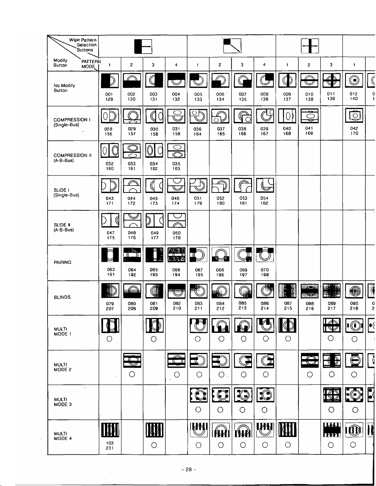
WIPE PATTERN TABLE
Page 28

Page 29

SPECIAL MODE
No, 1 No. 2
No, 3 No. 4
No. 5
NAM
060
055
056
104 185
LUM KEY
061 062
057
CHROMA KEY
058
186
- 30 -
059
—
Page 30

Remarks:
1. Each box number should be read as,
001
129
------
------
► Normal Wipe
► Reverse Wipe
2. The box marked (Q) not be accessed by external controller. However, the wipe pattern can be available.
3. No wipe pattern is available tor the blank box.
- 31 -
Page 31
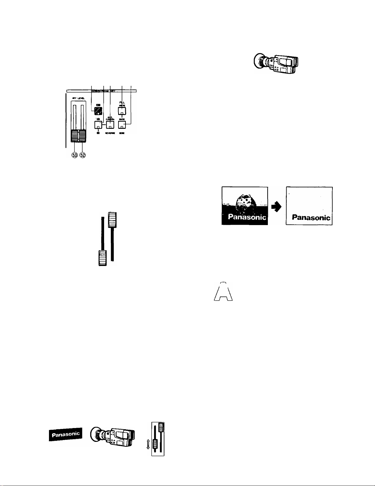
E. Basic Operation*4 Downstream Key
The following instructions detail the Downstream Key
block. This function is mainly used for superimposing
the characters or letters as for a telopper. The optional
Character Generator WJ-KB50 can be used for this
purpose.
□ □ [I]
(ID ® ®
Set the Low Level Key Control (53) to the end low
position and the High Level Key Control (52) to the top
high position
In case the title is written with black letters on the white
card, adjust the High Level Key Control (54) to obtain a clear
edge key image.
Panasonic
Notes
1.
When the optional Character Generator WJ-KB50 is
used for the key source, set both the KEY LEVEL
controls (52) (53) to the low end position.
2.
If the EXT. CAMERA signal is jittery, as in the case of a
VTR playback signal, this could cause a disturbance in
synchronization.
When the REVERSE Button (50) is pressed, the keyedimage and the background image will reverse the
settings.
Normal
Reversed
Turn the Mix/wipe Lever (99) to the B-bus position.
Select and press either the MATTE Button (47) or the
WHITE Button (48) as a Key-Fill signal. The Key-Fill
signal will be filled on the key signal. When the MATTE
Button (47) is pressed, the choice of desired color is
available from the MATTE GENEFtATOR,
Press the EXT. CAMERA Button (46) as a Key Signal,
(or A-Button (45) or B-Button (51) can be selected)
Press the ON Button (44). The Fill color will then be
displayed.
Adjust the Low Level Key Control (53) to obtain the
clear edge key image. Similarly adjust the High Level
Key Control (52) as necessary.
Example of using the title card option.
In case the title is written with white letters on the black
card, adjust the Low Level Key Control (53) to obtain a clear
edge key image.
When the EDGE Button (49) is pressed, two types
(shadow, border) and five kinds of edges are available
by pressing this button repeatedly.
Normal
Narrow Border
Wide Border
'A'
Narrow Shadow Wide Shadow Drop Shadow
Notes :
1. When the Key image is white, the color on the
edge of the threshold can be set to any one of 9
colors, solid or graded by pressing the Matte Color
Selector (13) and the Gradation Button (12) to the
desired color.
2.
When the Matte Colored key image is used, the
edge color if displayed at ail is always black.
- 32 -
Page 32

F. Basic Operation-5
Fade
Synchronized fading makes it possible to operate the
Video, Downstream Key and Audio fades together, or in
any combination. Each of the three can be controlled
independently, via either Auto Fade or a manual Fader. The
following area shows the Fade Control Block.
yfïïMO
□
Ù
B
■On
0~i
'r
g) ® @ ®
Note
If the automatic fading is to be operated, first
adjust the TRANSITION Control (91) to the desired
auto fading time. Then press the AUTO FADE
Button (92) when ready to execute. The Auto-Fade
can be stopped during Auto-fading by pressing this
button. The LED on the VIDEO Button (80) blinks
while stopping. The Auto-fading will start again by
pressing the AUTO FADE Button (92) again.
F-2. Downstream Key Fade-Out (In)
• Set the Fade Control (95) to the IN (OUT) position
• Press the DSK Button (82).
• Slide the Fade Control (95) to.the OUT (IN) position. The
IN (OUT) LED starts blinking (as the fade progresses)
then the OUT (IN) LED begins blinking after the fade is
halfway done. The OUT (IN) LED becomes continuously
on when the Fade Control (95) reaches the OUT (IN)
position.
The VIDEO (80), DSK (82) and/or AUDIO (84) signals can
fade out to one of the following ; MATTE (81), WHITE (83),
BLACK (85), A (93), or B (94) signal.
F-1, Video Fade-Out (In)
• Set the Fade Control (95) to the IN (OUT) position.
• Select the fade out scene from: MATTE, WHITE, BLACK
A or B.
• Press the VIDEO Button (80).
• Slide the Fade Control (95) to the OUT (IN) position. The
IN (OUT) LED starts blinking (as the fade progresses)
then the OUT (IN) LED begins blinking after the fade is
halfway done. The OUT (IN) LED becomes continuously
on when the Fade Control (95) reaches the AUT (IN)
position.
Note
If the automatic fading is to be operated, first
adjust the TRANSITION Control (91 ) to the desired
auto fading time. Then press the AUTO FADE
Button (92)when ready to execute. The Auto-Fade
can be stopped during Auto-fading by pressing
this button. The LEO on the DSK Button (82) blinks
while stopping. The Auto-fading will start again by
pressing the AUTO FADE Button (92) again.
F-3. Audio Fade-Out (In)
• Set the Fade Control (95) to the IN (OUT) position.
• Select the fade out scene from : MATTE, WHITE,
BLACK, A, or B.
• Press the AUDIO Button (84).
• Slide the Fade Control (95) to the OUT (IN) position. The
IN (OUT) LED starts slinking (as the fade progresses)
then the OUT (IN) LED begins blinking after the fade is
halfway done. The OUT (IN) LED becomes continuously
on when the Fade Control (95) reaches the OUT (IN)
position.
- 33 -
Page 33
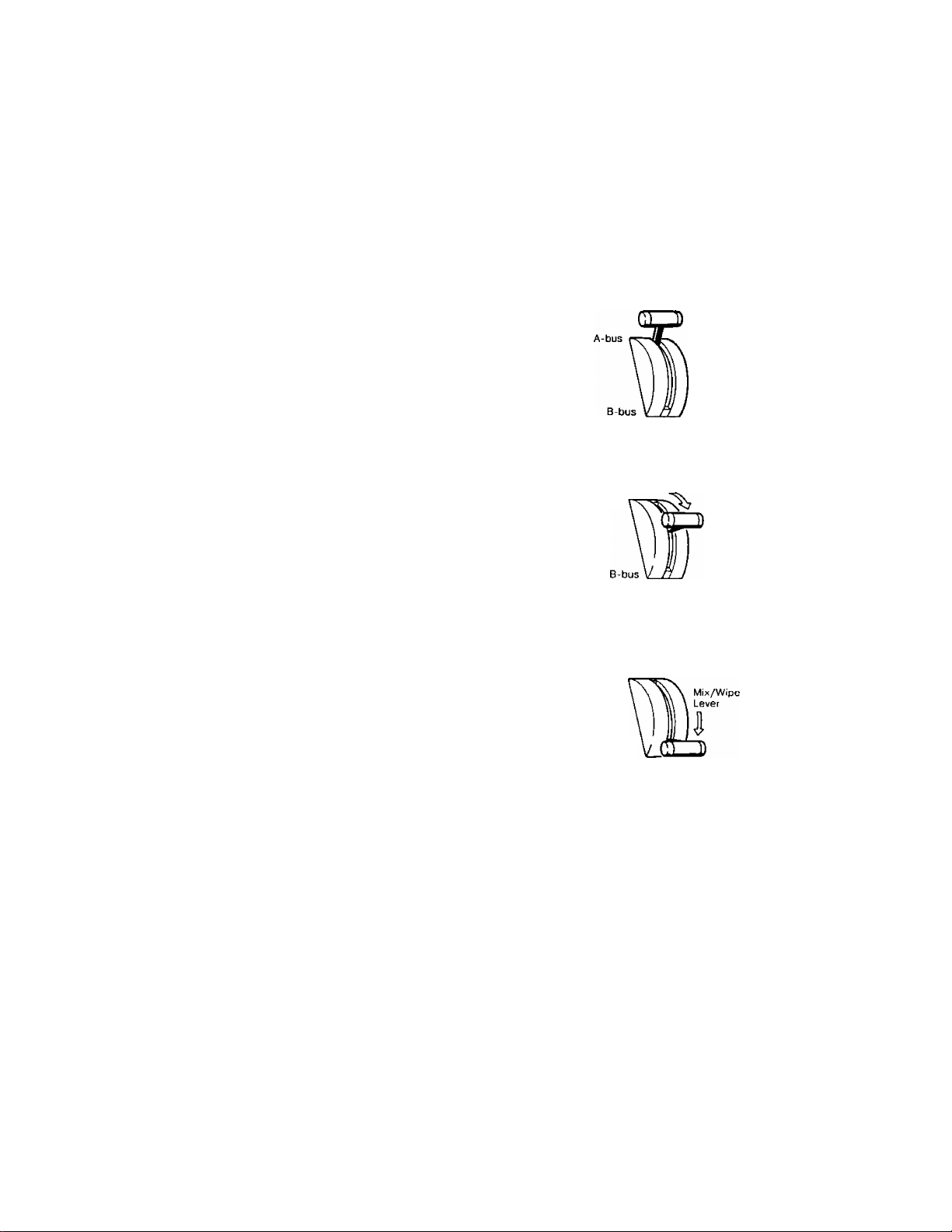
Notes :
1. If the automatic fading is to be operated, first
adjust the TRANSITION Control {91) to the desired
auto fading time. Then press the AUTO FADE
Button (92) when ready to execute. The Auto-Fade
can be stopped during Auto-fading by pressing this
button. The LED on the AUDIO Button (84) blinks
while stopping. The Auto-fading will start again by
pressing the AUTO R^DE Button (92) again,
2. The headphone audio does not fade.
3. When either MATTE, WHITE or BLACK is selected
for the fade out scene, no sound comes out.
However when-either A or B is selected for the
fade out scene, A-bus audios, Aux-1 and Aux-2
audios or B-bus audios, Aux-1 and Aux-2 audios
will be outputted.
Remarks :
1. Any combination of VIDEO, DSK and/or AUDIO can be
selected for fading. The LED in each button indicates
which of the three are currently selected. If none are
selected the Fade Control Area is effectively disabled.
2. The video signal can be Faded-out to,
- MATTE (81)~The selected MATTE Color.
- WHITE (83)-A White background.
- BLACK (85)-A Black background.
- A-Bus (93)-Uneffected A video signal.
- B-Bus (94)-Uneffected B video signal.
3. A partial Fade which is either interrupted (by
re-pressing Auto Fade (92) while Fade is in progress)
or by releasing the Fade Control (95) before completion
will display a mixed image of the selected signals,
4. Only the outputs selected for fading are processed.
Example-1 ;
If VIDEO is chosen but not DSK (while the
Downstream Key Function is activated) then only
the VIDEO portion of the final image will Fade the Downstream Key image will remain on screen,
un-faded.
G. Basic operation-6
Audio Follow
Audio can be processed either separately or in conjunction
with video source selection.
The Audio Follow provides automatic audio ratio mixing
(between A-bus and B-bus inputs) via the Mix/Wipe Lever
(99), according to the ratio of A and B inputs as effected.
• Press the AUDIO FOLLOW Button (79)
• Adjust the Mix/Wipe Lever (99) to the A-bus or B-bus
position.
• The audio level ratio between the A-bus and B-bus
changesjaccording to the position of the Mix/Wipe
Lever (99).
A B
Audio
Output
Mix/Wipe
A-bus
A-bus
Lever
A B
Audio
Output
Example-2 ;
If both VIDEO and AUDIO are selected
(Downstream Key not activated, so not eligible for
fading) and fade-out to B-bus is also selected,
then the combined video-audio (at Fade In
position) with all effects will fade to the uneffected
B-Bus video and audio.
(i.e. any A-Bus inputs and effects will fade-out,
leaving only B. If AUX 1 and/or MIC/AUX 2 Audio
are present, they also will remain.)
B-bus
A B
Audio
Output
Note
If AUXt and/or MIC/AUX2 inputs are used they
are controlled directly via their respective faders
(87), (88) - i.e. they will be uneffected by the Audio
Follow function.
- 34 -
Page 34

H. Application
H-l. Event Memory Functions
Customized effect combinations can be stored in
the Event Memory, and later recalled for subsequent
access. The MEMORY Button (19) and SHIFT Button
(18) are used to store the desired effects.
To clean/reset the eight memories.
Press Power ON/OFF Button (1) to turnoff. Then, while
holding down both MEMORY Button (19) and SHIFT
Button (18) press Power ON/OFF Button (1) to turn on
again.
~pgeH~i
Q
To set a Memory location,
Choose desired effects on panel. When the correct
combination is selected press MEMORY Button (19)
then press the appropriate EVENT NO, Button (14). (for
location 5-8, press SHIFT Button (18)). The LED on the
EVENT NO. Button (14) blinks 3 times then goes off
when memory is completed.
□
M^moris^ aux
$
posilions no.
ou no 5
• To recall an event setting, press (for 5-8 : press SHIFT
Button (18), then) the correct EVENT NO. Button (14)
then press the AUTO TAKE Button (97).
Note :
Up to eight pre-set Event combinations are
available, if executing Auto Take successively,
each memory occurance will be performed in
sequence according to the numerical locations
used, i.e. only stored numbers will be "toggled"
through. So if #3 was skipped in the event memory
setting, it will also be skipped by pressing AUTO
TAKE Button (97),
Caution :
The event memory will disappear in a few days
leaving the Main Power Switch (131) off.
H-2. Special Mode Functions
Under "Special Mode" eight factory preset effect
functions are accessible for use. These demonstrate a
few of the many capabilities of the instrument.
Note :
Before operating the Mode 6-Shutter, Mode
7-Vibrate or Mode 8-Satellite, be sure to turn the
Mix/Wipe Lever (99) to the B-bus position.
Simultaneously press the MEMORY Button (19) and
SHIFT Button (1 8). The MEMORY Button (1 9) LED will
begin blinking indicating that the instrument is in Special
Mode.
Each mode is accessed (when MEMORY Button (19)
LED is blinking) by pressing (for 5-8, press SHIFT Button
(18)) the appropriate EVENT NO. Button (14).
(1) Mode 1 - Mosaic Mix :
Press No.l button. The mix pattern from A-bus
and B-bus becomes a mosaic during the mix.
This can be executed by the Mix/Wipe Lever
(99) or by Auto Take Button (97) or by external
controller equipped with GPI (or RS422).
(2) Mode 2 - Stream :
Press No.2 button. The compressed image
zooms in from corner. Two corners are
available by the Positioner Joystick (2). This
can be executed by the Mix/Wipe Lever (99)
or by Auto Take Button (97) or by external
controller equipped with GPI (or RS422).
(3) Mode 3 - Cork Screw :
Press No.3 button. The compressed image
corkscrews in from corner. This can be
executed by the Mix/Wipe Lever (99) or by
Auto Take Button (97) or by external controller
equipped with GPI (or RS422).
(4) Mode 4 - Bounce :
Press No.4 button. The compressed image
drops-bounce in from corner, This can be
executed by the Mix/Wipe Lever (99) or by
Auto Take Button (97) or by external controller
equipped with GPI (or RS422).
(5) Mode 5 - Flip :
Press No.5 button. The Vertical Split
Compressed Wipe is obtained on the Matte
Color. This can be executed by the Mix/Wipe
Lever (99) or by Auto Take Button (97) or
by external controller equipped with GPI (or
RS422).
(6) Mode 6 - Shutter;
Press No.6 button. The Horizontal Split Wipe
from B-bus to Matter Color is obtained. This
can be executed using either the Auto Take
Button (97) or by externa! controller equipped
with GPI,
- 35 -
Page 35

Note :
When the Square Wipe Button (60) is selected
at this moment, the Mode 6 changes to the
Circle Wipe mode.
(7) Mode 7 - Vibrate ;
Press No.7 button. The Horizontal Shake of
B-bus is obtained.
This can be executed using either the Auto
Take Button (97) or by external controller
equipped with GPI,
Note :
The vibration lasts for 64 video frames.
(8) Mode 8 - Satellite :
Press No.8 button. The compressed satellite
moving of B-bus image can be obtained.
B-bus image orbits within A-bus image.
This can be executed using either the Auto
Take Button (97) or by external controller
equipped with GPI.
Notes :
1. The satellite moving starts and stops using
either the AUTO TAKE Button (97) or by
external controller equipped with GPI.
2. This mode will not be released unless other
mode or function is selected.
To cease special mode, press the MEMORY Button (19)
and SHIFT Button (18) simultaneously again. The unit
returns to the status as it was.
H-3. Auto Take
Instead of the lever controlled Mix and Wipe using
the Mix/Wipe Lever (99), an automatic Mix and Wipe
operation can be made using Auto Take function. Two
kinds of Aufo Take are available.
1. Standard Auto Take
• Set up the Wipe Pattern and the Digital Effect as
desired.
• Select the Mix Effect function from NAM Button (72),
MIX Button (73), WIPE Button (74), LUM KEY Button (75)
and CHROMA KEY Button (76),
• Adjust the TRANSITION Control (98) to the desired auto
take time,
• Press the AUTO TAKE Button (97),
The Auto-Take can be stopped during Auto-taking by
pressing the AUTO TAKE Button (97). The LED's on
both A-bus and B-bus buttons blink while stopping.
The Auto-taking wilt start again by pressing the AUTO
TAKE Button (97) again,
2. Memory Auto Take
• Select and recall the programmed memory by pressing
the EVENT NO. Button (14).
• Press the AUTO TAKE Button (97), The memorized
program will be performed. After this, the next Event
Number is selected automatically.
• Press the AUTO TAKE Button (97) again. The another
program will be performed.
The memorized program can be recalled and performed
one after another by pressing the AUTO TAKE Button
(97) repeatedly.
The Auto-Take can be stopped during Auto-taking by
pressing the AUTO TAKE Button (97). This button blinks
while stopping. The Auto-taking will start again by
pressing the AUTO TAKE Button (97) again.
H-4. Digital Effects
Many unique Digital Effects are available through this
Digital AV Mixer. By combining specific digital attributes
the experienced user can generates a host of tailored
processes for specific applications. And each can be
stored in a memory location (Event Memory) for instant
recall. Below are a couple of sample combinations.
Auto-Take
1.
Select the same source input for both the A-bus and
B-bus then adjust 2 different Digital Effect versions
which can then be mixed or wiped over each other as
desired. For example
..........
,
Reset the functions to the factory set up mode by
turning off and on the power of the unit.
Press and activate the PAINT Button (36) and STROBE
Button (38) for the A-bus version. The Mix/Wipe Lever
(99) should be turned to A-bus position at this moment.
Turn the Mix/Wipe Lever (99) to the B-bus position.
Press the B-Button (57) on the DIGITAL EFFECT block.
Press the NEGA Button (31).
Adjust the the TRANSITION Control (98) down to "MIN"
position.
Then press the AUTO TAKE Button (97) repeatedly. The
2 different Digital Effect versions instantly overlays the
other set of digital effects for the effected same source
input, as desired.
B-bus
Negative
2.
Mosaic-Spotlight
A-bus
Paint + Strobe
Reset the functions to the factory setup mode by
turning off and on the power of the unit.
Select the same source input for both the A-bus and
B-bus.
The A-bus should have no Digital Effects applied to it.
Turn the Mix/Wipe Lever (99) to the B-bus position.
Press the B-Button (57) on the DIGITAL EFFECT block.
Press the MOSAIC Button (33).
Press the Square Button (60) on the WIPE PATTERN
block.
Adjust the Mix/Wipe Lever (99) to obtain the desired
wipe size.
Press the Positioner ON/OFF Button (3).
- 36 -
Page 36

The Positioner Joystick (2) now controls the location of
the mosaic image.
If the border is desired to highlight the "anonymous"
area, press the BORDER Button (25} on the WIPE
PATTERN block.
If the Reverse function (REVERSE Button (28)) and/or
the Monochrome function (MONO Button (34)) is added,
more highlight effect can be produced.
A-bus
B-bus
+
3.
After Image
Reset the functions to the factory setup mode by
turning off and on the power of the unit.
Select the same source input for both the A-bus and
B-bus.
Press the STROBE Button (38).
Press the MIX Button (73).
Adjust the TIME Control (39) and Mix/Wipe Lever (99)
to obtain the necessary After Image.
If required, press the A/V SYNCHRO Button (43) to
synchronize this effect to the audio.
5.
Picture-in-Picture
«
Reset the functions to the factory setup mode by
turning off and on the power of the unit.
Press the Square Wipe Button (60).
Press the COMPRESSION Button (71).
Press the Positioner ON/OFF Button (3).
Adjust the size of the square wipe picture by using the
Mix/Wipe Lever (99).
Press the SCENE GFIABBER Button (4).
The other wipe patterns can be selected by pressing
the Square Wipe Button (60) repeatedly .... circle, oval,
and diamond. Then adjust the Mix/Wipe Lever (99) to
obtain the smaller wiped size.
Note :
Only square wipe pattern in the Picture-in-Picture
mode can be stored to the Event Memory.
4.
Multi/Live pictures mixing
Reset the functions to the factory setup mode by
turning off and on the power of the unit.
Select the same source input for both A-bus and B-bus.
Press the MULTI Button (40).
Press the COMPRESSION Button (71) and Square Wipe
Button (60).
Adjust the Mix/Wipe Lever (99) to change the size of
square picture.
Press the STROBE Button (38). The live picture in
the center of the monitor screen and the multiple still
pictures on the back is obtained.
If required, change the position of the live picture by
operating the Positioner Joystick (2).
H-5. Event Memory accessed by AG-A800
The Event Memory can be accessed by AG-A800 at the
points of DSK IN/OUT set by AG-A800.
Note :
1. Do not execute the Wipe or Mix effects with
transition time under the Event Memory in AB-Roll
Editing.
2. This application can be applied for the NEGA,
MONO, MOSAIC, PAINT, TRAIL and MULTI on the
A-bus in DIGITAL EFFECT block, and also be
applied for on/off of the Color Correction. In this
case, the Assemble Editing should be used instead
of AB-Rolt Editing.
(Example)
• Memorize the MOSAIC on A-bus into Event
Memory No. 1.
• Select A-bus picture.
* Stand by the editing system and select the Event
Memory No. 1.
♦ Execute the editing. At the point of IN of DSK Key,
the Event Memory No. 1 will be started.
Then at the point of OUT of DSK Key, the Event
Memory No. 1 will be finished.
-37 -
Page 37
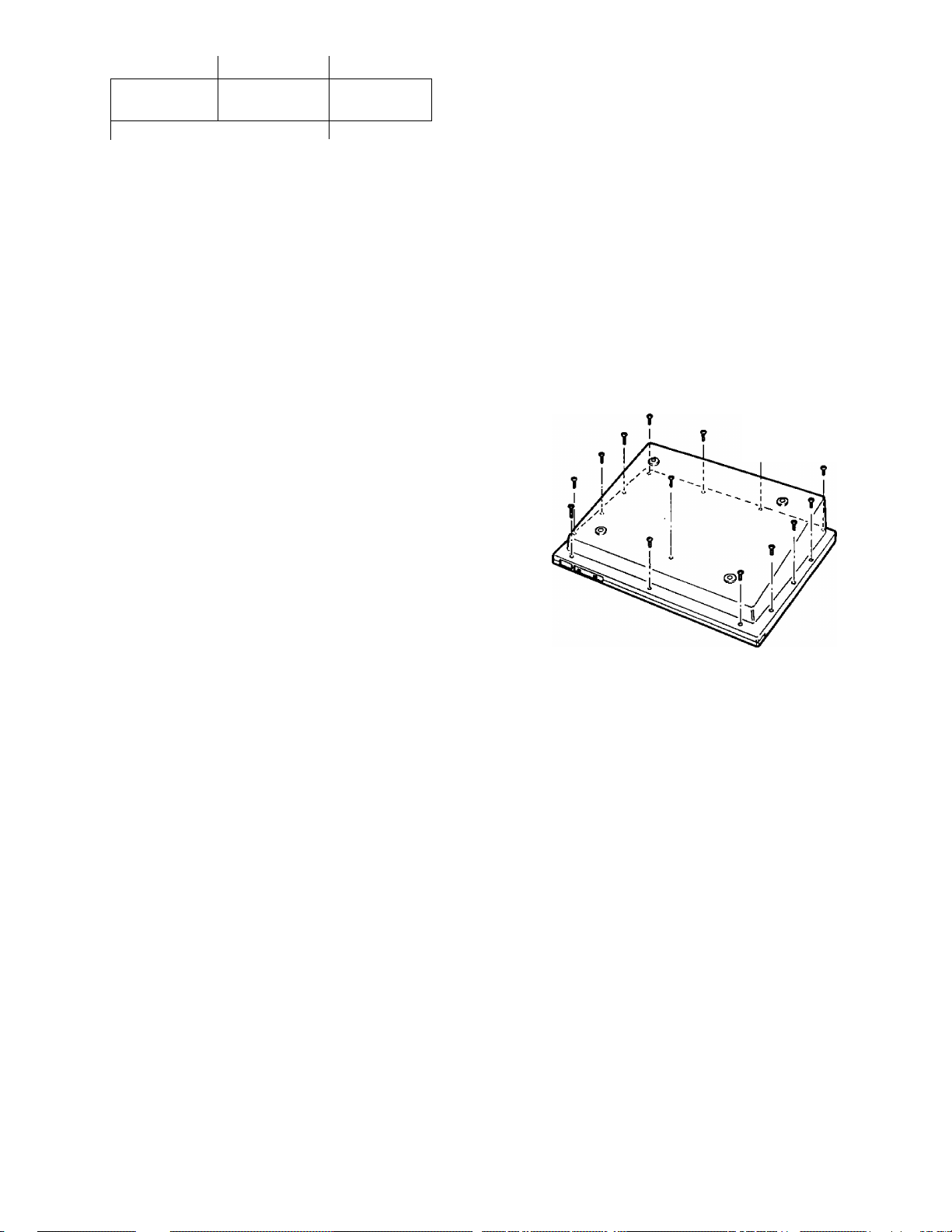
□SK IN
DSK OUT
INTERFACE
No. 1
Stand-by
A .
Event Memory
No. 1
Finish
A
Notes :
1. When accessing the regular DSK function from
AG-A800, turn off all the Event Number Button
(14). The DSK function and the Event Memory can
not be used at the same time.
2. The setting up of the transition time of KEY IN/OUT
by AG-A800 should be "0". If not, the OUT point of
DSK changes.
3. The transition time of the Event Memory should
be shorter than the period between DSK IN and
DSK OUT. Otherwise, the Event Memory will not
be finished at the DSK OUT position.
The WJ-MX50 is equipped with the interface capability for
use with an external remote controller such as the AG-A800
(Editing Controller), a personal computer or a GPI function
product. Refer to the service personnel or system installer
for setting up of interface.
1. GPI (General Purpose Interface)
The WJ-MX50 accepts a GPI signal from an external
remote controller. The GPI signal can be used to
activate the Auto Take function of the WJ-MX50.
Setting up the switch.
(This switch has been set at right position (OFF) at
factory. The setting up may not necessary locally.)
• lurn off unit and disconnect power supply.
• When handling unit take care not to damage the many
controls, faders, joysticks and switches.
• Open the top panel by.removing the 14 case screws.
Remove screws.
Î
• There are 2 square holes on the shield plate as shown.
Turn the switch number 1 on SW702 to the OFF position
if this switch has been set to the ON position.
SW702
• Close the top panel by fixing the 14 case screws.
• Supply the GPI signal to the GPI Input Connector (129)
on the rear panel.
Pulse Timing
• The Auto Take function is activated at the point of the
falling edge of the GPI pulse, as shown.
H
\ t
n
-38 -
Page 38
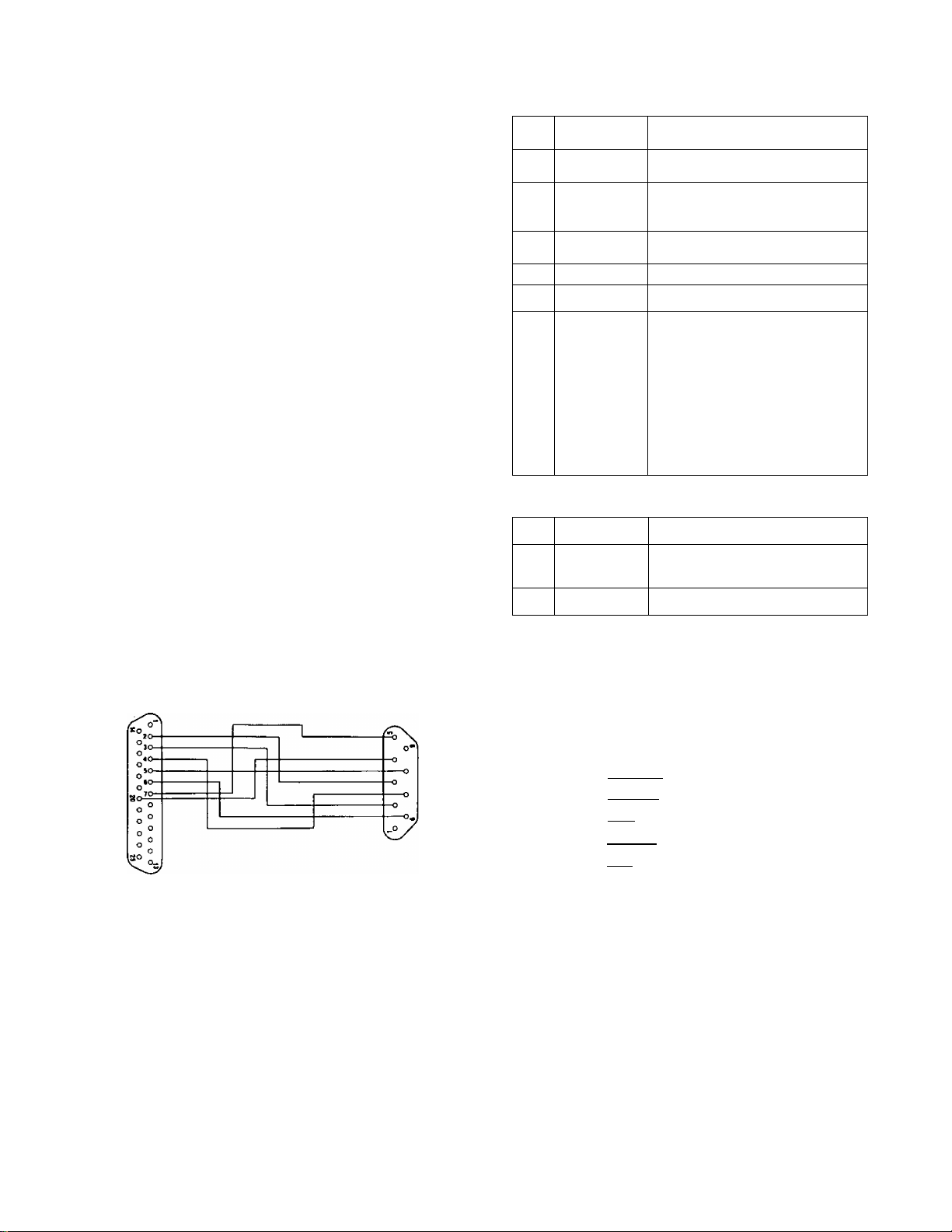
2. RS422
The optional Editing Controller AG-A0OO can be used
with the WJ-MX50 to control it remotely in the VTR
Editing System.
Setting up
• Turn the J^S422/RS232C Selection Switch (133)
on the rear panel to the RS422 position.
• Connect the control cable between the AG-A800
and the Editing Controller Connector (132) on the
WJ-MX50.
• The pin configuration of the Editing Controller
Connector (132) is as follows.
1. Ground
2. Transmit A
4. Receive Common
5. Spare
6. Transmit Common
7. Transmit B
8. Receive A
9. Ground'
3.
RS232C
2, Refer to the table below for transmitting protocol
between the RS232C DT/WJ-MX50 connection.
SW701
No. Switch Name Description
1. Bit length
2. Stop bit ON - 2 bits
3. Parity ON - OFF, OFF-ON
4. Even/Odd ON (Odd) Of OFF (Even)
_
5.
6, 7, 8 BAUD rate
ON - 8 bits
OFF - 7 bits
OFF - 1 bit
OFF
No. 6 No. 7 No. 8
OFF OFF OFF —> 19.2 kbps
ON OFF OFF —r 9.6 kbps
OFF ON OFF —> 4.8 kbps
ON ON OFF —> 2.4 kbps
OFF OFF ON —> Inhibited
ON OFF ON ^ Inhibited
OFF ON ON —> Inhibited
ON ON ON —> Inhibited
can be used with the WJ-MX50 for remote operation.
Setting up the switch
• Open the top panel by removing the 14 case
screws.
• Set the switch {SW701) referring to the Note-2
and 3 below.
• Close the top panel by fixing 14 case screws after
setting the switch correctly.
Notes :
1. Make the required conversion cable referring to
the following wiring information.
RS232C
25-pin
2 TXD
3 RXD
4 RTS 7
5 CTS
6 DSR 6
7 SIG. G
20 DTR
WJ-
■MX50
9-piri
3 TXD
2
. RXD
RTS
8 CTS
DSR
5 SIG. G
4 DTR
[DCE Connection]
SW702
No. Switch Name Description
1. RS422 Parity ON - Odd
OFF - Even (Factory Setup)
2 - 8
-
Ail OFF
3. The switch (SW701) has been set as follows at
factory. Change this basic setting up to meet
necessary Modem requirements.
SW701
ON OFF
[~TTTT1
r~rTTT1
rnrrn
r~nm
nm I
nnsn
SW702
ON OFF
SW-8
SW-7
SW-5
SW-5
SW-4
SW-3
SW-2 ] STOP BIT
SW-1 ] BIT LENGTH
BAUD RATE
sw-e
czu
d[
cin
SW-7
SW-6
SW-5
SW-4
SW-3
SW-2
SW-1 RS422 Parity
- 39 -
[Factory Setup Mode]
Page 39

SPECIFICATIONS
Source Input :
Composite Video Input;
S-Video Input :
Audio Input:
Auxiiliary Audio Input:
Microphone Input :
External Camera Input:
GPi Input;
Character (TITLE) Input:
Program Output;
Composite Video Output
S-Video Output:
Audio Output:
Previw Output:
Black Burst Output;
Advance Sync Output:
Advance Reference Output:
Headphone Output;
Digital Effects;
Matte Colors :
Wipe Patterns :
Joystick Control :
Audio Mixer:
Others ;
Video Sampling :
Frequency Range :
Frequency Responce :
Gain :
S/N (Typical) :
Differential Gain :
Differential Phase :
Power Source :
Power Consumption :
Ambient Operating Temperature
Ambient Operating Humidity :
Dimensions :
Wight ;
X4 (SOURCE 1/2/3/4)
1.0 Vp-p/75 Ohms, NTSC signal, BNC x4
Y signal; 1.0 Vp-p/75 Ohms, C signal; 0.286 Vp-p/75 Ohms,
Mini DIN .4 connectorX4
SOURCE 1 /2; XLR-typex2, +4 dBm/600 ohms (Balanced), Left and Right.
SOURCE 3/4; Pin-jackx2, —6 dBs/20 Kohms (Unbalanced), Left'and Right.
X2 (Aux1/2)
—6dBs/20 Kohms, Pin-jack (Unbalanced), Left and Right
— 60 dBv/600 ohms, unbalanced, tip-ring-sleeve type phone jackx 1
1.0 Vp-p/75 ohms, NTSC compostie signal, BNCx 1
Y signal; 1.0 Vp-p/75 ohms, C sign'al;.0,286 Vprp/75 ohms.
Mini DIN 4 connectorXt
Make-contact, BNCx 1
10-pin connectorxl for optional Character Generator WV-KB12A, WJ-KB15,
WJ-KB50.
X2 (PROGRAM OUT 1/2)
1.0 Vp-p/75 ohms NTSC signal, BNCx2
Y signal; 1.0 Vp-p/75 ohms, C signal; 0.286 Vp-p/75 ohms.
Mini DIN 4 connectorx2
PROGRAM OUT 1; XLR-typeX1, +4dBs/47 ohms (Balanced), Left and Right.
■ PROGRAM OUT 2; Pin-jackx 1, —6dBs/47 ohms (Unbalanced), Left and Right,
1.0 Vp-p/75 ohms, NTSC composite signal, BNCx 1.
Sync 0.286 Vp-p/75 ohms. Burst 0.286 Vp-p/75 ohms NTSC signal, BNCx 1.
4 Vp-p/75 ohms, BNCx2
Sync 0.286 Vp-p/75 ohms. Burst 0.286 Vp-p/75 ohms, BNCx2
—20 dBv —80 dBv, 8 ohms unbalanced, tip-ring-sleeve type phone jackx 1.
Nega, Mosaic, Mono, Paint, Still, Strobe, Multi, Trail, A/V Synchro, Frame
Color Bar, White, Yellow, Cyan, Green, Magenta, Red, Blue, Black.
287 Patterns
Positioner, Color Correction,
A-bus, B-bus, AUX-1, AUX-2, Mic, Master.
Audio-Follow, Auto-Take, Auto-Fade, Memory, Special Mode,
4 : 1 ; 1, Y = 14.3 MHz (936 fH), 8-bit component
Sync; 15,734 KHz±300 Hz
SC; 3.579545 MHz±40 Hz
Y/C signal; 4,5 MHz (at—3dB)
Composite Video Signal; 4,5 MHz (at —3dB)
Audio; 20 - 20 KHz (at -3 dB)
Unity (Video)
56 dB (S-Video), 50 dB (Composite), 70dB (Audio at 1 KHz)
±5° (Composite)
±5 % (Composite)
120VAC60HZ
Operation mode; Approximately 45W
Stand-by mode; Approximately 5W
32- 104°F(0-40°C)
Less than 90/.
18-7/8" (W) X 6-7/16" (H)x 14-1/2”(D)
[480 (W)X164 (H)X396(D) mm]
1 5 lbs. (6.8 Kg)
Weight and dimensions indicated above are approximate.
Specifications are subject to change without notice.
STANDARD ACCESSORY i /¿5^^
Wipe Pattern Sheet
.........................
/...................................................... 1 pc.
OPTIONAL ACCESSORIES
• Charactor Generator
..................................
WV-KB12A, WJ-KB1 5, WJ-KB50
-40
l-M
I ,
fX6
li
Page 40

Panasonic
Communications & Systems Company
Division of Matsushita Electric Corporation of America
PROFESSIONALVINDUSTRIAL VIDEO
HEADQUARTERS:
50 Meadowland Parkway, Sacaucus, Naw Jersay 07094
EASTERN ZONE:
50 Meadowland'Parkway. Secaucua. NJ 07094(201)348-7620
CENTRAL ZONE:
425 E. Algorxiuin Road. Arlington Hts. IL 60005 (7081981-4826
SOUTHERN ZONE:
Dallas Région: 4500 Amon Carter BIvd .Fl Worth. TX 76155(817) 685-1117
Atlanta Region: 1854 Shackleford Ct. Suite 115 Norcross. GA 30093 (404) 925-6841
WESTERN ZONE:
Seattle Région: 1200 Westlake Ave. N.. Suite 508. Seattle. WA 98109(206) 285-8883
Los Angeles Région: 6650 Katella Ave., Cypress. CA 90630 (714) 373-7275
MATSUSHITA ELECTRIC OF CANADA UMITED
5770 Ambler Drive, Mississauga. Ontario. Canada L4W 2T3 (416) 624-5010
PANASONIC SALES COMPANY
DIVISION OF MATSUSHITA ELECTRIC OF PUERTO RICO, INC.
San Gabriel Industrial Park, 65th Infantry, Ave. KM. 9.5 Carolina, Puerto Rico 00630 (809) 750-4300
N0592-0 YWV0QA2763BN Printed in Japan
(N) 15
 Loading...