

Page 1
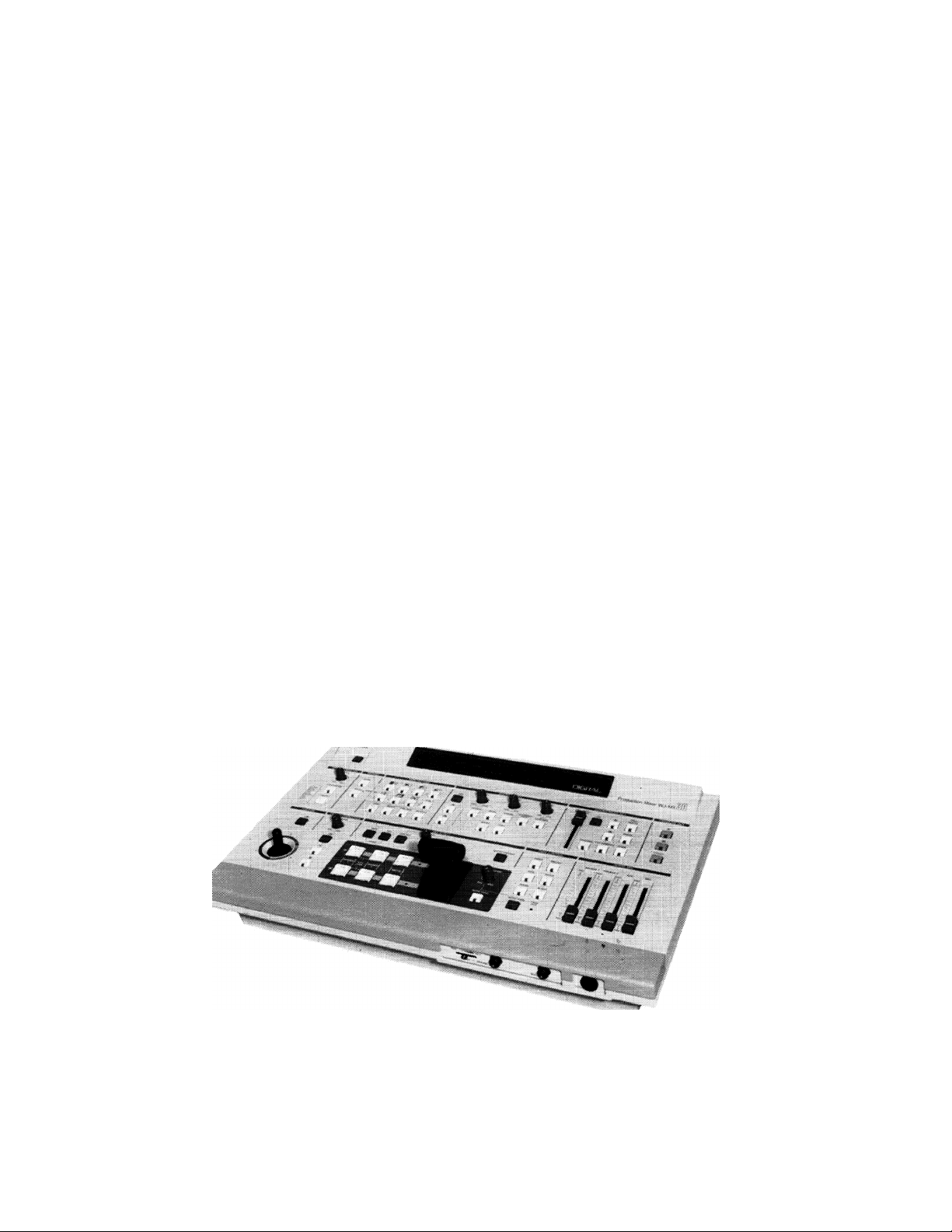
Operating
Instructions
Digital AV Mixer
WJ-MX30
Panasonic«
Before attempting to connect or operate this product, please read these instructions completely.
Page 2
CAUTION:
Before attempting to connect or operate this product,
please read the label on the bottom.
CAUTION
RISK OF ELECTRIC SHOCK
DO NOT OPEN I / •
CAUTION:
TO REDUCE THE RISK OF ELECTRIC SHOCK, DO
NOT REMOVE COVER (OR BACK). NO USER SER
VICEABLE PARTS INSIDE.
REFER SERVICING TO QUALIFIED SERVICE
PERSONNEL.
The lightning flash with arrowhead
symbol, within an equilateral triangle,
is intended to alert the user to the
presence of uninsulated "dangerous
voltage" within the product's
enclosure that may be of sufficient
SA 1965
magnitude to constitute a risk of elec
tric shock to persons.
The exclamation point within an
equilateral triangle Is intended to alert
the user to the presence of important
operating and maintenance (servicing)
instructions in the literature accompa
nying the appliance.
SA 1966
.....................................................................................................For U S A .
Warning:
This equipment generates and uses radio frequency
energy and If not installed and used properly, i.e., in
strict accordance with the instruction manual, may
cause harmful interference to radio communications.
It has been tested and found to comply with the limits
for a Class A computing device pursuant to Subpart
J of Part 1 5 of FCC Rules, which are designed to pro
vide reasonable protection against such interference
when operated in a commercial environment.
.............................................................................................. For CANADA .
This digital apparatus does not exceed the Class A
limits for radio noise emissions from digital apparatus
set out In the Radio Interference Regulations of the
Canadian Department of Communications.
The serial number of this product may be found on
the bottom of the unit.
You should note the serial number of this unit in the
space provided and retain this book as a permanent
record of your purchase to aid identification in the
event of theft.
Model No. __________________________________
Serial No.
__________________________________
WARNING:
TO PREVENT FIRE OR SHOCK HAZARD, DO NOT EXPOSE THIS APPLIANCE TO RAIN OR MOISTURE.
Page 3

PREFACE ....................................
MAIN FEATURES ........................
PRECAUTIONS ...........................
MAJOR OPERATING CONTROLS
A.
A-1. Power A-2. Reset •
B.
B-1.
B-2.
B-3.
B-4.
B-5.
C.
D.
D-1. Mix .
D-2. Wipe
Audio Mixer
1. W
Factory Preset Operation mode
CONTENTS
1
1
2
3
12
13
13
13
13
14
14
14 G.
15
15
16
16
18
18
18
18
2. Wipe Edge
3. Wipe Direction .................................
D-3. Luminance Key
D-4. Pattern Table .........................................
D-5. Picture-in-Picture
Basic Operation 4
E.
E-1. Downstream Key ...................................
E-2. External Key ..........................................
Basic Operation 5 ..........................................
F.
F-1. Video Fade-Out (In) ...............................
F-2. Down stream Key Fade-Out (In)
F-3. Audio Key Fade-Out (In)
Basic Operation 6
H. Applications ...................................................
Fl-1. Event Memory Functions
FI-2. Auto Take
FI-3. Digital Effects
INTERFACE
SPECIFICATIONS .............................................
OPTIONAL ACCESSORIES ..............................
......................................................
......................................
.....................................
..................................
.........................................
...........
.......................
.........................................
......................
.............................................
.......................................
...........
...........
...........
...........
...........
...........
...........
...........
...........
...........
...........
...........
...........
...........
...........
...........
...........
...........
...........
...........
18
19
19
20
22
22
22
23
24
24
24
25
25
26
26
26
26
28
29
29
PREFACE
The Panasonic Digital AV Mixer WJ-MX30 is designed for
use in producing special-effect images by utilizing the
built-in Frame Synchronizer and other digital processing
circuits. In addition to the Mix Effect of .the conventional
Digital AV Mixer, the WJ-MX30 offers such features as
Luminance Key function, Digital Effect, Downstream Key
Effect, Wipe Effect, Fade Control, Memory and many more.
MAIN FEATURES
Built-in Frame Synchronizers for A-bus and B-bus.
Three audio/video source inputs.
Digital Effects such as Nega, Mosaic, Mono, Paint, Still,
Strobe, Scramble and AV Synchro.
Several combinations of the Luminance Key, Mix,
and/or Wipe.
107 Wipe-pattern combinations are available.
9 standard background matte-colors are available from
the Matte Generator.
Audio fade, DSK fade and/or video fade are available
either independently or in combination.
The interval time for Auto-Fade and Auto-Take can be
adjusted independently.
This operating manual is intended to explain the Generator’s
many operational features. With the WJ-MX30 and your
imagination there are many possible function combinations
which are left to your creativity.
9. The audio level can also be linked with the movement
of the Wipe lever.
10. Up to 8 events can be stored in the memory.
11. Advance Sync signal output connectors for use with
VTR editing systems.
12. External key function is provide.
13. Reset function for returning to the preset condition at
the factory.
14. The modes selected by buttons will be kept by memory
back up approximately 1 week even if AC power is
disconnected.
1 -
Page 4
PRECAUTIONS
The WJ-MX30 is a sensitive, high quality instrument and should be treated with care. Because it is an electrical device, the danger
of electric shock exists if it is used inappropriately.
DON'T
Do not attempt to disassemble the instrument. In order
to prevent electric shock, do not remove screws or
covers. There are no user-serviceable parts inside.
X Do not abuse the instrument. Avoid striking, shaking,
etc. It could be damaged by improper handling or
storage.
X Do not use strong or abrasive detergents when
cleaning the instrument body.
X Do not expose the instrument to water or moisture, and
do not operate it in wet or humid areas.
X Do not use the instrument in an extreme environment on
extremely high temperature or high humidity.
IMPORTANT POINTS FOR VIDEO INPUT SIGNAL
DO'S
Do refer all servicing to qualified service personnel.
• Do handle the instrument with care.
Do use a dry cloth to clean the Instrument when dirty.
In case the dirt is hard to remove, use mild detergent
and wipe gently.
Do take immediate action if the instrument becomes
wet. Turn power off and refer servicing to qualified
service personnel. Moisture can damage the
instrument and also create a danger of electric shock.
• Use the instrument under ambient conditions of 0°C to
40°C in temperature, and below 90"/o in humidity.
(1) Failure of input video signals to meet the NTSC color
standard can cause a disturbance of synchronization.
(The picture may jitter or tear)
(2) A very low input signal to noise ratio (S/N) may result in
a low quality picture.
(3) A very jittery source input video signal, for example, a
poor VTR playback signal can cause a disturbance in
synchronization or color.
(4) Tracking noise on the TV monitor can cause a
disturbance in synchronization. It is necessary to adjust
the tracking control of the input VTR.
(5) When either a character generator signal or character
input from a key camera is supplied, the edge of the
characters might become rough as shown below under
certain electronic conditions.
Flag waving (top of picture curls) may appear when a
(6)
certain VTR is used to supply input signal, (due to AFC
time constant)
When an external key video signal is supplied to
(7)
the EXT. CAMERA IN connector, it will be used as
a reference sync signal for the WJ-MX30. A jittery
VTR playback signal, if used as such, can cause a
disturbance in synchronization.
-2-
Page 5
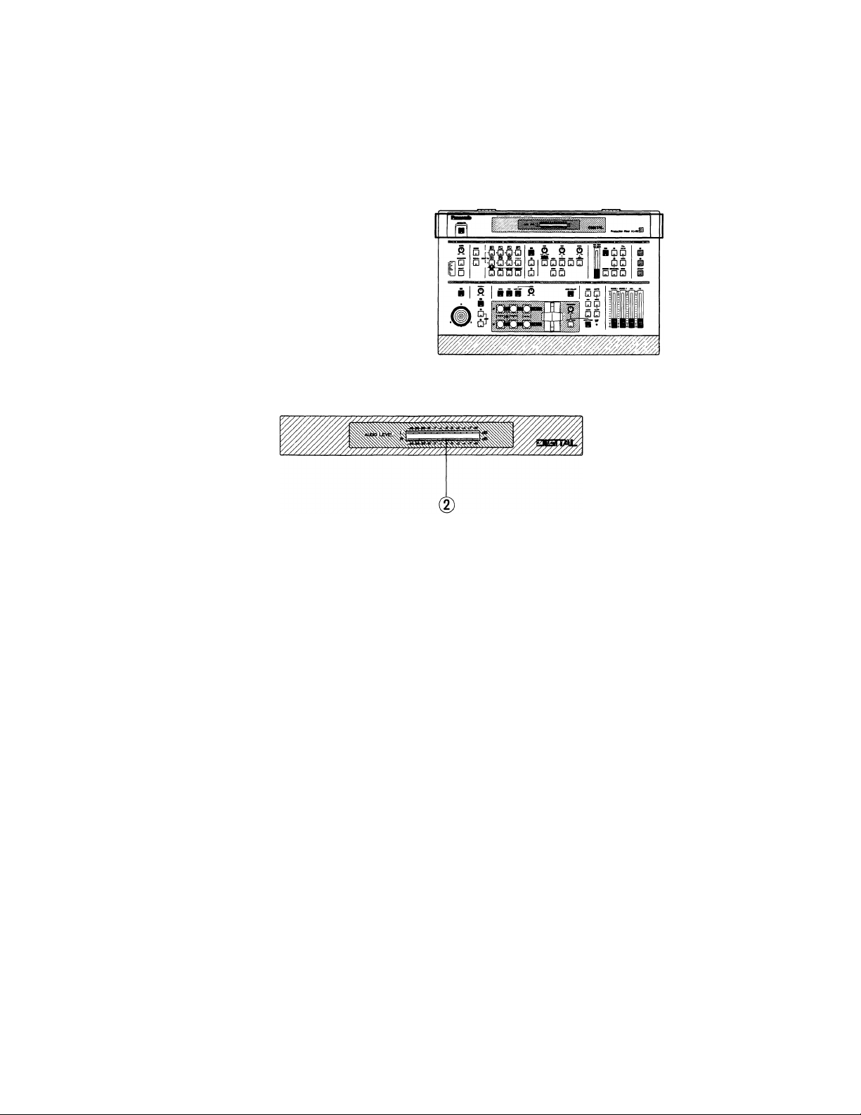
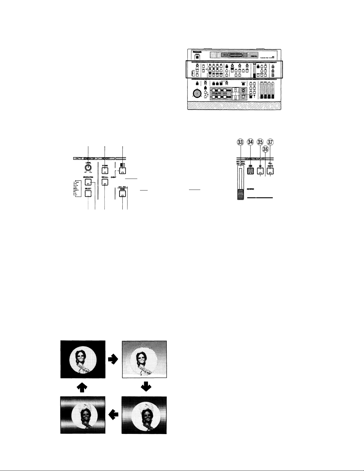
MAJOR OPERATING CONTROLS AND THEIR FUNCTIONS
■ TOP VIEW 1
d)
1. Power On/Off Button (POWER)
Press this button to switch this unit on.
The LED on this button lights and the following LEDs
light up at the same, Effect On/Off Button (20),
Effect-out Button (44), One-way Button (18), Straight
Wipe Button (8), Effect-A Button (21), DSK-A Button
(35), Fill Matte Button (37), Wipe Select Button (51),
Source 1 on A-bus Button (55), Source 2 on B-bus
Button (56), Audio Follow On/Off Button (59) and Black
Fade Button (68).
Note:
The Main Power Switch (98) (located on the back)
must be turned on before this switch is pressed.
Digital AV Mixer WJ-MXI
2. Audio Level Indicator (AUDIO LEVEL)
This indicator indicates the audio output levels of
the Program Out-1 Audio Output Jacks (89) and the
Program Out-2 Audio Output Jacks (92).
m
Page 6
ITOP VIEW2
(D (6) (8) (9)# (n)
..Ei p N p
Q’Q‘0
'■ ’DrDi’Df Di
OWE-WAY
□
ca a
□
/SCRMK£ W iA STROK PAMT SYNCWO
□l
O Q DiO O
O
□
HOMO STXL
QQ
CjDi
I
eXTXANBM CDS
nri ITI ITI
(5)1 (7) (g)##®® (g)
(4) ® ® ® ® ®
• Matte Generator Section
3. Matte Color Control (LEVEL, MIN/MAX)
The Chroma Level of Matte Color can be adjusted with
this control except C/L Bar.
4. Graduation Button (GRADUATION)
The matte color of the upper portion on the screen is
less intense and gradually increases toward the lower
portion of the screen.
The any of three graduation of three-pattern can be
selected by pressing this button as shown below.
OFF Gradation 1
® # é) ®
5. Matte Color Selector (SELECT)
Any one of 9 Matte Colors - Color Bar, White, Yellow,
Cyan, Green, Magenta, Red, Blue and Black - can be
selected by repeatedly pressing either of these buttons
as shown below.
C/L BAR WHITE YELLOW CYAN
f:
GREEN MAGENTA RED -> BLUE -> BLACK
• Memory Section
6. Store Button (STORE)
This button is used to store the preset status of all
function settings in the memory.
7. Recall Button (RECALL)
This button is used to recall the status data that is
stored in the memory using the Store Button (6).
□
Gradation 3
Gradation 2
Page 7

• Wipe Pattern Section
8. Straight Wipe Button
This button is for a video scene wipe with a straight
line. Four patterns are available.
It is also used as Event Number Button 1.
9. Corner Wipe Button
This button is for a video scene wipe with a square
from a corner of the monitor screen. Four patterns are
available.
It is also used as Event Number Button 2.
10. Diagonal Wipe Button
This button is for a video scene wipe with a diagonal
shape. Four patterns are available.
It is also used as Event Number Button 3.
11. Triangle Wipe Button
This button is for a video scene wipe with a triangle
sharp. Four patterns are available.
It is also used as Event Number Button 4.
12. Picture-in-Picture Button (P IN P)
By pressing this button repeatedly, the picture-inpicture of four types is displayed on the screen.
And also this is used as Event Number Button 8.
The position of the picture-in-picture can be chosen by
using the Positioner On/Off Button (45).
When the Audio Follow Button (59) is pressed to turn
on in the picture-in-picture mode, the audio level ratio
between the A-bus and B-bus changes according to
the position of the Mix/Wipe Lever (58).
Refer to the Audio Follow Operation on page 25.
13. Square Wipe Button
Four wipe patterns can be selected by pressing this
button repeatedly
...
circle, oval, square and diamond.
The Positioner /RGB Control Joystick (46) can be used
with these patterns.
It Is also used as Event Number Button 7.
14. Mosaic Wipe Button
A mosaic-like wipe pattern is obtained by pressing
this button. Four patterns are available by repeatedly
pressing this button.
It is also used as Event Number Button 6.
15. Split Wipe Button
A video scene is split in the center of the image
by pressing this button. Three kinds of patterns are
available by repeatedly pressing this button.
It is also used as Event Number Button 5.
• And by pressing this button 4 times, the External key
function is available.
16. Wipe Edge Button (EDGE)
This button is used for selecting a border wipe edge.
Pressing this button once selects a narrow border.
Pressing this button a 2 time selects a wide border.
Pressing this button a 3 time selects a faint border.
A border color can be applied from complementary
color of matte color which is selected by the Matte
Color Selector (5).
Refer to Wipe Edge on page 18.
17. Multi Wipe Button (MULTI)
A wipe pattern can be multiplied by pressing this button
repeatedly.
The wipe buttons (8), (9), (10), (11), (13) and (15) are
operative with this button.
The effect of the multiplication depends on the wipe
pattern.
18. One-way Button (ONE-WAY)
When this button is pressed, the wipe scene moves
one way each time the Mix/Wipe Lever (58) is shifted.
Without using this function, the wipe scene moves
alternately with the shifting the Mix/Wipe Lever (58).
19. Reverse Button (REVERSE)
When this button is pressed, the movement of the wipe
scene is reversed.
• Digital Effect Section
20. Effect On/Off Button (ON)
The selected Digital Effect Function becomes operative
by pressing this button.
21. Digital Effect A-Button (A)
A digital effect is produced on the video signals on
A-bus by pressing this button (if the Effect On/Off
Button (20) is first pressed).
The condition of A-bus on which Digital Effects are
produced can be seen by pressing this button. (The
selected buttons light.)
22. Digital Effect B-Button (B)
A digital effect is produced on the video signal on B-bus
by pressing this button (if the Effect On/Off Button (20)
is first pressed).
The condition of B-bus on which Digital Effects are
produced can be seen by pressing this button. (The
selected buttons light.)
23. Mosaic Size Control (SIZE)
The size of mosaic pattern pieces can be adjusted by
turning this control.
24. Mosaic/Scramble Button (MOSAIC/SCRAMBLE)
By pressing this button, mosaic-like pattern and
scramble pattern can be selected.
Pressing this button once selects a mosaic-like pattern.
The size of mosaic squares can be changed using the
Mosaic Size Control (23).
Pressing this button a second time selects a scramble
pattern.
The size of the scramble cannot be changed.
- 5-
Page 8

25. Negative Button (NEGA)
The on-screen image can be transposed to look like a
negative visual image by pressing this button,
36. DSK-B Button (B)
When this button is pressed, the Source Video Signal
on the B-bus will become a Key-source signal.
26. Strobe Interval Time Control (TIME)
The time of interval for the strobe effect can be
adjusted by this timer. Also this timer works with the
A/V Synchro function. In this case, the A/V Synchro
interval applies to the Strobe effect.
27. Strobe Button (STROBE)
Video frames can be frozen intermittently to achieve
a strobe effect by pressing this button. The strobe
interval can be adjusted by the Effect Interval Time
Control (26) from approximately 0.03 seconds to 2.1
seconds.
28. Paint Button (PAINT)
The image can be transformed to resemble an oil
painting in a video scene by pressing the button.
Four patterns are available by repeatedly pressing this
button.
29. A/V Synchro Control (LEVEL)
This control adjusts the trigger sensitivity of the A/V
Synchro. When this control is turned to the MAX
position, the A/V Synchro will be triggered by (a higher
threshold) high level sounds. When this control is turned
to the MIN position, the A/V Synchro will be triggered
by (a lower threshold) low level sounds.
37. Fill Matte Button (FILL MATTE)
When this button is pressed, the Matte Color generated
by the MATTE GENERATOR will be used as a Key-Fill
Signal to be overlaid on the Key-source signal.
38. White Button (WHITE)
When this button is pressed, the white color will
be used as a Key-Fill Signal to be overlaid on the
Key-Source Signal.
39. Edge Button (EDGE)
This button is used to edge Downstream Keyed images.
Five kinds of edges are available by pressing this button
repeatedly.
Notes :
1. When the Downstream Keyed images are white,
you can color the edges in any of 9 colors, solid or
graded using the Graduation Button and the Matte
Color Selector.
2. When Matte Colored Downstream Keyed images
are used, the edges are always black.
40. Ext. Camera Button (EXT. CAMERA)
When this button is pressed, the external camera which
is connected to the External Camera Input (84) or (85)
can be used for Key-source signals.
30. A/V Synchro Button (A/V SYNCHRO)
Any combination of the digital effects (Nega,
Mosaic, Mono, Paint, Still, Scramble or Strobe) can
be synchronized to pulse with certain levels of
accompanying music or sound supplied to this unit.
31. Still Button (STILL)
An instant still or frozen image can be obtained by
pressing this button.
32. Mono Color Button (MONO)
When this button is pressed, source video signal
produce a monochrome scene. This function has a
priority to the Color Correction function in operation.
• Downstream Key Section
33. Key Slide Control (EXT. KEY/KEY LEVEL)
This slide control is used to adjust the sensitivity of the
luminance level of the DSK and EXT key signal.
34. DSK On/Off Button (ON)
This button is pressed to activate the Downstream Key
(DSK) effect.
35. DSK-Button (A)
When this button is pressed, the Source Video Signal
on the A-bus will become a Key-source signal.
41. Key Reverse Button (REVERSE)
The polarity of Downstream Keyed Images will be
reversed by pressing this button.
• Program Output Section
42. Program Out-A Button (A)
When this button is pressed, the A-bus Source signals
with effects produced the functions in the Digital
Effect section are available at the Program Output
Connectors.
43. Program Out-B Button (B)
When this button is pressed, the B-bus Source signals
with effects produced by the functions in the Digital
Effect function are available at the Program Output
Connectors.
44. Effect-Out Button (EFFECT)
When this button is pressed the final video signal with
or without effects is available at the Program Output
Connector.
- 6-
Page 9
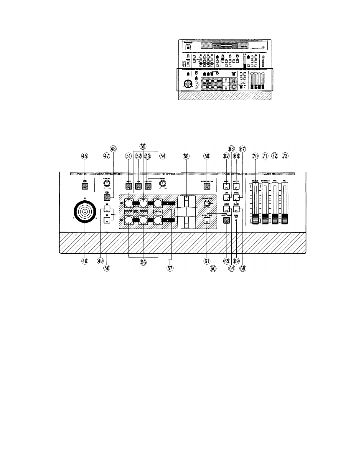
I TOP VIEW 3
• Position Section
45. Position On/Off Button (ON)
This button must be pressed to set the position of a
wipe pattern freely using the Positioner/RGB Control
Joystick (46).
46. Positioner/RGB Control Joystick
This joystick has two functions of setting the position
of a wipe pattern and controlling the hue of the source
video signal (A or B).
When the Position On/Off Button (45) is pressed on,
this joystick functions as the positioner.
When the Color Correction On/Off Button (48) is
pressed on, this joystick functions as the RGB control.
When it is in the center, it generates the original color
of the source video signal.
• Coior Correction Section
47. Chroma Level Control (CHROMA)
This control adjusts the color level of the images from
the Source Video Signal. When this control is set to
the center position, it generated the original color level
of the Source Video Signal.
Note ;
Noise may be recorded on tape when this control
is set to the MAX position if color input signals are
excessive.
48. Color Correction On/Off Button (ON)
This button must be pressed to correct the color of the
source video signal.
- 7
Page 10

49. Color Correction-A Button (A / RESET)
Color correction can be made on the A-bus Source
Video Signal by pressing this button. When you press it
once, the LED starts blinking, the chroma level can be
adjusted by using the Chroma Level Control (47).
When you press it a second time, the LED remains
lighted, and the hue can be adjusted by using the
Position/RGB Control Joystick (46). Chroma level can
also be adjusted by using the Chroma Level Control
(47).
It is also used as Reset Button.
Refer to OPERATION on page 13.
50. Color Correctlon-B Button (B / RESET)
Color correction can be made on the B-bus Source
Video Signal by pressing this button. When you press it
once, the LED starts blinking, the chroma level can be
changed by using the Chroma Level Control (47).
When you press a second time, the LED remains lighted,
the hue can be changed by using the Position/RGB
Control Joystick (46). Chroma level can also be
adjusted by using the Chroma Level Control (47),
It is also used as Reset Button.
Refer to OPERATION on page 13.
56. B-bus Buttons (B)
These buttons are used to select the desired
audio/video signals allocated to the B-bus input. The
Source 1 /2 corresponds to the Source 1 /2 audio/video
inputs on the rear panel of the instrument.
By pressing the Source 1 and 2 buttons on the B-bus
simultaneously, the External Camera Signals can be
selected.
57. MIx/WipeLED
When the A-bus (B-bus) LED remains lighted and the
Wipe / Mix LED blinks, the Wipe / Mix effect is only
partially produced on the A-bus (or B-bus) side.
58. Mix/WIpe Lever
In wipe mode, manually moving this lever between the
A-bus and B-bus will increase the relative portion of
each bus signal according to the option selected. In
mix mode, the audio and video are switched together
on the A-bus and B-bus.
59. Audio Follow Button (AUDIO FOLLOW)
By pressing this button, the audio on the A-bus and
B-bus can be changed according to the relative
percentage position of the Mix/Wipe Lever (58).
• Mix Effect Section
51. Wipe Selection Button (WIPE)
This button is pressed to obtain a wipe effect on the
A-bus Source Video Signal and the B-bus Source Video
Signal depending on the setting of the Wipe Pattern
Select Buttons.
Note :
It is also used as automatic demonstration button.
Press the Power On/Off Button to turn off.
Then press the Power On/Off Button again to
turn on while pressing both of this button and Mix
Select Button (52).
52. Mix Select Button (MIX)
This button is pressed to obtain a mix effect on the
A-bus Source Video Signal and the B-bus Source Video
Signal.
53. Luminance Key Select Button (LUM KEY)
The Luminance Key effect is obtained by pressing this
button and adjusting the Luminance Key Level Control
(54). The B-bus Source Signal must be the key signal.
54. Luminance Key Level Control (LEVEL)
This control is used to adjust the Luminance Key Level.
55. A-bus Buttons (A)
These buttons are used to select the desired
audio/video signals allocated to the A-bus input. The
Source 1 /2 corresponds to the Source 1 /2 audio/video
inputs on the rear panel of the instrument.
By pressing the Source 1 and 2 buttons on the
A-bus simultaneously. External Camera Signals can
be selected.
60. Auto Fade/Take Transition Control (TRANSITION)
This control adjusts the automatic fading/auto-take
interval time from 0 to 510 frames at 2-frame
increments.
61. Auto Take Button (AUTO TAKE)
The auto take effect-Automatic Wipe / Mix-can be
executed by pressing this button. This button lights
during the Auto-take interval.
• Fade Control Section
62. Video Fade Button (VIDEO)
Video program output signal fade-in or fade-out is
available with this button.
Use the Auto Fade Button (65) to select fade-out or
fade-in.
63. DSK Fade Button (DSK)
Downstream Keyed signal fade-in or fade-out is
available with this button.
Use the Auto Fade Button (65) to select fade-out or
fade-in.
64. Audio Fade Button (AUDIO)
Fade-in or fade-out of the audio recording output is
available with this button.
Use the Auto Fade Button (65) to select fade-out or
fade-in.
Note :
The fade-out or fade-in of Head phone output is
cannot be selected.
8-
Page 11

65. Auto Fade Button (AUTO FADE)
Press this button on for fade-out.
The LED on this button will light and the fade-out will
start.
The transition time can be adjusted using the Auto
Fade/Take Transition Control (60).
After fade-out, the LED on this button will go out and
Fade Out Indicator (69) will light.
Note:
The Fade Out Indicator blinks during fade-out.
By pressing this button during fade-out, fade-out
will be stopped on the way.
66. Matte Fade Button (MATTE)
The video fade signal fades out to the selected Matte
Color when this button is pressed.
67. White Fade Button (WHITE)
The video fade signal fades out to white when this
button is pressed.
68. Black Fade Button (BLACK)
The video fade signal fades out to black when this
button is pressed.
69. Fade Out Indicator (FADE OUT)
When this LED remains lighted, fade-out is under way.
When this LED blinks, fade-out/fade-in is still
incomplete.
I FRONT VIEW
74. Headphone Level Control (LEVEL)
The audio level of the headphone can be adjusted with
this control.
75. Headphone Jack (PHONES)
Optional headphone can be connected to this jack.
• Audio Mix Section
70. Source 1 Audio Fader (SOURCE 1)
The audio level of the Source 1 input can be adjusted
by sliding this fader.
71. Source 2 Audio Fader (SOURCE 2)
The audio level of the Source 2 input can be adjusted
by sliding this fader.
72. Aux Audio Fader (AUX)
The audio level connected to the Auxiliary Audio Input
Jack (86) can be adjusted by sliding this fader.
73. Microphone Fader (MIC)
The audio level connected to the Microphone Jack (76)
can be adjusted by sliding this fader.
76. Microphone Jack (MIC)
Optional microphone can be connected to this jack.
77. Title Input Connector (TITLE)
This connector is used to connect the optional
Character Generator WJ-KB50 (recommended).
The pin numbers are as follows.
: Character In
(1)
: Red
(2)
; Ground
(3)
; Green
(4)
: Sync out
(5)
: Blue
(6)
: Ground
(7)
: +9VOut
(8)
: Ground
(9)
(10) : ID
9-
Page 12

I REAR VIEW
78. Source 1 Y/C Input Connector (SOURCE 1-Y/C)
This connector accepts the S-video signal.
Note :
This input has a priority over that of the COMP.
Connector for Source 1. If the S-video signal and
the composite signal are both supplied Source 1
at the same time, only the S-video signal is used
as a Source 1 Video signal.
79. Source 1 COMP. Input Connector
(SOURCE 1/COMP)
This connector accepts a 1.0 Vp-p/75 ohms composite
video signal.
80. Source 1 Audio Input Jacks
(SOURCE 1/AUDIO L/R)
The Source 1 Audio Input Signal can be supplied via
these pin jacks.
81. Source 2 Y/C Input Connector (SOURCE 2-Y/C)
This connector accepts the S-video signal.
Note:
This input has a priority over the COMP. Connector
for Source 2. If the S-video signal and the
composite signal are both supplied to Source 2
at the same time, only the S-vIdeo signal is used
as a Source 2 Video Signal.
82. Source 2 COMP. Input Connector
(SOURCE 2/COMP.)
This connector accepts a 1.0 Vp-p/75 ohms composite
video signal.
83. Source 2 Audio Input Jacks
(SOURCE 2/AUDIO L/R)
The Source 2 Audio Input Signal can be supplied via
these pin jacks.
84. External Y/C Input Connector
(EXT CAMERA IN/Y/C)
The external camera to be used as a Key Source is
connected to this connector when the camera signal
is S-video.
85. External COMP. Input Connector
(EXT CAMERA IN/COMP.)
The external camera to be used as a Key Source is
connected to this connector when the camera signal
is composite video.
86. Auxiliary Audio Input Jacks (AUX AUDIO IN)
The auxiliary audio input signal can be supplied via
these jacks. When an audio signal is supplied to the
L-channel, it is also supplied to the R-channel (mono
mode) internally. When an audio signal is supplied to
the R-channel, it is used for the R-channel only.
87. Program Out-1 Y/C Output Connector
(PROGRAM OUT 1/Y/C)
The S-video Program Output Signal-1 is provided via
this connector.
88. Program Out-1 COMP. Output Connector
(PROGRAM OUT 1/COMP.)
The composite video Program Output Signal-1 is
provided via this connector.
89. Program Out-1 Audio Output Jacks
(PROGRAM OUT 1 L/R)
The audio output signals of R-channel and L-channel
from Program Output 1 are supplied via these pin jacks.
10-
Page 13

90. Program Out-2 Y/C Output Connector
(PROGRAM OUT 2/Y/C)
The S-video Program Output Signal-2 is provided via
this connector.
91. Program Out-2 COMP. Output Connector
(PROGRAM OUT 2/COMP.)
The composite video Program Output Signal-2 is
provided via this connector.
92. Program Out-2 Audio Output Jacks
(PROGRAM OUT2 L/R)
The audio output signals of R-channel and L-channel
from Program Output 1 are supplied via these jacks.
93. Advance Sync Output Connectors (ADV SYNC)
In the A/B Roll Editing System, the Advance Sync signal
from this connector should be supplied to a playback
VTR which does not have a Time Base Corrector (T.B.C.)
inside.
Note:
Enough editing accuracy cannot be obtained
without this signal.
94. GPI Input Connector (GPI)
Refer to "INTERFACE” on page 28 for details.
95. Preview Output Connector (PREVIEW OUT, COMP)
The video effect of the composite video signal is
obtained at this connector regardless of which Program
Out Button is selected, (42) or (43).
96. RS-232C Control Connector (RS-232C)
Ask your the Panasonic Dealer for communication
software.
97. Cooling Fan
98. Main Power Switch (MAIN POWER)
The unit is in stand-by mode when this switch is
pressed on. Unless this switch is pressed on, the unit
will not be on even if the (front panel) Power On/Off
Button (1) is pressed.
11
Page 14

SYSTEM CONNECTION
Monitor
Preview
Monitor
Program
Monitor
The following models (or equivalents) are recommended for
this system. The S-video signal and stereo audio signal are
also recommended to obtain quality edited outputs.
Digital AV Mixer WJ-MX30
Character Generator WJ-KB50
External Camera WV-D5100
Playback VTR AG-7150
Recording VTR AG-7350
Monitor TV
1. Connect coaxial cables between the Advance Sync
Output Connectors (93) on this unit and the Advance
Sync input on both playback VTR 1 and VTR 2.
2. Connect audio cables between the Source 1 Audio
Input Jack (80) / Source 2 Audio Input Jack (83) on
this unit and Audio Output Connector / Audio Input
Connector on the playback VTR-1 / VTR-2 / Recording
VTR, respectively.
3. Connect S-video cables between the Source 1 Y/C
Input Connector (78) / Program Out-1 Y/C Output
Connector (87) on this unit and the S-video Out /
S-video In Connectors on the playback VTR-1 / VTR-2/
Recording VTR, respectively.
4. Connect an S-video cable from the S-video output
connector of the camera to the External Y/C Input
Connector (84) on this unit.
5. Connect a coaxial cable between the Preview Output
Connector (95) on this unit and the Video Input
Connector on the Monitor TV.
12 -
Page 15

OPERATION
A. Pre-Operational Setup
A-1. Power
1. Press the MAIN POWER Switch (98) on located on the
2.
.................
rear panel. The unit is now in stand-by mode. No
operations can be executed yet.
Notes :
• When turning off te MAIN POWER Switch with
the POWER switch ’’OFF", this unit is stand-by
condition by turning on the MAIN POWER switch.
• When turning off the MAIN POWER switch with the
POWER switch ”ON’’, this unit is on condition by
turning on the MAIN POWER switch if the memory
backup is kept.
In this time, if the memory backup is not kept, this
unit is stand-by mode.
Press the Power On/Off Button (1) on the operation
panel. The unit is now in operation mode and the
Cooling Fan (97) located on the rear panel starts to
rotate. The LED’s on the operation panel light up as
shown below.
Field Preset Operation mode
Notes :
1. If you do not use the unit for an extend period of
time or to shut off the power completely, switch
off the MAIN POWER Switch (98).
2. If the Cooling Fan (97) does not rotate, switch it off
and disconnect the AC power cord. Call service
personnel before attempting further use.
3. The modes selected by buttons will be kept by
memory backup approximately 1 week even if AC
power is disconnected.
A-2. Reset
Press the Power On/Off Button (1) off. With both the Color-A
(49) and B (50) Buttons depressed, press the Power On/Off
Button (1) on.
It would be helpful in case of unexpected operational failure.
...............
Factory Preset Operation mode
3. And this status, without still and strobe, is later recalled
when the power is restored if the memory is kept.
B '
D
- 13 -
Page 16

B. Basic Operation 1
B“1. Input/Output Selection
1. Source Selector
The audio/video signal to be input for effects is
selected from the respective options on the A-bus and
B-bus. The selected audio will be controlled by the
AUDIO MIX for the respective A-bus and B-bus.
The audio/video signals to be sent to the PROGRAM
OUT-1, -2 connectors (87) (88) (89) (90) (91) and (92) are
selected by the appropriate PROGRAM OUT Buttons
(42) (43) (44).
In case the Source Video Signal from the A-bus is to be
sent out directly, press the PROGRAM OUT A Button
(42) . (The Matte Signal will not be sent out. The Source
Video whose button is blinking is sent out instead.)
In case the Source Video Signal from B-bus is to be
faded out directly, press the PROGRAM OUT B Button
(43) . (The Matte Signal will not be sent out. The Source
Video whose button is blinking is sent out instead.)
In case the (operation panel processed) effect video
signal is to be sent out, press the EFFECT Button (44).
Note ;
The Source 1 or Source 2 video signal sent out
from the PROGRAM OUT connectors (87)-(92) are
subject to effects by the Color Correction, Digital
Effect, Position, Downstream Key, Mix Effect and
Fade Control. So do not add these effects to the
video if you want to see the original source video
signal.
B-2. Matte
The MATTE GENERATOR generates 9 matte colors to
choose from : Color Bar (C/L BAR), White, Yellow, Cyan,
Green, Magenta, Red, Blue and Black.
Notes
1 When the SOURCE 1 and 2 buttons for A-bus or on
B-bus are simultaneously pressed, External Video
Signal Is available.
The MATTE Button for the A-bus or on B-bus
is invalid in Double Picture scene of the
picture-ln-picture mode.
2. Program Out Selection
To select a (background) matte color, press the
SELECT Button (5) until the desired color is obtained.
To change the chroma level of the selected matte color,
adjust the Matte Color Control (3). The C/L BAR and
BLACK will not be changed. In case WHITE is selected,
the brightness changes from black to white.
When the GRADUATION Button (4) Is pressed
repeatedly, the Matte Color is graduated accordingly
(per the Matte Color Control) from top to bottom as
shown below.
14
Page 17

OFF
Gradation 1
B-4. Color Correction
This function allows color adjustment from a selected
input source, as well as compensation for excessive
color. Using the monochrome effect, a signal tint can
be imposed over on the entire scene image.
Notes :
1. Color Correction will have no effect if the selected
source video is a Black/White signal.
2. The MONO Button (32) for DIGITAL EFFECT should
be off.
3. The same color correction should be made on both
the A-bus and B-bus signals.
Gradation 3
Note :
Gradation 2
When a Matte Color is selected by the Source
Selector, it can be used as an alternate source
signal for the WIPE (51), MIX (52) functions.
However, Matte Color cannot be used in the
following effect operations. In these cases, the
Source Video Signal indicated by a blinking source
button will be displayed instead of the Matte Color
on the monitor automatically.
1. LUM KEY (53) effect
2. DOWN STREAM KEY effect
3. (FADE CONTROL effect)
B-3. Audio Mixer
The WJ-MX30 has 4 audio source inputs; the
Source 1/2, an auxiliary audio input and the external
microphone. Each audio level can be adjusted
ndependently by the audio faders.
•
• Press the Color Correction On/Off Button (48) on.
• To correct the A-bus signal, press the A Button (49)
once. The LED starts blinking. In this case only the
CHROMA Control (47) corrects the color of the A-bus
signal. If you press the A-Button (49) a second time, the
LED lights. The CHROMA Control (47) and the R/G/B
Control joystick (46) are then valid for color correction
of the A-bus signal. To make the color correction
function invalid, press the A Button (49) a third time to
turn off the LED.
• To correct the B-bus signal, press the B-Button (50)
once. The LED starts blinking. In this case only the
CHROMA Control (47) corrects the color of the B-bus
signal. If you press the B-Button (50) a second time,
the LED lights.
The CHROMA Control (47) and the R/G/B Control (46)
are then valid for color correction of the B-bus signal.
To make the color correction invalid, press the B-Button
(50) a third time to turn off the LED.
• The Source 1 Fader (70) adjusts the audio level of the
Source 1 Audio Signal; the Source 2 Fader (71) adjusts
that of the Source 2. The AUX Fader (72) or the MIC
Fader (73) adjusts each respective audio input signal
accordingly.
15 -
Page 18

If the CHROMA Control (47) is turned fully to the
MIN position and the position of the R/G/B Control
(46) to the center, a Black and White video image
is obtained. When adjusting the R/G/B Control (46)
from this position, a mono tone (R/G/B) video image is
obtained.
Notes :
1. A Black and White video image may be obtained
in another way. Press the Color-A Button (49) or
Color-B (50) Button once (The LED blinks). Turn
the CHROMA Control (47) fully to MIN position.
2. When pressing the Color Correction Button to turn
on while turning on the Position On/Off Button, the
LED on the Position On/Off Button blinks for the
stnad-by mode, the positioning scene is kept and
the color correction is available.
B-5. Position Control
The position of a specific wipe pattern can be changed
on the monitor screen using Position Control function.
C. Basic Operation 2
Digital Effect block
The following is a detailed description of the Digital Effect
block function which generates digital special effects for
the A-bus and B-bus source video signals. In order to add
the desired effect(s) to the A-bus (B-bus) signal, press the
A-Button (21) (B-Button (22)) and the ON-Button (20).
Q S D]P P
□i
a
□
Notes :
1.
The selected effect(s) can be added to either the A-bus
or B-bus at one time.
Without pressing the Effect On/Off Button (20), the
digital effect(s) will not added to the A-bus or B-bus
signal.
Q n
Press the Square Wipe Button (13) and select the
desired wipe pattern by pressing this button repeatedly.
Press the Position On/Off Button (45) on. The LED on
this button lights. (Wipe size is doubled.)
Adjust the Mix/Wipe Lever (58) to obtain the desired
wipe size.
Operate the Positioner Joystick (46). The position of a
wipe scene can be changed on the monitor screen.
Negative
Press the NEGA Button (25). A negative image (like a
film negative) is obtained. Color correction can also be
used with this function.
Normal Image
2.
MOSAIC
Press the MOSAIC Button once (24). A mosaic-like or
box-like pattern is obtained. Mosaic pattern size can
be adjusted continuously at 31 steps with SIZE Control
(23).
Negative Image
■ i
L ^
Note :
When pressing the Position On/Off Button to turn
on while turning on the Color Correction On/Off
Button, the LED on the Color Correction On/Off
Button blinks for the stand-by mode and the
corrected color scene is kept and position control
is available.
♦
Normal Image
- 16 -
Page 19

3.
Scramble
Press the MOSAIC Button a second time. The LED on
this button blinks. A scramble-like pattern is obtained.
Scramble pattern size is not adjustable.
7. Strobe
Press the STROBE Button (27). A stroboscopic image
like a series of still images is produced in slow motion
at intervals of 0.03 to 2.1 seconds. These intervals can
be adjusted by the Effect Interval Time Control (26).
Normal Image
4. Monochrome
Scramble Image
Press the MONO Button (32). A black and white image
can be obtained.
5. Paint
Press the PAINT Button (28). An oil-paint touch image
can be obtained. Four kinds of pattern are available.
8. A/V Synchro
Press the A/V SYNCHRO Button (30). The music or
sound supplied to the WJ-MX30 can trigger other
selected Digital Effect(s).
Effected video
6. Still
Press the STILL Button (31). An Instant or frozen image
at any point of the selected video input will be obtained.
Note :
Strobe mode cannot be used In Still mode. Still
mode becomes off automatically.
Notes :
1. The trigger threshold can be adjusted by the
LEVEL Control (29).
2. A/V Synchronization holds the desired effect(s) of
Nega, Mosaic, Mono, Paint and Still for a certain
period once triggered. The holding time varies as
shown below.
Audio
A/V Synchronization holds the Strobe effect for
the period a'djusted by the Effect Interval Time
Control (26).
17
Page 20

D. Basic Operation 3
Mix and Wipe Block
The following is a detailed description of the Mix and Wipe
block, which consists of three functions
Luminance Key.
.......
Mix, Wipe and
D-1. Mix
# Press the MIX Button (52).
• Select source signals from the A-bus (55) and B-bus
(56). In case the MATTE color is selected, color choice
is available with the SELECT buttons (5) in the MATTE
GENERATOR section.
D-2. Wipe
Wipe patterns are produced from the WIPE PATTERN
block as shown below.
® (|)(® (n)
3 c D 1
1 J
, - - - ‘S
vJr.^SB O SI
^ ’DfDi'Df D]
I MULTI TE555T
□ □ □ □
(i|) ® (@) ®
1. Wiping
• Press the WIPE Button (51).
• Select source signals from the A-bus (55) and the
B-bus (56). In case MATTE is selected, color choice
is available with the SELECT buttons (5) in the MATTE
GENERATOR section.
• Select and press the desired Wipe Pattern Select
Button.
• Select and press the desired the Wipe Edge Buttons
and Wipe Direction Buttons.
• Operate the Mix/Wipe Lever (58) from A-bus to B-bus,
or vice versa. Wipe is thus performed.
• Notice that the Mix/Wipe LED’s (57) light as follows.
(1) A-bus : ON ^ A-bus image fully displayed on the
screen.
(2) A-bus: Blinking —> The Mix/Wipe Lever (58)
moves to halfway done.
(3) B-bus : Blinking The Mix/wipe Lever (58) moves
after halfway done.
(4) B-bus : ON B-bus image fully displayed on the
screen.
Notes :
1. Wipe patterns can be generated using the Wipe
Pattern Select Buttons.
2. Each generated wipe pattern can be selected for
the Wipe Edge function and the Wipe Direction
function by pressing the appropriate Wipe Edge
Buttons and Wipe Direction Buttons.
Operate the Mix/Wipe Lever (58) from the A-bus to
B-bus, or vice versa to perform the desired mixing.
Notice that the following Mix/Wipe LED’s (57) light as
appropriate.
(1) A-bus : ON ^ A-bus image fully displayed on the
screen.
(2) A-bus : Blinking —> A-bus image (stronger) and
B-bus image (weaker) on the screen.
(3) B-bus: Blinking -> A-bus image (weaker) and
B-bus image (stronger) on the screen.
(4) B-bus : ON —>■ B-bus image fully displayed on the
screen.
2. Wipe Edge
• Press the Edge Button (16) once to add a narrow border
between wipe images. By pressing the same button a
second time, the border becomes wide. A third press
of the button makes a faint border between the two
video Images at the wipe margin. (No matte colors
available.) A fourth press of the button eliminates the
border entirely.
• Press one of the Matte Color Selectors (5) to select
and add the desired color to the border. (The
complementary color of Matte Color is applied.)
18 -
Page 21

Narrow Border
with Matte Colour
Wide Border
with Matte Colour
Faint border
without Matte Colour
Note :
In case of the picture-in-picture mode, 5 types
border is available by pressing the Edge Button
repeatedly as shown below.
once press a narrow border
second press wide border
third press faint border
fourth press shadow
• Press the REVERSE Button(19). The movement of the
wipe scene is reversed.
• Press both the ONE-WAY Button (18) and REVERSE
Button (19). The combination of these two functions
will allow for symmetrical screen wiping.
(Shadow)
fifth press shadow with border
(Shadow with
border)
Sixth press of this button eliminates the border
entirely.
3. Wipe Direction
• Press the ONE-WAY Button (18). The wipe scene moves
the same way each time the Mix/Wipe Lever (58) is
operated.
D-3. Luminance Key
• Move the Mix/Wipe Lever (58) all the way to the B-bus
position.
• Press the LUM KEY Button (53).
• Adjust the LEVEL Control (54) to the desired clear key
picture threshold.
Note :
By adjusting the Mix/Wipe Lever (58) to the A-bus
position, a mixing effect can be obtained.
- 19 ■
Page 22

D-4. Pattern Table
• Up to 107 wipe patterns are available using the Pattern Selection Buttons (28 patterns).
20 -
Page 23

21
Page 24

D-5. Picture-in-Picture
Press the WIPE Button (51) to turn on.
Press the Picture-in-Picture Button (12). Move the
Wipe/Mix Lever (58) to the B-bus position from the
A-bus position. The following patterns can be selected
by pressing this button.
Double Picture-in-Picture mode
By using the Positioner Joystick (46), the position of
the picture-in-picture scene can be changed on the
monitor scene.
Notes :
• When pressing this button fourth times (Double
Picture-in-Picture mode), Matte Color cannot be
selected.
• In the Double Picture-in-Picture mode, the
picture quality is not same with it of single
Picture-in-Picture mode.
• In the Double Picture-in-Picture mode, position
control is available only up or down direction.
E. Basic Operation 4
E-1. Downstream Key
The following is a detailed description of the
Downstream Key block. This function is mainly used for
superimposing characters or letters for a telopper. The
optional Character Generator WJ-KB50 can be used
for this purpose.
Set the KEY LEVEL Control (33) to the end low position.
Select and press the FILL MATTE Button (37) for
a Key-Fill signal. The Key-Fill signal fills the key
signal. When the FILL MATTE Button (37) is pressed,
the desired color can be chosen from the MATTE
GENERATOR.
Press the EXT. CAMERA Button (40) for a Key Signal,
(or A-Button (35) or B-Button (36) can be selected)
Press the ON Button (34).
Adjust the KEY LEVEL Control (33) to obtain a clear
edge key image.
Example of using the title card option
In case a title is written on a black card, adjust the KEY
LEVEL Control (33) to obtain a clear edge key image.
Notes :
1. When the optional Character Generator WJ-KB50 is
used for a key source, set the KEY LEVEL Control (33)
to the low end position.
2. A jittery EXT. CAMERA signal or a jittery VTR playback
signal can cause a disturbance in synchronization.
22
Page 25

• When the REVERSE Button (41) is pressed, the keyed
image and the background image will be reversed.
Normal
Two types (shadow, border) and five kinds of edges
are available with the EDGE Button (39).
Reversed
E-2. External Key
Wipe can be made on the image of A using patterns
with signals supplied from an external camera.
And the image of B can be displayed In the external key
pattern.
• Supply external camera output signals to this mixer.
Normal Narrow Border
Wide Border
Narrow Shadow Wide Shadow Drop Shadow
Notes :
1. When a Key image is white, any of 9 colors can be
selected for the threshold edge, solid or graded,
by pressing the Matte Color Selector (5) and the
Graduation Button (4).
2. Matte Color key images always have a black edge.
3. When a line color setting is made at the WJ-KB50,
press the Fill-matte Button (37) and select the C/L
Bar position.
When selecting the Matte Button for Bus Input or
Fade Block, matte color setting is also made at the
WJ-KB50.
In this time, the up and down of the screen cannot
be displayed.
4. When the Double picture-in-picture mode is
selected with the WJ-KB50 use, WHITE Button
(38) is selected automatically.
And a line color setting can be made at the
WJ-KB50.
In this time, the up and down of the screen cannot
be displayed.
5. When using the WJ-KB15, the color setting from
the WJ-KB15 is not available.
• Press the Split Wipe Button (15) four times.
• The LED on this button blinks.
• Move the Wipe/Mix Lever (58) to the B-bus position
from the A-bus position.
• Adjust the Key Slide Control (33) to obtain a clear edge
wipe image.
Notes :
• When the video signal of B-bus is the same as
that it of the external camera, the perfect pattern
may be not available due to the condition of the
contrast of the pattern.
• When pressing the Reverse Button (19), Image of
A and B shown the above will be reversed.
• The External Camera Pattern should be white on
a black base.
• The External Camera Pattern can be edged using
the Wipe Edge Button (16).
-23-
Page 26

F. Basic Operation 5
Fade
Synchronized fading makes it possible to operate the
Video, Downstream Key and Audio fades together, or in
any combination. Each of the three can be controlled
independently via Auto Fade. The following area shows
the FADE CONTROL section.
The VIDEO (62), DSK (63) and /or AUDIO (64) signals can
fade out to one of the following : MATTE (66), WHITE (67),
BLACK (68) signal.
Note :
Auto-fade can be stopped by pressing the Auto
Fade Button (65).
The LED on the VIDEO Button (62) blinks while auto
fade is in the stopping process. Auto-fade starts
again when the Auto Fade Button(65) Is pressed.
F-2. Down stream Key Fade-Out (In)
• Adjust the TRANSITION Control (60) to the desired auto
fade time.
• Press the DSK Button (63).
• The LED on this button lights.
• Press the Auto Fade Button (65) to execute the auto
downstream fade.
• The LED on this button lights.
• Fade Out Indicator (69) starts blinking (as the fade-out
progresses).
• After fade-out, the Fade Out Indicator remains lighted.
• Fade-in operation is made by pressing the Auto Fade
Button (65) when the Fade Out Indicator remains
lighted.
After Fade-in, the Fade Out indicator and LED on the
Auto Fade Button go out.
V. *
*
▲
* 1
F-1. Video Fade-Out (In)
• Adjust the TRANSITION Control (60) to the desired auto
fading time.
• Press the VIDEO Button (62).
• The LED on this button lights.
• Press the Auto Fade Button (65).
• The LED on this button lights.
• Fade Out Indicator (69) starts blinking (as the fade-out
progresses).
• After fade-out, the Fade Out Indicator remains lighted.
• Fade-in operation is made by pressing the Auto Fade
Button (65) when the Fade Out Indicator remains
lighted.
After Fade-in, the Fade Out Indicator and LED on the
Auto Fade Button go out.
Note :
Auto-fade can be stopped by pressing the Auto
Fade Button (65).
The LED on the DSK Button (63) blinks while auto
fade is in the stopping process. Auto-fade starts
again when the Auto Fade Button (65) is pressed.
-24 -
Page 27

F-3. Audio Key Fade-Out (In)
• Adjust the TRANSITION Control (60) to the desired auto
fading time.
• Press the Audio Fade Button (64).
• The LED on this button lights.
• Press the Auto Fade Button (65) to execute the auto
audio fade.
• The LED on this button lights.
• Fade Out Indicator (69) starts blinking (as the fade-out
progresses).
• After fade-out, the Fade Out Indicator remains lighted.
• Fade-in operation is made by pressing the Auto Fade
Button (65) when the Fade Out Indicator remains lightly.
After Fade-in operation, the Fade Out Indicator and LED
on the Auto Fade Button go out.
Notes :
1. Auto-fade can be stopped by pressing the Auto
Fade Button (65).
The LED on the AUDIO Button blinks while auto
fade is in the stopping process. Auto-fade starts
again when the Auto Fade Button (65) is pressed.
G. Basic Operation 6
2. The headphone audio does not fade.
3. When MATTE, WHITE or BLACK is selected for a
fade out scene, no sound comes out.
Remarks :
1. Any combination of VIDEO, DSK and/or AUDIO can be
selected for fading.
2. The fade-out of the video signal Is;
the selected matte color using MATTE Button (66), the
white background using WHITE Button (67), the Black
background using BLACK Button (68).
3. Only the outputs selected for fading are processed.
Example 1 :
If the VIDEO Button (62) is chosen without the
DSK Button (while the Downstream key function is
activated), the video portion of the final image will
fade and the Downstream Key image will remain
on the screen, unfaded.
Audio Follow
Audio can be processed either separately or in conjunction
with video source selection.
The Audio Follow provides automatic audio ratio mixing
(between Source 1 and Source 2 Inputs) via the Mix/Wipe
Lever (58) according to the ratio of Source 1 and Source 2
inputs as effected.
• The mode except
Picture-in-Picture mode
• PIcture-in-Picture mode
A B
Audio
Output
B-bus
A B
Audio
Output
• Press the AUDIO FOLLOW Button (59)
• Adjust the Mix/Wipe Lever (58) to the A-bus or B-bus
position,
• The audio level ratio between the A-bus and B-bus
changes according to the position of the Mix/Wipe
Lever (58).
• Double Picture-in-Picture mode
A B
Audio
Output
A B
Audio
Output
A B
Audio
Output
A B
Audio
Output
A-bus
A B
Audio
Output
Note :
If AUX and/or MIC inputs are used, they are controlled directly via their respective faders (72), (73) - i.e. they are free of
control by the Audio Follow function.
A-bus
B-bus
25
Audio
Output
A-bus
A B
Audio
Output
Page 28

H. Applications
H- 1. Event Memory Functions
Customized effect combinations can be stored in
the Event Memory, and later recalled for subsequent
access. The STORE Button (6) is used to store the
desired effects.
Caution:
The event memory will disappear in a few days if
the Main Power Switch (98) is kept off.
• To exit the Event Memory mode.
Press the RECALL Button (7) again.
® ® (9)® (jj
EB EÜ
Jr..gB o IS P..P
_
’QtD]"[q}i*[c3"
□
□
□
□
(Z)
• To clean/reset the eight memories.
Press POWER Button (1) to turn off. Then, while holding
down both STORE Button (6) and RECALL Button (7)
press POWER Button (1).
POWER
RECALL
H-2. Auto Take
• Press the RECALL Button (7).
Instead of the lever controlled Mix and Wipe using
the Mix/Wipe Lever (58), automatic Mix and Wipe
operations can be made using the Auto Take function.
Two kinds of Auto Take are available.
1.
Standard Auto Take
Set up a Wipe Pattern and Digital Effect as desired.
Adjust the TRANSITION Control (60) to the desired auto
take time.
Press the AUTO TAKE Button (61).
Auto-Take can be stopped by pressing the AUTO
TAKE Button (61). The LED’s on both A-bus and
B-bus buttons blink while Auto-Take is in the stopping
process. Auto-take starts again when the AUTO TAKE
Button (61) is pressed again.
2.
Memory Auto Take
Press the RECALL Button (7).
Select and recall the programmed memory by pressing
the EVENT NO. Buttons (8) - (15).
Press the AUTO TAKE Button (61). The program recalled
from the memory is performed. After this, the next Event
Number is selected automatically.
Press the AUTO TAKE Button (61) again. Another
program is performed.
The programs is in memory can be recalled and
performed one after another by pressing the AUTO
TAKE Button (61) repeatedly.
Auto-Take cannot be stopped on the way in the Event
Memory mode.
• To set a Memory location.
Choose desired effects on the panel. When the correct
combination is selected, press STORE Button (6), then
press the appropriate EVENT NO. Buttons (8) - (15). The
LED on the EVENT NO. Button (8) - (15) blinks 3 times,
then goes out when memory is completed.
I B H E B
’d ‘d'd ‘d
d d d d
•
• To recall an event setting, press the RECALL Button
and correct the EVENT NO. Button (8) - (15), then press
the AUTO TAKE Button (61).
Note :
Up to eight preset event combinations are
available. In executing Auto Take successively,
each memory operation will be performed in
sequence according to the numerical locations
used, i.e. only stored numbers will be "toggled”
through. So if the No.3 event is skipped in event
memory setting, it will also be skipped when the
AUTO TAKE Button (61) is pressed.
H-3. Digital Effects
Many unique Digital Effects are available using this
Digital AV Mixer. By combining specific digital attributes
an experienced user can generate a host of tailored
processes for specific applications. Each can be
stored in a memory location (Event Memory) for instant
recall. Below are a couple of sample combinations.
1. Auto-Take
Select the same source input for both the A-bus and
B-bus then adjust 2 different digital effect versions
which can then be mixed or wiped over each other as
desired. For example...
• To reset the functions to the factory set mode, press
the POWER Button (1) off. Then while holding down
both color-A (49) and B (50) Buttons, press POWER
Button (1).
• Press and activate the PAINT Button (28) and STROBE
Button (27) for the A-bus version. The Mix/Wipe Lever
(58) should be turned to A-bus position at this moment.
• Turn the Mix/Wipe Lever (58) to the B-bus position.
• Press the B-Button (22) on the DIGITAL EFFECT block.
• Press the NEGA Button (25).
• Adjust the TRANSITION Control (60) down to "MIN”
position.
-26-
Page 29

Then press the AUTO TAKE Button (61) repeatedly. Two
versions adding different digital effects instantly can be
switched.
A-bus
Paint + Strobe
2. Mosaic-Spotlight
• To reset the functions to the factory set mode, press
the POWER Button (1) off. Then while holding down
both color-A (49) and B (50) Buttons, press POWER
Button (1).
• Select the same source input for both the A-bus and
B-bus.
• The A-bus should have no Digital Effects applied to it
by pressing A-Button (A).
• Turn the Mix/Wipe Lever (58) to the B-bus position.
• Press the B-Button (22) on the DIGITAL EFFECT block.
• Press the MOSAIC Button (24).
• Press the Square Button (13) on the WIPE PATTERN
block.
• Adjust the Mix/Wipe Lever (58) to obtain the desired
wipe size.
• Press the Positioner ON/OFF Button (45).
• The Positioner Joystick (46) now controls the location
of the mosaic image.
• If the border is desired to highlight the "anonymous”
area, press the EDGE Button (16) on the WIPE PATTERN
block.
• If the Reverse function (REVERSE Button (12)) and/or
the Monochrome function (MONO Button (32)) is added,
more highlight effect can be produced.
B-bus
Negative
3. After Image
• To reset the functions to the factory set mode, press
the POWER Button (1) off. Then while holding down
both color-A (49) and B (50) Buttons, press POWER
Button (1).
• Select the same source input for both the A-bus and
B-bus.
• Press the STROBE Button (27).
• Press the MIX Button (52).
• Adjust the TIME Control (26) and Mix/Wipe Lever (58)
to obtain the necessary After Image.
• If required, press the A/V Synchro Control (29) to
synchronize this effect to the audio.
Bus A
Bus B
-27-
Page 30

INTERFACE
1. GPI (General Purpose Interface)
The Auto Take function is activated at the point of the
following edge of the GPI pulse .
GPI
WJ-MX30
Pre-roll
No.1 (A-bus)
A/B
No.2 (B-bus)
1
Transition 0
(MIN)
GPI 1.
When the above signal is used as a GPI signal, follow the
procedure shown below.
1. Select the video signal of A-roll for the A-bus signal
and the video signal of B-roll for the B-bus signal.
2. Set the Wipe/Mix Lever to the A-bus position.
3. Set the video signal of the A/B - roll to the desired
pattern (Mix/Wipe, Wipe Pattern or the like)
4. Set the Auto Fade/Take Transition Control to the 0
position.
5. Store this condition in Event Number Button 1.
6. Set the Wipe/Mix Lever to the B-bus position and
adjust the Auto Fade/Take Transition Control to the
desired interval.
7. Store this condition to Event Number Button 2.
8. Press the RECALL Button and then Event Number
Button 1.
Editing is made with the Event Number 1 condition (A-roll)
at the point of the pre-roll.
The A/B-roll is activated at its point with the transition time
stored in the Event Number 2.
Event Memory Functions
The following set can be stored by the Event Memory
Functions.
1. Setting of the all buttons.
2. Setting of the following controls.
• Transition time
• Position
• Color correction level
• Mosaic size
• Key level
The Event Memory Functions can be activated by pressing
Auto Take Button.
Transition Time
(No.2)
Conversion Cable information
Make the required conversion
cable referring to the
following wiring information.
RS-232C
25-pin
2 TXD
3 RXD
4 RTS
5 CTS
6 DSR
7 SIG. G
20 DTR
■MX30
WJ-
9-pin
SPARE
1
2 RXD
3 TXD
4 DTR
SIG.G
5
7 SIG.G
8 RTS
SPARE
9
(DCE CONNECTION)
Refer to the table below for the transmitting protocol in
connecting the RS-232C to the DT/WJ-MX30.
1
BAUD RATE
2 CHAR SIZE
3 PARITY
4 STOP BIT
5
FLCTRL
Note :
9600 bps
7 bits
Odd
1 bit
RTS/CTS
Be sure to supply the signals for the RS-232C
according to the above table.
- 28 -
Page 31

SPECIFICATIONS
Source Input:
Composite Video Input:
S-Video Input:
Audio Input:
Auxiliary Audio Input:
Microphone Input:
External Camera Input:
GPI Input:
Character (TITLE) Input:
Program Output:
Composite Video Output:
S-Video Output:
Audio Output:
Preview Output:
Advance Sync Output:
Headphone Output:
Digital Effects:
Matte Colors:
Wipe Patterns :
Joystick Control:
Audio Mixer:
Others:
Video Sampling :
Frequency Range :
Frequency Response :
Gain :
S/N (Typical) :
Power Source :
Power Consumption :
Ambient Operating Temperature :
Ambient Operating Humidity :
Dimensions :
Weight :
X 2 (SOURCE 1/2)
1.0 Vp-p/75 ohms, NTSC signal, BNCx2
Y signal; 1.0 Vp-p/75 ohms, C signal; 0.286 Vp-p/75 ohms.
Mini DIN 4 connectorx2
SOURCE 1 /2; Pin-jackx2, —6 dBs/20 Kohms (Unbalanced), Left and Right.
XI (Aux)
—6 dBs/20 Kohms, Pin-jack (Unbalanced), Left and Right
—60 dBv/600 ohms, unbalanced, tip-ring-sleeve type phone jackx 1
1.0 Vp-p/75 ohms, NTSC composite signal, BNCx 1
Y signal; 1.0 Vp-p/75 ohms, C signal; 0.286 Vp-p/75 ohms,
Min DIN 4 connectorxl
Make-contact, BNCxi
10-pin connectorxl for optional Character Generator WJ-KB15,
WJ-KB50
X 2 (PROGRAM OUT 1/2)
1.0 Vp-p/75 ohms NTSC signal, BNCx2
Y signal; 1.0 Vp-p/75 ohms, C signal; 0.286 Vp-p/75 ohms,
Min DIN 4 cohnectorx2
PROGRAM OUT 1 /2; Pin Jackx2, —6 dBs/1 Kohms (Unbalanced) Left and Right.
1.0 Vp-p/75 ohms, NTSC composite signal, BNCxi
4 Vp-p/75 ohms, BNCx2
—20 dBv —80 dBv, 8 ohms unbalanced, tip-ring-sleeve type phone jackx 1
Nega, Mosaic, Mono, Paint, Still, Strobe, A/V Synchro
Color Bar,White, Yellow, Cyan, Green, Magenta, Red, Blue, Black.
107 Patterns
Positioner, Color Correction
Source 1, Source 2, AUX, Mic
Audio-Follow, Auto-Take, Auto-Fade, Memory
4:1: 1, Y=14.3 MHz (910 fH), 8-bit component
Sync; 15.734 KHz±300 Hz
SC; 3.579545 MHzd=40 Hz
Y/C signal; 4.5 MHz (at -3 dB)
Composite Video Signal; 4.5 MHz (at —3 dB)
Audio; 20 - 20 KHz (at -3 dB)
Unity (Video)
56 dB (S-Video), 50 dB (Composite), 70 dB (Audio at 1 KHz)
120V AC, 60 Hz
Operation mode; Approximately 27W
Stand-by mode; Approximately 4W
0-40°C
Less than 90X
18-7/8” (W) X 5-3/16" (H) X 12-1/8” (D)
480 (W) X 132 (H) X 308 (D) mm
10.3 lbs. (4.7 kg)
Weight and dimensions indicated above are approximate.
Specifications are subject to change without notice.
OPTIONAL ACCESSORIES
• Character Generator ..................................................... WJ-KB15, WJ-KB50
■29
Page 32

Panasonic
Broadcast & Television Systems Company
Division of Matsushita Electric Corporation of America
Executive Office: One Panasonic Way, Secaucus, NJ 07094
For further information on our complete line of
Broadcast and Television Systems products,
please call 1-(800) 524-0864 for your nearest
Panasonic regional sales office.
MATSUSHITA ELECTRIC OF CANADA UMITED
5770 Ambler Drive, Mississauga, Ontario, Canada L4W 2T3 (416) 624-5010
PANASONIC SALES COMPANY
DIVISION OF MATSUSHITA ELECTRIC OF PUERTO RICO, INC.
San Gabriel Industrial Park, 65th Infantry, Ave. KM. 9.5 Carolina, Puerto Rico 00630 (809) 750-4300
N0293-0 YWV8QA2941AN
Printed in USA
® 13
 Loading...