

Panasonic WJBP65E01 - NETWORK BOARD Operating Instructions Manual

Network Board
Operating Instructions
Model No. WJ-PB65E01
Video Output Board 1 Only
Nework OUT X-1
ALARM OUT 1
ALARM OUT 2
10/100 BASE-T
Before attempting to connect or operate this product, please read these instructions carefully and save this manual for future use.
Along with this document, refer to Central Processing Unit
WJ-MPU955A Operating Instructions for major operating
References
controls, their functions, and switch settings.
Preface
Network Board WJ-PB65E01 is designed for the connection
with Central Processing Unit WJ-MPU955A and system
expansion of Matrix Switcher WJ-SX650 Series.
Trademarks and Registered Trademarks
• Microsoft and Windows are either registered trademarks or trademarks of Microsoft Corporation in the
United States and/or other countries.
• Intel and Pentium are trademarks or registered trademarks of Intel Corporation or its subsidiaries in the
United States and other countries.
• Other names of companies and products contained in
these operating instructions may be trademarks or registered trademarks of their respective owners.
CAUTION: These servicing instructions are for use by qual-
ified service personnel only. To reduce the risk of electric shock do not perform any servicing other than that
contained in the operating instructions unless you are
qualified to do so.
• Do not attempt to disassemble the apparatus.
To prevent electric shock, do not remove screws or
covers.
There are no user-serviceable parts inside. Contact
qualified service personnel for maintenance.
Precautions
• Do not strike or give a strong shock to the apparatus.
It may cause damage or allow water to enter the apparatus.
• Pay attention to static electricity
Make certain to keep boards inside the anti-static sack
until it is installed.
Put your hand on a metallic surface, other than the
boards to discharge static electricity before installation.
Do not touch components mounted on the boards
directly by hand.
Hold only both edges of the boards when installing.
2
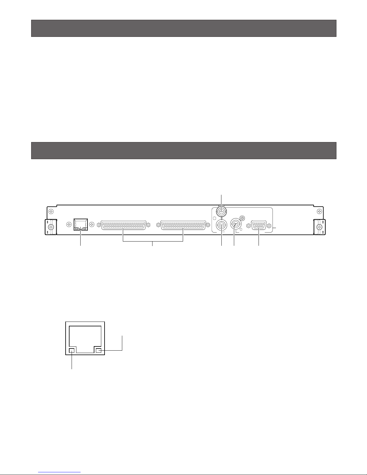
Major Operating Controls and Their Functions
■ Front View
NETWORK OUT X-1
ALARM OUT 2
ALARM OUT 1
SERIAL
VS OUT
VS IN
VS OUT
(THRU)
Video Output Board 1 Only
10/100 BASE-T
q r yt
e
w
q Ethernet Port (10/100BASE-T)
This port is used for connection with Central Processing
Unit WJ-MPU955A via an Ethernet network.
LINK indicator: This indicator lights up when the matrix
switcher is linked to a network through this port.
ACT indicator: This indicator lights up when the matrix
switcher receives or sends data through this port.
w Alarm Output Ports 1, 2 (ALARM OUT 1, 2)
Supplies alarm output signals controlled by Central
Processing Unit WJ-MPU955A.
Note: Refer to WJ-SX650 Series Operating Instructions
for the ALARM OUT port details. (Pin Nos. 3, 5, 7, 9,
12, 14, 16, 18, 36, and 37 are unavailable.)
e VS Input Connector (VS IN)
Accepts a VS input signal from an external device.
r VS Output Loop-thru Connector (VS OUT (THRU))
Loops through VS input signals supplied to e.
t VS Output Connector (VS OUT)
Supplies VS output signals to external devices. While e
is accepting a VS input signal, t supplies an output
signal synchronizing the VS input signal. While e is not
accepting the VS input signal, t supplies an internal
synchronization output signal.
y Serial Port (SERIAL)
Connects to a PC.
LINK indicator
ACT indicator
Features
• With this board, the network connection between
Central Processing Unit WJ-MPU955A and Matrix
Switcher WJ-SX650 Series becomes available to
expand the system composition. Up to 512 cameras
and 64 monitors become connectable.
3
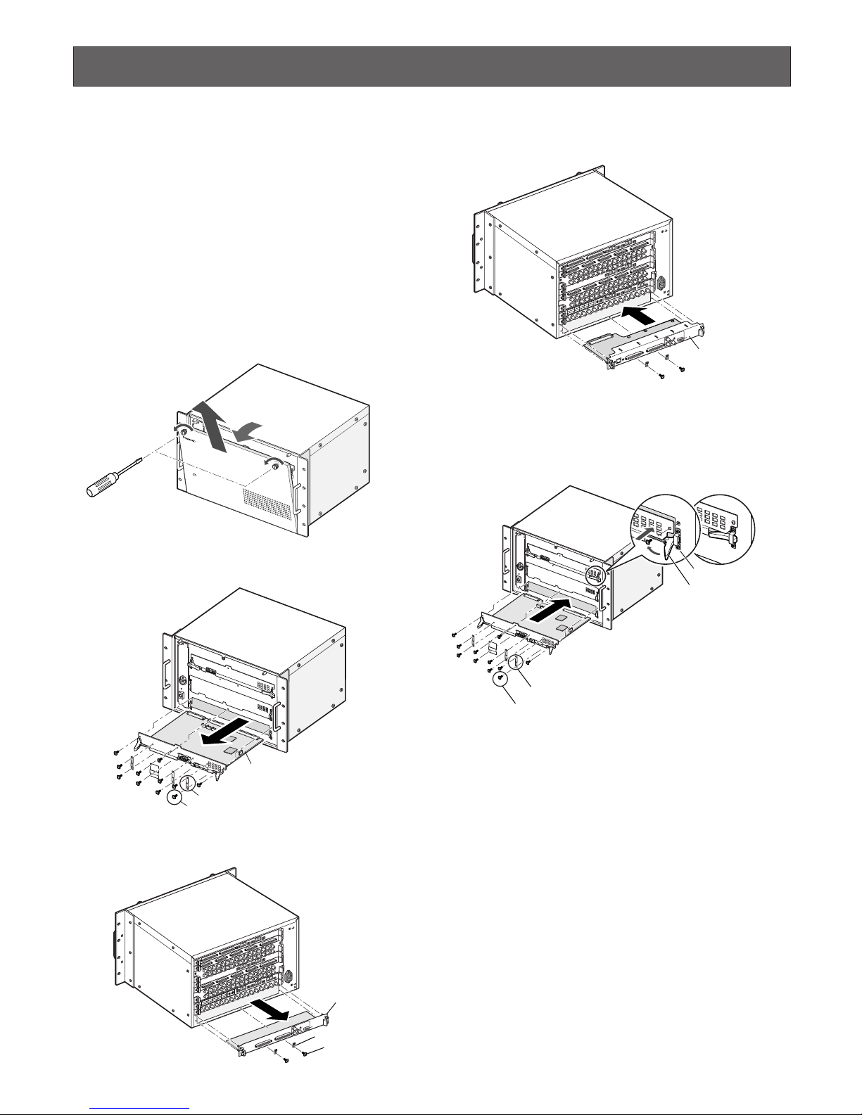
Board Mounting Procedure
The following example is the procedure to mount a network
board into the OUT X-1 slot of WJ-SX650 Series.
Notes:
• This network board can be inserted into the OUT X-1
slot only.
• Before the procedure, power off WJ-SX650 Series.
• Remove the screws and fixing brackets surely when
dismounting.
• Fix the screws surely when mounting.
• Do not hit the boards against the chassis of WJ-SX650
Series.
1. Remove the front panel by loosening the screws.
2. Dismount the video output main board from the front
side.
3. Dismount the OUT X-1 board from the rear side.
4. Mount the network board into the OUT X-1 slot, and fix
the board with the supplied screws.
5. Mount the video output main board by hooking the
board stoppers on the board stopper angles at the front
side, by pushing down the board stoppers, and by fixing the screws. Then, attach the front panel.
Note: When mounting, insert the main board surely into
slits.
Matrix Switcher WJ-SX
650
OPERATE
Video output main board
Fixing brackets (x4)
Screws (x8)
S
IG
N
A
L
G
N
D
S
IG
N
A
L
G
N
D
T
E
R
M
.
O
N
O
N
M
O
D
E
T
E
R
M
.
O
F
F
M
O
D
E
D
A
T
A
4
H
D
R
4
/T
M
N
L
8
H
D
R
2
/T
M
N
L
4
D
A
T
A
3
H
D
R
3
/T
M
N
L
7
H
D
R
1
/T
M
N
L
3
D
A
T
A
2
T
M
N
L
6
T
M
N
L
2
D
A
T
A
1
T
M
N
L
5
T
M
N
L
1
/P
S
D
A
T
A
V
id
e
o
O
u
tp
u
t B
o
a
r
d
2
V
id
e
o
O
u
tp
u
t B
o
a
r
d
1
OUT X-1 board
Fixing brackets (x2)
Screws (x2)
SIGNAL GND
S
IG
NA
L G
ND
T
E
R
M
.
O
N
O
N
M
O
D
E
T
E
R
M
.
O
F
F
M
O
D
E
D
A
T
A
4
H
D
R
4
/
T
M
N
L
8
H
D
R
2
/
T
M
N
L
4
D
A
T
A
3
H
D
R
3
/T
M
N
L
7
H
D
R
1
/T
M
N
L
3
D
A
T
A
2
T
M
N
L
6
T
M
N
L
2
D
A
T
A
1
T
M
N
L
5
T
M
N
L
1
/P
S
D
A
T
A
V
i
d
e
o
O
u
tp
u
t B
o
a
r
d
2
V
i
d
e
o
O
u
t
p
u
t
B
o
a
r
d
1
Network board
Board stopper angle
Board stopper
• Mount the main board into the slot.
• Fix the board with the screws (x3).
• Attach the fixing brackets (x4) with the screws (x8).
Fixing brackets (x4)
Hook the board stoppers
on the board stopper angles, and
push down the board stoppers.
Screws (x8)
 Loading...