

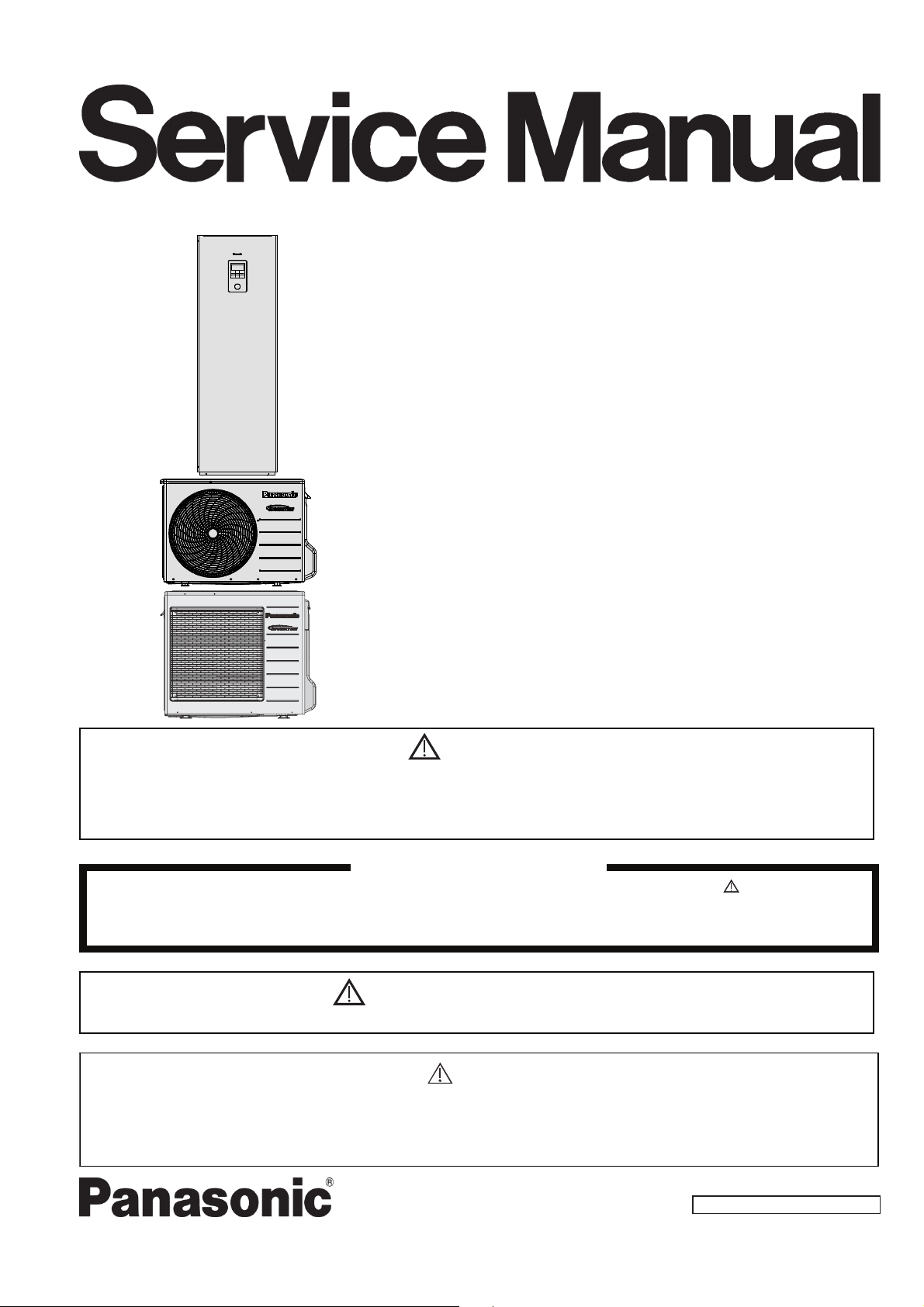
Panasonic WH-UD05JE5, WH-UD03JE5, WH-UD07JE5, WH-ADC0309J3E5UK, WH-UD09JE5 Service Manual
Order No: PAPAMY1905040CE
Air-to-Water Hydromodule + Tank
Indoor Unit Outdoor Unit
WH-ADC0309J3E5UK
WH-UD03JE5
WH-UD05JE5
WH-UD07JE5
WH-UD09JE5
Destination
UK
WARNING
This service information is designed for experienced repair technicians only and is not designed for use by the general public.
It does not contain warnings or cautions to advise non-technical individuals of potential dangers in attempting to service a product.
Products powered by electricity should be serviced or repaired only by experienced professional technicians. Any attempt to
service or repair the products dealt with in this service information by anyone else could result in serious injury or death.
There are special components used in this equipment which are important for safety. These parts are marked by in the Schematic
Diagrams, Circuit Board Diagrams, Exploded Views and Replacement Parts List. It is essential that these critical parts should be
replaced with manufacturer’s specified parts to prevent shock, fire or other hazards. Do not modify the original design without permission
of manufacturer.
In order to avoid frostbite, be assured of no refrigerant leakage during the installation or repairing of refrigerant circuit.
R32 REFRIGERANT
THIS PRODUCT MUST ONLY BE INSTALLED OR SERVICED BY QUALIFIED PERSONNEL.
Refer to National, State, Territory and local legislation, regulations, codes, installation & operation manuals, before the
installation, maintenance and/or service of this product.
– This Air-to-Water Hydromodule + Tank contains and operates with refrigerant R32.
IMPORTANT SAFETY NOTICE
PRECAUTION OF LOW TEMPERATURE
CAUTION
© Panasonic Corporation 2019.

TABLE OF CONTENTS
1. Safety Precautions ............................................. 4
2. Precaution For Using R32 Refrigerant ............. 7
3. Specifications ................................................... 12
3.1 WH-ADC0309J3E5UK WH-UD03JE5 ........ 12
3.2 WH-ADC0309J3E5UK WH-UD05JE5 ........ 16
3.3 WH-ADC0309J3E5UK WH-UD07JE5 ........ 20
3.4 WH-ADC0309J3E5UK WH-UD09JE5 ........ 24
4. Features ............................................................. 28
5. Location of Controls and Components .......... 29
5.1 Indoor Unit ................................................... 29
5.2 Outdoor Unit ................................................. 48
6. Dimensions ....................................................... 49
6.1 Indoor Unit ................................................... 49
6.2 Outdoor Unit ................................................. 50
7. Refrigeration and Water Cycle Diagram ........ 52
8. Block Diagram .................................................. 53
8.1 WH-ADC0309J3E5UK WH-UD03JE5
WH-ADC0309J3E5UK WH-UD05JE5 ........ 53
8.2 WH-ADC0309J3E5UK WH-UD07JE5
WH-ADC0309J3E5UK WH-UD09JE5 ........ 54
9. Wiring Connection Diagram ............................ 55
9.1 Indoor Unit ................................................... 55
9.2 Outdoor Unit ................................................. 56
10. Electronic Circuit Diagram .............................. 58
10.1 Indoor Unit ................................................... 58
10.2 Outdoor Unit ................................................. 59
11. Printed Circuit Board ....................................... 61
11.1 Indoor Unit ................................................... 61
11.2 Outdoor Unit ................................................. 63
12. Installation Instruction ..................................... 66
12.1 Indoor Floor Area Requirement ................... 66
12.2 Indoor Unit ................................................... 69
12.3 Outdoor Unit ................................................. 80
12.4 Appendix ...................................................... 84
12.5 Service and maintenance ..........................110
13. Installation and Servicing Heat Pump using
R32 ...................................................................111
13.1 About R32 Refrigerant ...............................111
13.2 Characteristics of R32 Refrigerant .............111
13.3 Refrigerant piping installation • Tools used in
services ......................................................113
13.4 New installation, Relocation, Repairing of
Refrigerant Cycle System The Procedures .....
..................................................................117
13.5 Piping installation of R32 ...........................118
13.6 Installation and Service ..............................119
13.7 Repairing of refrigerant cycle / Brazing point ...
..................................................................122
14.
Operation and Control .................................. 128
14.1 Basic Function .......................................... 128
14.2 Water Pump .............................................. 138
14.3 Indoor Unit Safety ..................................... 141
14.4 Auto Restart Control ................................. 141
14.5 Indication Panel ........................................ 141
14.6 Indoor Back-Up Heater Control ................ 142
14.7 Tank Heater Control .................................. 144
14.8 Base Pan Heater Control (Optional) ......... 145
14.9 Force Heater Mode ................................... 145
14.10Powerful Operation ................................... 147
14.11Quiet Operation ......................................... 147
14.12Sterilization Mode ..................................... 148
14.13Outdoor Ambient Thermo OFF Control .... 148
14.14Alternative Outdoor Ambient Sensor Control ..
................................................................. 149
14.15Force DHW mode ..................................... 149
14.16SMART DHW mode .................................. 150
14.17DHW Capacity Setting .............................. 150
14.18Anti Freeze Control ................................... 151
14.19Solar Operation (Optional) ........................ 152
14.20Boiler Bivalent Control .............................. 153
14.21External Room Thermostat Control (Optional)
................................................................. 155
14.22Three Ways Valve Control ........................ 156
14.23Two Ways Valve Control........................... 157
14.24External OFF/ON Control ......................... 157
14.25External Compressor Switch (Optional PCB) ..
................................................................. 158
14.26Heat/Cool Switch (Optional PCB) ............. 159
14.27SG Ready Control (Optional PCB) ........... 160
14.28Demand Control (Optional PCB) .............. 162
14.29Holiday Mode ............................................ 162
14.30Dry Concrete ............................................. 163
14.31Flow Sensor .............................................. 163
15. Protection Control (WH-UD03JE5
WH-UD05JE5) ................................................. 164
15.1 Protection Control for All Operations ........ 164
15.2 Protection Control for Heating Operation.........
................................................................. 166
15.3 Protection Control for Cooling Operation .........
................................................................. 167
16. Protection Control (WH-UD07JE5
WH-UD09JE5) ................................................. 168
16.1 Protection Control for All Operations ........ 168
16.2 Protection Control for Heating Operation.........
................................................................. 170
16.3 Protection Control for Cooling Operation .........
................................................................. 171
17. Servicing Guide ............................................. 172
17.1 How to take out Front Plate ...................... 172
17.2 Test Run ................................................... 172
17.3 Expansion Vessel Pre Pressure Checking ......
................................................................. 172
17.4 Pump Down Procedures ........................... 173
17.5 How To Adjust Pump Speed ..................... 174
17.6 How To Unlock Cool Mode ....................... 175
2

17.7
EEPROM Factory Default Data Setup
Procedure .................................................. 176
17.8 Dry Concrete Setup ................................... 177
18. Maintenance Guide ........................................ 179
18.1 Maintenance for Magnetic Water Filter Set .....
.................................................................. 182
19. Troubleshooting Guide .................................. 184
19.1 Refrigeration Cycle System ....................... 184
19.2 Relationship between the Condition of the Airto-Water Heatpump Indoor and Outdoor Units
and Pressure and Electric Current ............ 185
19.3 Breakdown Self Diagnosis Function .......... 186
19.4 Error Codes Table ..................................... 188
19.5 Self-diagnosis Method ............................... 190
20. Disassembly and Assembly Instructions .... 238
20.1 To Remove Front Plate and Top Plate ...... 238
20.2 To Remove Pressure Gauge ..................... 239
20.3 To Remove Remote Control ...................... 239
20.4 To Remove RCCB ..................................... 240
20.5 To Remove Electronic Controller ............... 240
20.6 To Remove Flow Switch and Air Purge Valve .
.................................................................. 241
20.7 To Remove Water Pump ........................... 241
20.8 To Remove Bottle Complete ..................... 242
20.9 To Remove Water Filter ............................ 242
21. Technical Data ................................................ 243
21.1 Operation Characteristics .......................... 243
21.2 Heating Capacity Table ............................. 267
21.3 Cooling Capacity Table ............................. 268
22. Exploded View and Replacement Parts List .....
......................................................................... 269
22.1 Indoor Unit ................................................. 269
22.2 Outdoor Unit .............................................. 273
Specifications, designs and contents in this Service Manual are subject to change without notice.
3
1. Safety Precautions
Read the following “SAFETY PRECAUTIONS” carefully before installation of Air-To-Water Hydromodule + Tank
(here after referred to as “Tank Unit”).
Electrical works and water installation works must be done by licensed electrician and licensed water system
installer respectively. Be sure to use the correct rating and main circuit for the model to be installed.
The caution items stated here must be followed because these important contents are related to safety. The
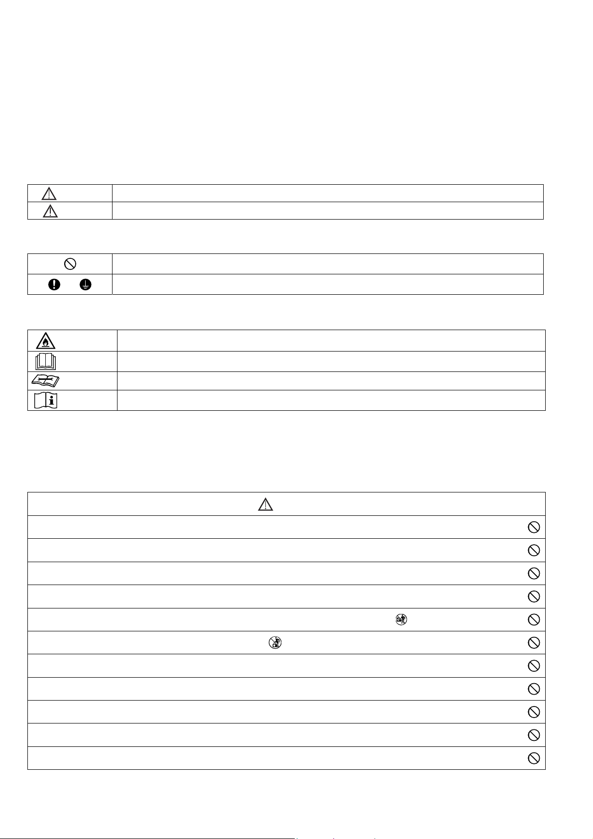
meaning of each indication used is as below.
Incorrect installation due to ignorance or negligence of the instructions will cause harm or damage, and the
seriousness is classified by the following indications.
Please leave this installation manual with the unit after installation.
WARNING
CAUTION
The items to be followed are classified by the symbols:
Explanation of symbols displayed on the indoor unit or outdoor unit.
WARNING
CAUTION
CAUTION This symbol shows that a service personnel should be handling this equipment with reference to the Installation Manual.
CAUTION This symbol shows that there is information included in the Operation Manual and/or Installation Manual.
Carry out test run to confirm that no abnormality occurs after the installation. Then, explain to user the operation,
care and maintenance as stated in instructions. Please remind the customer to keep the operating instructions for
future reference.
If there is any doubt about the installation procedure or operation, always contact the authorized dealer for advice
and information.
This indication shows the possibility of causing death or serious injury.
This indication shows the possibility of causing injury or damage to properties only.
Symbol with white background denotes item that is PROHIBITED.
Symbol with dark background denotes item that must be carried out.
This symbol shows that this equipment uses a flammable refrigerant. If the refrigerant is leaked, together with an
external ignition source, there is a possibility of ignition.
This symbol shows that the Installation Manual should be read carefully.
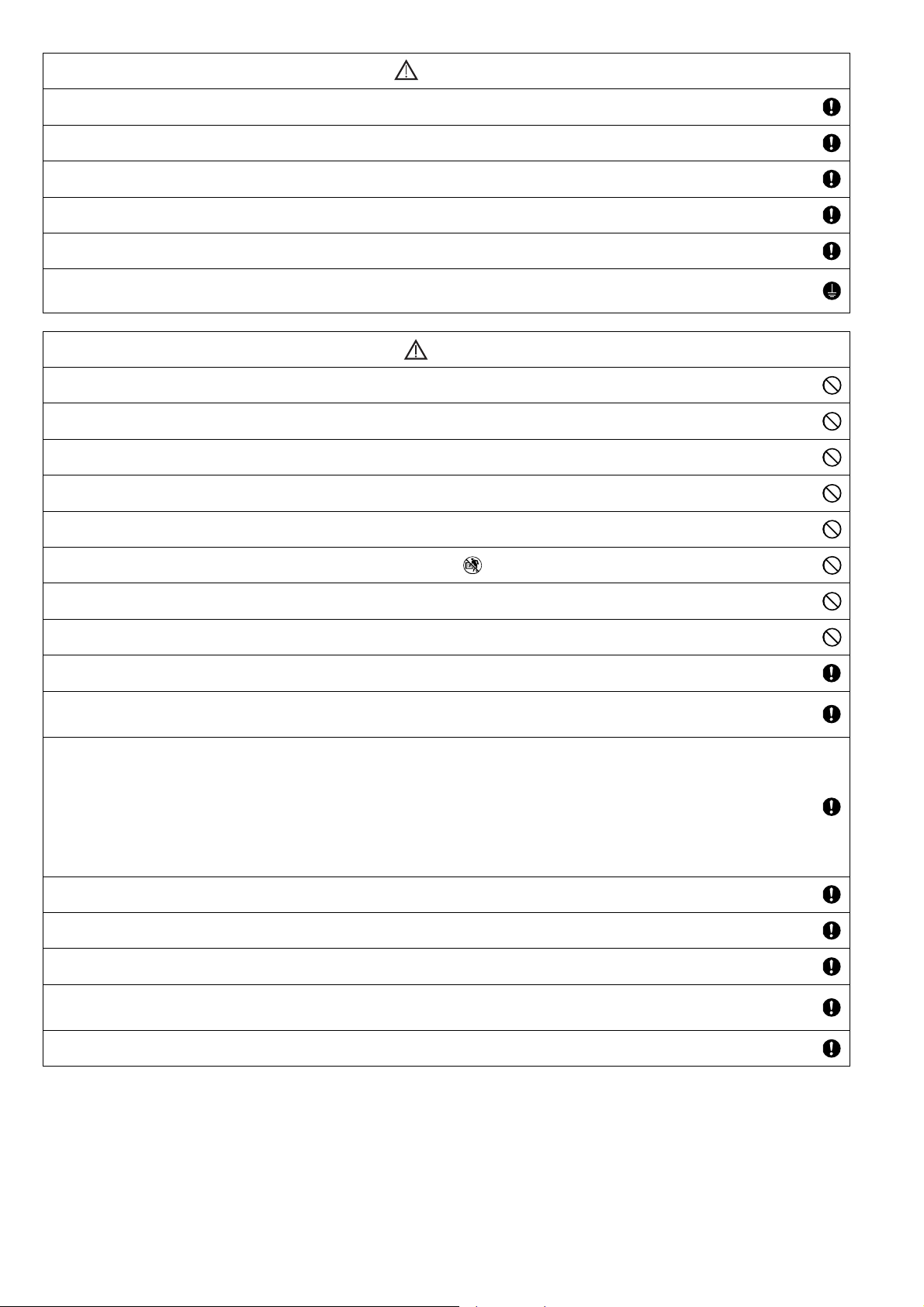
WARNING
Do not use means to accelerate the defrosting process or to clean, other than those recommended by the manufacturer. Any unfit
1.
method or using incompatible material may cause product damage, burst and serious injury.
Do not install outdoor unit near handrail of veranda. When installing outdoor unit at veranda of high rise building, child may climb up to
2.
outdoor unit and cross over the handrail and causing accident.
Do not use unspecified cord, modified cord, joint cord or extension cord for power supply cord. Do not share the single outlet with
3.
other electrical appliances. Poor contact, poor insulation or over current will cause electrical shock or fire.
4. Do not tie up the power supply cord into a bundle by band. Abnormal temperature rise on power supply cord may happen.
5. Do not insert your fingers or other objects into the unit, high speed rotating fan may cause injury.
6. Do not sit or step on the unit, you may fall down accidentally.
7. Keep plastic bag (packaging material) away from small children, it may cling to nose and mouth and prevent breathing.
When install or relocate outdoor unit, do not let any substance other than the specified refrigerant, e.g. air etc. mix into refrigerant
8.
cycle (piping). Mixing of air etc. will cause abnormal high pressure in refrigeration cycle and result in explosion, injury etc.
9. Do not use pipe wrench to install refrigerant piping. It might deform the piping and cause the unit to malfunction.
10. Do not purchase unauthorized electrical parts for installation, service, maintenance and etc.. They might cause electrical shock or fire.
Do not modify the wiring of outdoor unit for installation of other components (i.e. heater, etc). Overloaded wiring or wire connection
11.
points may cause electrical shock or fire.
4

WARNING
r
Do not pierce or burn as the appliance is pressurized. Do not expose the appliance to heat, flame, sparks, or other sources of ignition.
12.
Else, it may explode and cause injury or death.
13. Do not add or replace refrigerant other than specified type. It may cause product damage, burst and injury etc.
Do not place containers with liquids on top of the Tank Unit. It may cause Tank Unit damage and/or fire could occurs if they leak or
14.
spill onto the Tank Unit.
Do not use joint cable for Tank Unit / Outdoor Unit connection cable. Use specified Tank Unit / Outdoor Unit connection cable, refer to
instruction
15.
cable so that no external force will be acted on the terminal. If connection or fixing is not perfect, it will cause heat up or fire at the
connection.
For electrical work, follow the local wiring standard, national regulation, legislation and this installation instructions. An independent
16.
circuit and single outlet must be used. If electrical circuit capacity is not enough or defect found in the electrical work, it will cause
electrical shock or fi
Engage authorized dealer or specialist for installation. If installation done by the user is incorrect / defective, it will cause water
17.
leakage, electrical shock or fire.
For water circuit installation work, follow to relevant European and national regulations (including EN61770) and local plumbing and
18.
building regulation codes.
This is a R32 model, use piping, flare nut and tools which is specified for R32 refrigerant. Using of existing (R22) piping, flare nut
and tools may cause abnormally high pressure in the refrigerant cycle (piping), and possibly result in explosion and injury.
19.
Thickness for copper pipes used with R32 must be more than 0.8 mm. Never use copper pipes thinner than 0.8 mm.
It is desirable that the amount of residual oil is less than 40 mg/10 m.
When installing or relocating Tank Unit, do not let any substance other than the specified refrigerant, eg. air etc. mix into refrigeration
20.
cycle (piping). Mixing of air etc. will cause abnormal high pressure in refrigeration cycle and result in explosion, injury etc.
For refrigeration system work, install according to this installation instructions strictly. If installation is defective, it will cause water
21.
leakage, electrical shock or fire.
Install at a strong and firm location which is able to withstand weight of the set. If the strength is not enough or installation is not
22.
properly done, the set will drop and cause injury.
Do not use joint cable for outdoor connection cable. Use specified outdoor connection cable, refer to instruction
23.
CABLE TO THE OUTDOOR UNIT and connect tightly for outdoor connection. Clamp the cable so that no external force will be acted
on the terminal. If connection or fixing is not perfect, it will cause heat up or fire at the connection.
Wire routing must be properly arranged so that control board cover is fixed properly. If control board cover is not fixed perfectly, it will
24.
cause fire or electrical shock.
This equipment is strongly recommended to be installed with Residual Current Device (RCD) on-site according to the respective
25.
national wiring rules or country-specific safety measures in terms of residual current.
During installation, install the refrigerant piping properly before running the compressor. Operation of compressor without fixing
26.
refrigeration piping and valves at opened position will cause suck-in of air, abnormal high pressure in refrigeration cycle and result in
explosion, injury etc.
During pump down operation, stop the compressor before removing the refrigeration piping. Removal of refrigeration piping while
27.
compressor is operating and valves are opened will cause suck-in of air, abnormal high pressure in refrigeration cycle and result in
explosion, injury etc.
Tighten the flare nut with torque wrench according to specified method. If the flare nut is over tightened, after a long period, the flare
28.
may break and cause refrigerant gas leakage.
After completion of installation, confirm there is no leakage of refrigerant gas. It may generate toxic gas when the refrigerant contacts
29.
with fire.
Ventilate the room if there is refrigerant gas leakage during operation. Extinguish all fire sources if present. It may cause toxic gas
30.
when the refrigerant contacts with fire.
Use the attached accessories parts and specified parts for installation. Otherwise, it will cause the set to fall, water leakage, fire or
31.
electrical shock.
4
CONNECT THE CABLE TO THE TANK UNIT and connect tightly for Tank Unit / Outdoor Unit connection. Clamp the
e.
5
CONNECT THE
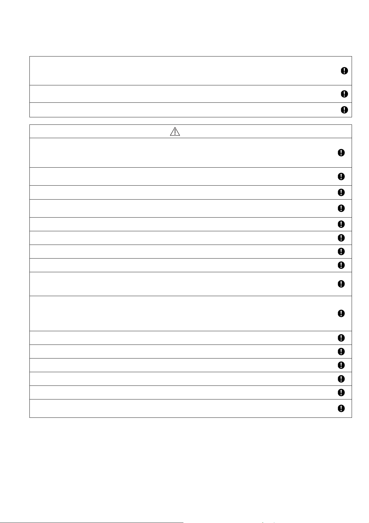
32. Only use the supplied or specified installation parts. Else, it may causes unit vibrate, fall, water leakage, electrical shock or fire.
33. If there is any doubt about the installation procedure or operation, always contact the authorized dealer for advice and information.
34. Select a location where in case of water leakage, the leakage will not cause damage to other properties
When installing electrical equipment at wooden building of metal lath or wire lath, in accordance with electrical facility standard, no
35.
electrical contact between equipment and building is allowed. Insulator must be installed in between.
Any work carried out on the Tank Unit / Outdoor Unit after removing any panels which is secured by screws, must be carried out under
36.
the supervision of authorized dealer and licensed installation contractor.
37. This system is multi supply appliance. All circuits must be disconnected before accessing the unit terminals.
For cold water supply has a backflow regulator, check valve or water meter with check valve, provisions for thermal expansion of
38.
water in the hot water system must be provided. Otherwise it will cause water leakage.
5
WARNING
The piping installation work must be flushed before Tank Unit is connected to remove contaminants. Contaminants may damage the
39.
Tank Unit components.
This installation may be subjected to building regulation approval applicable to respective country that may require to notify the local
40.
authority before installation.
The Tank Unit must be shipped and stored in upright condition and dry environment. It may laid on its back when being moved into the
41.
building.
Work done to the Tank Unit after remove the front plate cover that secured by screws, must be carried out under the supervision of
42.
authorized dealer, licensed installation contractor, skilled person and instructed person.
43. Be aware that refrigerants may not contain an odour.
This unit must be properly earthed. The electrical earth must not be connected to a gas pipe, water pipe, the earth of lightening rod or
44.
a telephone. Otherwise there is a danger of electrical shock in the event of an insulation breakdown or electrical earth fault in the
outdoor unit.
CAUTION
Do not install the Tank Unit / Outdoor Unit at place where leakage of flammable gas may occur. In case gas leaks and accumulates at
1.
surrounding of the unit, it may cause fire.
2. Prevent liquid or vapor from entering sumps or sewers since vapor is heavier than air and may form suffocating atmospheres.
Do not release refrigerant during piping work for installation, re-installation and during repairing a refrigeration parts. Take care of the
3.
liquid refrigerant, it may cause frostbite.
4. Do not install this appliance in a laundry room or other high humidity location. This condition will cause rust and damage to the unit.
Make sure the insulation of power supply cord does not contact hot part (i.e. refrigerant piping, water piping) to prevent from insulation
5.
failure (melt).
6. Do not touch the sharp aluminium fin, sharp parts may cause injury.
Do not apply excessive force to water pipes that may damage the pipes. If water leakage occurs, it will cause flooding and damage to
7.
other properties.
8. Do not transport the Tank Unit with water inside the unit. It may cause damage to the unit.
Carry out drainage piping as mentioned in installation instructions. If drainage is not perfect, water may enter the room and damage
9.
the furniture.
Select an installation location which is easy for maintenance.
10.
Incorrect installation, service or repair of this Tank Unit / Outdoor Unit may increase the risk of rupture and this may result in loss
damage or injury and/or property.
Power supply connection to Tank Unit.
Power supply point should be in easily accessible place for power disconnection in case of emergency.
Must follow local national wiring standard, regulation and this installation instruction.
Strongly recommended to make permanent connection to a circuit breaker.
11.
- Power Supply 1: For WH-UD03JE5 and WH-UD05JE5, use approved 15/16A 2-poles circuit breaker with a minimum contact gap
of 3.0mm.
For WH-UD07JE5 and WH-UD09JE5, use approved 25A 2-poles circuit breaker with a minimum contact gap of
3.0mm.
- Power Supply 2: Use approved 16A 2-poles circuit breaker with a minimum contact gap of 3.0mm.
12. Ensure the correct polarity is maintained throughout all wiring. Otherwise, it will cause electrical shock or fire.
After installation, check the water leakage condition in connection area during test run. If leakage occurs, it will cause damage to other
13.
properties.
14. If the Tank Unit not operates for long time, the water inside the Tank Unit should be drained.
Installation work.
15.
It may need three or more people to carry out the installation work. The weight of Tank Unit / Outdoor Unit might cause injury if carried
by one person.
16. Keep any required ventilation openings clear of obstruction.
6
2. Precaution For Using R32 Refrigerant
r
The basic installation work procedures are the same as conventional refrigerant (R410A, R22) models.
However, pay careful attention to the following points:
When connecting flare at indoor side, make sure that the flare connection is used only once, if torqued up and released, the flare must
be remade. Once the flare connection was torqued up correctly and leak test was made, thoroughly clean and dry the surface to
1.
remove oil, dirt and grease by following instructions of silicone sealant. Apply neutral cure (Alkoxy type) & ammonia-free silicone
sealant that is non-corrosive to copper & brass to the external of the flared connection to prevent the ingress of moisture on both the
gas & liquid sides. (Moisture may cause freezing and premature failure of the connection)
The appliance shall be stored, installed and operated in a well ventilated room with comply to Indoor Floor Area Requirement and
2.
without any continuously operating ignition source. Keep away from open flames, any operating gas appliances or any operating
electric heater. Else, it may explode and cause injury or death.
Refer to “PRECAUTION FOR USING R32 REFRIGERANT” in outdoor unit installation manual for other precautions that need to pay
3.
attention to.
WARNING
Since the working pressure is higher than that of refrigerant R22 models, some of the piping and installation and service tools
are special.
1.
Especially, when replacing a refrigerant R22 model with a new refrigerant R32 model, always replace the conventional piping
and flare nuts with the R32 and R410A piping and flare nuts on the outdoor unit side.
For R32 and R410A, the same flare nut on the outdoor unit side and pipe can be used.
The mixing of different refrigerants within a system is prohibited. Models that use refrigerant R32 and R410A have a different
2.
charging port thread diameter to prevent erroneous charging with refrigerant R22 and for safety.
e, check beforehand. [The charging port thread diameter for R32 and R410A is 12.7 mm (1/2 inch).]
Therefo
Ensure that foreign matter (oil, water, etc.) does not enter the piping.
3.
Also, when storing the piping, securely seal the opening by pinching, taping, etc. (Handling of R32 is similar to R410A.)
Operation, maintenance, repairing and refrigerant recovery should be carried out by trained and certified personnel in the use of
4.
flammable refrigerants and as recommended by the manufacturer. Any personnel conducting an operation, servicing or
maintenance on a system or associated parts of the equipment should be trained and certified.
Any part of refrigerating circuit (evaporators, air coolers, AHU, condensers or liquid receivers) or piping should not be located in
5.
the proximity of heat sources, open flames, operating gas appliance or an operating electric heater.
The user/owner or their authorized representative shall regularly check the alarms, mechanical ventilation and detectors, at
6.
least once a year, where as required by national regulations, to ensure their correct functioning.
7. A logbook shall be maintained. The results of these checks shall be recorded in the logbook.
8. In case of ventilations in occupied spaces shall be checked to confirm no obstruction.
Before a new refrigerating system is put into service, the person responsible for placing the system in operation should ensure
that trained and certified operating personnel are instructed on the basis of the instruction manual about the construction,
9.
supervision, operation and maintenance of the refrigerating system, as well as the safety measures to be observed, and the
properties and handling of the refrigerant used.
The general requirement of trained and certified personnel are indicated as below:
a) Knowledge of legislation, regulations and standards relating to flammable refrigerants; and,
b) Detailed knowledge of and skills in handling flammable refrigerants, personal protective equipment, refrigerant leakage
10.
11.
prevention, handling of cylinders, charging, leak detection, recovery and disposal; and,
c) Able to understand and to apply in practice the requirements in the national legislation, regulations and Standards; and,
d) Continuously undergo regular and further training to maintain this expertise.
Air-to-Water Heatpump piping in the occupied space shall be installed in such a way to protect against accidental damage in
operation and service.
12. Precautions shall be taken to avoid excessive vibration or pulsation to refrigerating piping.
Ensure protection devices, refrigerating piping and fittings are well protected against adverse environmental effects (such as the
13.
danger of water collecting and freezing in relief pipes or the accumulation of dirt and debris).
Expansion and contraction of long runs piping in refrigerating systems shall be designed and installed securely (mounted and
14.
guarded) to minimize the likelihood hydraulic shock damaging the system.
15. Protect the refrigerating system from accidental rupture due to moving furniture or reconstruction activities.
To ensure no leaking, field-made refrigerant joints indoors shall be tightness tested. The test method shall have a sensitivity of 5
16.
grams per year of refrigerant or better under a pressure of at least 0,25 times the maximum allowable pressure (>1.04MPa, max
4.15MPa). No leak shall be detected.
7
Installation (Space)
Must ensure the installation of pipe-work shall be kept to a minimum. Avoid use dented pipe and do not allow acute
bending.
Must ensure that pipe-work shall be protected from physical damage.
Must comply with national gas regulations, state municipal rules and legislation. Notify relevant authorities in accordance
1.
2.
with all applicable regulations.
Must ensure mechanical connections be accessible for maintenance purposes.
In cases that require mechanical ventilation, ventilation openings shall be kept clear of obstruction.
When disposal of the product, do follow to the precautions in #12 and comply with national regulations.
In case of field charge, the effect on refrigerant charge caused by the different pipe length has to be quantified, measured
and labelled.
Always contact to local municipal offices for proper handling.
Servicing
2-1. Service personnel
Any qualified person who is involved with working on or breaking into a refrigerant circuit should hold a current valid
certificate from an industry-accredited assessment authority, which authorizes their competence to handle refrigerants
safely in accordance with an industry recognized assessment specification.
Servicing shall only be performed as recommended by the equipment manufacturer. Maintenance and repair requiring the
assistance of other skilled personnel shall be carried out under the supervision of the person competent in the use of
flammable refrigerants.
Servicing shall be performed only as recommended by the manufacturer.
The system is inspected, regularly supervised and maintained by a trained and certified service personnel who is employed
by the person user or party responsible.
Ensure the actual refrigerant charge is in accordance with the room size within which the refrigerant containing parts are
installed.
Ensure refrigerant charge not to leak.
2-2. Work
Prior to beginning work on systems containing flammable refrigerants, safety checks are necessary to ensure that the risk
of ignition is minimised.
For repair to the refrigerating system, the precautions in #2-2 to #2-8 must be followed before conducting work on the
system.
Work shall be undertaken under a controlled procedure so as to minimize the risk of a flammable gas or vapour being
present while the work is being performed.
All maintenance staff and others working in the local area shall be instructed and supervised on the nature of work being
carried out.
Avoid working in confined spaces. Always ensure away from source, at least 2 meter of safety distance, or zoning of free
space area of at least 2 meter in radius.
Wear appropriate protective equipment, including respiratory protection, as conditions warrant.
Keep all sources of ignition and hot metal surfaces away.
2-3. Checking for presence of refrigerant
The area shall be checked with an appropriate refrigerant detector prior to and during work, to ensure the technician is
aware of potentially flammable atmospheres.
Ensure that the leak detection equipment being used is suitable for use with flammable refrigerants, i.e. non sparking,
adequately sealed or intrinsically safe.
In case of leakage/spillage happened, immediately ventilate area and stay upwind and away from spill/release.
In case of leakage/spillage happened, do notify persons down wind of the leaking/spill, isolate immediate hazard area and
keep unauthorized personnel out.
2-4. Presence of fire extinguisher
If any hot work is to be conducted on the refrigerating equipment or any associated parts, appropriate fire extinguishing
equipment shall be available at hand.
Have a dry powder or CO
2-5. No ignition sources
No person carrying out work in relation to a refrigerating system which involves exposing any pipe work that contains or
has contained flammable refrigerant shall use any sources of ignition in such a manner that it may lead to the risk of fire or
explosion. He/She must not be smoking when carrying out such work.
All possible ignition sources, including cigarette smoking, should be kept sufficiently far away from the site of installation,
repairing, removing and disposal, during which flammable refrigerant can possibly be released to the surrounding space.
Prior to work taking place, the area around the equipment is to be surveyed to make sure that there are no flammable
hazards or ignition risks.
“No Smoking” signs shall be displayed.
2-6. Ventilated area
Ensure that the area is in the open or that it is adequately ventilated before breaking into the system or conducting any hot
work.
A degree of ventilation shall continue during the period that the work is carried out.
The ventilation should safely disperse any released refrigerant and preferably expel it externally into the atmosphere.
CAUTION
fire extinguisher adjacent to the charging area.
2
8
CAUTION
r
2-7. Checks to the refrigerating equipment
Where electrical components are being changed, they shall be fit for the purpose and to the correct specification.
At all times the manufacturer’s maintenance and service guidelines shall be followed.
If in doubt consult the manufacturer’s technical department for assistance.
The following checks shall be applied to installations using flammable refrigerants.
- The actual refrigerant charge is in accordance with the room size within which the refrigerant containing parts are installed.
- The ventilation machinery and outlets are operating adequately and are not obstructed.
- If an indirect refrigerating circuit is being used, the secondary circuit shall be checked for the presence of refrigerant.
- Marking to the equipment continues to be visible and legible. Markings and signs that are illegible shall be corrected.
- Refrigerating pipe or components are installed in a position where they are unlikely to be exposed to any substance
which may corrode refrigerant containing components, unless the components are constructed of materials which are
inherently resistant to being corroded or are properly protected against being so corroded.
2-8. Checks to electrical devices
2.
Repair and maintenance to electrical components shall include initial safety checks and component inspection procedures.
Initial safety checks shall include but not limit to:-
- That capacitors are discharged: this shall be done in a safe manner to avoid possibility of sparking.
- That there is no live electrical components and wiring are exposed while charging, recovering or purging the system.
- That there is continuity of earth bonding.
At all times the manufacturer’s maintenance and service guidelines shall be followed.
If in doubt consult the manufacturer’s technical department for assistance.
If a fault exists that could compromise safety, then no electrical supply shall be connected to the circuit until it is
satisfactorily dealt with.
If the fault cannot be corrected immediately but it is necessary to continue operation, an adequate temporary solution shall
be used.
The owner of the equipment must be informed o
Repairs to sealed components
During repairs to sealed components, all electrical supplies shall be disconnected from the equipment being worked upon
3.
4.
5.
6.
prior to any removal of sealed covers, etc.
If it is absolutely necessary to have an electrical supply to equipment during servicing, then a permanently operating form
of leak detection shall be located at the most critical point to warn of a potentially hazardous situation.
Particular attention shall be paid to the following to ensure that by working on electrical components, the casing is not
altered in such a way that the level of protection is affected. This shall include damage to cables, excessive number of
connections, terminals not made to original specification, damage to seals, incorrect fitting of glands, etc.
Ensure that apparatus is mounted securely.
Ensure that seals or sealing materials have not degraded such that they no longer serve the purpose of preventing the
ingress of flammable atmospheres.
Replacement parts shall be in accordance with the manufacturer’s specifications.
NOTE:
Repair to intrinsically safe components
Do not apply any permanent inductive or capacitance loads to the circuit without ensuring that this will not exceed the
permissible voltage and current permitted for the equipment in use.
Intrinsically safe components are the only types that can be worked on while live in the presence of a flammable
atmosphere.
The test apparatus shall be at the correct rating.
Replace components only with parts specified by the manufacturer. Unspecified parts by manufacturer may result ignition
of refrigerant in the atmosphere from a leak.
Cabling
Check that cabling will not be subject to wear, corrosion, excessive pressure, vibration, sharp edges or any other adverse
environmental effects.
The check shall also take into account the effects of aging or continual vibration from sources such as compressors or
fans.
Detection of flammable refrigerants
Under no circumstances shall potential sources of ignition be used in the searching or detection of refrigerant leaks.
A halide torch (or any other detector using a naked flame) shall not be used.
The use of silicon sealant may inhibit the effectiveness of some types of leak detection equipment.
Intrinsically safe components do not have to be isolated prior to working on them.
reported so all parties are advised thereinafter.
9
CAUTION
The following leak detection methods are deemed acceptable for all refrigerant systems.
No leaks shall be detected when using detection equipment with a sensitivity of 5 grams per year of refrigerant or better
under a pressure of at least 0,25 times the maximum allowable pressure (>1.04MPa, max 4.15MPa). For example, a
universal sniffer.
Electronic leak detectors may be used to detect flammable refrigerants, but the sensitivity may not be adequate, or may
need re-calibration.
(Detection equipment shall be calibrated in a refrigerant-free area.)
Ensure that the detector is not a potential source of ignition and is suitable for the refrigerant used.
7.
Leak detection equipment shall be set at a percentage of the LFL of the refrigerant and shall be calibrated to the refrigerant
employed and the appropriate percentage of gas (25 % maximum) is confirmed.
Leak detection fluids are also suitable for use with most refrigerants, for example, bubble method and fluorescent method
agents. The use of detergents containing chlorine shall be avoided as the chlorine may react with the refrigerant and
corrode the copper pipe-work.
If a leak is suspected, all naked flames shall be removed/extinguished.
If a leakage of refrigerant is found which requires brazing, all of the refrigerant shall be recovered from the system, or
isolated (by means of shut off valves) in a part of the system remote from the leak.
The precautions in #8 must be followed to remove the refrigerant.
Removal and evacuation
When breaking into the refrigerant circuit to make repairs – or for any other purpose – conventional procedures shall be
used.
However, it is important that best practice is followed since flammability is a consideration.
The following procedure shall be adhered to:
• remove refrigerant -> • purge the circuit with inert gas -> • evacuate -> • purge with inert gas ->
• open the circuit by cutting or brazing
The refrigerant charge shall be recovered into the correct recovery cylinders.
8.
The system shall be purged with OFN to render the appliance safe. (remark: OFN = oxygen free nitrogen, type of inert gas)
This process may need to be repeated several times.
Compressed air or oxygen shall not be used for this task.
Purging shall be achieved by breaking the vacuum in the system with OFN and continuing to fill until the working pressure
is achieved, then venting to atmosphere, and finally pulling down to a vacuum.
This process shall be repeated until no refrigerant is within the system.
When the final OFN charge is used, the system shall be vented down to atmospheric pressure to enable work to take
place.
This operation is absolutely vital if brazing operations on the pipe work are to take place.
Ensure that the outlet for the vacuum pump is not close to any potential ignition sources and there is ventilation available.
Charging procedures
In addition to conventional charging procedures, the following requirements shall be followed.
9.
- Ensure that contamination of different refrigerants does not occur when using charging equipment.
- Hoses or lines shall be as short as possible to minimize the amount of refrigerant contained in them.
- Cylinders shall be kept in an appropriate position according to the instructions.
- Ensure that the refrigerating system is earthed prior to charging the system with refrigerant.
- Label the system when charging is complete (if not already).
- Extreme care shall be taken not to over fill the refrigerating system.
Prior to recharging the system it shall be pressure tested with OFN (refer to #7).
The system shall be leak tested on completion of charging but prior to commissioning.
A follow up leak test shall be carried out prior to leaving the site.
Electrostatic charge may accumulate and create a hazardous condition when charging and discharging the refrigerant.
To avoid fire or explosion, dissipate static electricity during transfer by grounding and bonding containers and equipment
before charging/discharging.
10
CAUTION
Decommissioning
Before carrying out this procedure, it is essential that the technician is completely familiar with the equipment and all its
details.
It is recommended good practice that all refrigerants are recovered safely.
Prior to the task being carried out, an oil and refrigerant sample shall be taken in case analysis is required prior to re-use of
recovered refrigerant.
It is essential that electrical power is available before the task is commenced.
a)
Become familiar with the equipment and its operation.
Isolate system electrically.
b)
Before attempting the procedure ensure that:
c)
• mechanical handling equipment is available, if required, for handling refrigerant cylinders;
• all personal protective equipment is available and being used correctly;
10.
• the recovery process is supervised at all times by a competent person;
• recovery equipment and cylinders conform to the appropriate standards.
Pump down refrigerant system, if possible.
d)
If a vacuum is not possible, make a manifold so that refrigerant can be removed from various parts of the system.
e)
Make sure that cylinder is situated on the scales before recovery takes place.
f)
Start the recovery machine and operate in accordance with instructions.
g)
Do not over fill cylinders. (No more than 80 % volume liquid charge).
h)
Do not exceed the maximum working pressure of the cylinder, even temporarily.
i)
When the cylinders have been filled correctly and the process completed, make sure that the cylinders and the
j)
equipment are removed from site promptly and all isolation valves on the equipment are closed off.
Recovered refrigerant shall not be charged into another refrigerating system unless it has been cleaned and checked.
k)
Electrostatic charge may accumulate and create a hazardous condition when charging or discharging the refrigerant.
To avoid fire or explosion, dissipate static electricity during transfer by grounding and bonding containers and equipment
before charging/discharging.
Labelling
Equipment shall be labelled stating that it has been de-commissioned and emptied of refrigerant.
11.
The label shall be dated and signed.
Ensure that there are labels on the equipment stating the equipment contains flammable refrigerant.
Recovery
When removing refrigerant from a system, either for servicing or decommissioning, it is recommended good practice that
all refrigerants are removed safely.
When transferring refrigerant into cylinders, ensure that only appropriate refrigerant recovery cylinders are employed.
Ensure that the correct number of cylinders for holding the total system charge are available.
All cylinders to be used are designated for the recovered refrigerant and labelled for that refrigerant (i.e. special cylinders
for the recovery of refrigerant).
Cylinders shall be complete with pressure relief valve and associated shut-off valves in good working order.
Recovery cylinders are evacuated and, if possible, cooled before recovery occurs.
The recovery equipment shall be in good working order with a set of instructions concerning the equipment that is at hand
and shall be suitable for the recovery of flammable refrigerants.
In addition, a set of calibrated weighing scales shall be available and in good working order.
12.
Hoses shall be complete with leak-free disconnect couplings and in good condition.
Before using the recovery machine, check that it is in satisfactory working order, has been properly maintained and that
any associated electrical components are sealed to prevent ignition in the event of a refrigerant release.
Consult manufacturer if in doubt.
The recovered refrigerant shall be returned to the refrigerant supplier in the correct recovery cylinder, and the relevant
Waste Transfer Note arranged.
Do not mix refrigerants in recovery units and especially not in cylinders.
If compressors or compressor oils are to be removed, ensure that they have been evacuated to an acceptable level to
make certain that flammable refrigerant does not remain within the lubricant.
The evacuation process shall be carried out prior to returning the compressor to the suppliers.
Only electric heating to the compressor body shall be employed to accelerate this process.
When oil is drained from a system, it shall be carried out safely.
11
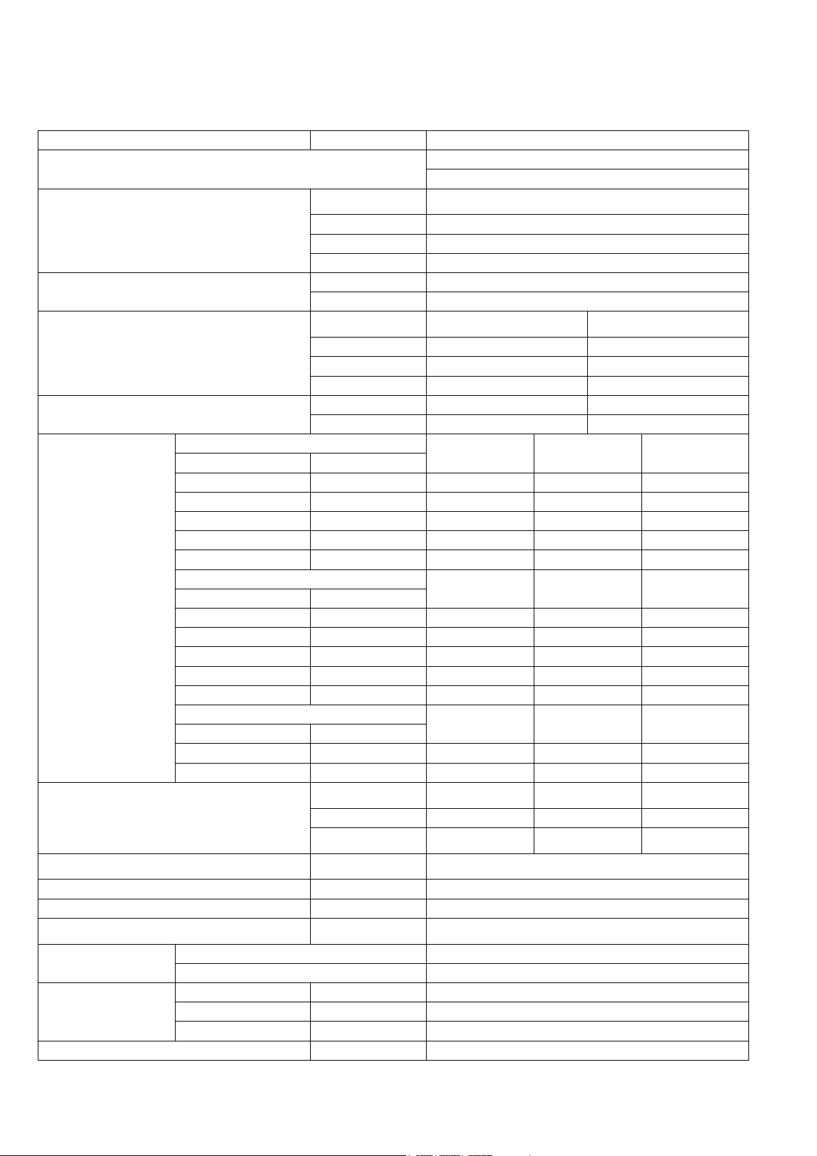
3. Specifications
/
3.1 WH-ADC0309J3E5UK WH-UD03JE5
Item Unit Outdoor Unit
Performance Test Condition
Condition
(Ambient
Cooling Capacity
Cooling EER
(Ambient/Water)
Heating Capacity
Heating COP
Low Temperature Application (W35)
Application Climate
Pdesign kW 4.0 4.0 3.0
Tbivalent/TOL °C 2 / 2 -10 / -10 -20 / -22
SCOP/ns (W/W)/% 6.20 / 245 5.07 / 200 4.00 / 157
Annual Consumption kWh 862 1631 1848
Class A++ A++ A++
Medium Temperature Application (W55)
Heating Erp
Noise Level
Air Flow m3/min (ft3/min)
Refrigeration Control Device Expansion Valve
Refrigeration Oil cm3 FW50S (450)
Refrigerant kg (oz)
F-GAS
Dimension
Net Weight kg (lbs) 37 (82)
Application Climate
Pdesign kW 4.0 3.0 2.0
Tbivalent/TOL °C 2 / 2 -10 / -10 -20 / -22
SCOP/ns (W/W)/% 4.20 / 165 3.47 / 136 2.83 / 110
Annual Consumption kWh 1274 1788 1740
Class A++ A++ A+
DHW
Application Climate
COP/nwh (W/W)/% 3.88 / 155 3.30 / 132 2.48 / 99
AEC kWh 640 760 994
(Ambient/Water)
Power Level dB Cooling: 61***
GWP 675
CO2eq (ton) (Precharged/Maximum) 0.608 / 0.810
Height mm (inch) 622 (24-1/2)
Width mm (inch) 824 (32-15/32)
Depth mm (inch) 298 (11-24/32)
Water)
kW 3.20
BTU/h 10900
kcal/h 2750
W/W 3.52
kcal/hW 3.02
Condition
kW 3.20 3.20
BTU/h 10900 10900
kcal/h 2750 2750
W/W 5.33 3.64
kcal/hW 4.58 3.13
Condition
dB (A) Cooling: 45*** Heating: 44*** —
A7W35 A2W35
Warmer Average Colder
Warmer Average Colder
Warmer Average Colder
A35W7 A7W35 A2W35
R32, 0.90 (31.8) (Pre-charged)
R32, 1.20 (42.4) (Maximum)
EN 14511
EN 14825
A35W7
Heating: 60***
Heating: 55****
Cooling: 33.9 (1200)
Heating: 28.9 (1020)
—
12

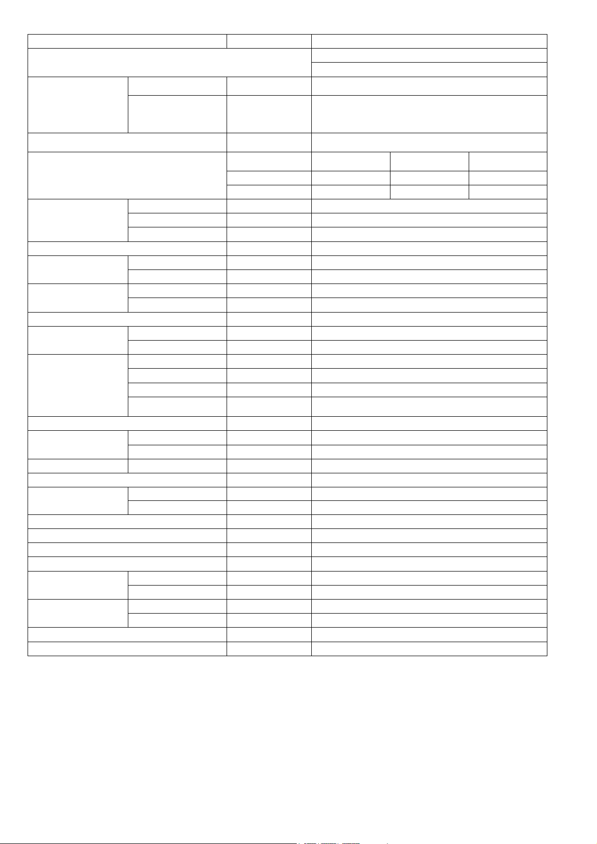
Item Unit Outdoor Unit
/
/
Pipe Diameter
Standard Length m (ft) 7 (23.0)
Pipe Length Range m (ft) 3 (9.8) ~ 25 (82.0)
I/D & O/D Height Difference m (ft) 20 (65.6)
Additional Gas Amount g/m (oz/ft) 20 (0.2)
Refrigeration Charge Less m (ft) 10 (32.8)
Compressor
Fan
Heat Exchanger
Power Source (Phase, Voltage, Cycle)
Input Power
Maximum Input Power For Heatpump System kW 2.59
Power Supply 1 : Phase (Ø) / Max. Current (A) / Max. Input Power (W) 1Ø / 12.0 / 2.59k
Power Supply 2 : Phase (Ø) / Max. Current (A) / Max. Input Power (W) 1Ø / 13.0 / 3.00k
Power Supply 3 : Phase (Ø) / Max. Current (A) / Max. Input Power (W) — / — / —
Starting Current A 2.9
Running Current
Maximum Current For Heatpump System A 12.0
Power Factor
Power factor means total figure of compressor and
outdoor fan motor.
Power Cord
Thermostat Electronic Control
Protection Device Electronic Control
Liquid mm (inch) 6.35 (1/4)
Gas mm (inch) 12.70 (1/2)
Type Hermetic Motor
Motor Type Brushless (6-poles)
Rated Output kW 0.90
Type Propeller Fan
Material PP
Motor Type DC (8-poles)
Input Power W 20 (Heating) / 23 (Cooling)
Output Power W 40
Fan Speed rpm
Fin material Aluminium (Pre Coat)
Fin Type Corrugated Fin
Row × Stage × FPI 2 × 28 × 19
Size (W × H × L) mm 36.4 × 588 × 827.7 : 856.3
Ø Single
V 230
Hz 50
Condition
(Ambient/Water)
kW Cooling: 0.91 Heating: 0.60 Heating: 0.88
Condition
(Ambient
(Ambient
Number of core -
Length m (ft) -
Water)
A Cooling: 4.3 Heating: 2.9 Heating: 4.2
Condition
Water)
% Cooling: 92 Heating: 90 Heating: 91
A35W7 A7W35 A2W35
A35W7 A7W35 A2W35
A35W7 A7W35 A2W35
Cooling: 840
Heating: 720
13
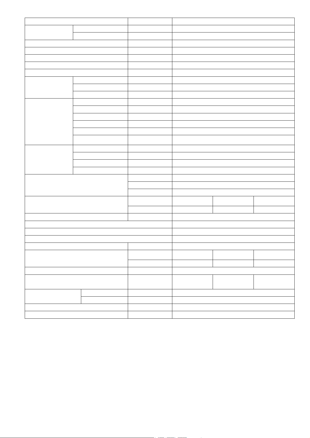
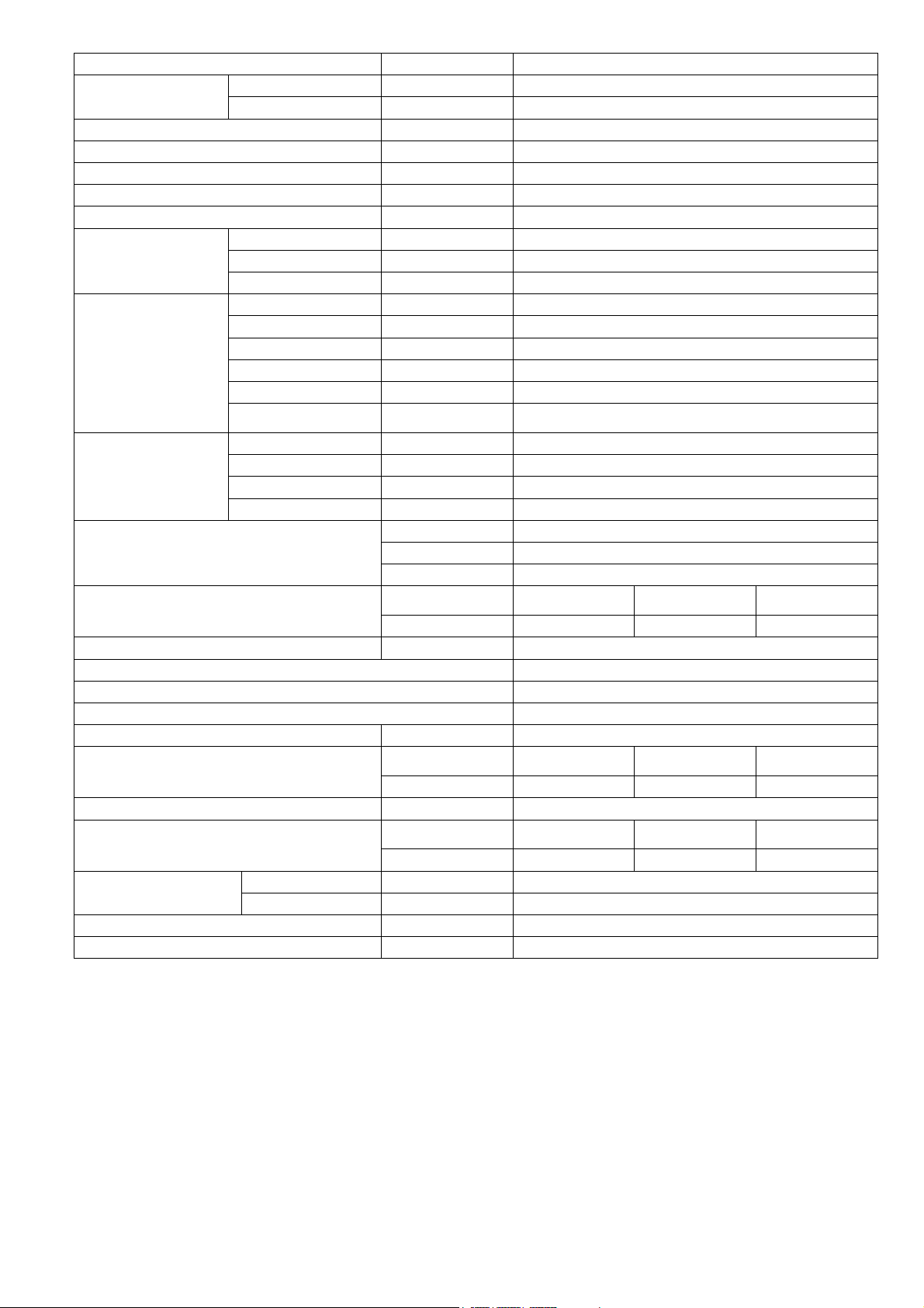
Item Unit Indoor Unit
Performance Test Condition
Outdoor Ambient °C (min./max.)
Operation Range
Internal Pressure Differential kPa
Noise Level
Dimension
Net Weight kg (lbs) 122 (269)
Refrigerant Pipe Diameter
Water Pipe Diameter
Water Drain Hose Inner Diameter mm (inch) 15.00 (19/32)
Pump
Hot Water Coil
Pressure Relief Valve Water Circuit kPa Open: 300, Close: 210 and below
Flow Switch
Pressure Release Valve kPa Open: 1000±200, Close: 700 and below
Protection Device A Earth Leakage Circuit Breaker (30 ~ 40)
Expansion Vessel
Capacity of Integrated Electric Heater / OLP TEMP kW/°C 3.00 / 80
Tank Volume (Spec / Nett) L 200 / 185
Max. Tank Water Set Temperature °C 65
Tank Coil Surface m2 1.8
Maximum Working
Pressure
Operating Pressure
Expansion Vessel Pre-charge Pressure (DHW Circuit) Bar 3.5
Pressure Reducing Valve Set Pressure (DHW Circuit) Bar 3.5
Water Outlet °C (min./max.)
Condition
(Ambient/Water)
dB (A) Cooling: 28*** Heating: 28*** —
Power Level dB Cooling: 41*** Heating: 41*** —
Depth mm (inch) 717 (28-7/32)
Width mm (inch) 598 (23-17/32)
Height mm (inch) 1800 (70-27/32)
Liquid mm (inch) 6.35 (1/4)
Gas mm (inch) 15.88 (5/8)
Room mm (inch) 31 (1-1/4)
Shower mm (inch) 19 (3/4)
Motor Type DC Motor
Input Power W 34
Type Brazed Plate
No. of Plates 36
Size (W x H x L) mm 68 × 333 × 121
Water Flow Rate l/min (m3/h)
Type VVX20 [Electronic pulse]
Measuring range l/min 5 ~ 60
Volume I 10
MWP bar 3
Heat/Cool Bar 3.0
Tank Circuit Bar 10.0
Tank Unit Bar 3.5
Expansion Relief Valve Bar 8.0
Heating (Circuit): 20 / 55 (Below Ambient -15 °C) **
Heating (Circuit): 20 / 60 (Above Ambient -10 °C) **
A35W7 A7W35 A2W35
EN 14511
EN 14825
Cooling: 10 / 43
Heating: -20 / 35
Cooling: 5 / 20
Heating (Tank): - / 65*,
Cooling: 5.0
Heating: 5.0
Cooling: 9.2 (0.6)
Heating: 9.2 (0.6)
14

Item Unit Indoor Unit
Material EN-1.4521
Pressure Vessel
Heat Exchanger
Volume L 185
Design Pressure Bar 10
Material EN-1.4521
Diameter mm 22
Thickness mm 0.8
Surface Area m2 1.8
Total Length m 25
Note:
Cooling capacities are based on outdoor air temperature of 35°C Dry Bulb with controlled indoor water inlet
temperature of 12°C and water outlet temperature of 7°C.
Heating capacities are based on outdoor air temperature of 7°C Dry Bulb (44.6°F Dry Bulb), 6°C Wet Bulb
(42.8°F Wet Bulb) with controlled indoor water inlet temperature of 30°C and water outlet temperature of 35°C.
Specifications are subjected to change without prior notice for further improvement.
* Above 55°C, only possible with backup heater operation.
** Between outdoor ambient -10 °C and -15 °C, the water outlet temperature gradually decreases from 60 °C to
55 °C.
*** The sound pressure and sound power level is measured with distance 1.0m from the unit and height at 1.5m.
(Test carry out for cooling at ambient 35°C DB and Water Out 7°C, heating at ambient 7°C DB / 6°C WB and
water out 55°C)
**** The sound power level is measured with accordance to EN12102 under conditions of the EN14825.
15

3.2 WH-ADC0309J3E5UK WH-UD05JE5
Item Unit Outdoor Unit
Performance Test Condition
Condition
(Ambient/Water)
Cooling Capacity
Cooling EER
Heating Capacity
Heating COP
Low Temperature Application (W35)
Application Climate
Pdesign kW 4.0 5.0 3.0
Tbivalent/TOL °C 2 / 2 -10 / -10 -20 / -22
SCOP/ns (W/W)/% 6.20 / 245 5.07 / 200 4.00 / 157
Annual Consumption kWh 862 2038 1848
Class A++ A++ A++
Medium Temperature Application (W55)
Heating Erp
Noise Level
Air Flow m3/min (ft3/min)
Refrigeration Control Device Expansion Valve
Refrigeration Oil cm3 FW50S (450)
Refrigerant kg (oz)
F-GAS
Dimension
Net Weight kg (lbs) 37 (82)
Application Climate
Pdesign kW 4.0 4.0 2.0
Tbivalent/TOL °C 2 / 2 -10 / -10 -20 / -22
SCOP/ns (W/W)/% 4.20 / 165 3.47 / 136 2.83 / 110
Annual Consumption kWh 1274 2385 1740
Class A++ A++ A+
DHW
Application Climate
COP/nwh (W/W)/% 3.88 / 155 3.30 / 132 2.48 / 99
AEC kWh 640 760 994
GWP 675
CO2eq (ton) (Precharged/Maximum) 0.608 / 0.810
Height mm (inch) 622 (24-1/2)
Width mm (inch) 824 (32-15/32)
Depth mm (inch) 298 (11-24/32)
kW 4.50
BTU/h 15300
kcal/h 3870
W/W 3.00
kcal/hW 2.58
Condition
(Ambient/Water)
kW 5.00 4.20
BTU/h 17100 14300
kcal/h 4300 3610
W/W 5.00 3.18
kcal/hW 4.30 2.73
Condition
(Ambient/Water)
dB (A) Cooling: 48*** Heating: 47*** —
Power Level dB Cooling: 64***
A7W35 A2W35
Warmer Average Colder
Warmer Average Colder
Warmer Average Colder
A35W7 A7W35 A2W35
R32, 0.90 (31.8) (Pre-charged)
R32, 1.20 (42.4) (Maximum)
EN 14511
EN 14825
A35W7
Heating: 64***
Heating: 55****
Cooling: 39.6 (1400)
Heating: 31.8 (1120)
—
16
Item Unit Outdoor Unit
Pipe Diameter
Standard Length m (ft) 7 (23.0)
Pipe Length Range m (ft) 3 (9.8) ~ 25 (82.0)
I/D & O/D Height Difference m (ft) 20 (65.6)
Additional Gas Amount g/m (oz/ft) 20 (0.2)
Refrigeration Charge Less m (ft) 10 (32.8)
Compressor
Fan
Heat Exchanger
Power Source (Phase, Voltage, Cycle)
Input Power
Maximum Input Power For Heatpump System kW 2.59
Power Supply 1 : Phase (Ø) / Max. Current (A) / Max. Input Power (W) 1Ø / 12.0 / 2.59k
Power Supply 2 : Phase (Ø) / Max. Current (A) / Max. Input Power (W) 1Ø / 13.0 / 3.00k
Power Supply 3 : Phase (Ø) / Max. Current (A) / Max. Input Power (W) — / — / —
Starting Current A 4.7
Running Current
Maximum Current For Heatpump System A 12.0
Power Factor
Power factor means total figure of compressor and
outdoor fan motor.
Power Cord
Thermostat Electronic Control
Protection Device Electronic Control
Liquid mm (inch) 6.35 (1/4)
Gas mm (inch) 12.70 (1/2)
Type Hermetic Motor
Motor Type Brushless (6-poles)
Rated Output kW 0.90
Type Propeller Fan
Material PP
Motor Type DC (8-poles)
Input Power W 22 (Heating) / 27 (Cooling)
Output Power W 40
Fan Speed rpm
Fin material Aluminium (Pre Coat)
Fin Type Corrugated Fin
Row × Stage × FPI 2 × 28 × 19
Size (W × H × L) mm 36.4 × 588 × 827.7 : 856.3
Ø Single
V 230
Hz 50
Condition
(Ambient/Water)
kW Cooling: 1.50 Heating: 1.00 Heating: 1.32
Condition
(Ambient/Water)
A Cooling: 6.8 Heating: 4.7 Heating: 6.1
%
Number of core -
Length m (ft) -
A35W7 A7W35 A2W35
A35W7 A7W35 A2W35
A35W7
Cooling: 96
Cooling: 980
Heating: 800
A7W35
Heating: 93
A2W35
Heating: 94
17

Item Unit Indoor Unit
Performance Test Condition
Outdoor Ambient °C (min./max.)
Operation Range
Internal Pressure Differential kPa
Noise Level
Dimension
Net Weight kg (lbs) 122 (269)
Refrigerant Pipe Diameter
Water Pipe Diameter
Water Drain Hose Inner Diameter mm (inch) 15.00 (19/32)
Pump
Hot Water Coil
Pressure Relief Valve Water Circuit kPa Open: 300, Close: 210 and below
Flow Switch
Pressure Release Valve kPa Open: 1000±200, Close: 700 and below
Protection Device A Earth Leakage Circuit Breaker (30 ~ 40)
Expansion Vessel
Capacity of Integrated Electric Heater / OLP TEMP kW/°C 3.00 / 80
Tank Volume (Spec / Nett) L 200 / 185
Max. Tank Water Set Temperature °C 65
Tank Coil Surface m2 1.8
Maximum Working
Pressure
Operating Pressure
Expansion Vessel Pre-charge Pressure (DHW Circuit) Bar 3.5
Pressure Reducing Valve Set Pressure (DHW Circuit) Bar 3.5
Water Outlet °C (min./max.)
Condition
(Ambient/Water)
dB (A) Cooling: 28*** Heating: 28*** —
Power Level dB Cooling: 41*** Heating: 41*** —
Depth mm (inch) 717 (28-7/32)
Width mm (inch) 598 (23-17/32)
Height mm (inch) 1800 (70-27/32)
Liquid mm (inch) 6.35 (1/4)
Gas mm (inch) 15.88 (5/8)
Room mm (inch) 31 (1-1/4)
Shower mm (inch) 19 (3/4)
Motor Type DC Motor
Input Power W 37
Type Brazed Plate
No. of Plates 36
Size (W x H x L) mm 68 × 333 × 121
Water Flow Rate l/min (m3/h)
Type VVX20 [Electronic pulse]
Measuring range l/min 5 ~ 60
Volume I 10
MWP bar 3
Heat/Cool Bar 3.0
Tank Circuit Bar 10.0
Tank Unit Bar 3.5
Expansion Relief Valve Bar 8.0
Heating (Circuit): 20 / 55 (Below Ambient -15 °C) **
Heating (Circuit): 20 / 60 (Above Ambient -10 °C) **
A35W7 A7W35 A2W35
EN 14511
EN 14825
Cooling: 10 / 43
Heating: -20 / 35
Cooling: 5 / 20
Heating (Tank): - / 65*,
Cooling: 9.0
Heating: 10.0
Cooling: 12.9 (0.8)
Heating: 14.3 (0.9)
18

Item Unit Indoor Unit
Material En-1.4521
Pressure Vessel
Heat Exchanger
Volume L 185
Design Pressure Bar 10
Material EN-1.4521
Diameter mm 22
Thickness mm 0.8
Surface Area m2 1.8
Total Length m 25
Note:
Cooling capacities are based on outdoor air temperature of 35°C Dry Bulb with controlled indoor water inlet
temperature of 12°C and water outlet temperature of 7°C.
Heating capacities are based on outdoor air temperature of 7°C Dry Bulb (44.6°F Dry Bulb), 6°C Wet Bulb
(42.8°F Wet Bulb) with controlled indoor water inlet temperature of 30°C and water outlet temperature of 35°C.
Specifications are subjected to change without prior notice for further improvement.
* Above 55°C, only possible with backup heater operation.
** Between outdoor ambient -10 °C and -15 °C, the water outlet temperature gradually decreases from 60 °C to
55 °C.
*** The sound pressure and sound power level is measured with distance 1.0m from the unit and height at 1.5m.
(Test carry out for cooling at ambient 35°C DB and Water Out 7°C, heating at ambient 7°C DB / 6°C WB and
water out 55°C)
**** The sound power level is measured with accordance to EN12102 under conditions of the EN14825.
19

3.3 WH-ADC0309J3E5UK WH-UD07JE5
r
Item Unit Outdoor Unit
Performance Test Condition
Condition
(Ambient/Wate
Cooling Capacity
Cooling EER
Heating Capacity
Heating COP
Low Temperature Application (W35)
Application Climate
Pdesign kW 7.0 6.0 7.0
Tbivalent/TOL °C 2 / 2 -10 / -10 -15 / -22
SCOP/ns (W/W)/% 5.75 / 227 4.90 / 193 4.18 / 164
Annual Consumption kWh 1627 2532 4132
Class A++ A++ A++
Medium Temperature Application (W55)
Heating Erp
Noise Level
Air Flow m3/min (ft3/min)
Refrigeration Control Device Expansion Valve
Refrigeration Oil cm3 FW50S (900)
Refrigerant kg (oz)
F-GAS
Dimension
Net Weight kg (lbs) 61 (135)
Application Climate
Pdesign kW 6.0 7.0 6.0
Tbivalent/TOL °C 2 / 2 -7 / -10 -15 / -22
SCOP/ns (W/W)/% 4.07 / 160 3.32 / 130 2.98 / 116
Annual Consumption kWh 1971 4354 4967
Class A++ A++ A+
DHW
Application Climate
COP/nwh (W/W)/% 3.50 / 140 3.00 / 120 2.47 / 99
AEC kWh 714 833 1013
GWP 675
CO2eq (ton) (Precharged/Maximum) 0.857 / 1.532
Height mm (inch) 795 (31-5/16)
Width mm (inch) 875 (34-15/32)
Depth mm (inch) 320 (12-5/8)
kW 6.70
BTU/h 22800
kcal/h 5760
W/W 3.03
kcal/hW 2.61
Condition
(Ambient/Water)
kW 7.00 6.85
BTU/h 23900 23400
kcal/h 6020 5890
W/W 4.76 3.41
kcal/hW 4.10 2.93
Condition
(Ambient/Water)
dB (A) Cooling: 49*** Heating: 50*** —
Power Level dB Cooling: 67***
)
A7W35 A2W35
Warmer Average Colder
Warmer Average Colder
Warmer Average Colder
A35W7 A7W35 A2W35
R32, 1.27 (44.8) (Pre-charged)
R32, 2.27 (80.1) (Maximum)
EN 14511
EN 14825
A35W7
Heating: 68***
Heating: 59****
Cooling: 55.0 (1942)
Heating: 45.3 (1599)
—
20

Item Unit Outdoor Unit
Pipe Diameter
Standard Length m (ft) 7 (23.0)
Pipe Length Range m (ft) 3 (9.8) ~ 50 (164.0)
I/D & O/D Height Difference m (ft) 30 (98.4)
Additional Gas Amount g/m (oz/ft) 25 (0.3)
Refrigeration Charge Less m (ft) 10 (32.8)
Compressor
Fan
Heat Exchanger
Power Source (Phase, Voltage, Cycle)
Input Power
Maximum Input Power For Heatpump System kW 3.47
Power Supply 1 : Phase (Ø) / Max. Current (A) / Max. Input Power (W) 1Ø / 15.9 / 3.47k
Power Supply 2 : Phase (Ø) / Max. Current (A) / Max. Input Power (W) 1Ø / 13.0 / 3.00k
Power Supply 3 : Phase (Ø) / Max. Current (A) / Max. Input Power (W) — / — / —
Starting Current A 6.9
Running Current
Maximum Current For Heatpump System A 15.9
Power Factor
Power factor means total figure of compressor and
outdoor fan motor.
Power Cord
Thermostat Electronic Control
Protection Device Electronic Control
Liquid mm (inch) 6.35 (1/4)
Gas mm (inch) 15.88 (5/8)
Type Hermetic Motor
Motor Type Brushless (4-poles)
Rated Output kW 1.70
Type Propeller Fan
Material PP
Motor Type DC (8-poles)
Input Power W —
Output Power W 60
Fan Speed rpm
Fin material Aluminium (Pre Coat)
Fin Type Corrugated Fin
Row × Stage × FPI 2 × 30 × 19
Size (W × H × L) mm 38.1 × 762.0 × 865.8 : 895.8
Ø Single
V 230
Hz 50
Condition
(Ambient/Water)
kW Cooling: 2.21 Heating: 1.47 Heating: 2.01
Condition
(Ambient/Water)
A Cooling: 10.1 Heating: 6.8 Heating: 9.2
Condition
(Ambient/Water)
% Cooling: 95 Heating: 94 Heating: 95
Number of core -
Length m (ft) -
A35W7 A7W35 A2W35
A35W7 A7W35 A2W35
A35W7 A7W35 A2W35
Cooling: 700
Heating: 580
21

Item Unit Indoor Unit
Performance Test Condition
Outdoor Ambient °C (min./max.)
Operation Range
Internal Pressure Differential kPa
Noise Level
Dimension
Net Weight kg (lbs) 122 (269)
Refrigerant Pipe Diameter
Water Pipe Diameter
Water Drain Hose Inner Diameter mm (inch) 15.00 (19/32)
Pump
Hot Water Coil
Pressure Relief Valve Water Circuit kPa Open: 300, Close: 210 and below
Flow Switch
Pressure Release Valve kPa Open: 1000±200, Close: 700 and below
Protection Device A Earth Leakage Circuit Breaker (30 ~ 40)
Expansion Vessel
Capacity of Integrated Electric Heater / OLP TEMP kW / °C 3.00 / 80
Tank Volume (Spec / Nett) L 200 / 185
Max. Tank Water Set Temperature °C 65
Tank Coil Surface m2 1.8
Maximum Working
Pressure
Operating Pressure
Expansion Vessel Pre-charge Pressure (DHW Circuit) Bar 3.5
Pressure Reducing Valve Set Pressure (DHW Circuit) Bar 3.5
Water Outlet °C (min./max.)
Condition
(Ambient/Water)
dB (A) Cooling: 28*** Heating: 28*** —
Power Level dB Cooling: 41*** Heating: 41*** —
Depth mm (inch) 717 (28-7/32)
Width mm (inch) 598 (23-17/32)
Height mm (inch) 1800 (70-27/32)
Liquid mm (inch) 6.35 (1/4)
Gas mm (inch) 15.88 (5/8)
Room mm (inch) 31 (1-1/4)
Shower mm (inch) 19 (3/4)
Motor Type DC Motor
Input Power W 40
Type Brazed Plate
No. of Plates 36
Size (W x H x L) mm 68 × 333 × 121
Water Flow Rate l/min (m3/h)
Type VVX20 [Electronic pulse]
Measuring range l/min 5 ~ 60
Volume I 10
MWP bar 3
Heat/Cool Bar 3.0
Tank Circuit Bar 10.0
Tank Unit Bar 3.5
Expansion Relief Valve Bar 8.0
Heating (Circuit): 20 / 55 (Below Ambient -15 °C) **
Heating (Circuit): 20 / 60 (Above Ambient -10 °C) **
A35W7 A7W35 A2W35
EN 14511
EN 14825
Cooling: 10 / 43
Heating: -20 / 35
Cooling: 5 / 20
Heating (Tank): - / 65*,
Cooling: 16.0
Heating: 17.0
Cooling: 19.2 (1.2)
Heating: 20.1 (1.2)
22

Item Unit Indoor Unit
Material En-1.4521
Pressure Vessel
Heat Exchanger
Volume L 185
Design Pressure Bar 10
Material EN-1.4521
Diameter mm 22
Thickness mm 0.8
Surface Area m2 1.8
Total Length m 25
Note:
Cooling capacities are based on outdoor air temperature of 35°C Dry Bulb with controlled indoor water inlet
temperature of 12°C and water outlet temperature of 7°C.
Heating capacities are based on outdoor air temperature of 7°C Dry Bulb (44.6°F Dry Bulb), 6°C Wet Bulb
(42.8°F Wet Bulb) with controlled indoor water inlet temperature of 30°C and water outlet temperature of 35°C.
Specifications are subjected to change without prior notice for further improvement.
* Above 55°C, only possible with backup heater operation.
** Between outdoor ambient -10 °C and -15 °C, the water outlet temperature gradually decreases from 60 °C to
55 °C.
*** The sound pressure and sound power level is measured with distance 1.0m from the unit and height at 1.5m.
(Test carry out for cooling at ambient 35°C DB and Water Out 7°C, heating at ambient 7°C DB / 6°C WB and
water out 55°C)
**** The sound power level is measured with accordance to EN12102 under conditions of the EN14825.
23

3.4 WH-ADC0309J3E5UK WH-UD09JE5
/
/
Item Unit Outdoor Unit
Performance Test Condition
Condition
(Ambient
Cooling Capacity
Cooling EER
(Ambient/Water)
Heating Capacity
Heating COP
Low Temperature Application (W35)
Application Climate
Pdesign kW 7.0 7.0 7.0
Tbivalent/TOL °C 2 / 2 -10 / -10 -15 / -22
SCOP/ns (W/W)/% 5.75 / 227 4.90 / 193 4.18 / 164
Annual Consumption kWh 1627 2949 4132
Class A++ A++ A++
Medium Temperature Application (W55)
Heating Erp
Noise Level
Air Flow m3/min (ft3/min)
Refrigeration Control Device Expansion Valve
Refrigeration Oil cm3 FW50S (900)
Refrigerant kg (oz)
F-GAS
Dimension
Net Weight kg (lbs) 61 (135)
Application Climate
Pdesign kW 6.0 7.0 6.0
Tbivalent/TOL °C 2 / 2 -7 / -10 -15 / -22
SCOP/ns (W/W)/% 4.07 / 160 3.32 / 130 2.98 / 116
Annual Consumption kWh 1971 4354 4967
Class A++ A++ A+
DHW
Application Climate
COP/nwh (W/W)/% 3.50 / 140 3.00 / 120 2.47 / 99
AEC kWh 714 833 1013
(Ambient
Power Level dB Cooling: 68***
GWP 675
CO2eq (ton) (Precharged/Maximum) 0.857 / 1.532
Height mm (inch) 795 (31-5/16)
Width mm (inch) 875 (34-15/32)
Depth mm (inch) 320 (12-5/8)
Water)
kW 7.60
BTU/h 25900
kcal/h 6540
W/W 2.90
kcal/hW 2.50
Condition
kW 9.00 7.00
BTU/h 30700 23900
kcal/h 7740 6020
W/W 4.48 3.40
kcal/hW 3.85 2.92
Condition
Water)
dB (A) Cooling: 50*** Heating: 51*** —
A7W35 A2W35
Warmer Average Colder
Warmer Average Colder
Warmer Average Colder
A35W7 A7W35 A2W35
R32, 1.27 (44.8) (Pre-charged)
R32, 2.27 (80.1) (Maximum)
EN 14511
EN 14825
A35W7
Heating: 69***
Heating: 59****
Cooling: 55.0 (1942)
Heating: 53.4 (1885)
—
24
Item Unit Outdoor Unit
Pipe Diameter
Standard Length m (ft) 7 (23.0)
Pipe Length Range m (ft) 3 (9.8) ~ 50 (164.0)
I/D & O/D Height Difference m (ft) 30 (98.4)
Additional Gas Amount g/m (oz/ft) 25 (0.3)
Refrigeration Charge Less m (ft) 10 (32.8)
Compressor
Fan
Heat Exchanger
Power Source (Phase, Voltage, Cycle)
Input Power
Maximum Input Power For Heatpump System kW 3.47
Power Supply 1 : Phase (Ø) / Max. Current (A) / Max. Input Power (W) 1Ø / 15.9 / 3.47k
Power Supply 2 : Phase (Ø) / Max. Current (A) / Max. Input Power (W) 1Ø / 13.0 / 3.00k
Power Supply 3 : Phase (Ø) / Max. Current (A) / Max. Input Power (W) — / — / —
Starting Current A 9.2
Running Current
Maximum Current For Heatpump System A 15.9
Power Factor
Power factor means total figure of compressor and
outdoor fan motor.
Power Cord
Thermostat Electronic Control
Protection Device Electronic Control
Liquid mm (inch) 6.35 (1/4)
Gas mm (inch) 15.88 (5/8)
Type Hermetic Motor
Motor Type Brushless (4-poles)
Rated Output kW 1.70
Type Propeller Fan
Material PP
Motor Type DC (8-poles)
Input Power W —
Output Power W 60
Fan Speed rpm
Fin material Aluminium (Pre Coat)
Fin Type Corrugated Fin
Row × Stage × FPI 2 × 30 × 19
Size (W × H × L) mm 38.1 × 762.0 × 865.8 : 895.8
Ø Single
V 230
Hz 50
Condition
(Ambient/Water)
kW Cooling: 2.62 Heating: 2.01 Heating: 2.06
Condition
(Ambient/Water)
A Cooling: 11.6 Heating: 9.2 Heating: 9.4
Condition
(Ambient/Water)
% Cooling: 98 Heating: 95 Heating: 95
Number of core -
Length m (ft) -
A35W7 A7W35 A2W35
A35W7 A7W35 A2W35
A35W7 A7W35 A2W35
Cooling: 700
Heating: 680
25
Item Unit Indoor Unit
Performance Test Condition
Outdoor Ambient °C (min./max.)
Operation Range
Internal Pressure Differential kPa
Noise Level
Dimension
Net Weight kg (lbs) 122 (269)
Refrigerant Pipe Diameter
Water Pipe Diameter
Water Drain Hose Inner Diameter mm (inch) 15.00 (19/32)
Pump
Hot Water Coil
Pressure Relief Valve Water Circuit kPa Open: 300, Close: 210 and below
Flow Switch
Pressure Release Valve kPa Open: 1000±200, Close: 700 and below
Protection Device A Earth Leakage Circuit Breaker (30 ~ 40)
Expansion Vessel
Capacity of Integrated Electric Heater / OLP TEMP kW / °C 3.00 / 80
Tank Volume (Spec / Nett) L 200 / 185
Max. Tank Water Set Temperature °C 65
Tank Coil Surface m2 1.8
Maximum Working
Pressure
Operating Pressure
Expansion Vessel Pre-charge Pressure (DHW Circuit) Bar 3.5
Pressure Reducing Valve Set Pressure (DHW Circuit) Bar 3.5
Water Outlet °C (min./max.)
Condition
(Ambient/Water)
dB (A) Cooling: 28*** Heating: 28*** —
Power Level dB Cooling: 41*** Heating: 41*** —
Depth mm (inch) 717 (28-7/32)
Width mm (inch) 598 (23-17/32)
Height mm (inch) 1800 (70-27/32)
Liquid mm (inch) 6.35 (1/4)
Gas mm (inch) 15.88 (5/8)
Room mm (inch) 31 (1-1/4)
Shower mm (inch) 19 (3/4)
Motor Type DC Motor
Input Power W 42
Type Brazed Plate
No. of Plates 36
Size (W x H x L) mm 68 × 333 × 121
Water Flow Rate l/min (m3/h)
Type VVX20 [Electronic pulse]
Measuring range l/min 5 ~ 60
Volume I 10
MWP bar 3
Heat/Cool Bar 3.0
Tank Circuit Bar 10.0
Tank Unit Bar 3.5
Expansion Relief Valve Bar 8.0
Heating (Circuit): 20 / 55 (Below Ambient -15 °C) **
Heating (Circuit): 20 / 60 (Above Ambient -10 °C) **
A35W7 A7W35 A2W35
EN 14511
EN 14825
Cooling: 10 / 43
Heating: -20 / 35
Cooling: 5 / 20
Heating (Tank): - / 65*,
Cooling: 20.0
Heating: 26.0
Cooling: 21.8 (1.3)
Heating: 25.8 (1.5)
26

Item Unit Indoor Unit
Material En-1.4521
Pressure Vessel
Heat Exchanger
Volume L 185
Design Pressure Bar 10
Material EN-1.4521
Diameter mm 22
Thickness mm 0.8
Surface Area m2 1.8
Total Length m 25
Note:
Cooling capacities are based on outdoor air temperature of 35°C Dry Bulb with controlled indoor water inlet
temperature of 12°C and water outlet temperature of 7°C.
Heating capacities are based on outdoor air temperature of 7°C Dry Bulb (44.6°F Dry Bulb), 6°C Wet Bulb
(42.8°F Wet Bulb) with controlled indoor water inlet temperature of 30°C and water outlet temperature of 35°C.
Specifications are subjected to change without prior notice for further improvement.
* Above 55°C, only possible with backup heater operation.
** Between outdoor ambient -10 °C and -15 °C, the water outlet temperature gradually decreases from 60 °C to
55 °C.
*** The sound pressure and sound power level is measured with distance 1.0m from the unit and height at 1.5m.
(Test carry out for cooling at ambient 35°C DB and Water Out 7°C, heating at ambient 7°C DB / 6°C WB and
water out 55°C)
**** The sound power level is measured with accordance to EN12102 under conditions of the EN14825.
27

4. Features
Inverter Technology
o
Energy saving
High Efficiency
Environment Protection
o
Non-ozone depletion substances refrigerant (R32)
Long Installation Piping
o Long piping up to 25 meter (UD03/05JE5), 50 meter (UD07/09JE5) with height difference 20 meter (UD03/05JE5), 30
meter (UD07/09JE5)
Easy to use control panel
o
Auto mode
o
Holiday mode
o
Dry concrete function
o
Weekly timer setting
A-class energy efficiency pump
o
Water pump speed can be set by selection at control panel
Improved deice cycle
Protection Feature
o Random auto restart after power failure for safety restart operation
o
Gas leakage protection
o
Prevent compressor reverse cycle
o
Inner protector to protect compressor
Serviceability Feature
o
Breakdown Self Diagnosis function
o
System Status Check Buttons for servicing purpose
o
System Pumpdown Button for servicing purpose
28
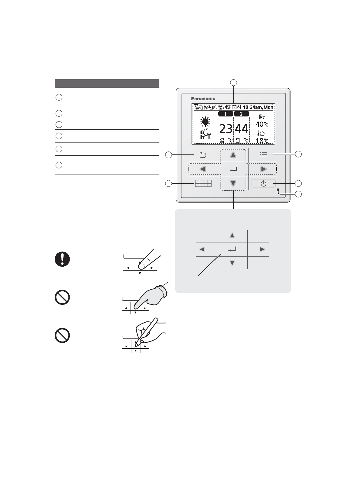
5. Location of Controls and Components
5.1 Indoor Unit
5.1.1 Remote Controller buttons and display
Buttons / Indicator
Quick Menu button
1
(For more details, refer to the separate
Quick Menu Guide.)
Back button
2
Returns to the previous screen
3 LCD Display
Main Menu button
4
For function setup
ON/OFF button
5
Starts/Stops operation
Operation indicator
6
Illuminates during operation, blinks during
alarm.
2
3
4
Press centre
No glove
No pen
1
Cross key buttons
Selects an item.
Enter button
Fixes the selected content.
5
6
Up
RightLeft
Down
29
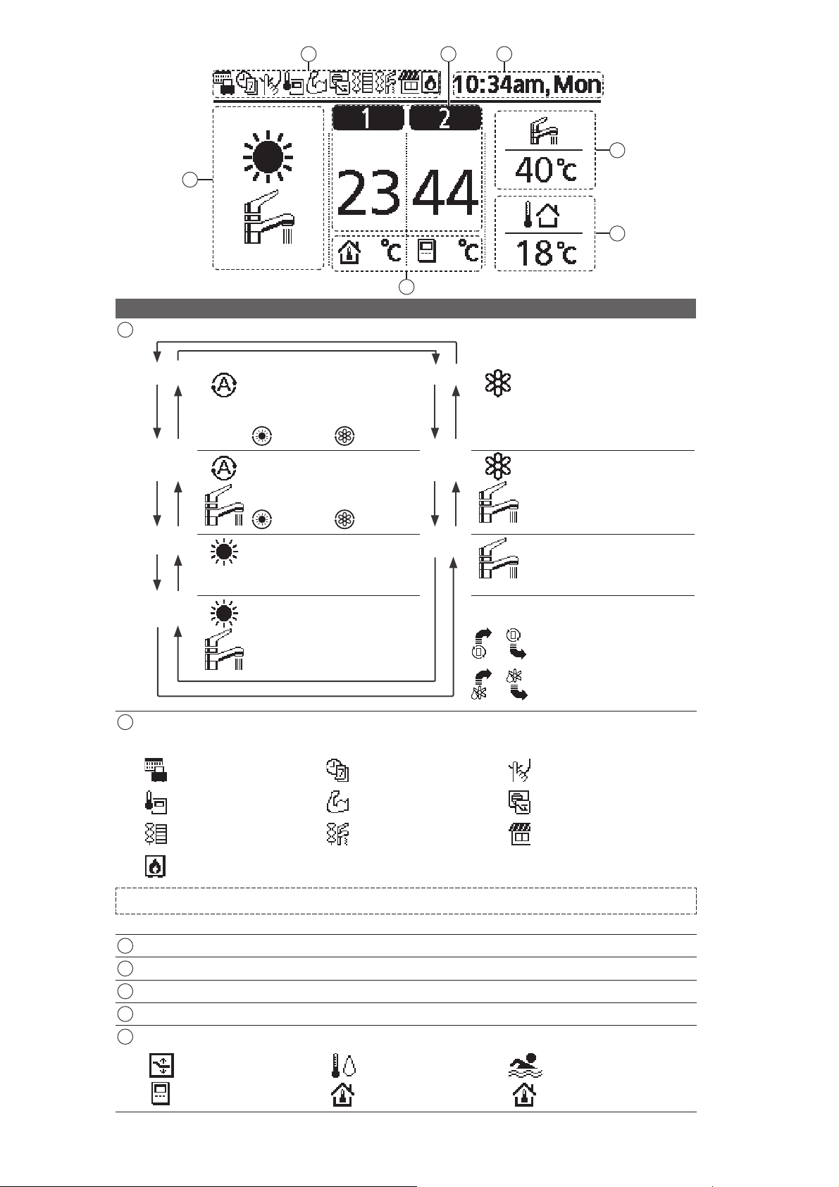
1
Display
1 Mode selection
2 43
5
6
7
1, *2
*
AUTO
• Depending on the preset outdoor
temperature, the system selects
HEAT or *
1, *2
COOL operation
mode.
1, *2
*
AUTO
+ TANK
Auto Heat Auto Cool
• Depending on the preset outdoor
temperature, the system selects
HEAT + TANK or *
1, *2
COOL +
TANK operation mode.
HEAT
Auto Heat Auto Cool
• HEAT operation is either turned
ON or OFF.
• The outdoor unit provides heat to
HEAT
+ TANK
the system.
• The outdoor unit provides heat to
the water tank and the system.
1, *2
COOL • COOL operation is either turned
*
ON or OFF.
• The outdoor unit provides cooling
to the system.
1, *2
COOL
*
+ TANK
• The outdoor unit provides cooling
to the system.
• The outdoor unit provides heating
when boiling tank.
TANK
• TANK operation is either turned
ON or OFF.
• The outdoor unit provides heat to
the water tank.
* The direction icons point to the currently
active mode.
• This mode can be selected only
when the water tank is installed.
• Room operation / Tank operation.
• Deice operation.
Operation icons
2
The status of operation is displayed.
Icon will not display (under operation OFF screen) whenever operation is OFF except weekly timer.
Holiday operation status Weekly Timer operation status Quiet operation status
Zone: Room Thermostat
→Internal sensor status
Powerful operation status
Demand Control or
SG ready or SHP status
Room Heater status Tank Heater status Solar status
Bivalent status
(Boiler)
*1The system is locked to operate without COOL mode. It can be unlocked only by authorised installers or our authorised service partners.
2
*
Only displayed when COOL mode is unlocked (This means when COOL mode is available).
3 Temperature of each zone
4 Time and day
5 Water Tank temperature
6 Outdoor temperature
7 Sensor type/Set temperature type icons
Water Temperature
→Compensation curve
Room Thermostat
→External
Water Temperature
→Direct
Room Thermostat
→Internal
Pool only
Room Thermistor
30
 Loading...