

Panasonic WH-TD20E3E5, WH-TD30E3E5-1, WH-TD20E3E5-UK, WH-TD30E3E5-UK Service Manual
© Panasonic Corporation 2013.
Order No: RAC1309001CE
WH-TD20E3E5
WH-TD30E3E5-1
WH-TD20E3E5-UK
WH-TD30E3E5-UK
TABLE OF CONTENTS
1. Safety Precautions.............................................3
2. Specification .......................................................5
3. Features ..............................................................7
4. Tank Dimensions & Components..................... 8
4.1 WH-TD20E3E5 WH-TD30E3E5-1 ..............8
4.2 WH-TD20E3E5-UK WH-TD30E3E5-UK ..... 9
5. Water Cycle Diagram .......................................10
6. Installation Instruction.....................................11
6.1 WH-TD20E3E5 WH-TD30E3E5-1 ............11
6.2 WH-TD20E3E5-UK WH-TD30E3E5-UK ...15
7. Operation Control.............................................20
7.1 Safety Valve ...............................................20
7.2 Thermostat .................................................20
7.3 3-Way Valve ...............................................20
8. Troubleshooting Guide....................................21
9. Disassembly Instructions................................22
9.1 Replacing the Heating Element..................22
9.2 Replacing the Thermostat .......................... 22
9.3 Replacing the Sacrificial Anode .................22
PRECAUTION OF LOW TEMPERATURE
In order to avoid frostbite, be assured of no refrigerant leakage during the installation or repairing of refrigerant circuit.
WARNING
This service information is designed for experienced repair technicians only and is not designed for use by the general public.
It does not contain warnings or cautions to advise non-technical individuals of potential dangers in attempting to service a product.
Products powered by electricity should be serviced or repaired only by experienced professional technicians. Any attempt to
service or repair the products dealt with in this service information by anyone else could result in serious injury or death.

2
10.
Technical Data ..................................................23
10.1 Tank Thermistor .........................................23
11. Replacement Parts List....................................24
11.1 WH-TD20E3E5 WH-TD30E3E5-1.............24
12. Replacement Parts List....................................25
12.1 WH-TD20E3E5-UK WH-TD30E3E5-UK ...25
3
CAUTION
WARNING
WARNING
1. Safety Precautions
Read the following “SAFETY PRECAUTIONS” carefully before installation of Domestic Hot Water Tank Unit
(hereafter referred to as “Tank Unit”).
Electrical works and water installation works must be done by licensed electrician and licensed water system
installer respectively. Be sure to use correct rating and main circuit for the model installed.
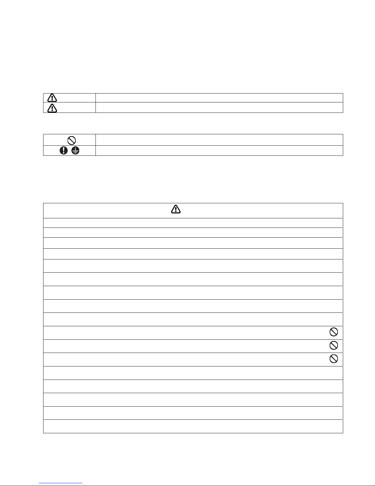
The caution items stated here must be followed because these important contents are related to safety. The
meaning of each indication used is as below. Incorrect installation due to ignorance or negligence of the
instructions will cause harm or damage, and the seriousness is classified by the following indications.
This indication shows the possibility of causing death or serious injury.
This indication shows the possibility of causing injury or damage to properties only.
The items to be followed are classified by the symbols:
Carry out test run to confirm that no abnormality occurs after the service installation. Then, explain to user the
operation, care and maintenance as stated in instructions. Please remind the customer to keep the operating
instructions for future reference.
If there is any doubt about the installation procedure or operation, always contact the authorized dealer for advice
and information.
1. Do not modify the machine, part, material during repairing service.
2. If wiring unit is supplied as repairing part, do not repair or connect the wire even only partial wire break. Exchange the whole wiring unit.
3. Must engage an authorized dealer or specialist for installation and servicing. If installation or servicing is defective, it will cause water leakage,
electrical shock or fire.
4. Install according to the installation instructions strictly. If installation is defective, it will cause water leakage, electrical shock or fire.
5. Use the attached accessories parts and specified parts for installation. Otherwise, it will cause the set to fall, water leakage, fire or electrical
shock.
6. Install at a flat horizontal, strong and firm location which is able to withstand the Tank Unit’s weight. If the location is slanting. or strength is not
enough the set will fall and cause injury.
7. For electrical work, follow the local national wiring standard, regulation and the installation instruction. An independent circuit and single outlet
must be used. If electrical circuit capacity is not enough or defect found in electrical work, it will cause electrical shock or fire.
8. Only use the supplied and specified installation parts. Else, it may causes Tank Unit vibrate, water leakage, electrical shock or fire.
9. This Tank Unit can only be used in a close water system. Utilization in an open water system may lead to excessive corrosion of the water
piping, water leakage or under pressure to the Tank Unit.
10. Do not make any purchase of electrical parts locally for installation, service, maintenance, etc. This should be done by a licensed
electrician and an authorized dealer. Otherwise, it may cause electrical shock or fire.
11. Do not branch the power from terminal block to heater tap. Overloaded terminal block will cause electrical shock or fire.
12. Keep plastic bag (packaging material) away from small children, it may caused suffocation.
13. For cold water supply has a backflow regulator, check valve or water meter with check valve, provisions for thermal expansion of water in the
hot water system must be provided. Otherwise it will cause water leakage.
14. The piping installation work must be flushed before Tank Unit is connected to remove contaminants. Contaminants may damage the Tank Unit
components.
15. The installation may be subjected to building regulation approval applicable to respective country that may require to notify the local authority
before installation.
16. The Tank Unit must be shipped and stored in upright condition and dry environment. It may laid on its back when being moved into the
building.
17. Work done to the Tank Unit after remove the front plate cover that secured by screws, must be carried out under the supervision of authorized
dealer and licensed.
Symbol with white background denotes item that is PROHIBITED from doing.
Symbol with dark background denotes item that must be carried out.
4
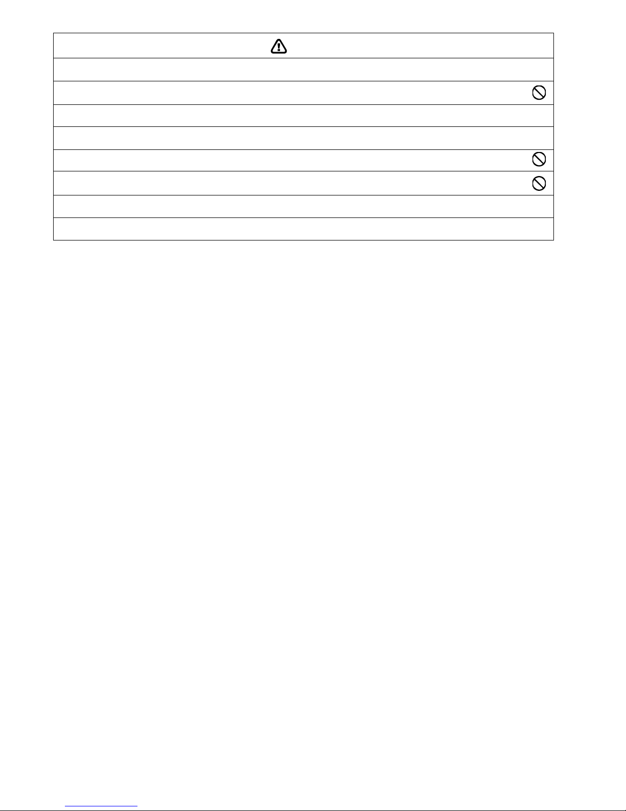
CAUTION
1. Installation work.
Three people are required to carry out the installation work. The weight of Tank Unit might cause injury if carried by one person.
2. Do not install Tank Unit at place where leakage of flammable gas may occur. In case gas leaks and accumulates at surrounding of the
Tank unit, it may cause fire.
3. Carry out drainage piping as mentioned in installation instructions. If drainage is not perfect, water leakage may happen and may cause
damage to properties of the user.
4. Select an installation location where it is accessible for maintenance.
5. Do not install this appliance in a laundry room or other high humidity location. This condition will cause rust and damage to the Tank
unit.
6. Make sure the power supply cord does not contact with hot part (i.e. water piping). High temperature may cause insulator of power
supply cord damage hence electrical shock or fire.
7. After installation or servicing, it is obliged to verify correct operation of the Tank Unit. Check the connection points for water leakage. If leakage
occurs, it will cause damage to other properties.
8. Ensure the correct polarity is maintained throughout all wiring. Otherwise, it will cause electrical shock or fire.
5
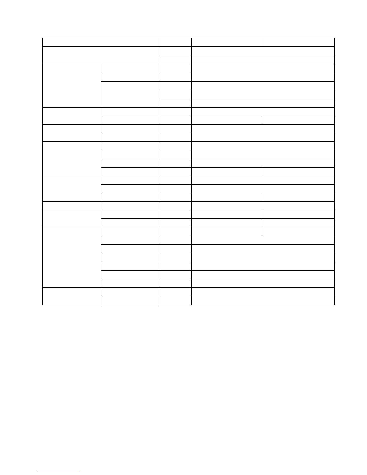
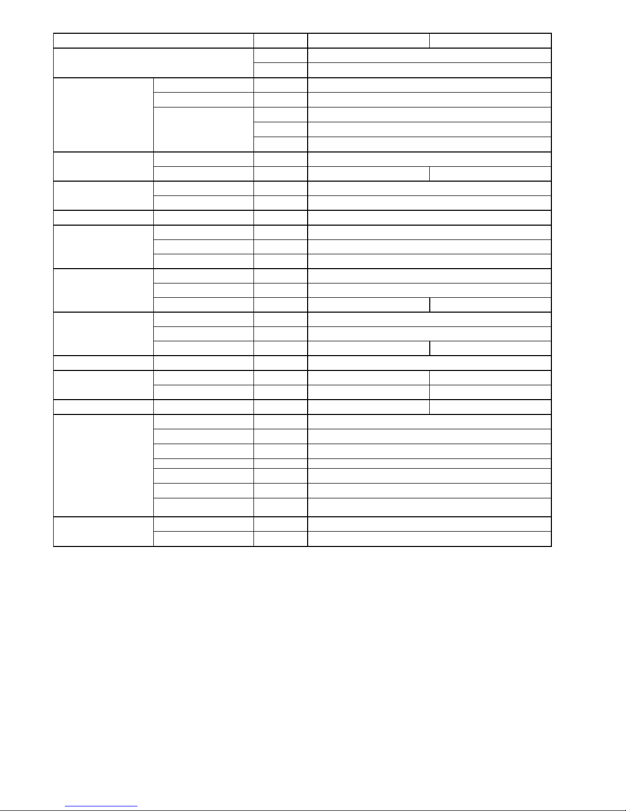
2. Specification
Model WH-TD20E3E5 WH-TD30E3E5-1
Phase, Hz Single, 50
Power Supply
V 230
Connection inch Stainless Steel 5/4 (CW602N brass quality)
Material Incoloy 825
kW 3
Btu/h 10243
Electric Element
Capacity
kJ/h 10800
Material Stainless Steel F18MT / AISI 444 / DIN 1.4521
Pressure vessel
Volume L 198 287
Type Thermodisc type TS2 59/66T (300136)
Thermostat
Temperature range °C 60 - 90, preset at 88
Thermistor Set Temperature °C 40 ~ 75
Material Stainless Steel LDX 2101 / DIN 1.4162 (Lean Duplex)
Diameter / Thickness mm Ø 22 / 0.8
Heating coil
Surface area m
2
1.4 1.8
Material ECO Foam - PUR
Thickness mm 40
Insulation
Heat loss kW Approx. 2.1 / 24hours Approx. 2.7 / 24hours
Insulation Jacket Material Epoxy-coated steel - 90 gloss - white
Diameter mm 580 580
Dimension
Height mm 1150 1600
Weight Net kg 49 65
Cold water inlet inch 3/4 BSP (with inside baffle plate)
Hot water outlet inch 3/4 BSP
Drain inch 3/4 BSP (same connection as cold water inlet)
Flow & return inch 2 × 3/4 BSP
Sensor pocket inch 2 × 1/2 BSP
Connection
Anode inch 3/4 BSP
Design pressure bar 10
Design data
Design temperature °C 99
6
Model WH-TD20E3E5-UK WH-TD30E3E5-UK
Phase, Hz Single, 50
Power Supply
V 230
Connection inch Stainless Steel 5/4 (CW602N brass quality)
Material Incoloy 825
kW 3
Btu/h 10243
Electric Element
Capacity
kJ/h 10800
Material Stainless Steel F18MT / AISI 444 / DIN 1.4521
Pressure vessel
Volume L 198 287
Type Thermodisc type TS2 59T/66T (300159)
Thermostat
Temperature range °C 55 - 85, preset at 79
Thermistor Set Temperature °C 40 ~ 75
Pressure relief tolerance % + / - 5
Temperature relief °C 90 - 95
Temperature & Pressure
Valve
Discharge capacity kW 10
Material Stainless Steel LDX 2101 / DIN 1.4162 (Lean Duplex)
Diameter / Thickness mm Ø 22 / 0.8
Heating coil
Surface area m
2
1.4 1.8
Material ECO Foam - PUR
Thickness mm 40
Insulation
Heat loss kW Approx. 2.1 / 24hours Approx. 2.7 / 24hours
Insulation Jacket Material Epoxy-coated steel - 90 gloss - white
Diameter mm 580 580
Dimension
Height mm 1150 1600
Weight Net kg 49 65
Cold water inlet inch 3/4 BSP (with inside baffle plate)
Hot water outlet inch 3/4 BSP
Drain inch 3/4 BSP (same connection as cold water inlet)
Flow & return inch 2 × 3/4 BSP
Sensor pocket inch 2 × 1/2 BSP
Anode inch 3/4 BSP
Connection
Temperature & Pressure
valve
inch 3/4 × 1/2 BSP
Design pressure bar 10
Design data
Design temperature °C 99
1. This T&P valve (TPR15) for WH-TD20E3E5-UK and WH-TD30E3E5-UK must be used 75°C and under.

7
3. Features
A hot water storage tank with capacity of 300Litres and 200Litres
High Efficiency
High Durable
o Made of clean stainless steel, the tank is designed to provide long lasting durability and toughness and
exceptional resistance to rust.
Maximum convenience and safety
o Hot water setting temperature of tank:40°C ~ Max 75°C.
(Set by remote control of indoor unit)
Safety by 2 thermostats
o 1
st
stage Set 88°C (Can be cancelled by remote control)
o 2
nd
stage Set 95°C (Can be cancelled by thermostat reset button)
Maximum compatibility
o Built-in coil in stainless steel which is designed for circulation from solar panel, etc.
Serviceability Feature
o Easy draining of the heater with a drain valve on the pressure relief valve.
8
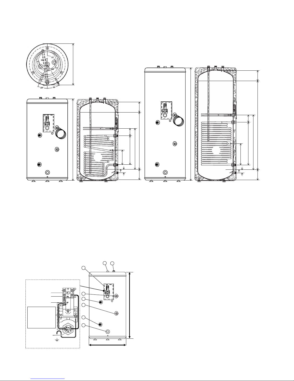
4. Tank Dimensions & Components
4.1 WH-TD20E3E5 WH-TD30E3E5-1
1150
148148 800
575
100410
205
46
65
148148 1250
765
100600
300
46
65
1,4m
2
1,8m
2
Unit: mm
580
1600
WH-TD20E3E5 WH-TD30E3E5-1
Main Components
1. Hot water outlet – 19.05 mm (3/4"BSP)
2. Electrical box lid
3. Sensor socket – 12.70 mm (1/2"BSP)
4. Flow inlet – 19.05 mm (3/4"BSP)
5. Return outlet – 19.05 mm (3/4"BSP)
6. Cold water inlet – 19.05 mm (3/4"BSP)
7. Threaded Sensor hole for solar station connection
– 12.70 mm (1/2"BSP)
8. Anode connector – 19.05 mm (3/4"BSP)
Electrical Box Detail
Diameter
Height
Resetbutton
Safetycut-out
Thermostat
Electric element
5/4"BSP
Remove this jumper
when connecting
the Tank Unit to a
PanasonicAir-to-Water
Heatpump Indoor Unit
(except S*H model)
8
1
2
3
4
7
5
6
 Loading...