

Panasonic WhisperCeiling FV-05, WhisperCeiling FV-08, WhisperCeiling FV-11VQ3, WhisperCeiling FV-15VQ4 Service Manual
Service Manual
PEG0506012CE
Version:0701
CONTENTS
1. Parts Identification
3. Parts List
2.Wiring Diagram
PAGE
1~12
14~19
13
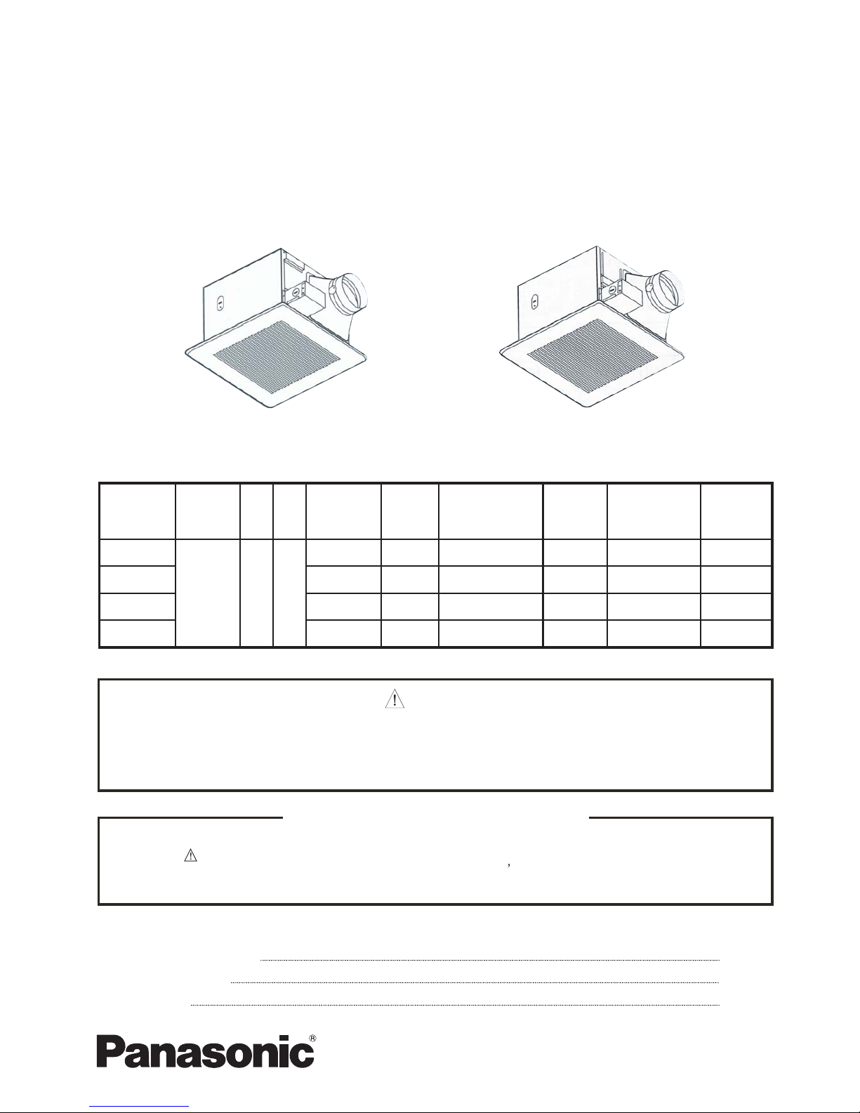
Ceiling Mount Ventilating Fan
Version A
SPECIFICATIONS
FV-05/08/11VQ3,FV-15VQ4
Version B
WARNING
This service information is designed for experienced repair technicians only and is not designed for use by
the general public. It does not contain warnings or cautions to advise non-technical individuals of potential
dangers in attempting to service a product. Products powered by electricity should be serviced or repaired
only by experienced professional technicians. Any attempt to service or repair the product or products dealt
with in this service information by anyone else could result in serious injury or death.
IMPORTANT SAFETY NOTICE
There are special components used in this equipment which are important for safety. These parts are
marked by in the Schematic Diagrams, Exploded Views and Replacement Parts List. It is essential
that these critical parts should by replaced with manufacturer s specified parts to prevent shock, fire
or other hazards. Do not modify the original design without permission of manufacture.
(North American Market)
WhisperCeiling
TM
Duct
diameter
Noise
Power
consumption
Speed
Air deliver at
0.1"WG
Weight
(inches) (sones) (W) (rpm) (cfm) Ib.(kg)
Model No.
Air
direction
VHz
<0.3 13.0 820FV-05VQ3
Exhaust 120 60
FV-11VQ3
50 11.7(5.3)
FV-08VQ3 4 0.3 23.0 730 80 12.6(5.7)
4
14.1(6.4)
4 0.8 31.0 810
Sepcifications are based on HVI standard.
110 13.0(5.9)
FV-15VQ4 6 0.6 32.0 670 150
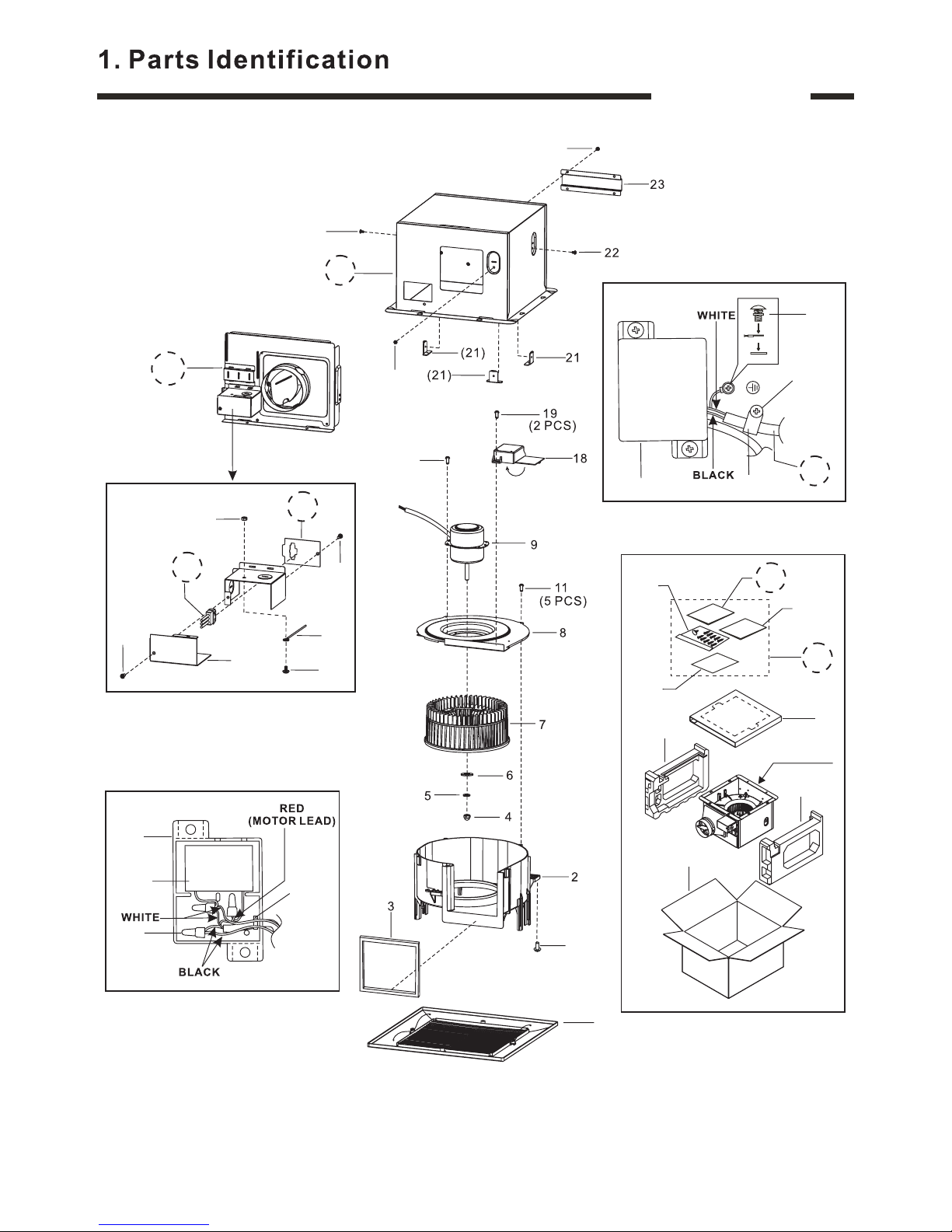
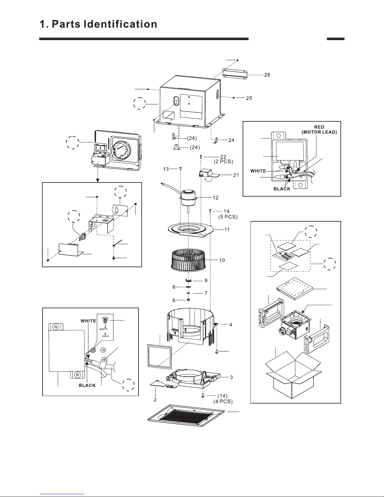
FV-05VQ3
24(4 PCS)
(22)
(22)
(18)
Details of Capacitor Box
12
14
(3PCS)
13
1
(18)
16
17B
15
(19)
Details of Wiring Section
10
(4PCS)
Main Packing Materials
34
36
33B
37
35
Installation
Instruction
WARRANTY
Installation
Instruction
EnglishEnglishEnglish
Spanish/French
(3PCS)
26
25B
20
Details of Junction Box
27
30
(30)
32
(15)
31
28B
29B
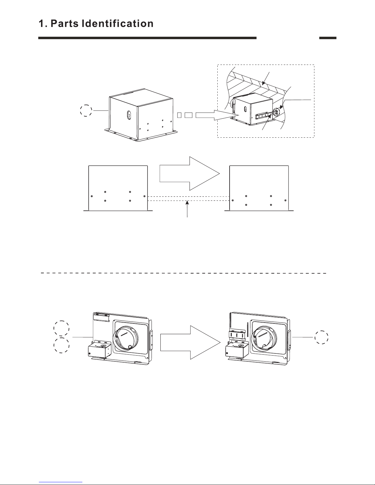
Remark: Because of different structure, we divide this model into Version A & Version B.
In Version A, we also divide into Style A & Style B. The change points are mainly
refer to the installation method and the cord section, please pay attention to the
parts which circled with broken line , you can for
details.
refer to the following 3 pages
Fan body
1
45B
47
46
48
FV-05VQ3
Parts For Version A
25AA
25AB
38
39
41
40
LR-03
LP-03
(17A)
Style A
(28A)
(29A)
VLR-03
VLP-03
(17B)
Style B
(28B)
(29B)
27
30
(30)
32
(15)
31
28B
29B
27
30
(30)
32
(15)
31
28A
29A
Details of Connector Cord
Details of Connector Cord
Details of Junction Box
Details of Junction Box
2
FV-05VQ3
43
44
42
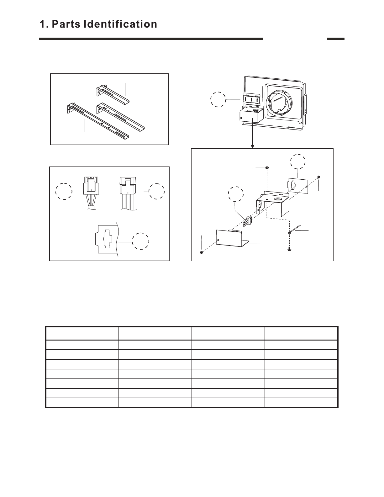
Installation Attachment
VLR-03
VLP-03
(17B)
(28B)
(29B)
Details of Connector Cord
27
30
(30)
32
(15)
31
28B
29B
25B
Details of Junction Box
3
Parts For Version B
List For Parts Differentiation
Part name Style A of Version A Style B of Version A Version B
Cord 17A 17B 17B
Frame Assy. 20 20 20
Adapter Assy. 25AA 25AB 25B
Connector Plate 28A 28B 28B
Connector Assy. 29A 29B 29B
Accessory Set 33A 33A 33B
Installation Instruction 45A 45A 45B
Remarks: For your convenience, we list the differentiation parts above, when you need to
order these parts, please judge which version or style is adapt to your machine
first. Especially, if you need to order the Frame Assy. or Adapter Assy.,please
refer to the following 1 page for details.
FV-05VQ3
Attention:
For Version B
For Version A
For Version B
25B
Guide For Frame Assy. Order
Differentiation point
Guide For Adapter Assy. Order
Change to
For Version A
Change to
25AB
20
Suspension Bracket
Joist
Fixing Position
25AA
4
Notice: 1.In order to adapt the market demand, the Adapter Assy. has been upgraded to
Version B ,therefore, the Version A part will be provided no longer.
2.If this part in your machine belongs to Version B ,you can order the item 25B
(Part No.:FFV0000029S) directly.
3.If machine belongs to Version A ,you can order the item 25AA
( FFV0000018S ),or item 25AB( FFV0000044S) as usual, then
we will not only the Version B part ,but also provide a set of installation
parts to you, those installation parts will be offered free. However, to finish this
conversion, you need to re-adjust the installation method.
this part in your
Part No.: Part No.:
provide
Notice: The Frame Assy. has been upgraded to Version B, therefore, we can provide the
Version B part at present, If this part in your machine belongs to Version A, when
you receive the Version B part, in order to install successfully, you only need to
re-adjust the fixing position of the Suspension Bracket.
For Reference
FV-08/11VQ3
(25)
(25)
27(4PCS)
(21)
(21)
18
19B
Details of Capacitor Box
15
17
(3PCS)
16
20
(22)
5
Details of Wiring Section
(4PCS)
(3PCS)
29
Main Packing Materials
37
39
40
5
38
28B
23
Details of Junction Box
30
33
(33)
35
(20)
34
31B
32B
Fan body
1
36B
Installation
Instruction
WARRANTY
Installation
Instruction
EnglishEnglishEnglish
Spanish/French
48B
50
49
51
Remark: Because of different structure, we divide this model into Version A & Version B.
In Version A, we also divide into Style A & Style B. The change points are mainly
refer to the installation method and the cord section, please pay attention to the
parts which circled with broken line , you can for
details.
refer to the following 3 pages
 Loading...