How it Works
Log In / Sign Up
Buy Points
How it Works
FAQ
Contact Us
Questions and Suggestions
Users
Panasonic
Loading...
V
VQT4J90
VQT5C27
VQT5G33
VQT9958
VQTB0088D
VR6448
VRF
VS2
3
VS3
9
VS6
8
VS7
3
VSK0317
2
VSK0492
VSK0493
VT20T
VT25
2
VT50X
VT5O
VT60D
VT60M
VV-1300
39
VV-1301
2
VV-1302
2
VV-1303
VV1303A
VV1303B
VV1307
2
VV1308
VV-1309
2
VV-1310W
39
VV-1311W
VV1317W
2
VV1318W
VV-1319W
3
VV1330S
VV-13F1
VV-2000
39
VV-2001
VV2002
VV-2003
VV2003A
VV2007
2
VV-2009
VV2017W
2
vv-2507
VVF32H122G00
VVF42F118G00
VVH19H101G00
VVX19H101G00
VVX21F136J00
VVX26F134H00
VVX32H101G00
VVX32H110G00
VW-A11
VW-A18
VW-ACT380E
VW-ACT380PP
VW-AM10-1
vw-am10-2
VW-AS1
VW-BCV1E
VW-BN1
8
VW-BN1E-GK-PP
VW-BN2
6
VW-BN2PP
2
VW-BTA1
VW-BTA1E
VW-BTA1GC
vw-clt1
VW-CLT1E-H
VW-CLT1P
VW-CLT2
2
VW-CLT2E-H
VW-CTA100
vw-cta1k
VW-CTR1E
5
VW-CTR1EB
5
VW-DTA1E
VW-DTA29
2
VW-DTA29E
2
VW-DTA30
VW-DTA30E
VW-DTM20E
2
VW-DTM21E
2
VW-DTM22E
2
VW-EC310E
2
vw-hma1k
VW-LDC10E
VW-LDH3E
VW-LED1E
4
vw-mka1k
vw-pt2
VW-R17E
VW-R88E
VW-SAA1
vw-tma1k
VW-VBN260E-K
VW-VBT190
VW-VBT190E-K
VW-VBT380
Loading...
Loading...
Nothing found
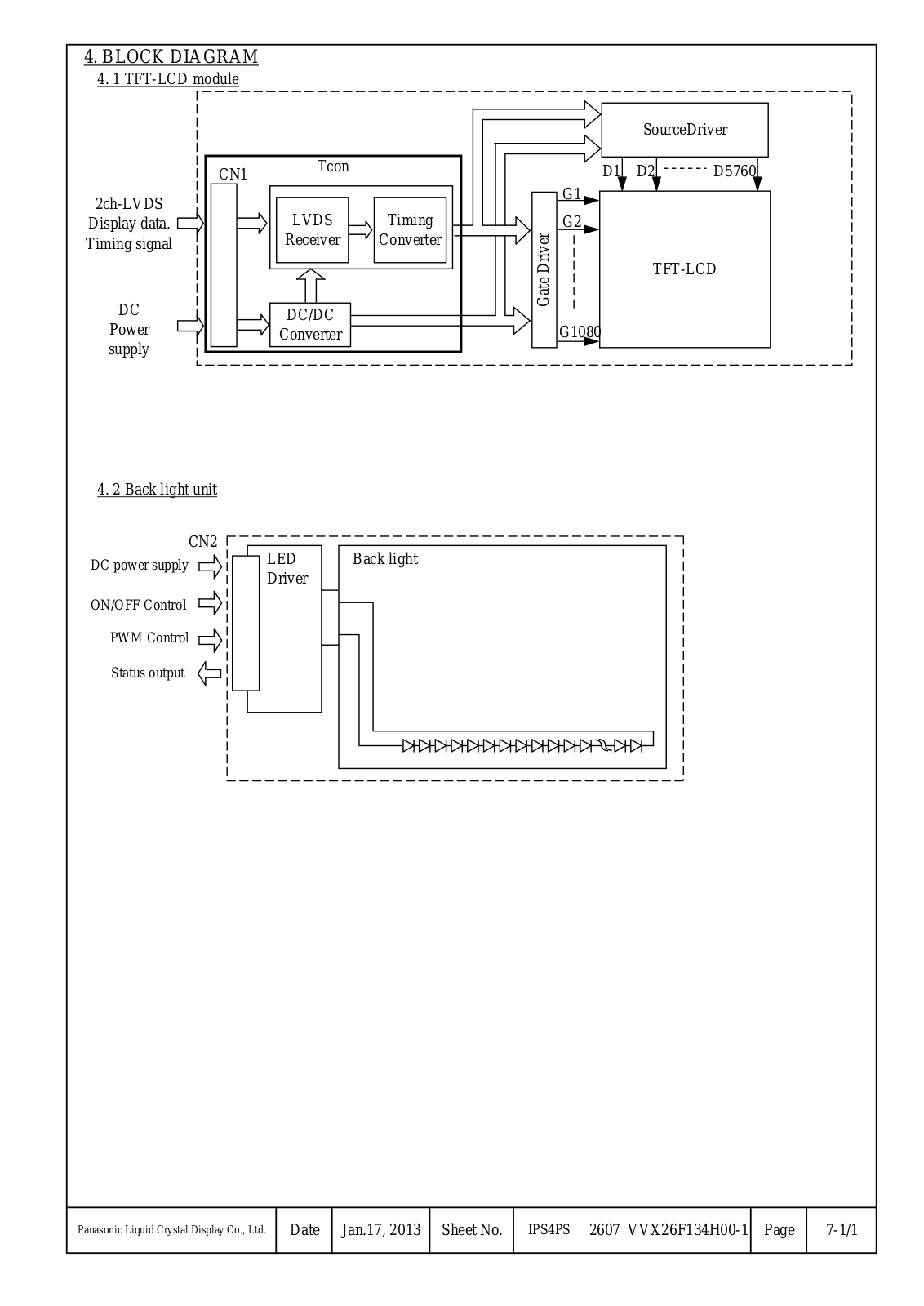
VVX26F134H00
Specification
28 pgs
420.07 Kb
0
Table of contents
Loading...
Panasonic VVX26F134H00 Specification
...
Panasonic Specification
Download
Specifications and Main Features
Frequently Asked Questions
User Manual
Download
Loading...
+
19
hidden pages
Unhide
You need points to download manuals.
1 point = 1 manual.
You can buy points or you can get point for every manual you upload.
Buy points
Upload your manuals
 Loading...