

Panasonic VVF32H122G00 Specification

Global LCD Panel Exchange Center
㪫㪜㪥㪫㪘㪫㪠㪭㪜
No. Item Page
COVER
-
-
RECORD OF REVISION
DESCRIPTION
-
ABSOLUTE MAXIMUM RATINGS
1
INITIAL OPTICAL CHARACTERISTICS
2
ELECTRICAL CHARACTERISTICS
3
BLOCK DIAGRAM
4
INTERFACE PIN ASSIGNMENT
5
INTERFACE TIMING
6
DESIGNATION OF LABEL
7
COSMETIC SPECIFICATIONS
8
PRECAUTION
9
DIMENSIONAL OUTLINE
10
www.panelook.com
Date:Feb. 10, 2011
ATD-4344
TECHNICAL DATA
VVF32H122G00
CONTENTS
1-1/1
2-1/1
3-1/1
4-1/1
5-1/2~2/2
6-1/1
7-1/1
8-1/5~5/5
9-1/3~3/3
10-1/1
11-1/2-2/2
12-1/5~5/5
13-1/3~3/3
Panasonic Liquid Crystal Display Co.,Ltd.
Date Feb.10.2011 Sheet No. IPS4PS 2601 VVF32H122G00-1
One step solution for LCD / PDP / OLED panel application: Datasheet, inventory and accessory!
Page 1-1/1
www.panelook.com
Global LCD Panel Exchange Center
The upper section : Before revision
The lower section : After revision
Date
Sheet No.
www.panelook.com
RECORD OF REVISION
Summary
㪧㪸㪾㪼
Panasonic Liquid Crystal Display Co.,Ltd.
IPS4PS 2602 VVF32H122G00-1
One step solution for LCD / PDP / OLED panel application: Datasheet, inventory and accessory!
Page 2-1/1Date Feb.10.2011 Sheet No.
www.panelook.com
Global LCD Panel Exchange Center
The following specifications are applied to the following TFT open cell.
Product Name : VVF32H122G00
Effective Display Area 㧦(H)697.685×(V)392.256 (mm)
Number of Pixels 㧦(H)1,366×(V)768 (pixels)
Pixel Pitch 㧦(H)0.51075×(V)0.51075 (mm)
Color Pixel Arrangement : R+G+B Vertical Stripe
www.panelook.com
DESCRIPTION
General Specifications
Display Mode : Transmissive Mode
Normally Black Mode
Top Polarizer Type : Semi-Glare
Number of Colors 㧦16,777,216 (colors)
External Dimensions : (H)722.384 x (V)432.956 x (t)(3) (mm)
Weight :(T.B.D) (g)
Panasonic Liquid Crystal Display Co.,Ltd.
Date Page 3-1/1Feb.10.2011 Sheet No. IPS4PS 2603 VVF32H122G00-1
One step solution for LCD / PDP / OLED panel application: Datasheet, inventory and accessory!
www.panelook.com
Global LCD Panel Exchange Center
1. ABSOLUTE MAXIMUM RATINGS
1.1 Environmental Absolute Maximum Ratings
ITEM
Temperature 0 50
Humidity
Vibration
Shock
Corrosive Gas
Note 1) Temperature and Humidity should be applied to the glass surface of a TFT module,
not to the system installed with a module.
The temperature at the center of rear surface should be less than 70 on the condition of operating.
2) Ta҇40 Relative humidity should be less than 85%RH max. Dew is prohibited.
Ta㧪40 Relative humidity should be lower than the moisture of the 85%RH at 40.
3) Frequency of the vibration is between 15Hz and 100Hz. (Remove the resonance point)
4) Pulse width of the shock is 10 ms.
5) Long operation under low temperature may cause some portion of display area to be reddish for
ޓ several minutes after turning on the product.
ޓ However, it does not affect the characteristics and reliability of the product.
6) Environmental Absolute Maximum Ratings is Based on IPS Alpha Technology TFT standard module.
Leave TFT open cell alone,this environmental ratings can't be guaranteed.The users have a responsibility
in considering ability of other parts of TFT module and TFT module process.
Min.
- 4.9(0.5G) -
- 29.4(3G)
Not Acceptable Not Acceptable
Operating
2)
www.panelook.com
Storage
Max. Min. Max.
-20
2)
- 196(20G)
60
9.8(1.0G)
Unit
㧑RH
m/s
m/s
-
Note
1),5),6)
1),6)
2
2
3),6)
4),6)
6)
1.2 Electrical Absolute Maximum Ratings
ITEM SYMBOL Min. Max.
Power Supply Voltage
Input Voltage for logic
Electrostatic Durability
㨂
DD
㨂
ESD0
㨂
㨂ESD1
0 13.2
-0.3 4.0
±8
Unit
V
V1)
V 2),3)±100
Note 1)It is applied to pixel data signal and clock signal.
ޓޓޓ2)Discharge Coefficient㧦200pF-250, Environmental㧦25-70㧑RH
ޓޓޓ3)It is applied to I/F connector pins.
ޓޓޓ4)It is applied to the surface of a metallic bezel and a LCD panel.
1.3 Environmental Absolute Ratings of TFT open cell
Storage Condition : With shipping package
Storage temperatue range : 25±5䇭㷄
Storage humidity range : 50±10%RH
Shelf life : a month
Vss = 0 V
Note
2),4)kV
Panasonic Liquid Crystal Display Co.,Ltd.
Date Feb.10.2011
Sheet No. IPS4PS Page 4-1/12604 VVF32H122G00-1
One step solution for LCD / PDP / OLED panel application: Datasheet, inventory and accessory!
www.panelook.com
Global LCD Panel Exchange Center
2. INITIAL OPTICAL CHARACTERISTICS
The following optical characteristics are measured under stable conditions. It takes about 30 minutes
to reach stable conditions. The measuring point is the center of display area unless otherwise noted.
The optical characteristics should be measured in a dark room or equivalent state.
ޓޓMeasuring equipment㧦CS-1000A, or equivalent
Ambient Temperature =25ޔVDD=12.0Vޔf V=60Hzޔ
Light source is backlight of Panasonic Liquid Crystal Display Co.,Ltd. TFT standard module.
Contrast ratio
Response
time
Brightness of white B
Brightness uniformity Buni --40
Color
chromaticity
㧔CIE㧕
Variation of
color position
(CIE)
Contrast ratio at 89 ° CR89
Rise t
Fall t
Red
Green
Blue
White
Red
Green
Blue
White
%4
on - 8 20 ms 3)
off - 6 20 ms 3)
wh 350 450 -
x 0.560
[
x 0.310 0.340
[
x 0.125 0.155 0.185
[
x 0.240 0.280
[
x - - 0.04
y - - 0.04
x - - 0.04
y - - 0.04
x - - 0.04
y - - 0.04
x - - 0.04
y - -
㧩 0 °
1)
㧩 50 °
㧩 0 °,
ޓޓ 90 °,
ޓޓ180 °,
ޓޓ270 °
1)
=0°,90°,
180°,270°
6)
www.panelook.com
Typ. Max. UNIT NOTEITEM SYMBOL CONDITION Min.
800 1400
0.590 0.620
0.305 0.335 0.365
0.570
0.035 0.065 0.095
0.243 0.283 0.323
10 - - -
0.600 0.630
-- 2)
2
cd/m
㧑
0.370
-
0.320
-
0.04
4)
ޣGray scale
=255ޤ
5)
䇼Gray scale
=255䇽
Estimated value
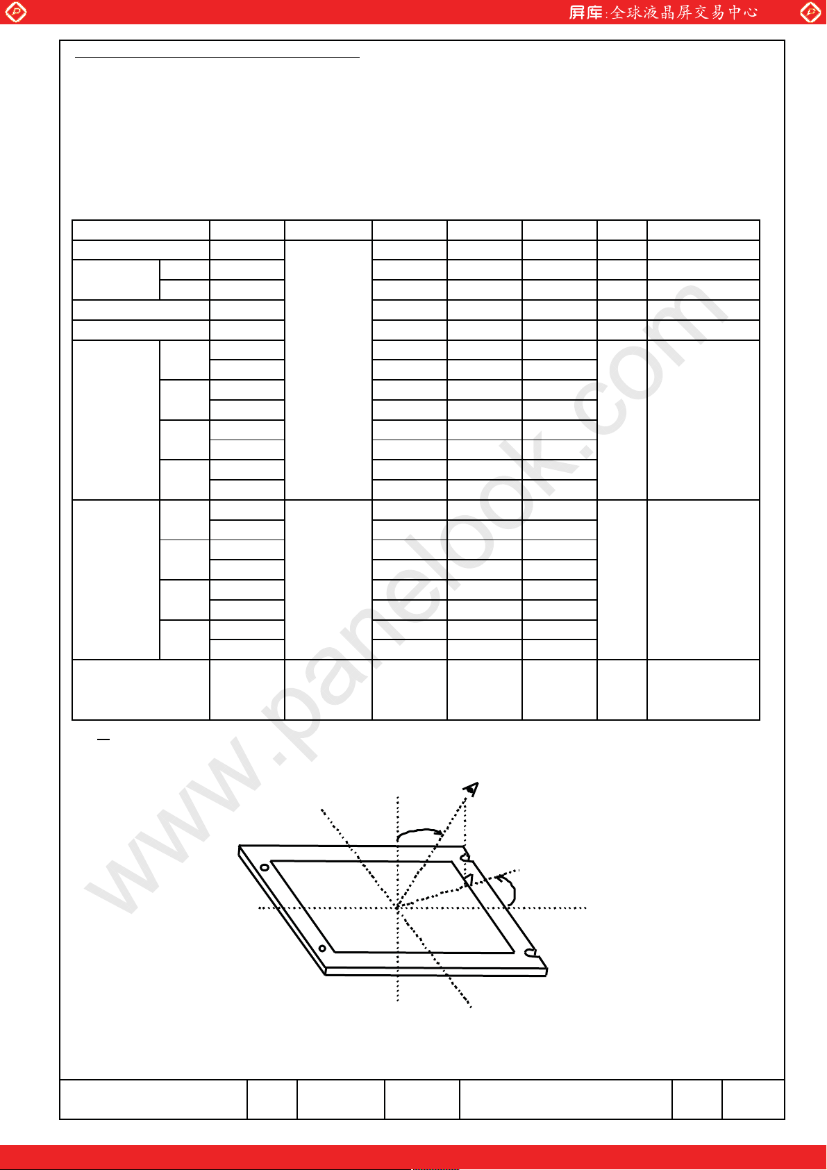
Note 1) Definition of Viewing Angle
Ǿ㧩q
㧔QENQEM㧕
Panasonic Liquid Crystal Display Co.,Ltd.
㧔QENQEM㧕
;
Ǿ㧩q
ǰ㧩q
<
G[G
ǰ
Ǿ
:
Ǿ㧩q
:㧔QENQEM㧕
6(6.%/
<
;
Ǿ㧩q
㧔QENQEM㧕
Date Feb.10.2011 Page 5-1/2Sheet No. IPS4PS 2605 VVF32H122G00-1
One step solution for LCD / PDP / OLED panel application: Datasheet, inventory and accessory!
www.panelook.com

Global LCD Panel Exchange Center
t
2) Definition of Contrast Ratio (CR)
(Luminance at displaying WHITE)
CR=
(Luminance at displaying BLACK)
3) Definition of Response Time
www.panelook.com
Displaying
㪙㪣㪘㪚㪢
Data Signal
Optical
Response
㩼
㪈㪇㪇
㪐㪇
( Luminance)
㪈㪇
4䋩 Definition of Brightness Uniformi
(1) (2) (3)
10%
90%
(4) (5) (6)
(7) (8) (9)
10%
㪇
50%
50%
90%
䋺measuring points
㪮㪟㪠㪫㪜
㫋㫆㫅 㫋㫆㪽㪽
㪙㪣㪘㪚 㪢
Display pattern is white (255 level) . The brightness
uniformity is defined as the following equation. Brightness at each
point is measured, and average, maximum and minimum
brightness is calculated.
B
B
uni=
where, B
B
B
max = Maximum brightness
min = Minimum brightness
ave = Average brightness
max or Bmin - Bave
B
Bave=
k=1
ave
9
×100
(B(k))
䋹
5䋩Variation of color position on CIE
Variation of color position on CIE is defined as difference between colors at =0°and
atǰ㧩50°& Ǿ=0°90°180°270°.
6)Contrast rasio at 89㫦
Evaluetion conditions are on horizontal & vertical axis
䇭
Panasonic Liquid Crystal Display Co.,Ltd.
One step solution for LCD / PDP / OLED panel application: Datasheet, inventory and accessory!
Date 5-2/2Feb.10.2011 Sheet No. PageIPS4PS 2605 VVF32H122G00-1
www.panelook.com
Global LCD Panel Exchange Center
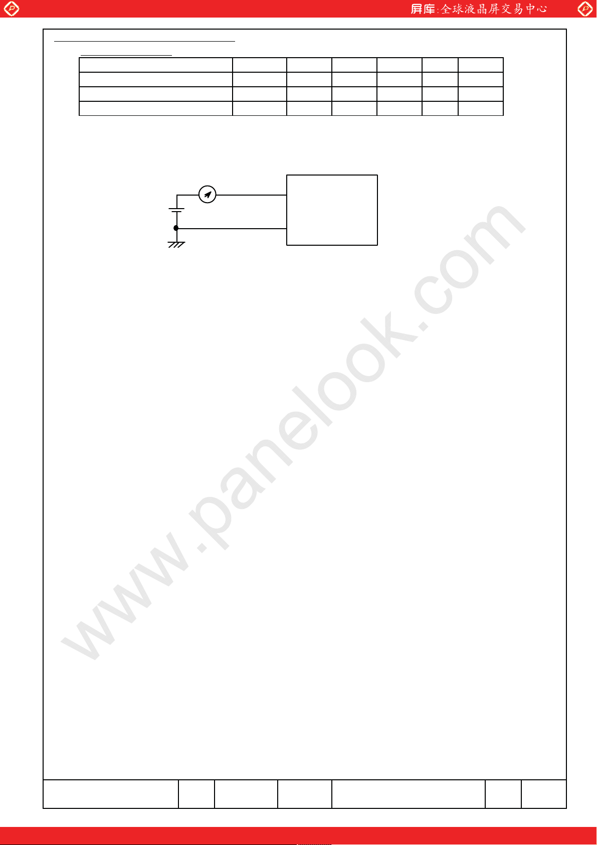
3. ELECTRICAL CHARACTERISTICS
3. 1 TFT-LCD module Ta=25ޔVss=0V
Power supply Voltage
Power supply Current
Ripple voltage of power Supply
www.panelook.com
SYSTEM
㨂
䌄䌄
㧵
䌄䌄
㨂
䌄䌄䌒
Min.
11.4
-
- 350 m㨂-
TypITEM
Max
12.0 12.6
0.4 0.8
න
㨂
㧭
⠨
1),2)
Note 1) f
V=60.0Hz䋬fCLK=85MHz䋬VDD=12.0V䋬and display pattern is white raster.
㪫㪝㪫㩷㪤㫆㪻㫌㫃㪼
㪛㪚㩷㪘㫄㫇㪼㫉㪼㩷㪤㪼㫋㪼㫉
䌖
㪛㪛
䌖
㪪㪪
2) Current fuse is built in a module. Current capacity of power supply for VDD for VDD should be larger than 4A,
so that the fuse can be opened at the trouble of electrical circuit of module.
Panasonic Liquid Crystal Display Co.,Ltd.
Date Feb.10.2011 Sheet No. IPS4PS 2606 VVF32H122G00-1
One step solution for LCD / PDP / OLED panel application: Datasheet, inventory and accessory!
6-1/1Page
www.panelook.com

Global LCD Panel Exchange Center
r
r
4. BLOCK DIAGRAM
www.panelook.com
Source
LVDS
Display data
Timing signal
DC Power supply
CN3
Tcon PCB Assy
LVDS
Receiver
DC/DC
Converte
Timing
Converter
S1 S2 S4098
G1
G2
TFT-LCD
Gate Drive
G768
One step solution for LCD / PDP / OLED panel application: Datasheet, inventory and accessory!
Panasonic Liquid Crystal Display Co.,Ltd.
7-1/1Date Feb.10.2011 Sheet No. PageIPS4PS 2607 VVF32H122G00-1
www.panelook.com

Global LCD Panel Exchange Center
5. INTERFACE PIN ASSIGNMENT
5. 1 TFT-LCD MODULE
CN3:JAE FI-X30SSLA-HF
(Matching connector : JAE FI-X30C2L)
www.panelook.com
DescriptionPin No. SYMBOL
1 VDD 1)
2 VDD
3
4 VDD
5 VSS 2)
6 VSS
7 VSS
8 VSS
9IC
10 IC
11 VSS
12 Rx0-
13 Rx0+
14 VSS 2)
15 Rx1- 3)
16 Rx1+
17 VSS 2)
18 Rx2- 3)
19 Rx2+
20 VSS 2)
21 CLK- 3)
22 CLK+
23 VSS 2)
24 Rx3- 3)
25 Rx3+
26 VSS
27 NC
28 NC
29 VSS 2)
30 VSS 2)
VDD
Power Supply (typ.+12V)
GND(0V)
Internally Connected, Keep Open
GND(0V)
Pixel Data
GND(0V)
Pixel Data
GND(0V)
Pixel Data
GND(0V)
Pixel Clock
GND(0V)
Pixel Data
GND(0V)
No Connection
No Connection
GND(0V)
GND(0V)
Note
3)
2)
Notes 1) All VDD pins shall be connected to +12.0V(Typ.).
2) All VSS pins shall be grounded. Metal bezel is internally connected to VSS.
3) Rx n+ and Rx n- (n=0,1,2,3) should be wired by twist-pairs or side-by-side FPC patterns, respectively.
Panasonic Liquid Crystal Display Co.,Ltd.
Date Feb.10.2011 Sheet No. IPS4PS 2608 VVF32H122G00-1
One step solution for LCD / PDP / OLED panel application: Datasheet, inventory and accessory!
8-1/5Page
www.panelook.com
 Loading...