

panasonic PV-M1327, PV-M1347, PV-M1357W, VV1307, VV1317W Service Manual
...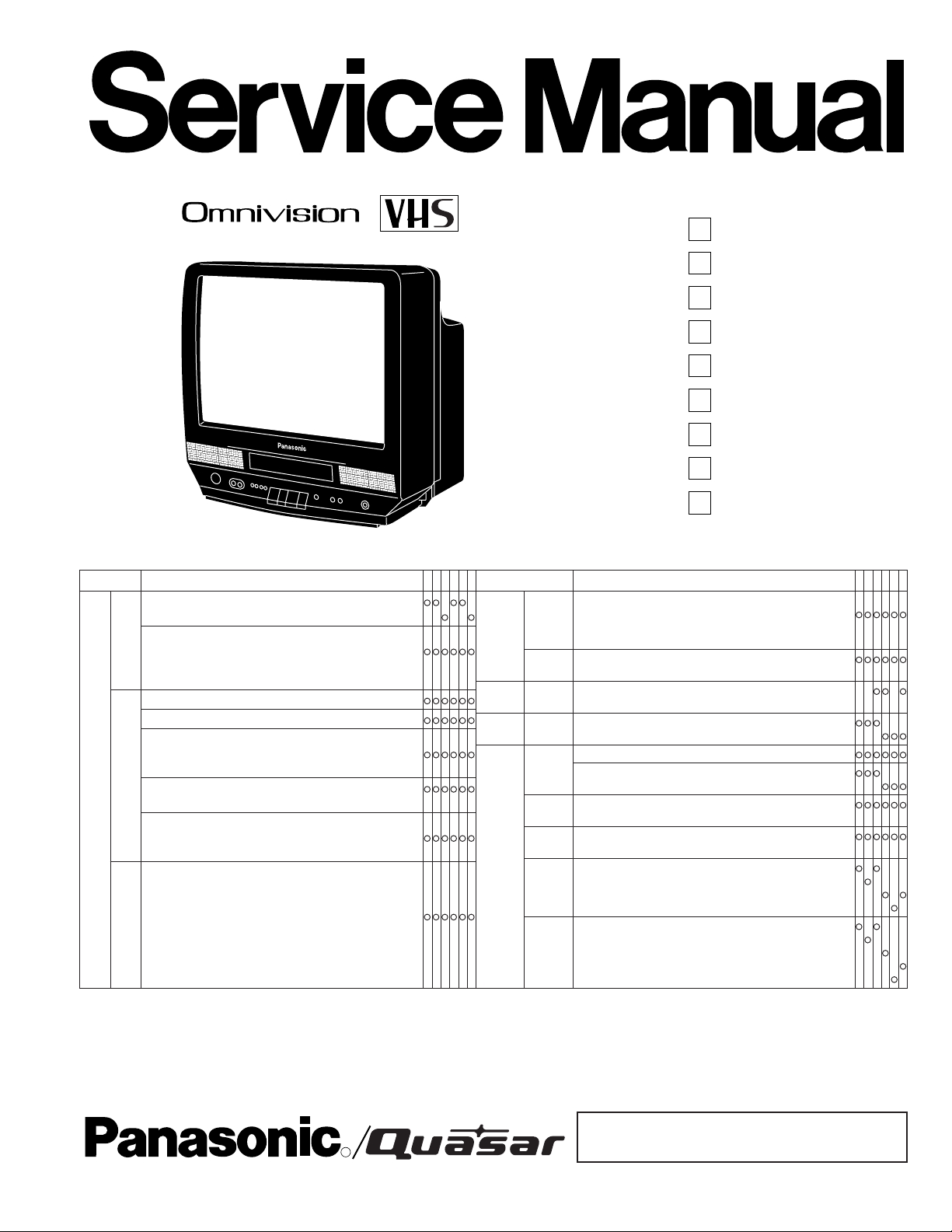
ORDER NO. MKS9701M321
B3, B6
Combination-VCR
P
PV-M1327
P
PV-M1347
P
PV-M1357W
Q
VV1307
Q
VV1317W
P
PV-M2037
P
PV-M2047
Q
VV2007
SPECIFICATIONS
ITEM SPECIFICATION
Head: 2 rotary heads helical scanning system
4 rotary heads helical scanning system
Input Level: VIDEO IN Jack (Phono type) 1.0 Vp-p 75Ω unbalanced
Video
Signal-to-Noise Ratio: SP: more than 43 dB
Horizontal Resolution: Color/Monochrome: more than 230 lines
Head: Normal Mono: 1 stationary head
Input Level: AUDIO IN Jack (Phono type) -10 dBv 50kΩ unbalanced
Frequency Response: Normal Mono: SP: 100 Hz ~ 8 kHz
Audio
VCR
1. PV-M1327
2. VV1307/VV1317W
3. PV-M1347/PV-M1357W
4. PV-M2037
5. VV2007/VV2017W
6. PV-M2047
Signal-to-Noise Ratio: Normal Mono: SP: more than 42 dB
Wow and Flutter: Normal Mono: SP Less than 0.2% WRMS
Broadcast Channels: VHF 2 ~ 13, UHF 14 ~ 69
CATV Channels: Midband A through I (14 ~ 22)
Tuner
LP/SLP: more than 41 dB
LP: 100 Hz ~ 6 kHz
SLP: 100 Hz ~ 5 kHz
LP/SLP: more than 40 dB
LP: Less than 0.3% WRMS
SLP: Less than 0.4% WRMS
Superband J through W (23 ~ 36)
Hyperband AA ~ EEE (37 ~ 64)
Lowband A-5 ~ A-1 (95 ~ 99)
Special CATV channel 5A (01)
Ultraband 65 ~ 94, 100 ~ 125
123456
- -
-- --
Q
ITEM SPECIFICATION
SP: 1-5/16 i.p.s (33.35 mm/sec), LP: 21/32 i.p.s (16.67 mm/sec),
SLP: 7/16 i.p.s (11.12 mm/sec)
Record/Playback Time: 8 Hrs with 160 min. type tape used in SLP mode
FF/REW Time: Less than 3 min. (120 min. type tape)
Tape width 1/2" (12.7 mm) high density tape
87.5 ~ 108.1 MHz
13 inch measured diagonal 90° deflection
20 inch measured diagonal 90° deflection
Source: 120V AC ± 10%, 60 Hz ± 0.5%
Consumption:Approx. 69 watts (power on), Approx. 6 watts (power off)
Approx. 110 watts (power on), Approx. 6 watts (power off)
EIA Standard (525 lines, 60 fields) NTSC Color Signal
41°F(5°C) ~ 104°F(40°C) (Temperature)
10% ~ 75% (Humidity)
15-3/16"(386mm) (W) X 15-7/8"(402.5mm) (H) X 16-11/16"(424mm) (D)
15-3/16"(386mm) (W) X 15-3/16"(385mm) (H) X 16-11/16"(424mm) (D)
20-3/10"(515mm) (W) X 19-4/5"(503mm) (H) X 19-1/10"(484mm) (D)
20-3/10"(515mm) (W) X 19-4/5"(505mm) (H) X 19-1/10"(484mm) (D)
27.4 lbs. (12.4 kg)
26.0 lbs. (11.8 kg)
49.95 lbs. (22.67 kg)
50.12 lbs. (22.75 kg)
50.67 lbs. (23 kg)
Weight and dimensions shown are approximate.
Specifications are subject to change without notice.
VCR
FM Radio
DISPLAY
GENERAL
Tape
Speed
Tape
Format
Band
Renge
Picture
Tube
Power
Television
System
Operating
Condition
Dimension
Weight
VV2017W
123456
-- -
---
---
---
---
- ---
- ----
--- -
---- -
- ---
- ----
--- --
-----
---- -
©1996 Matsushita-Kotobuki Electronics Industries LTD.
All rights reserved. Unauthorized copying and distribution
R
®
is a violation of law.
! WARNING
This service information is designed for experienced repair technicians only and is not designed for use by the general public.
It does not contain warnings or cautions to advise non-technical individuals of potential dangers in attempting to service a product.
Products powered by electricity should be serviced or repaired only by experienced professional technicians. Any attempt to service
or repair the product or products dealt with in this service information by anyone else could result in serious injury or death.
Use Marks shown in the chart below to distinguish the
different models included in this Service Manual.
MODEL MARK
PV-M1327 A
VV1307 B
VV1317W C
PV-M1347 D
PV-M1357W E
MODEL MARK
PV-M2037 F
VV2007 G
VV2017W H
PV-M2047 I
NOT USED Z
TABLE OF CONTENTS
SAFETY PRECAUTIONS................................................ 1-1
X-RADIATION.................................................................. 1-1
PREVENTION OF ESD TO ES DEVICES....................... 1-2
OPERATION GUIDE ....................................................... 1-3
SERVICE NOTES ............................................................ 1-7
IC, Transistor and Chip Part Information .................... 1-16
DISASSEMBLY/ASSEMBLY PROCEDURES
Disassembly/Assembly
Procedures of Cabinet Parts ..................................... 2-1
Disassembly/Assembly
Procedures of Mechanism ........................................ 2-7
Disassembly/Assembly
Procedures of Cassette Up Ass'y............................ 2-16
ADJUSTMENT PROCEDURES
Service Fixtures and Tools ......................................... 2-18
Mechanical Adjustment .............................................. 2-19
Electrical Adjustment .................................................. 2-26
Test Points and Control Location ............................... 2-34
SCHEMATIC DIAGRAMS
Schematic Diagram
and Circuit Board Layout Notes ................................ 3-1
Junction Schematic Diagram ........................................ 3-2
Stereo Amp Schematic Diagram .................................. 3-4
Main I (Power Supply/System Control
/Servo/Operation) Schematic Diagram ..................... 3-7
Main II (Signal Process/OSD
/Audio/Audio Amp) Schematic Diagram .................. 3-11
Main III (TV Y/C Process) Schematic Diagram .......... 3-15
Main IV (Power Supply) Schematic Diagram ............. 3-19
TV Stereo Schematic Diagram ................................... 3-19
TV Main Schematic Diagram ...................................... 3-23
CRT Schematic Diagram ............................................ 3-25
UHF/VHF Tuner/TV Demodulator
Schematic Diagram ................................................. 3-27
Head Amp Schematic Diagram .................................. 3-31
Interconnection Schematic Diagram........................... 3-37
CIRCUIT BOARD LAYOUT
Head Amp C.B.A. ......................................................... 4-1
TV Stereo C.B.A. .......................................................... 4-2
Stereo Amp C.B.A. ....................................................... 4-2
Junction C.B.A. ............................................................. 4-3
Main (Power Supply/Signal Process/OSD
/Audio/Audio Amp/TV Y/C Process
/System Control/Servo/Operation) C.B.A. ................. 4-4
TV Main C.B.A. ........................................................... 4-12
CRT C.B.A. ................................................................. 4-14
Signal Waveform ........................................................ 4-15
BLOCK DIAGRAMS
Power Supply Block Diagram ....................................... 5-1
Video Signal Path Block Diagram................................. 5-2
Audio Signal Path Block Diagram................................. 5-3
TV Stereo/Stereo Amp Block Diagram ......................... 5-5
System Control Block Diagram..................................... 5-7
Servo Block Diagram .................................................... 5-8
TV Y/C Process/OSD/CCV
/TV Main Block Diagram ......................................... 5-10
Troubleshooting Hints................................................. 5-13
EXPLODED VIEWS
1. Mechanism (Top) Section......................................... 6-1
2. Mechanism (Bottom) Section ................................... 6-2
3. Cassette Up Compartment Section .......................... 6-3
4. Chassis Frame Section (1) ....................................... 6-4
5. Chassis Frame Section (2) ....................................... 6-5
6. Packing Parts
and Accessories Section........................................... 6-6
REPLACEMENT PARTS LISTS
Before Replacing Parts, Read the Following ................ 7-1
Mechanical Replacement Parts List ............................. 7-2
Electrical Replacement Parts List ................................. 7-4
EARTH GROUND
1500Ω. 10W
0.15µF
AC VOLTMETER
Hot-Check Circuit
TO
APPLIANCES
EXPOSED
METAL PARTS
SAFETY PRECAUTIONS
GENERAL GUIDELINES
1. IMPORTANT SAFETY NOTICE
There are special components used in this equipment
which are important for safety. These parts are marked by
in the Schematic Diagrams, Circuit Board Layout,
Exploded Views and Replacement Parts List. It is essential
that these critical parts should be replaced with
manufacturer's specified parts to prevent X-RADIATION,
shock, fire, or other hazards. Do not modify the original
design without permission of manufacturer.
2. An Isolation Transformer should always be used during the
servicing of Combination VCR whose chassis is not isolated from the AC power line. Use a transformer of adequate power rating as this protects the technician from
accidents resulting in personal injury from electrical shocks.
It will also protect Combination VCR from being damaged
by accidental shorting that may occur during servicing.
3. When servicing, observe the original lead dress, especially
the lead dress in the high voltage circuits. If a short circuit
is found, replace all parts which have been overheated or
damaged by the short circuit.
4. After servicing, see to it that all the protective devices such
as insulation barriers, insulation papers, shield, and isolation R-C combinations are properly installed.
5. Before turning the receiver on, measure the resistance
between B+ line and chassis ground. Connect (-) side of an
ohmmeter to the B+ lines, and (+) side to chassis ground.
Each line should have more resistance than specified, as
follows :
B+ Line Minimum Resistance
130V 1K ohm (Hot chassis ground)
27V 180 ohms (Cold chassis ground)
17V 110 ohms (Cold chassis ground)
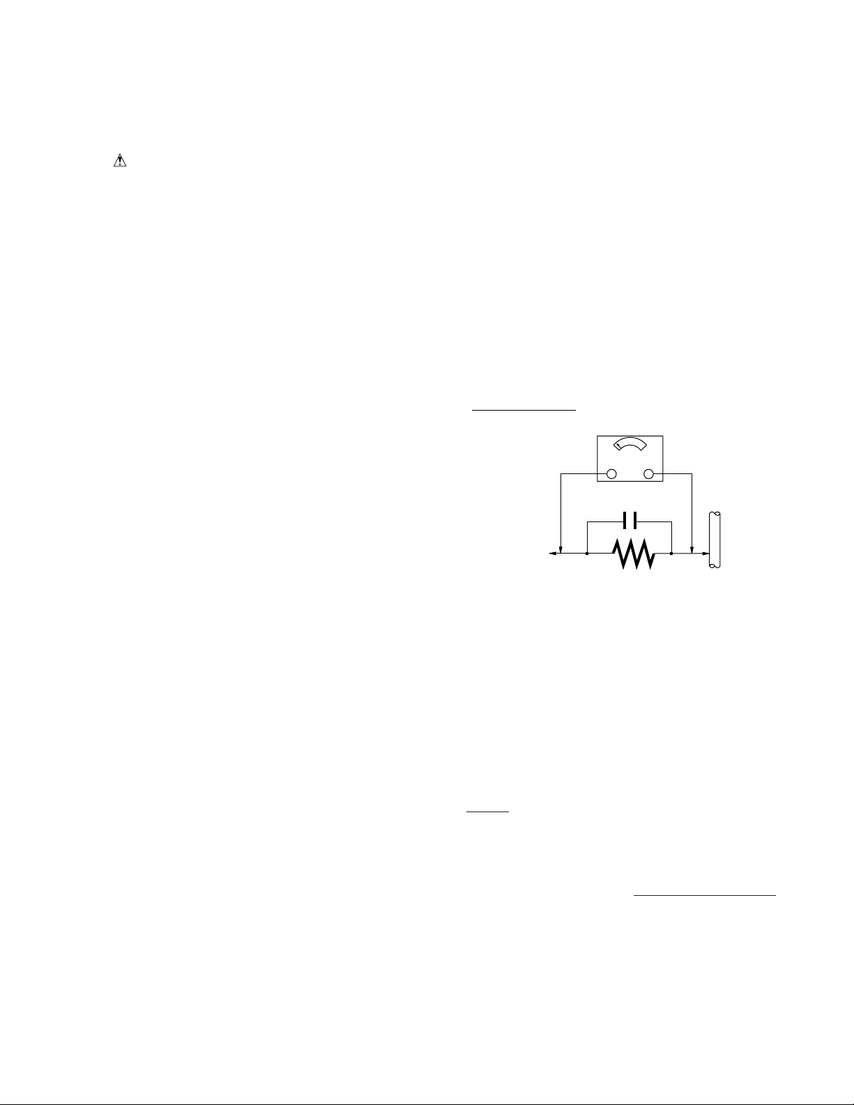
LEAKAGE CURRENT HOT CHECK
1. Plug the AC cord directly into the AC outlet.
Do not use a isolation transformer for this check.
2. Connect a 1.5K ohms, 10 watts resistor, in parallel with a
0.15 micro farad capacitor, between each exposed metallic part on the set and a good earth ground , as shown in
Figure 1.
3. Use an AC voltmeter, with 1000 ohms/volt or more sensitivity, to measure the potential across the resistor.
4. Check each exposed metallic part, and measure the voltage at each point.
5. Reverse the AC plug in the AC outlet and repeat each of the
above measurements.
6. The potential at any point should not exceed 0.75 volt RMS.
A leakage current tester (Simpson Model 229 equivalent)
may be used to make the hot checks, leakage current must
not exceed 1/2 milliampere. In case a measurement is
outside of the limits specified, there is a possibility of shock
hazard, and the receiver should be repaired and rechecked
before it is returned to the customer.
6. When the TV set is not used for a long period of time,
7. Potentials, as high as 25.0KV (Model: A, B, C, D, E) or
8. After servicing make the following leakage current checks
LEAKAGE CURRENT COLD CHECK
1. Unplug the AC cord and connect a jumper between the two
2. For physically operated power switches, turn power on.
3. Measure the resistance value, with an ohmmeter, between
unplug the power cord from the AC outlet.
30.0KV (Model: F, I) or 29.0KV (Model: G, H) are present
when this TV set is in operation. Operation of the TV set
without the rear cover involves the danger of a shock
hazard from the TV set power supply. Servicing should not
be attempted by anyone who is not thoroughly familiar with
the precautions necessary when working on high voltage
equipment. Always discharge the anode of the picture tube
to the CRT ground of receiver before handling the tube.
to prevent the customer from being exposed to shock
hazards.
prongs on the plug.
Otherwise skip step 2.
the jumpered AC plug and each exposed metallic cabinet
part on the receiver, such as screwheads, connectors, etc.
When the exposed metallic part has a return path to the
chassis, the reading should be between 1 M ohm and 12
M ohms. When the exposed metal does not have a return
path to the chassis, the reading must be infinity.
Figure 1
X-RADIATION
WARNING :
1. The potential source of X-Radiation in TV sets is the High
Voltage section and the picture tube.
2. When using a picture tube test fixture for service, ensure
that the fixture is capable of handling 25.0KV (Model: A, B,
C, D, E) or 30.0KV (Model: F, I) or 29.0KV (Model: G, H)
without causing X-Radiation.
NOTE :
It is important to use an accurate periodically calibrated
high voltage meter.
1. Reduce the brightness to minimum.
2. Set the SERVICE switch to SERVICE .
3. Measure the High Voltage.
cate 23.5 +/- 1.5KV (Model: A, B, C, D, E) or 28.5 +/- 1.5KV
(Model: F, I) or 27.5 +/- 1.5KV (Model: G, H).
If the meter indication is out of tolerance, immediate service
and correction is required to prevent the possibility of
premature component failure.
4. To prevent an X-Radiation possibly, it is essential to use the
specified picture tube.
The meter reading should indi-
1-1
PREVENTION OF ELECTRO-
HORIZONTAL OSCILLATOR
DISABLE CIRCUIT TEST
SERVICE WARNING :
The test must be made as a final check before set is returned
to the customer.
1. With the rear cover removed, supply about a 120V AC
power source to the set, turn on the set.
2. Set the customer controls to normal operating positions.
3. Short between TP891 and TP892 on the Main circuit board
with a jumper wire. Confirm that the picture goes out of
horizontal sync.
4. If this does not occur, the horizontal oscillator disable
circuit is not operating. Follow the Repair Procedures of
horizontal oscillator disable circuit before the set is returned to customer.
REPAIR PROCEDURES OF
HORIZONTAL OSCILLATOR
DISABLE CIRCUIT
1. Connect a DC voltmeter between capacitor C513 (+) on
the Main circuit board and chassis ground.
2. If approximately +21.9V is not present at that point when
120V AC is applied, find the cause. Check R503, R5505,
C5507, C513 and D503.
3. Carefully check above specified parts and related circuits
and parts. When the circuit is repaired, try the horizontal
oscillator disable circuit test again.
CIRCUIT EXPLANATION
HORIZONTAL OSCILLATOR DISABLE
CIRCUIT
STATIC DISCHARGE (ESD) TO
ELECTROSTATICALLY
SENSITIVE (ES) DEVICES
Some semiconductor (solid state) devices can be damaged
easily by static electricity. Such components commonly are
called Electrostatically Sensitive (ES) Devices. Examples of
typical ES devices are integrated circuits and some field-effect
transistors are semiconductor "chip" components. The following techniques should be used to help reduce the incidence of
component damage caused by electrostatic discharge (ESD).
1. Immediately before handling any semiconductor component or semiconductor-equipped assembly, drain off any
ESD on your body touching a known earth ground. Alternatively, obtain and wear a commercially available discharging ESD wrist strap, which should be removed for
potential shock reasons prior to applying power to the unit
under test.
2. After removing an electrical assembly equipped with ES
devices, place the assembly on a conductive surface such
as aluminum foil, to prevent electrostatic charge buildup or
exposure of the assembly.
3. Use only a grounded-tip soldering iron to solder or unsolder
ES devices.
4. Use only an anti-static solder removal device. Some solder
removal devices not classified as "anti-static (ESD protected)" can generate electrical charge sufficient to damage ES devices.
5. Do not use freon-propelled chemicals. These can generate electrical charges sufficient to damage ES devices.
6. Do not remove a replacement ES device from its protective
package until immediately before you are ready to install it.
(Most replacement ES devices are packaged with leads
electrically shorted together by conductive foam, aluminum foil or comparable conductive material).
7. Immediately before removing the protective material from
the leads of a replacement ES device, touch the protective
material to the chassis or circuit assembly into which the
device will be installed.
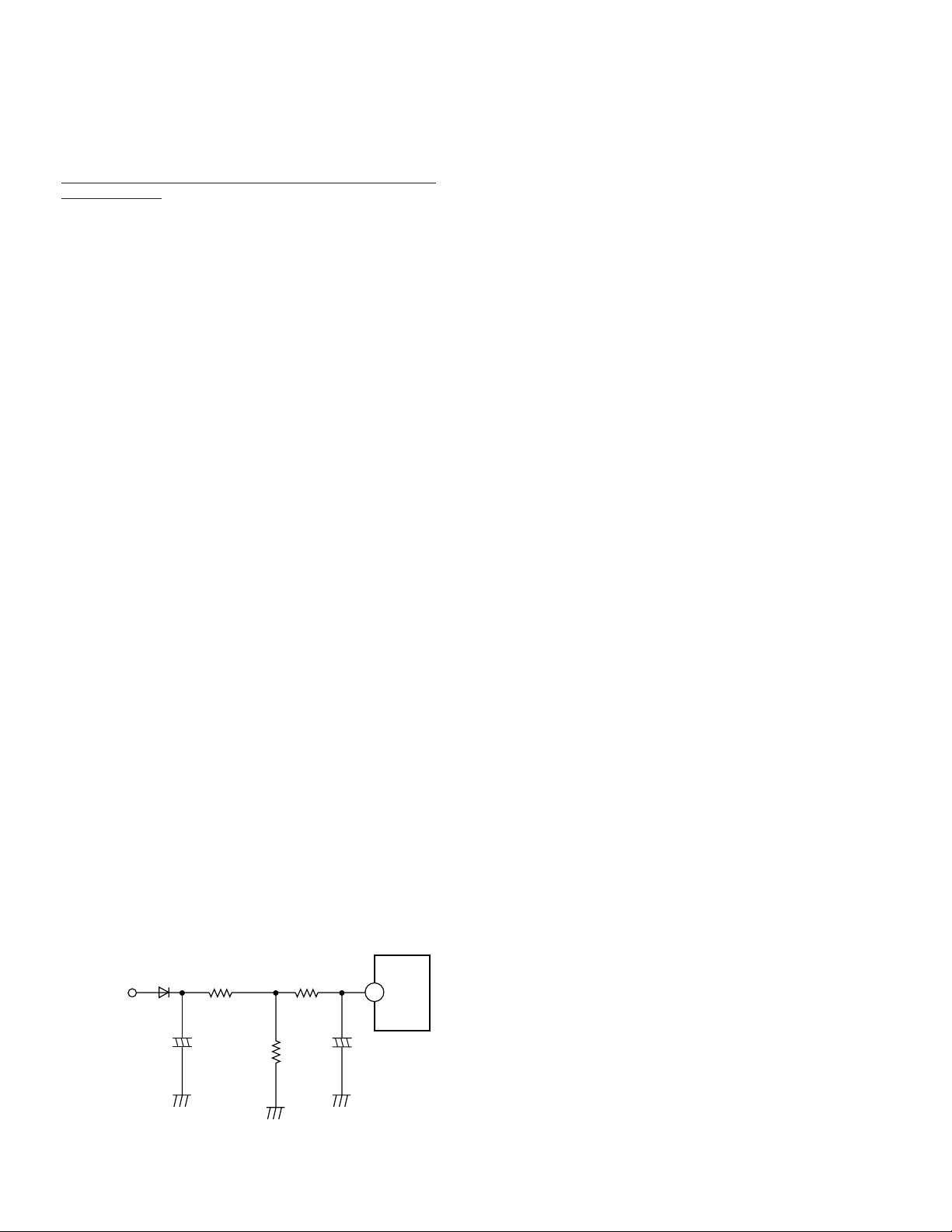
The positive DC voltage, supplied from the D503 cathode for
monitoring high voltage, is applied to the IC5301 Pin11 through
R503 and R5504. Under normal conditions, the voltage at
IC5301 Pin 11 is less than approx 3V. If the high voltage at
Flyback Tr Pin 6 exceeds the specified voltage, the positive DC
voltage which is supplied from the D503 cathode also increases. The increased voltage is applied to IC5301 Pin11
through R503 and R5504. Due to the increased voltage at
IC5301 Pin11, the horizontal oscillator frequency increases,
the picture goes out of horizontal sync, the beam current
decreases and the picture becomes dark in order to keep Xradiation under specification.
+
C5507
-
IC5301
11
To Pin 6
of Flyback
Transformer
D503
C513
+
-
R503
R5504
R5505
Figure 2
CAUTION:
Be sure no power is applied to the chassis or circuit, and
observe all other safety precautions.
8. Minimize bodily motions when handling unpackaged replacement ES devices. (Otherwise harmless motion such
as the brushing together of your clothes fabric or the lifting
of your foot from a carpeted floor can generate static
electricity (ESD) sufficient to damage an ES device).
"NOTE to CATV system installer :
This reminder is provided to call the CATV system installer's
attention to Article 820-40 of the NEC that provides guidelines
for proper grounding and, in particular, specifies that the cable
ground shall be connected to the grounding system of the
building, as close to the point of cable entry as practical."
1-2
1-3
1-4

1-5
1-6
SERVICE NOTES
Simplified Fault Finding Data
Simplified Self-Diagnostic System facilitates finding the cause
of the fault. 4 digit fault code will be displayed on TV screen.
The Simplified Fault finding data is stored in the Memory IC
(IC6004). This data is cleared after it is displayed and then, the
POWER button is pressed back on.
1. With power turned off, press FF and REW buttons on unit
together for over 3 seconds.
REW FF
Power is OFF.
2. TV power goes on and the unit goes into service mode.
Fault code indication (4 digit number) will be displayed.
Code Digit Position
• Cassette Down SW.
and S-Tab SW. Data
• Take Up Photo and
Supply Photo Sensor Data
• Present mechanism position code
• Lock code
Explanation of Codes
S-Tab SW. Data
• S-Tab SW. is off.
• S-Tab SW. is on.
Take Up and Supply Photo Sensor Data
• No light detected at either sensor.
• Take Up Photo Sensor detected at
beginning of tape.
• Supply Photo Sensor detected at end
of tape.
• Light detected at both sensors.
Present Mechanism Position Code
Mechanism Position is indicated.
(Refer to Fig. 1-4.)
Lock Code
• VCR is not in shut-off condition.
• Reel lock.
• Cylinder lock.
• Exceeds loading/unloading time.
(Mechanism Lock)
• Exceeds Cassette loading/unloading time.
(Cassette Lock)
Tape Unloading (direction)
Tape Loading (direction)
+
Fig. 1-1
Fig. 1-2
Press (Over 3 seconds)
SERVICE MODE
2192
Fault Code
TV Screen
Code No.
1
2
1
2
3
4
1
2
3
4
5
6
7
8
9
A
B
C
D
1
2
0
1
2
3
4
4
Mode
Select SW.
PLAY/CUE
/SLOW/STILL
BRAKE
FF/REW
Mechanism
position
position code
EJECT
LOAD
REV
7
8
9
A
B
C
D
1
EJECT
CASSETTE
DOWN
1 2 3 4 5 678 9 A B C D
2
STOP/
STBY
6
ABC
REV
UNLOAD
STOP
5
3
PLAY/CUE/
SLOW/STILL
4
CASSETTE
DOWN
FF/REWBRAKE
Fig. 1-4
Note:
When 1 to 4 listed in Lock code occurs, the VCR stops
and all VCR function buttons except for power become
non-operational.
3. Press any operation button except for POWER on either
the unit, or the remote to detect that a key has been
pressed.
The 1st digit changes to "0" only when key is detected.
SERVICE MODE
2192
Any operation button
Press
SERVICE MODE
0192
Changes to "0"
Fig. 1-5
Fig. 1-3
1-7
Mechanism
Chassis and
Cassette Up
Ass'y
Stereo Amp C.B.A.
(Model: I)
VCR Unit
TV Main C.B.A.
Insulated material
TV
It is not necessary to
connect Degaussing
Coil Connector
CAUTION:
HOT CIRCUIT
DO NOT
touch Power
curcuit during service.
open
Main C.B.A.
Service Position
The Basic Service Position does not require the use of Extension Cables. However, for more extensive servicing, Extension Cables should be used.
1. Basic Service Position
Service Position Purpose
Service Position (1) Mechanism check
Mechanical adjustment
Electrical adjustment
Service Position (2)
Main C.B.A. check
TV Main C.B.A. check
Service Position (1)
1. Remove Rear Cover, VCR Unit, (Stereo Amp C.B.A.:
Model I), and Top Shield Plate Ass'y.
2. Then, place VCR Unit as shown.
TV
CAUTION:
HOT CIRCUIT
C.B.A. and TV Main C.B.A.
Use extreme care to prevent accidental shock when
servicing.
Note:
When disassembling/assembling, refer to "Disassembly/
Assembly Procedures of Cabinet" section.
(Primary circuit) exists on the Main
Service Position (2)
1. Remove Rear Cover, VCR Unit, (Stereo Amp C.B.A.:
Model I), and Top Shield Plate Ass'y.
2. Place VCR Unit as shown.
In order to stabilize VCR Unit, place it on a slanted support,
such as a loose-leaf binder etc.
TV Main
C.B.A.
Main
C.B.A.
VCR Unit
Mechanism Chassis
and Cassette Up Ass'y
It is not necessary to connect
Degaussing Coil Connector
CAUTION:
HOT CIRCUIT
DO NOT
curcuit during service.
Fig. 2-1
touch Power
Fig. 2-2
1-8
Alignment
Projection
Mode Select SW. on Main C.B.A.
SERVICE
Rotate
Extension
Cable -1
Mode Select SW. Ass'y
Extension Cable -2
Full Erase Head
Connector
Mode Select
SW. Connector
(Foil Side)
P3501
P6201
P6002
Keep away these cables from
TV Main C.B.A. as possible.
Safety Tab SW.
P4001
Main C.B.A.
P3003
Frame
tape
tape
tape
masking tape
TV
TV Main C.B.A.
Mechanism
Chassis and
Cassette Up Ass'y
It is not necessary to connect
Degaussing Coil Connector
CAUTION:
HOT CIRCUIT
DO NOT
touch Power
curcuit during service.
2. Service Position with Extension Cable Kit
In Service Position with Extension Cable Kit, mechanism check from the Bottom Side of Mechanism Chassis and Capstan Stator
Unit (Capstan Motor Drive, Loading Motor Drive Circuit) check with power on condition can be performed.
Service Position
CAUTION:
HOT CIRCUIT
Use extreme care to prevent accidental shock when servicing.
Note:
When disassembling/assembling, refer to "Disassembly/Assembly Procedures of Cabinet" section.
Fig. 3-1
(Primary circuit) exists on the Main C.B.A. and TV Main C.B.A.
1-9

Extension Cable Kit (VUZS0002)
Mode Select SW. Ass'y
(VUVS0001)
8 pin
3 clip-on
wires
Extension Cable -1
(VUVS0002)
14 pin
Mode Select SW.
on Mode Select
SW. Ass'y
EJECT
Position
Alignment
Projection
Head Amp C.B.A.
P3501
P2552
Shaft of Main
Cam Gear
P2531
2 pin
Extension Cable -2
(VUVS0005)
12 pin
for 2 Head Model
Extension Cable -2
(VUVS0004)
15 pin
for 4 Head Model
Extension Cable -2
(VUVS0003)
20 pin
for Hi-Fi Model
Fig. 3-2
Note:
3 types of Extension Cable -2 are included in this kit. Since
there is a difference in the number of P3501 Head Amp C.B.A.
pins between 2 Head, 4 Head, and Hi-Fi models, be sure to use
the proper cable.
Rotate
SERVICE
Full Erase
Head Connector
Extension Cable -1
Extension Cable -2
3 Clip-on Wires connection
Orange
Yellow
Red
Not Used
2
134
(Foil Side)
Mode Select SW. Ass'y
Mode Select SW.
Main C.B.A.
IC6001
(Component Side)
See 3 Clip-on
Wires connection
How to place the unit into Service Position with
Extension Cables
1. Remove Rear Cover, VCR Unit, (Stereo Amp C.B.A.:
Model I), Top Shield Plate Ass'y, Mechanism Chassis, and
Cassette Up Ass'y.
2. Connect the Extension Cables as follows:
Extension Cable -1:
Extension Cable -2:
Mode Select SW. Ass'y:
Full Erase Head Connector on the
Mechanism Chassis Unit ~ P4001
on the Main C.B.A.
Note: No change in performance if
pins are reversed.
P3501 on the Head Amp C.B.A.
~ P3003 on the Main C.B.A.
a) 3 Clip-on Wires ~ Mode Select SW.
Connector on the Main C.B.A.
1 Pin (Not Used)
Red Wire ~ 2 pin
Orange Wire ~ 3 pin
Yellow Wire ~ 4 pin
b) 8 Pin Connector ~ P6002 on the
Main C.B.A.
c) 14 Pin Connector ~ P6201 on the
Main C.B.A.
d) Set Mode Select SW. on the Mode
Select SW. Ass'y to EJECT position
and install onto Mechanism Chassis.
1-10
Fig. 3-3
3. Place the VCR Unit as shown in Fig. 3-1.
4. Secure the Extension Cables with tape as shown
in Fig. 3-1. When recording, cover the Safety Tab SW. with
masking tape to turn this SW. on.
Note:
To avoid damaging the connectors on Main C.B.A., it is
necessary to secure connectors with tape as shown in
Fig. 3-1.
5. Set Mode Select SW. on the Main C.B.A. to Service
Position.
6. Plug the AC plug into an AC outlet.
7. Insert a cassette.
The power comes on, the tape is fully loaded, and the unit
goes into the STOP Mode.
8. Place a jumper between TP6001 and GND to place the unit
in Service Mode.
9. Check and/or repair the unit.
10. Press the STOP/EJECT button to eject the cassette.
Note:
When inserting a cassette again, remove the jumper
between TP6001 and GND and insert the cassette. Then,
reconnect the jumper.
11. After servicing, remove the jumper between TP6001 and
GND to release the unit from Service Mode.
Note:
When disassembling/assembling, refer to "Disassembly/
Assembly Procedures of Cabinet" section.

slide
Slot
Screw (A)
Drive Rack
Unit
Main Cam Gear
Guide Tab
pull
Spring (A)
Drive Rack Arm
How to Remove a jammed Tape
Manual Method
When a tape jam is encountered, check the tape loading
condition and use the following procedure to remove a tape
jam.
Yes
Main Cam Gear can
be rotated
Pinch Roller is up
against Capstan Rotor
Unit shaft
No
3. Remove the tape from the tape path.
4. Rewind the tape into the cassette by rotating the Center
Clutch Unit counterclockwise.
5. Unhook Spring (A) of the Drive Rack Unit.
6. Remove Screw (A).
7. Lift the Drive Rack Unit up so that the slot clears the guide
tab. While pulling the Drive Rack Unit out far enough so that
it clears the Drive Rack Arm,.slide the Drive Rack Unit as
indicated by the arrow to remove the cassette tape from the
Cassette Up Ass'y.
9. Check the cause of mechanical trouble and repair.
Yes
Method -1:
1. While releasing 2 Locking Tabs (A) of Opener Piece, pull
the Opener Piece up as far as you can.
2. Move the pin of Pinch Arm Unit out of the groove of the Main
Cam Gear so that the Pinch Roller is separated from the
shaft of the Capstan Rotor Unit.
Rear Side View
Opener
Piece
No
Method 1Method 2
Main Cam Gear
Method 3
Fig. 4-1
Pinch Arm
Unit
Fig. 4-3
Method -2:
1. Rotate Main Cam Gear clockwise with needlenose pliers,
etc. so that the Pinch Roller is separated from the shaft of
the Capstan Rotor Unit.
2. Perform Step 3 through Step 8 of Method -1.
Opener Piece
Pin of Pinch Arm Unit
Main Cam Gear
Locking
Tabs (A)
Pull Up
Fig. 4-2
Shaft of Capstan
Rotor Unit
Pinch
Roller
Pinch
Arm Unit
Groove
Method -3:
1. Perform Step 3 through Step 8 of Method -1.
Note:
After repairing mechanical trouble, make sure that all gear
alignments are correct, especially the Wiper Arm Unit and
Drive Rack Unit of Cassette Up Ass'y.
1-11
Electrical Method
Electrical method can only be performed when the mechanism
is moved by rotating the Main Cam Gear.
CAUTION:
If loading dose not start in approx. 2 seconds after DC
Power Supply is applied, DO NOT continue to apply DC
Power Supply. Instead, perform "Manual Method."
Method -1:
1. Remove the solder as shown and apply +10.0 VDC Power
Supply (DC + to Portion "a," DC - to Portion "c").
2. When the Loading Posts reach the fully unloaded position,
remove the Power Supply.
Motor P.C.B of
Motor Block Ass'y
P2551
Unsolder
Method -2:
1. Locate the Jumper (J6004) on the System Control Section
of the Main C.B.A. and cut it near the center.
Main C.B.A.
+
-
J6004
J6005
+
"c"
-
"b"
"a"
"b"
"a"
P2552
Rear Side View
Chassis
DC Power Supply
(+10VDC)
Fig. 5-1
Note:
Be careful not to let the DC Power Supply Unit GND contact
the chassis GND. This may damage the Loading Motor
Drive IC (IC 2501).
Be sure to apply DC + to Portion "a" of Motor P.C.B.
If DC + is applied to Portion "b", the Loading Motor Drive IC
(IC2501) may be damaged.
4. Rewind the tape into the cassette by turning the Center
Clutch Unit counterclockwise.
5. Eject the cassette by applying +10.0VDC Power Supply
again.
6. After completing the removal procedure, solder Portion "a"
and Portion "b."
Fig. 5-2
2. Apply +10.0VDC Power Supply to the jumpers. When the
Loading Posts reach the fully unloaded position, remove
the Power Supply.
Note:
Be careful not to let the DC Power Supply Unit GND contact
the chassis GND. This may damage the Loading Motor
Drive IC (IC 2501).
Be sure to apply DC + to Portion "a" of J6004.
If DC + is applied to Portion "b" of J6004, the Loading Motor
Drive IC (IC2501) may be damaged.
TV Main C.B.A.
Main C.B.A.
b
a
J6004
Motor P.C.B.
J6005
DC Power Supply
(+10.0VDC)
+
-
1-12
Fig. 5-3
4. Rewind the tape into the cassette by turning the Center
Clutch Unit counterclockwise.
5. Eject the cassette by applying +10.0VDC Power Supply
again.
6. After completing the removal procedure, resolder Jumper
(J6004).
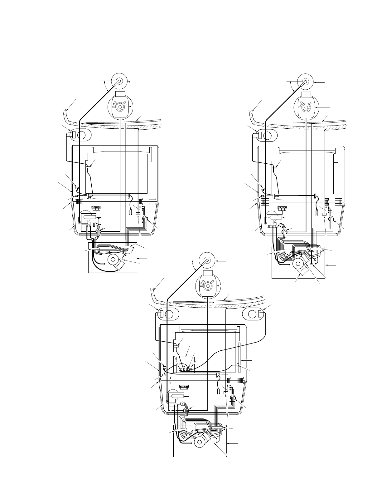
Wire and Lead position Diagram
After servicing, make sure that all wires and leads are placed
in their original position. It is important for the best operation of
the unit.
(Model : A, B, C, D, E) (Model : F, G, H)
Anode Cap
Degaussing Coil
Deflection Yoke
Grounding Wire
Speaker-R
White
Red
P1002
VCR Main
C.B.A.
PK1
PK2
Clamper
Degaussing Coil Connector
Clamper
CRT C.B.A.
P354
Degaussing Coil
45°
(Model : I)
Speaker -R Speaker -L
White
+
Red
Frame
Anode Cap
Deflection Yoke
Grounding Wire
P4591
TV Main
C.B.A.
Clamper
-
+
+
Speaker-R
VCR Main
C.B.A.
Frame
White
Red
P1002
P4591
TV Main
C.B.A.
Degaussing Coil
+
PK3
Clamper
Clamper
Clamper
45°
Deflection
Yoke
Connector
Flyback
Transformer
Clamper
White
Red
Clamper
PK3
45°
Clamper
Deflection
Yoke
Connector
Flyback
Transformer
Clamper
(Model: G, H) (Model: F)
Anode Cap
Deflection Yoke
Grounding Wire
PK1
PK2
Clamper
Degaussing Coil Connector
Clamper
CRT C.B.A.
P354
P1002
VCR Main
C.B.A.
P4592
Frame
TV Main
C.B.A.
Note:
No lead wires or flat cables should touch
any heating parts or the Heat Sink Plate of
IC451, IC801, or Q551.
Clamper
P4601
PK3
Clamper
Stereo Amp C.B.A.
P4602
P4605
P4604
Deflection
Yoke
Connector
Flyback
Transformer
Clamper
Fig. 6
1-13
Clamper
PK1
PK2
Clamper
Degaussing Coil Connector
Clamper
CRT C.B.A.
P354
TV Stereo C.B.A.
P4301

Cylinder Rotation in STOP mode
The cylinder will continue to rotate for approximately 5 minutes
after the STOP button is pressed in Play mode etc. Eject the
tape in order to stop the cylinder.
Black Screws on the Chassis
Black Screws are used on the Mechanism Chassis to identify
screws that require adjustment.
Variable Voltage Isolation Transformer
An Isolation Transformer should always be used during the
servicing of Combination VCR whose chassis is not isolated
from the AC power line. Use a transformer of adequate power
rating as this protects the technician from accidents resulting in
personal injury from electrical shocks. It will also protect Combination VCR from being damaged by accidental shorting that
may occur during servicing.
Also, when troubleshooting the above type of Power Supply
Circuit, a variable isolation transformer is required in order to
increase the input voltage slowly.
2. Removing the leadless component
Grasp the leadless component body with tweezers and
alternately apply heat to both electrodes. When the solder
on both electrodes is melted, remove the leadless component with a twisting motion.
Note:
a. Do not attempt to lift the component off the board until
the component is completely disconnected from the
board by a twisting action.
b. Be careful not to break the copper foil on the printed
circuit board.
Tweezers
Chip
Soldering Iron
Fig. 7-1
3. Installing the leadless component
a. Presolder the contact points on the circuit board.
Special Note
All integrated circuits and many other semiconductor devices
are electrostatically sensitive and therefore require the special
handling techniques described under the
"ELECTROSTATICALLY SENSITIVE (ES) DEVICES" section
of this service manual.
Replacement Procedure for Leadless (Chip)
Components
The following procedures are recommended for the replacement
of the leadless components used in this unit.
1. Preparation for replacement
a. Soldering Iron
Use a pencil-type soldering iron that uses less than 30
watts.
b. Solder
Eutectic Solder (Tin 63%, Lead 37%) is recommended.
c. Soldering time
Do not apply heat for more than 4 seconds.
d. Preheating
Leadless capacitor must be preheated before
installation. – (266°F ~ 302°F)
(130°C ~150°C) for about two minutes.
Presolder
Soldering Iron
Fig. 7-2
b. Press the part downward with tweezers and solder
both electrodes as shown below.
Tweezers
Soldering Iron
Solder
Fig. 7-3
Note:
Do not glue the replacement leadless component to the
circuit board.
Note:
a. Leadless components must not be reused after
removal.
b. Excessive mechanical stress and rubbing of the
component electrode must be avoided.
1-14
Portion "a"
Top Plate
Tab
Lever
Lever
Hole Hole
Holder Unit
Tab
Slide
Hot Circuit
Primary circuit exists on the Main C.B.A. and TV Main C.B.A.
This circuit is identified as "HOT" on the C.B.A. and in the
Service Manual. Use extreme care to prevent accidental shock
when servicing.
Service Mode
In order to inhibit detection of the Supply & Takeup Photo
Transistors, Reel Sensor, and Cylinder Lock, place a jumper
between TP6001 and GND.
In this mode, Mechanism movement can be confirmed. When
removing Cassette Up Ass'y or loading mecanism manually, it
can be confirmed without a cassette.
To release from this mode, remove the jumper between
TP6001 and GND.
Defeating the Auto Tracking
To defeat the Auto Tracking Function, place the instrument in
the STOP mode and place a jumper between TP6003 and
TP6009 on the Main C.B.A. The tracking will be placed in the
neutral position.
Method for Manual Loading / Unloading of
Mechanism
Turn the Main Cam Gear counterclockwise (for loading) or
clockwise (for unloading) using needlenose pliers etc.
Needlenose Pliers
Main Cam Gear
Load
Unload/Eject
Fig. 8-1
When loading without a cassette, press Portion "a" on both
sides of the Holder Unit of Cassette Up Ass'y so that the Lever
clears Tab and Hole.
How to set Tracking to the Neutral Position
Ejecting the cassette tape and then, reinserting it will reset the
tracking to the Neutral position.
How to reset all Combination VCR Memory
functions
To reset (clear) the select language, channel auto set and set
clock functions to their initial power on condition (power on, no
cassette inserted), hold down the PLAY and REWIND buttons
on the unit together for more than 5 seconds.
Power will shut off.
Fig. 8-2
Model No. Identification Mark
Use Marks shown in the chart below to distinguish the
different models included in this Service Manual.
MODEL
PV-M1327
VV1307
VV1317W
PV-M1347
PV-M1357W
PV-M2037
VV2007
VV2017W
PV-M2047
Not Used
Note:
Refer to Item 5 of Schematic Diagrams and Circuit
Board Layout Notes, for mark "Z."
MARK
A
B
C
D
E
F
G
H
I
Z
1-15

IC, TRANSISTOR AND CHIP PART INFORMATION
E
B
C
C
E
B
R1
R2
E
C
B
14
GENERAL C.B.A./ASS'Y PARTS
1
UPC4570C,
MN3885S,
AN3361SB,
AN3371SB
VCR MAIN C.B.A.
B
E
1
AN5367FB,
AN3475FBP,
MN675058A5P2
C
B
E
R1
B
R2
UN2112(R1=22K, R2=22K),
UN2115
(R1=10K, R2=OPEN)
B
UN2213(R1=47K, R2=47K),
UN2212(R1=22K, R2=22K),
UN2215
(R1=10K, R2=OPEN)
C
E
LC8643125957,
TC4053BP,
24LC01B/PS1
C
C
R1
R2
E
C
B
2SD1458, 2SD636,
2SB641, 2SD2259
1
C1
E
1
AN5265,
AN3809K
E2
B2
C2
B1
E1
B1
IMX1
TV MAIN C.B.A.
E
C
B
2SC2653H
2SC945A, 2SA733,
2SC1473
C2
C1
B2
E1
E2
1
STR30130
E
C
B
C
B
E
2SD601, 2SD601A,
2SB709
2SD1555LBMTV,
2SD2499LBMA
DTA143ES
(R1=47K, R2=OPEN),
DTA144ES
(R1=47K, R2=47K)
1
T4101,
VLTS0304
1
LA7837
ON3131-R.KT
TV STEREO C.B.A.
4
2
1
AN7420
CRT C.B.A.
3
B
2SD2375, 2SC3852,
2SC4533LP.KT,
2SC5130LF608
E
C
B
2SC3063
C
E
1
VCRS0214
HOW TO READ THE IDENTIFICATION MARK OF
CHIP COMPONENTS.
MARKING PART NO. MARKING PART NO.
A 2SB709
N9 MA372J
X1 IMX1
MARKING
C
8C
BE
UN2213
MARKING
C1
B2
X1
E1 B1E2C2
IMX1
6B UN2112
8C UN2213
hfe classification
MARKING
C
A
BE
2SB709
Q
HOW TO READ THE VALUES OF THE
CYLINDRICAL TYPE CHIP COMPONENTS.
The widest color band must be read first for
value.
3rd
2nd
1st
(a) RESISTOR
There are two types (ERD10LLJ... and ERD10TLJ...) of
chip parts.
1) ERD10LLJ : Refer to above type.
2) ERD10TLJ : The narrow color band must be read
If this part is included in the parts list, be sure that the
color band is read properly when servicing.
(b) CAPACITOR
Because of the width of the color bands, the reading
direction cannot be specified. However, the color band
can be read on either side. Be sure to confirm the value
using the schematic diagram.
CAUTION :
Once chip parts are removed, they must not be reused.
Always use a new part when installing a chip part.
first for value.
1-16
DISASSEMBLY/ASSEMBLY
PROCEDURES
DISASSEMBLY/ASSEMBLY
PROCEDURES OF CABINET
Disassembly Flowchart
Perform all disassembly procedures in the order described in
the "Disassembly Flowchart" shown below. When reassembling,
use the reverse procedure.
CAUTION:
Disconnect AC plug before disassembly.
(Model: A, D, E)
1
Swivel Unit
2
Rear Cover
3
VCR Unit
Swivel Unit (Model: A, D, E)
Disassembly Procedure
1. While pushing one of the Locking Tabs (A) outward, pull
that portion of the Swivel Unit free from the unit.
2. Repeat step 1 for other Locking Tabs (A) to remove the
Swivel Unit.
Bottom View
Locking Tabs (A)
1 Swivel Unit
4
CRT Unit
(Model: I)
Stereo Amp C.B.A.5
Top Shield
6
Plate Ass'y
TV Main C.B.A.7
8
VCR Chassis Unit
9
Main C.B.A.
Cassette Up Ass'y
10
11
Mechanism Chassis
Locking Tabs (A)
Fig. D2
Fig. D1
2-1
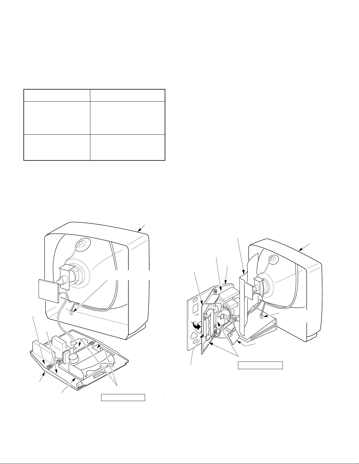
Rear Cover
VCR Unit
Disassembly Procedure
Remove 7 Screws (A). Then, pull the Rear Cover away.
(Model: A, B, C, D, E)
Rear View
Screws (A)
Screws (A)
Fig. D3-1
2 Rear Cover
Disassembly Procedure
1. Discharge the Anode to the CRT Ground. Then, remove the
Anode Cap.
2. Disconnect the Connector P354 from the CRT C.B.A.
3. Carefully pull out the CRT C.B.A. from the CRT Unit.
4. Disconnect the Deflection Yoke Connector and the
Degaussing Coil Connector from the Main C.B.A.
5. (Model : A, B, C, D, E, F, G, H )
Disconnect the Connector P4591 on the Main C.B.A. and
remove the leads from the clampers.
(Model : I )
Disconnect 2 Connectors P4604 and P4605 on the Stereo
Amp C.B.A. and remove the leads from the clampers.
Clampers
TV
P4605
(Model : I)
Anode Cap
CRT C.B.A.
CRT Unit
P354
Stereo Amp
C.B.A.
(Model : I)
(Model: F, G, H, I)
Rear View
Screws (A)
Screws (A)
Fig. D3-2
2 Rear Cover
Clamper
Main
C.B.A.
P4591
(Model : A, B,
C, D, E, F, G, H)
6. (Model: A, B, C, D, E)
Slightly lift up the rear side of the VCR Unit to release Tabs
(B).
(Model: F, G, H, I)
Slightly lift up the rear side of the VCR Unit to release Tabs
(B) and (C).
7. Slide the VCR Unit out as far as it will go.
Then, lift up the VCR Unit to release 3 Guide Tabs (A) and
remove the VCR Unit all the way out from the TV cavity.
P4604
(Model : I)
Deflection
Yoke
Connector
Fig. D4-1
TV Main C.B.A.
Degaussing
Coil Connector
3 VCR Unit
2-2

P4592
Main C.B.A.
P4301
TV Stereo C.B.A.
Clampers (A)
Top Shield
Plate Ass'y
5 Stereo Amp C.B.A.
VCR Unit
Holes (A)
VCR Unit
CRT Unit
Disassembly Procedure
Remove 4 Screws with Washers (A). Then, pull out the CRT
Unit.
Note:
Place the Unit face down on a soft cloth before removing the
CRT Unit.
TV
4 CRT Unit
Guide Tabs (A)
Tabs (B)
Tabs (C)
Bottom view of VCR Unit
Fig. D4-2
Reassembly Notes
1. Installation of VCR Unit
1) When installing the VCR Unit, swing the Cassette DoorLid all the way open until the Cassette Door tab clears
the Opener Lever.
2) Make sure that all guide tabs are aligned properly.
Then, press the VCR unit in.
Cassette Door-Lid
CAUTION
Press
View "A"
Screws with
Washers (A)
Fig. D5
Screws with
Washers (A)
Stereo Amp C.B.A. (Model: I)
Disassembly Procedure
1. Disconnect 2 Connectors P4592 on the Main C.B.A. and
P4301 on the TV Stereo C.B.A.
2. Release 3 Clampers (A) on the TV Stereo C.B.A.
Then, remove the Stereo Amp C.B.A.
View "A"
Cassette Door Tab
Opener Lever
VCR Unit
Cassette Door-Lid
Fig. D6
Fig. D4-3
2-3

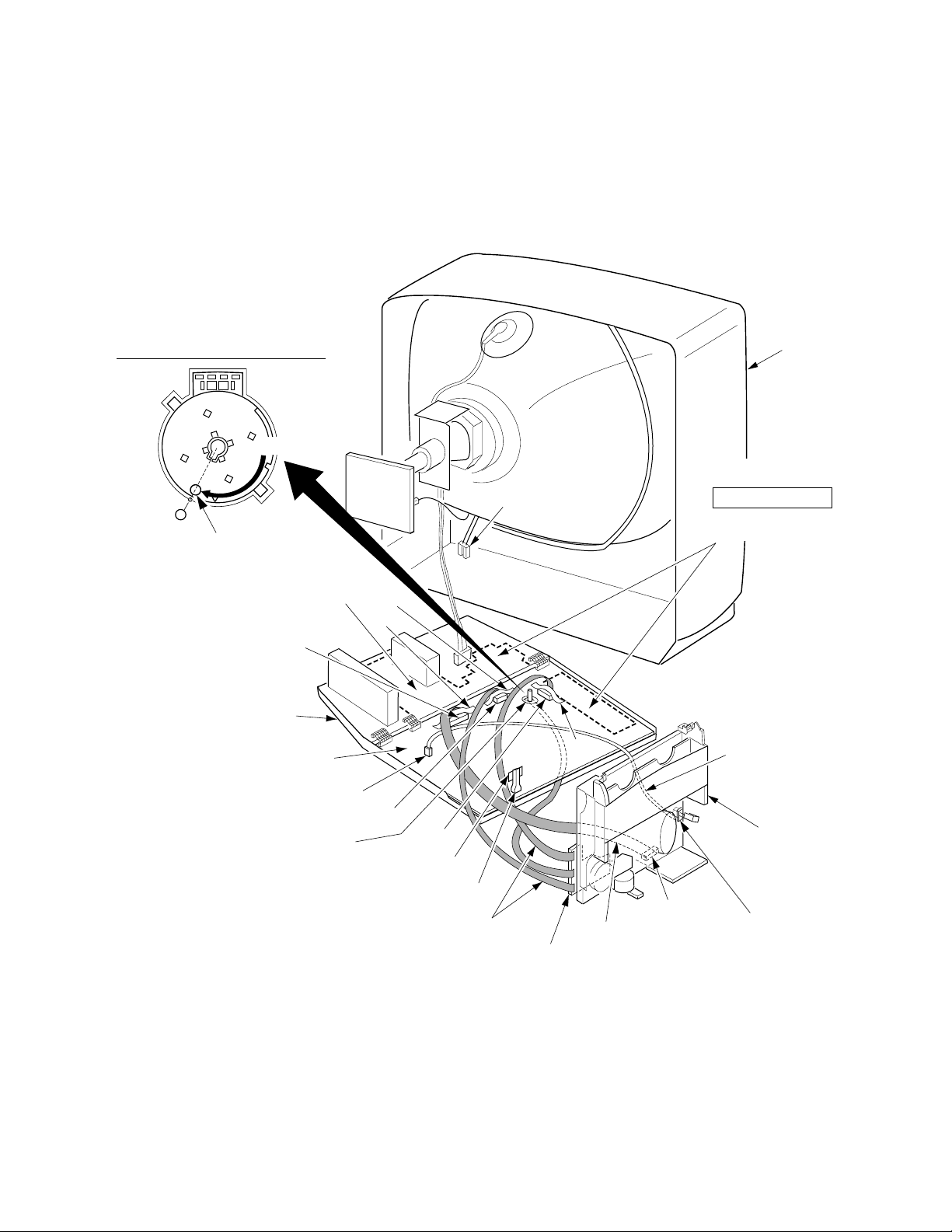
Top Shield Plate Ass'y
TV Main C.B.A.
Disassembly Procedure
1. Release the 2 Clampers (B) on the Top Shield Plate Ass'y
and remove the leads from the clampers.
2. Remove 3 Screws (B). Then, remove the Top Shield Plate
Ass'y.
Clampers (B)
6 Top Shield
Plate Ass'y
Screws (B)
Clamper
Clamper
Fig. D7-1
Disassembly Procedure
1. Disconnect Connector P1002 on the Main C.B.A.
2. Disconnect 3 Connectors PK1, PK2, and PK3 on the TV
Main C.B.A.
Note :
When disconnecting or connecting 3 Connectors PK1,
PK2, and PK3, take extreme care not to break them.
3. Remove the TV Main C.B.A. by releasing 2 Locking Tabs (B)
and A/C Cord from the frame.
PK1
7 TV Main C.B.A.
PK3
Main C.B.A.
PK2
A/C Cord
Reassembly Notes
1. When installing the Top Shield Plate Ass'y, make sure the
2 Clampers (B) on the Cassette Up Ass'y are turned in the
direction shown.
If not, the Top Shield Plate Ass'y cannot be installed.
Clampers (B)
Cassette Up Ass'y
P1002
Locking Tabs (B)
Fig. D8
Fig. D7-2
2-4
P3501
P2531
P2552
Mode Select
SW.
Sensor LED
9 Main C.B.A.
P4001
Mechanism
Chassis Unit
Full Erase Head
Hole
VCR Chassis Unit
Main C.B.A.
Disassembly Procedure
1. Slide the Holder Unit (refer to "Method for Manual Loading/
Unloading of Mechanism" in Service Notes) to remove 2
Screws (C).
2. (Model: A, B, C, D, E)
Remove 3 Screws (D) and Screw (E).
(Model: F, G, H, I)
Remove 2 Screws (D) and Screw (E).
3. Remove 2 Screws with Washers (B).
Screw (D)
(Model: A, B, C, D, E)
Screw with
Washer (B)
Screw (E)
Screw (D)
Screw (D)
"A"
Screws (C)
Screw with
Washer (B)
8 VCR Chassis
Unit
Holder
Unit
Disassembly Procedure
1. Disconnect 4 Connectors of P2531, P2552, P3501 and
P4001.
2. Carefully lift the Mechanism Chassis Unit straight out from
the Main C.B.A.
Note:
Work carefully so as not to break Sensor LED, when lifting
the Mechanism Chassis Unit.
Locking
Frame
Fig. D9
4. While pushing Locking Tab (C) outward, lift the right side of
the Cassette Up Ass'y (Portion "A"). Then, lift the VCR
Chassis Unit out of the Frame.
Note:
Work carefully so as not to break tab.
Tab (C)
Fig. D10-1
Reassembly Notes
1. Make sure that the Mode Select SW. on the Main C.B.A. is
in EJECT position before installing the Mechanism Chassis
Unit onto the Main C.B.A. If not, rotate the Mode Select
SW. until the alignment projection is in the EJECT Position.
Mode Select SW.
2. Be sure to install the Mechanism Chassis Unit straight onto
the Main C.B.A. so that the Sensor LED clears the hole in
the Mechanism Chassis Unit.
3. Be sure that 4 Connectors (P2531, P2552, P3501, and
P4001) are aligned and seated securely.
EJECT Position
Rotate
Alignment
Projection
SERVICE
Fig. D10-2
2-5

Cassette Up Ass'y
Disassembly Procedure
1. Slide the Holder Unit (refer to "Method for Manual Loading/
Unloading of Mechanism" in Service Notes) to remove 2
Screws (F).
2. Remove Screw (G).
3. Unhook Spring (A).
4. Slide the Cassette Up Ass'y towards the front to release
Tab (C). Then, lift it up and remove.
Screw (F)
10 Cassette Up
Ass'y
Tab (C)
Guide Holes
Spring (A)
Pin
Screw (G)
Pin
Pin
Holder
Unit
Guide
Holes
11 Mechanism
Chassis
Screw (F)
Fig. D11
Reassembly Notes
1. Installation of Cassette Up Ass'y
1) Confirm that the 3 pins and Tab (C) under the Cassette
Up Ass'y are in each of the 4 Guide Holes on the
Mechanism Chassis when installing the Cassette Up
Ass'y. Then, slide the Cassette Up Ass'y towards the
back.
2) Tighten 2 Screws (F) and Screw (G).
Be careful not to tighten them too much, or the Cassette
Up Ass'y may be bent outward.
2-6

DISASSEMBLY/ASSEMBLY
PROCEDURES OF MECHANISM
Disassembly Method
This chart indicates Step/Location No. of Parts to be serviced and prior steps to gain access items to be serviced when disassembling.
When reassembling, perform the step(s) in the reverse order.
Step
/Loc.
No.
1
2
3
4
5
6
7
8
9
10
Step/Loc. No.: Order of steps in procedure. Part : Part to be removed or installed. Prior Step(s) : Steps to be completed prior to the current step.
Part Prior Step(s)
Cylinder Unit
Upper Cylinder Unit
Opener Piece
Pinch Arm Unit
Motor Block Ass'y
Audio Control Head Unit
Main Cam Gear
Drive Rack Arm
Main Lever
P5 Arm Unit
------------
------------
------------
3
------------
5
3, 4, 5
3, 4, 5, 7
------------
9
Step
/Loc.
No.
11
12
13
14
15
16
17
18
19
20
Part Prior Step(s)
Main Lever Drive Arm
T Brake Unit
Changing Lever A
T Reel Table
Full Erase Head
Tension Arm Unit
S Spring Arm
S Reel Table
S Brake Arm Unit
Main Lever Guide
3, 4, 5, 7, 8, 9
9
9
9, 12, 13
------------
------------
------------
16, 17
9, 16, 17, 18
9
Step
/Loc.
No.
21
22
23
24
25
26
27
28
29
30
Part Prior Step(s)
Loading Post Base-S Unit
Loading Post Base-T Unit
Capstan Rotor Unit
Capstan Holder Unit
SS Brake Arm Unit
Junction C.B.A.
Capstan Stator Unit
Sub Rotor
PCB Holder
T Loading Arm Unit
16
9, 20
------------
23
------------
------------
23, 25, 26
23, 25, 26, 27
23, 25, 26, 27
------------
Note: When the mechanical parts surrounded by rectangle are removed or replaced, be sure to perform necessary adjustment or alignment
procedures according to the mechanical adjustment procedures section and disassembly/assembly procedures of mechanism section.
Perform all disassembly and alignments procedures in EJECT Position.
Step
/Loc.
No.
S Loading Arm Unit
31
32
Center Clutch Unit
33
Changing Gear Spring
34
Changing Gear
35
Changing Lever-B
36
Idler Arm Unit
Loading Rack
37
Grounding Plate Unit
38
39
FG Head
Part Prior Step(s)
30
------------
32
32, 33
32, 33, 34
32, 33, 34
9, 30
------------
------------
TOP VIEW
Cylinder Unit
1
Audio Control Head Unit
6
Upper Cylinder Unit
2
Full Erase Head
15
Loading Rack
37
Loading Post Base-S Unit
21
Tension Arm Unit
16
S Reel Table
18
S Spring Arm
17
S Brake Arm Unit
19
Loading Post Base-T Unit
22
BOTTOM VIEW
SS Brake Arm Unit
25
PCB Holder
29
Motor Block Ass'y
5
Pinch Arm Unit
4
Main Cam Gear
7
Drive Rack Arm
8
Opener Piece
3
Main Lever Drive Arm
11
P5 Arm Unit
10
Main Lever
9
Capstan Holder Unit
24
T Brake Unit
12
T Reel Table
14
Changing Lever A
13
Grounding Plate Unit
38
Junction C.B.A.
26
FG Head
39
Sub Rotor
28
Capstan Rotor Unit
23
Capstan Stator Unit
27
Capstan Belt
Changing Gear Spring
33
Changing Lever-B
35
Fig. J1
2-7
T Loading Arm Unit
30
S Loading Arm Unit
31
Main Lever Guide
20
Idler Arm Unit
36
Changing Gear
34
Center Clutch Unit
32
Cylinder Unit
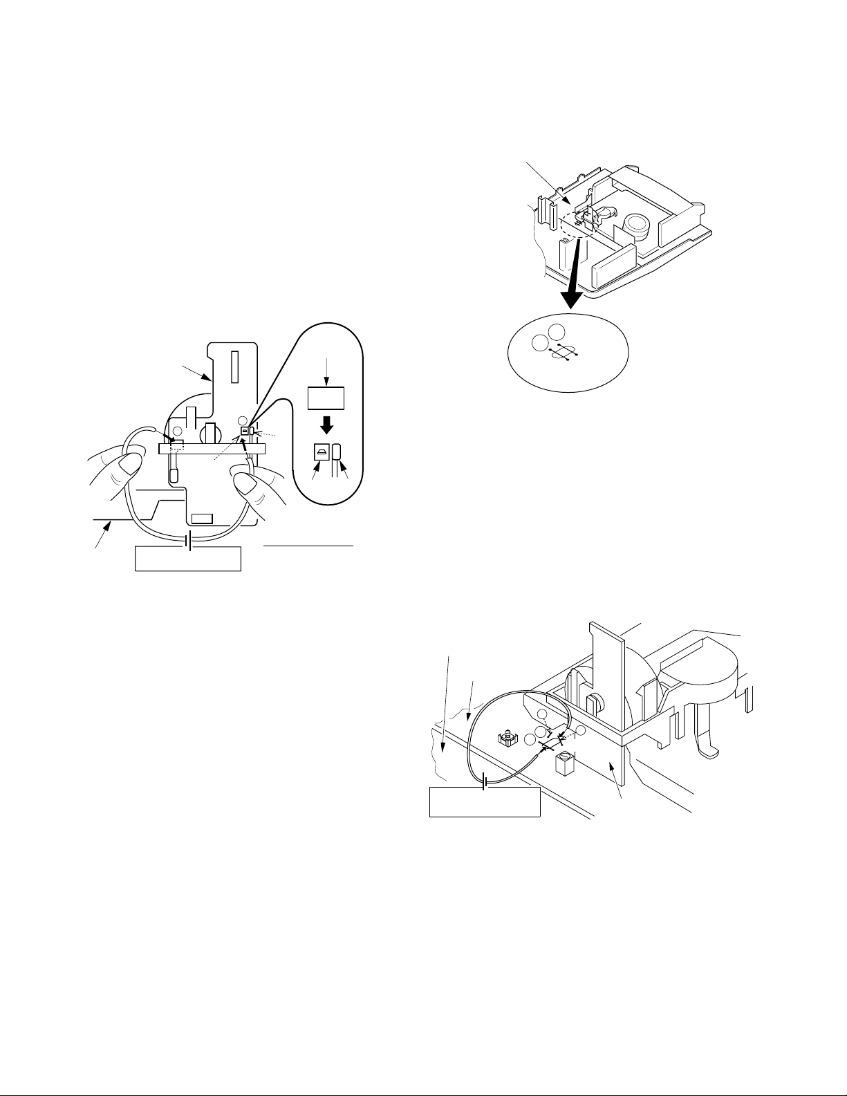
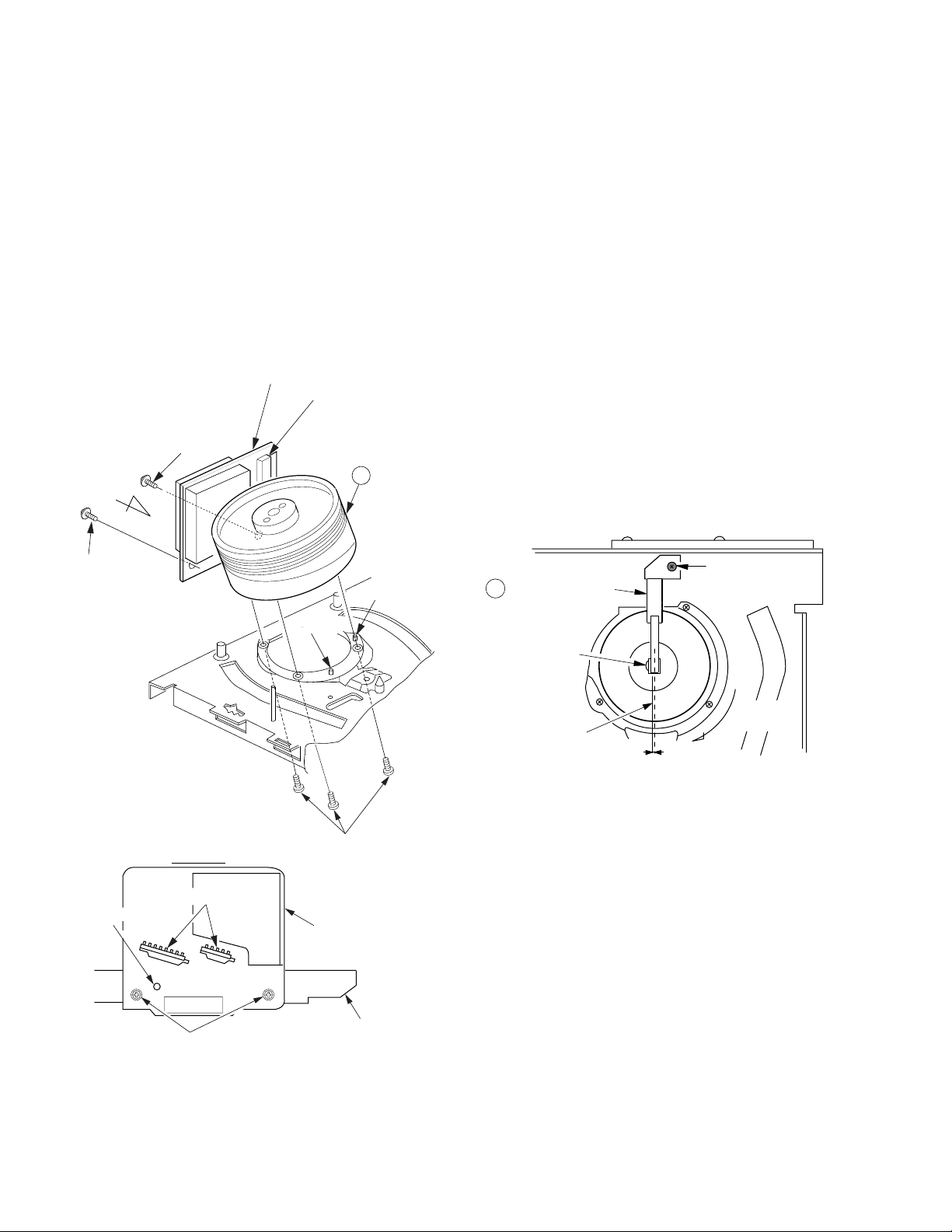
Reassembly Notes
Disassembly Procedure
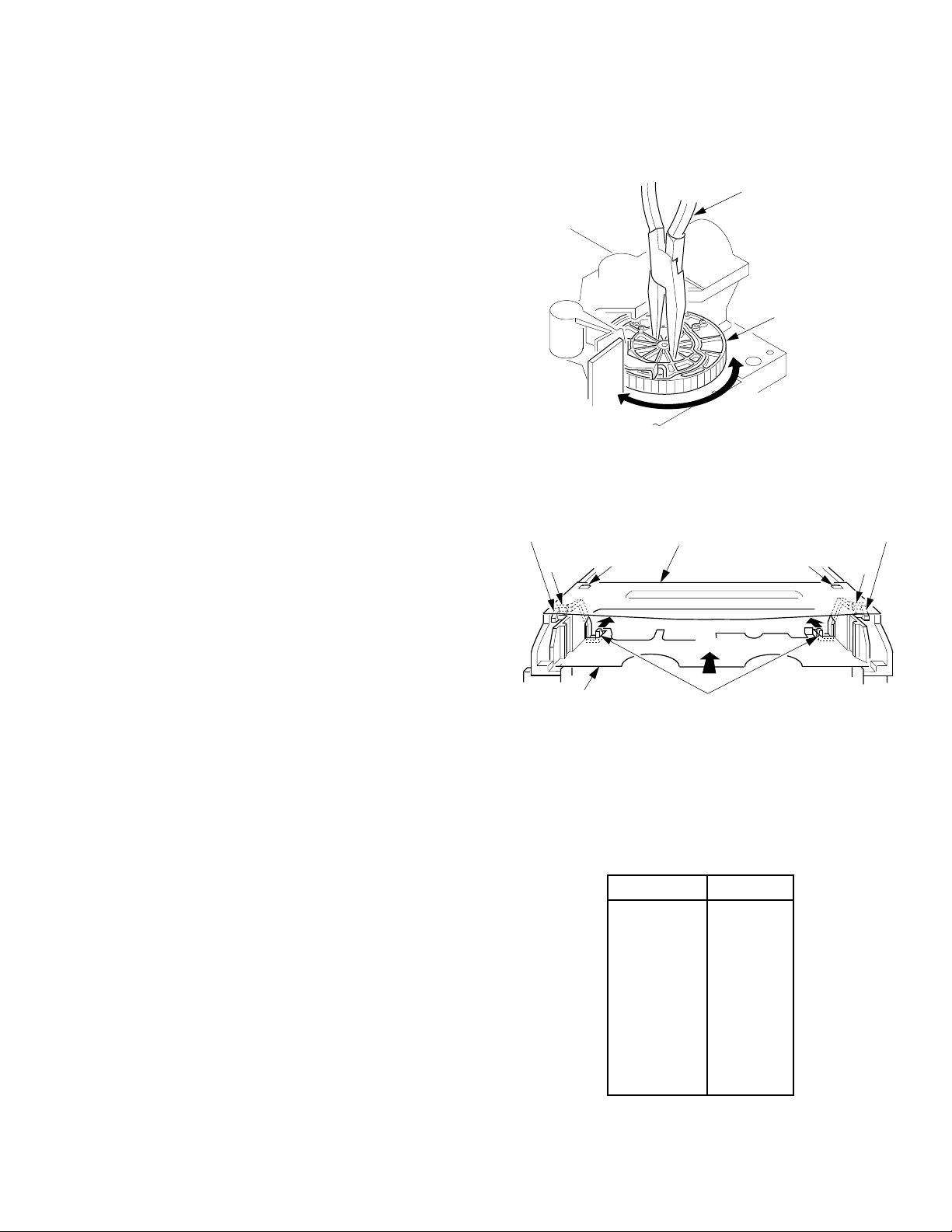
1. Remove 3 Screws (A) and 2 Screws with Washers (A).
Then, lift the Cylinder Unit and the Head Amp C.B.A. out
from the mechanism.
2. Unsolder P3502 and P3503. Then, remove the Head Amp
C.B.A.
Note:
Use extreme care when removing or replacing the Cylinder
Unit. Do not touch the Video Heads during servicing.
CAUTION:
When removing the Cylinder Unit, avoid touching IC2601
on the Head Amp C.B.A. because it is HOT during operation.
Head Amp C.B.A.
IC2601
CAUTION:
Screw with
Washer (A)
View A
Screw with
Washer (A)
HOT during
operation
1 Cylinder
Unit
Guide Pin
Guide Pin
1. Use extreme care when removing or replacing the Cylinder
Unit. Do not touch the Video Heads during servicing.
2. Installation of Cylinder Unit
1) Install the Cylinder Unit so that the 2 holes on the lower
surface of the Cylinder Unit fit over the 2 Guide Pins on
the Cylinder Base and loosely secure it with 3 Screws
(A).
2) Install the Head Amp C.B.A. so that the hole on the
Head Amp C.B.A. lines up with the hole on the chassis
and secure it with 2 Screws with Washers (A).
3) Position the Cylinder Unit so that foil patterns of
connectors (P3502 and P3503) and Head Amp C.B.A.
are aligned, and tighten 3 Screws (A).
4) Solder connectors (P3502 and P3503).
3. Adjustment of Grounding Plate Unit
1) After installing, make sure that the Grounding Plate
Unit, on the bottom side of mechanism chassis, is
positioned on the right side of the Cylinder shaft so that
the center line of the plate is just less than 1.0 mm
measured from the center of the Cylinder shaft.
If required, adjust the plate position by loosening Black
Screw (A).
Never install the Grounding Plate Unit on the left side of
the Cylinder shaft.
Incorrect positioning will cause cylinder buzz.
Black Screw (A)
38 Grounding Plate
Unit
Cylinder Shaft
Through Hole
Screws with Washers (A)
View A
Unsolder
P3502
P3503
Fig. J2-1
Screws (A)
Head Amp
C.B.A.
Chassis
Rotating
Center
1mm
Fig. J2-2
2) After installing, perform the "Tape Interchangeability
Adjustment/Confirmation Procedures."
Direction
2-8
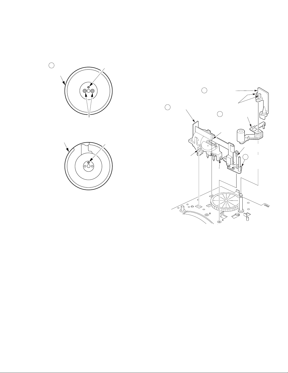
Upper Cylinder Unit
Locking
Tab (B)
Locking Tab (B)
Locking
Tab (B)
Locking Tabs (A)
4 Pinch Arm Unit
3 Opener Piece
5 Motor Block Ass'y
Screw with
Washer (C)
6 Audio
Control
Head Unit
Disassembly Procedure
1. Remove 2 Screws with Washers (B).
2. Carefully lift the Upper Cylinder Unit from the shaft.
2 Upper
Cylinder
Unit
Screws with Washer (B)
Lower
Cylinder
Hole
Indentation
Opener Piece, Pinch Arm Unit, Motor Block
Ass'y, and Audio Control Head Unit
Disassembly Procedure
1. Remove the Opener Piece by pulling it upward while
releasing 2 Locking Tabs (A).
2. Pull up on the Pinch Arm Unit.
3. Release 3 Locking Tabs (B) and remove Screw with
Washer (C). Then, remove the Motor Block Ass'y and
Audio Control Head Unit.
Note:
Use extreme care when removing or replacing the Upper
Cylinder Unit. Do not touch the Video Heads during servicing.
Reassembly Notes
1. Use extreme care when removing or replacing the Cylinder
Unit. Do not touch the Video Heads during servicing.
2. Alignment of Upper Cylinder Unit
1) When installing, make sure that the hole on the Upper
2) After installing, perform the "Tape Interchangeability
Fig. J3
Cylinder is aligned with the indentation on the Lower
Cylinder.
Adjustment/Confirmation Procedures."
Fig. J4
Reassembly Notes
1. Installation of Audio Control Head Unit
1) Install the Audio Control Head Unit before Motor Block
Ass'y.
2) After installing, perform the "Tape Interchangeability
Adjustment/Confirmation Procedures."
2-9

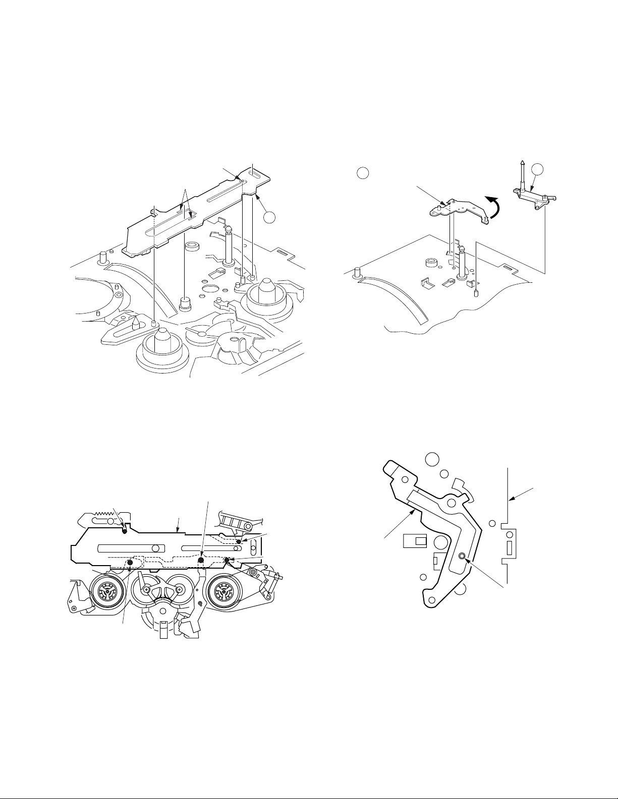
Main Cam Gear and Drive Rack Arm
Reassembly Notes
Disassembly Procedure
1. Remove the Main Cam Push Nut. (Refer to Note.)
2. Pull up on the Main Cam Gear.
3. Turn the Drive Rack Arm fully counterclockwise as shown.
4. Pull up on the Drive Rack Arm.
8 Drive Rack
7 Main Cam
Gear
Main Cam Push Nut
Fig. J5-1
Note:
When removing the Main Cam Push Nut, use a screwdriver
etc.
Shaft of Main Cam Gear
Arm
turn
1. Alignment of Main Cam Gear and Drive Rack Arm
1) Install the Drive Rack Arm so that the hole (A) is aligned
with the hole on chassis as shown (Through hole (A)).
2) Install the Main Cam Gear so that the 2 holes (B)
marked "E" are aligned with the hole on chassis as
shown (Through hole (B)). ("E" indicates the EJECT
position.)
Chassis Hole
Chassis Hole
Main Cam
Gear
2. Installation of Main Cam Gear and Main Cam Push Nut
1) Position the chassis upside down placing a Support
under the Main Cam Gear.
Install the Main Cam Push Nut with Needlenose Pliers
etc. so that it is flush with the chassis.
There may be some slight scratches on the Shaft of
Main Cam Gear, when removing the Main Cam Gear.
In case that the Main Cam Gear can be installed
securely without tottering, it is fine to use the one. If any
tottering, replace a new one.
E
Fig. J5-3
mark
Chassis
Through Holes (B)
Drive Rack Arm
Through Hole (A)
Bottom of Chassis
Main Cam Gear
Fig. J5-2
Main Cam Push Nut
Screwdriver
Press
Needlenose Pliers
Shaft of
Main Cam Gear
Main Cam Push Nut
Bottom of Chassis
Main Cam Gear
support
Fig. J5-4
3. Main Cam Push Nut is not reusable. If removed, install a
new one.
2-10
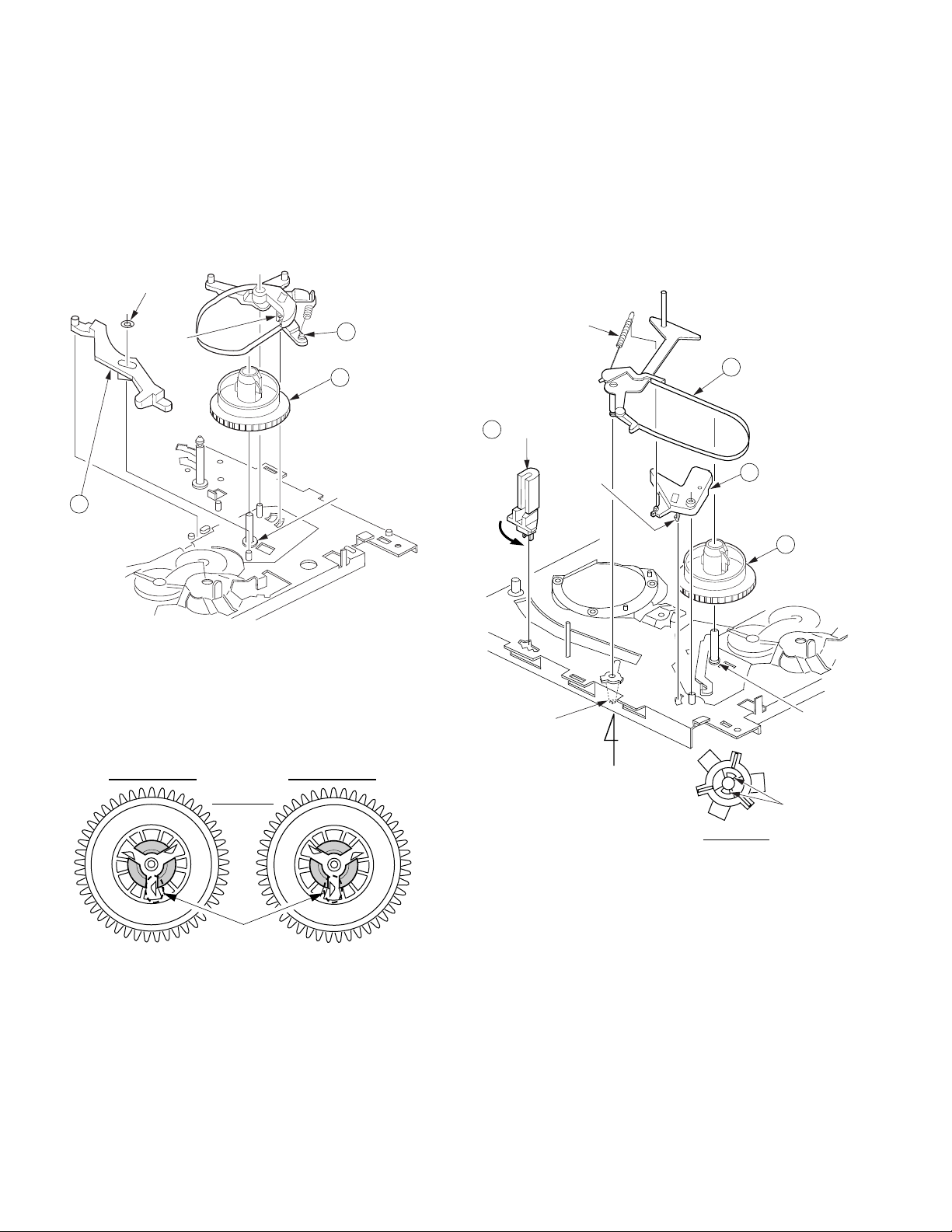
Main Lever
11 Main Lever
Drive Arm
10 P5 Arm
Unit
turn
Main Lever
Drive Arm
Chassis
Through Hole (C)
P5 Arm Unit and Main Lever Drive Arm
Disassembly Procedure
1. Release 2 Locking Tabs (C) and Locking Tab (D). Then,
remove the Main Lever.
Locking Tab (D)
Locking Tabs (C)
9 Main
Lever
Disassembly Procedure
1. Pull up on the P5 Arm Unit.
2. Turn the Main Lever Drive Arm fully counterclockwise as
shown.
3. Pull up on the Main Lever Drive Arm.
Fig. J7-1
Reassembly Notes
1. Confirmation of Main Lever
Fig. J6-1
1) Confirm that bosses and shafts are set properly after
installation of Main Lever.
Loading Rack Shaft
Main Lever
S Brake Arm
Unit Shaft
Changing Lever A Boss
P5 Arm
Unit Boss
T Brake
Unit Boss
Fig. J6-2
Reassembly Notes
1. Alignment of Main Lever Drive Arm
1) Install the Main Lever Drive Arm so that the hole (C) is
aligned with the hole on the Chassis as shown (Through
hole (C)).
Fig. J7-2
2-11
T Brake Unit, Changing Lever A, and T Reel
Table
Full Erase Head, Tension Arm Unit, S Spring
Arm, and S Reel Table
Disassembly Procedure
1. Remove the T Brake Unit while releasing Locking Tab (E)
located under the chassis.
2. Remove Cut Washer (A). Then, pull up on the Changing
Lever A and remove.
3. Pull up on the T Reel Table.
Cut Washer (A)
Locking
Tab (E)
13 Changing
Lever A
12 T Brake
Unit
14 T Reel
Table
Reel Washer
Disassembly Procedure
1. Turn the Full Erase Head fully counterclockwise as shown.
Then remove it.
2. Unhook Spring (A).
3. Remove the Tension Arm Unit by pulling it up while releasing
2 Locking Tabs (F).
4. Remove the S Spring Arm while releasing Locking Tab (G).
5. Pull up on the S Reel Table.
Spring (A)
16 Tension Arm
Unit
15 Full Erase Head
Locking
Tab (G)
turn
17 S Spring Arm
18 S Reel
Table
Fig. J8-1
Reassembly Notes
1. How to distinguish between S Reel Table and T Reel
Table
T Reel TableS Reel Table
Top View
difference
Fig. J8-2
2. Adjustment of T Reel Table
1) After installing, perform the "Reel Table Height
Adjustment Procedures."
3. Be careful not to lose the Reel Washer under the T Reel
Table.
4. Cut Washer (A) is not reusable. If removed, install a new
one.
Locking
Tabs (F)
"A"
View "A"
Fig. J9
Reel
Washer
Locking
Tabs (F)
Reassembly Notes
1. Adjustment of S Reel Table
1) After installing, perform the "Reel Table Height
Adjustment Procedures".
2. Be careful not to lose the Reel Washer under the S Reel
Table.
3. Adjustment of Tension Arm Unit
1) After installing, perform the "Tension Post Adjustment
Procedures."
2-12
 Loading...