

Panasonic VF2 Series, VF Series Instruction Manual
INSTRUCTION MANUAL
Photoelectric Sensor
Multi-voltage Relay Contact Output
VF Series
Terminal Connection Type
DC-voltage Non-contact Output
VF2 Series
Thank you very much for using SUNX products. Please read this Instruction Manual
carefully and thoroughly for the correct and optimum use of this product. Kindly keep
this manual in a convenient place for quick reference.
٨٨Never use this product as a sensing device for personnel protection.
In case of using sensing devices for personnel protection, use
products which meet laws and standards, such as OSHA, ANSI or
WARNING
IEC etc., for personnel protection applicable in each region or
country.
1
SPECIFICATIONS
Multi-voltage relay contact output
Type
Item
Model No. (Note 1)
Sensing range
Hysteresis
Power / Current
consumption
Output
Response time
Ambient temperature
Material
Weight
Accessories
Notes: 1)
The model No. with suffix 'T' stands for the timer incorporated models.
The model No. with suffix 'P' shown on the label affixed to the thru-beam type sensor is
the emitter, 'D' shown on the label is the receiver.
(e.g.) Thru-beam type sensor emitter: VF-M10P, Thru-beam type sensor receiver: VF-M10D
The retroreflective type sensor with polarizing filters may not stably detect specular or
2)
glossy objects through transparent film since light is polarized by the transparent film. For
details, refer to ' RETROREFLECTIVE TYPE SENSOR WITH POLARIZING FILTERS'.
3)
The sensing range for the retroreflective type sensor are specified for the
RF-230 reflector. Further, the sensing range is the possible setting range for the reflector.
The sensor can detect an object less than 0.1m (VF-PRM3, VF2-PRM3: 0.2m) away.
4)
The sensing range of the diffuse reflective type sensor is specified for white non-glossy
paper (200200mm) as the object.
2
CAUTIONS
٨
This product has been developed / produced for inductrial use.
٨
Make sure that the power supply is off while wiring.
٨
Take care that wrong wiring will damage the sensor.
٨
Verify that the supply voltage variation is within the rating.
٨
If power is supplied from a commercial switching regulator, ensure that the frame
ground (F.G.) terminal of the power supply is connected to an actual ground.
٨
In case noise generating equipment (switching regulator, inverter motor, etc.) is
used in the vicinity of this product, connect the frame ground (F.G.) terminal of the
equipment to an actual ground.
٨
Do not run the wires together with high-voltage lines or power lines or put them in
the same raceway. This can cause malfunction due to induction.
٨
Take care that the sensor is not directly exposed to fluorescent lamp from a rapidstarter lamp, a high frequency lighting device or sunlight etc., as it may affect the
sensing performance.
٨
Do not use during the initial transient time (VF series: 200ms, VF2 series: 50ms)
after the power supply is switched on.
٨
The cable length should be up to 100m.
٨
When connecting the induction load for a load,
such as DC relay, the measure against surge
should be done, as shown in the figure right.
٨
This sensor is suitable for indoor use only.
٨
Do not use this sensor in places having excessive vapor, dust, etc., or where it
may come in direct contact with water, or corrosive gas.
٨
Take care that the sensor does not come in direct contact with water, oil, grease,
organic solvents, such as, thinner etc., or strong acid, and alkaline.
٨
The following items are required, as conditions for use of VF series in order to
conform to CE.
The output applied voltage should be the same as the supply voltage of the
sensor.
Be sure to add a short-circuit protection (a fuse or a breaker) to the power sup-
ply input and the output.
Retroreflective
Thru-
beam
VF-M10T
VF-RM5T
0.1 to 5m
10m 10m
(Note 3)
㧙㧙
24to240VAC %or12to240VDC %
Emitter:
3VA or less
Average:
1.5W or less
Receiver:
3VA or less
Average:
1.5W or less
Relay contact 1a
Switching capacity: 250V 1A AC (resistive load)
Electrical life: 500,000 or more switching operations
(switching frequency 3,600 operations/hour)
Mechanical life: 100,000,000 or more switching operations
(switching frequency 36,000 operations/hour)
-10to+60 (No dew condensation or icing allowed), Storage: -20 to +70
Enclosure: PBT, Lens: Acrylic (front surface of retroreflective type sensor with
polarizing filters: Triacetate)
Emitter:
75g approx.
Receiver:
95g approx.
MS-N70 (Sensor mounting bracket): 1 set, Gland and gland washer: 1 set
Gland packing (large / small 1 No. each): 1 set, VF-SKG (Short-circuit metal joint): 1 pc. for the VF series
RF-230 (Reflector): 1 pc. for the retroreflective type sensor
Adjusting screwdriver: 1 pc. for the diffuse reflective type sensor and for sensors with timer functions
2 sets of sensor mounting bracket, gland, gland washer and gland packing
are attached for the thru-beam type sensors.
+10
-
(Average: 1.5W or less)
9
Diffuse reflective
With polarizing
filters˴0QVG
VF-PRM3
VF-D500T
500mm
0.2to3m
(Note 4)
(Note 3)
15%orlessofoperation distance
15
3VA or less
30V 2A DC (resistive load)
IP66 (IEC)Protection
35 to 85% RH, Storage: 35 to 85% RHAmbient humidity
95g approx. 85g approx.
DC-voltage non-contact output
Retroreflective
Thrubeam
VF2-M10
VF-D1000T
1m
(Note 4)
+10
-
15
VF2-RM5
0.1 to 5m
(Note 3)
12 to 24V DCr10%Supply voltage
Emitter:
25mA or less
Receiver:
25mA or less
NPN transistor universal
Maximum sink current: 100mA
Applied voltage: 30V DC or less
PNP open-collector transistor
Maximum source current: 100mA
Emitter:
70g approx.
Receiver:
85g approx.
DC relay
Sensor
output
With polarizing
filters˴0QVG
VF2-PRM3
0.2to3m
(Note 3)
45mA or less
3ms or less20ms or less
Diffuse
reflective
VF2-D500
500mm
(Note 4)
10% or less of op-
eration distance
+
-
DC
power
3
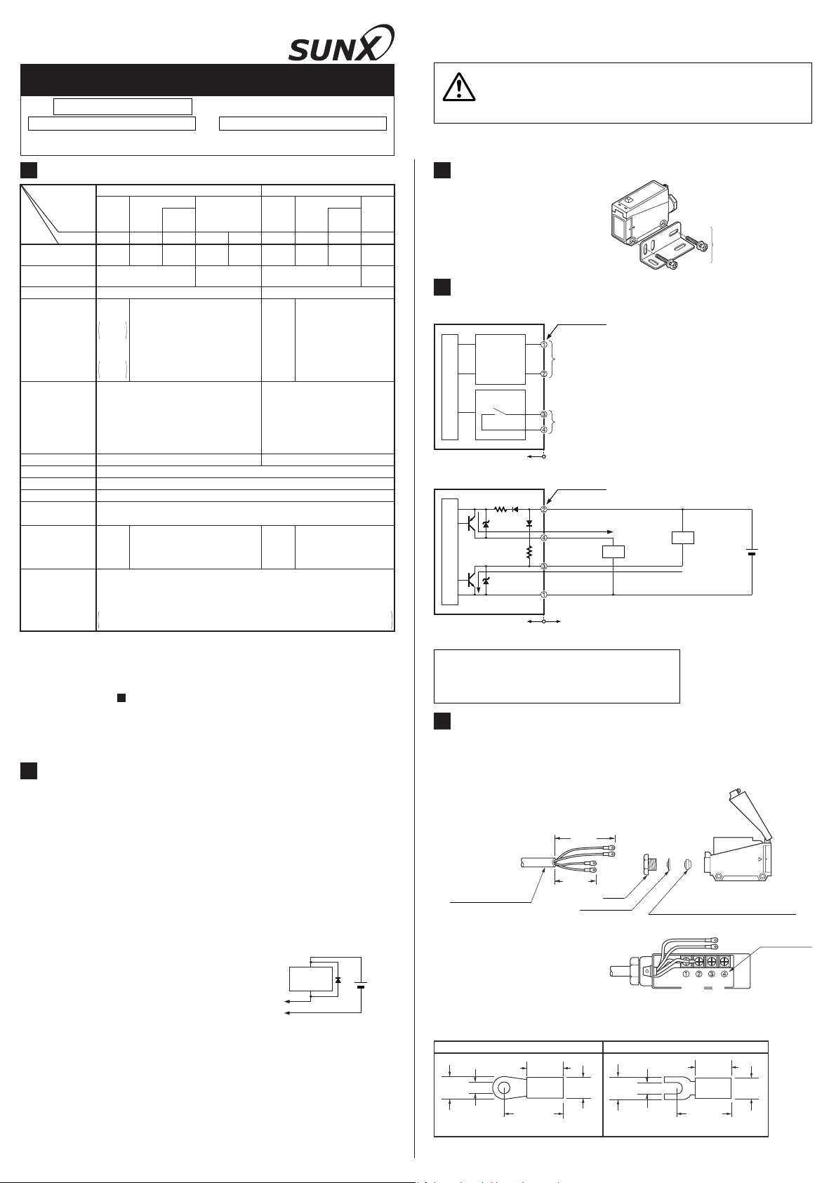
MOUNTING
٨ The tightening torque should be
0.78N㨯m or less.
Sensor mounting bracket
MS-N70
(Accessory)
4
I/O CIRCUIT DIAGRAMS
٨ Multi-voltage relay contact output / VF series
Terminal No.
Power supply
24 to 240V AC %
12 to 240V DC %
Relay contact
(1a)
+10
-
15
or
+10
-
15
Note: The emitter of the thru-beam type sensor
has only two terminals for power supply
(terminal No. Ԙ and ԙ).
Sensor circuit
Multivoltage
circuit
Output relay
Internal circuit
٨ DC-voltage non-contact output / VF2 series
Terminal No.
D110ǡ
+V
D
2
Z
D1
Tr1
4.7kǡ
Tr2
Sensor circuit
Z
D2
Internal circuit Users' circuit
Note: The emitter of the thru-beam type sensor has only two terminals for power supply (terminal
No. Ԙ and ԙ).
Symbols...
5
٨ Prepare the cable end as shown below.
٨
٨
٨
7
or less
Note: Use crimp terminals with insulating sleeves.
D
1: Reverse supply polarity protection diode
2: Reverse current protection diode
D
D1,ZD2: Surge absorption zener diode
Z
r1: PNP output transistor
T
r2: NPN output transistor
T
WIRING
To maintain a watertight performance, the cable should have an outer diameter
between Ǿ6toǾ10mm with a smooth covering material that allows the gland to
be securely tightened, however, the tightening torque of the screw should be of
0.96 to 1.44N㨯m.
Cable
Outer dia: Ǿ6toǾ10mm
Conductor cross section area:
0.25 to 0.75mm
Check the terminal No. first and
connect from the terminal No. Ԙ.
However, the tightening torque of
the screw should be of 0.48N㨯mor
less.
Fix the cover with the mounting
screw.
However, the tightening torque of the screw should be of 0.48 to 0.76N㨯m.
Dimensions of the suitable crimp terminals
Ǿ3.6 or more
Recommended crimp terminal: Nominal size 1.253.5
2
Round type Y-shaped type
19 or less
100mA max.
PNP OUT
NPN OUT
0V
65mm
10 or less
(After crimping)
Load
80mm
Power
}
supply
Gland
Gland washer
7
or less
100mA max.
Output
}
Ǿ3.6ormore
7
or less
Load
Gland packing (2 Nos. enclosed)
Small hole: For Ǿ6toǾ8mm cable
Large hole: For Ǿ8toǾ10mm cable
}
Power
10 or less
19 or less
+
-
}
supply
Output
(Unit: mm)
7
or less
(After crimping)
12 to 24V DC
r10%
Terminal No.
6
MOUNTING THE SHORT-CIRCUIT METAL
JOINT (VF-SKG) (Accessory for VF series)
٨ If the sensor and the load are supplied power from the same power supply, the
number of wires can be reduced by one by using the enclosed short-circuit metal
joint.
Connection example
Terminal No.
Multivoltage
circuit
Output relay
Sensor circuit
Howtomount
Loosen the screws on terminals ԙ and Ԛ.
Mount the short-circuit metal joint VF-SKG on the
terminals as shown on the right.
7
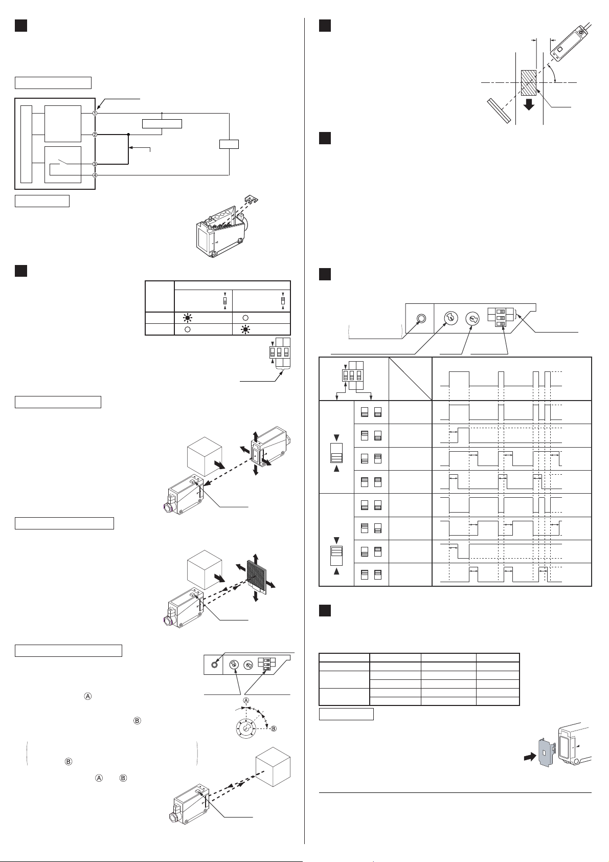
ADJUSTMENTS
٨٨Adjust the sensitivity, observing the
operation indicator (red). However,
since the condition for lighting up of
the indicator depends on the combination of the sensing condition
and the selected operation LightON / Dark-ON, verify if from the table on the light.
For the sensor with timer, be sure to adjust in the state where
the timer function is not operating. As shown in the figure right,
set the timer operation mode switches to '3' and '4' respectively.
٨ Beam alignment
Thru-beam type sensor
Ԙ
Set the operation mode switch to the Light-ON mode position (LIGHT ON side).
ԙ
Placing the emitter and the receiver face to face along a straight line, move the
emitter in the up, down, left and right directions, in order to determine the range
of the light received condition with the
help of the operation indicator (red).
Then, set the emitter at t he center of
this range.
Ԛ
Similarly, adjust for up, down, left and
right angular movement of the emitter.
ԛ
Further, perform the angular adjustment
for the receiver also.
Retroreflective type sensor
Ԙ
Set the operation mode switch to the Light-ON mode position (LIGHT ON side).
ԙ
Placing the sensor and the reflector face to face along a straight line, move the
reflector in the up, down, left and right
directions, in order to determine the
range of the light received condition
with the help of the operation indicator
(red). Then, set the reflector at the center of this range.
Ԛ
Similarly, adjust for up, down, left and
right angular movement of the reflector.
ԛ
Further, perform the angular adjustment
for the sensor also.
٨ Sensitivity adjustment
Diffuse reflective type sensor
Ԙ
Turn the sensitivity adjuster fully counterclockwise to
the minimum sensing range position, MIN.
ԙ
Place an object at the required distance from the sensor, turn the sensitivity adjuster gradually clockwise,
and find out point where the sensor changes to the
light received condition.
Ԛ
Remove the object, turn the sensitivity adjuster further clockwise, and find out point where the sensor
changes to the light received condition again with only the background.
When the sensor does not go to the light received
condition even if the adjuster is fully turned clockwise, point is this extreme point.
ԛ
The optimum position to stably detect objects is the
center point between and .
Power supply
Short-circuited by the shortcircuit metal joint (VF-SKG)
Sensing
condition
Light
Dark
Operation mode switch
Light-ON
(LIGHT ON)
Lights up
Sensing
object
Receiver
Sensing
object
Sensor
Sensor
Load
Dark-ON
(DARK ON)
Timer
operation
mode switch
Operation
indicator
(Red)
Operation
indicator
(Red)
Operation indicator (Red)
MIN MAX
Sensitivity
adjuster
Not
sensing
range
Operation
indicator
(Red)
Short-circuit
metal joint
Lights off
Lights upLights off
12
3
Emitter
Reflector
12
34
MIN MAX
Operation
mode switch
Sensing range
Optimum
position
MAXMIN
Sensing
object
8
RETROREFLECTIVE TYPE SENSOR
٨ Please take care of the following points
when detecting materials having a gloss.
ԘԙMake L, shown in the diagram, sufficient-
ly long.
Install at an angle of 10 to 30 degrees to
the sensing object.
* Retroreflective type sensor with polariz-
ing filters do not need the above adjustment.
9
RETROREFLECTIVE TYPE SENSOR WITH POLARIZING FILTERS
٨ If a shiny object is covered or wrapped with a transparent film, such as those
described below, the retroreflective type sensor with polarizing filters may not be
able to detect it.
In that case, take the following measures given below.
Make L sufficiently
long
Reflector
Sensing
object
L
10 to 30q
Glossy
surface
<Example of sensing objects>
Can wrapped by clear film
Aluminum sheet covered by plastic film
Gold or silver color (glossy) label or wrapping paper
<Measures>
Tilt the sensor with respect to the sensing object while fitting.
Reduce the sensitivity.
Increase the distance between the sensor and the sensing object.
10
TIMER FUNCTION (Only timer incorporated models)
٨ The timer incorporated models have three types of convenient timer functions in
addition to the normal operation.
12
Operation indicator
lights up when the
output is ON.
Sensitivity adjuster
(Diffuse reflective type sensor only)
4
Output
mode
selection
Light-ON
mode
LIGHT ON
Dark-ON
mode
DARK ON
12
3
Timer
mode
4
selection
1
324
1
324
132
132
1
324
1
324
132
132
4
4
4
4
Sensing
condition
Operation
Light-received
normal
operation
Light-received
ON-delay
Light-received
OFF-delay
Light-received
ONE SHOT
Light-interrupted
normal
operation
Light-interrupted
ON-delay
Light-interrupted
OFF-delay
Light-interrupted
ONE SHOT
Timer
adjuster
T
T
T
MIN MAX
Operation
mode switch
T
T
T T T
MIN MAX
T T
34
Timer operation
mode switch
T T
T T
Beamreceived
Beaminterrupted
ON
OFF
ON
OFF
ON
OFF
ON
OFF
ON
OFF
ON
OFF
ON
OFF
ON
OFF
Timer period: T = 0.1 to 5 sec. (variable)
11
SLIT MASK (OPTIONAL)
(Exclusively for thru-beam type sensor)
٨ With the slit mask (OS-VF-غ), the sensor can detect a small object.
However, the sensing range is reduced when the slit mask is mounted.
Slit mask applied Assembly
Without slit mask
OS-VF-6g12
(612mm)
OS-VF-3g6
(36mm)
㧙
Slit on one side
Slit on both sides
Slit on one side
Slit on both sides
Min. sensing object
How to mount
Check the directions of the slit mask and press it to the
lens surface till you feel a click.
SUNX Limited
Head Office
2431-1 Ushiyama-cho, Kasugai-shi, Aichi, 486-0901, Japan
Phone: +81-(0)568-33-7211 FAX: +81-(0)568-33-2631
Overseas Sales Dept.
Phone: +81-(0)568-33-7861 FAX: +81-(0)568-33-8591
Sensing range
10mǾ20mm
4mǾ20mm
3m612mm
2mǾ20mm
1m36mm
URL : sunx.jp/
PRINTED IN CHINA
 Loading...