

Page 1
Operating Instructions
R
DVD Video Camera
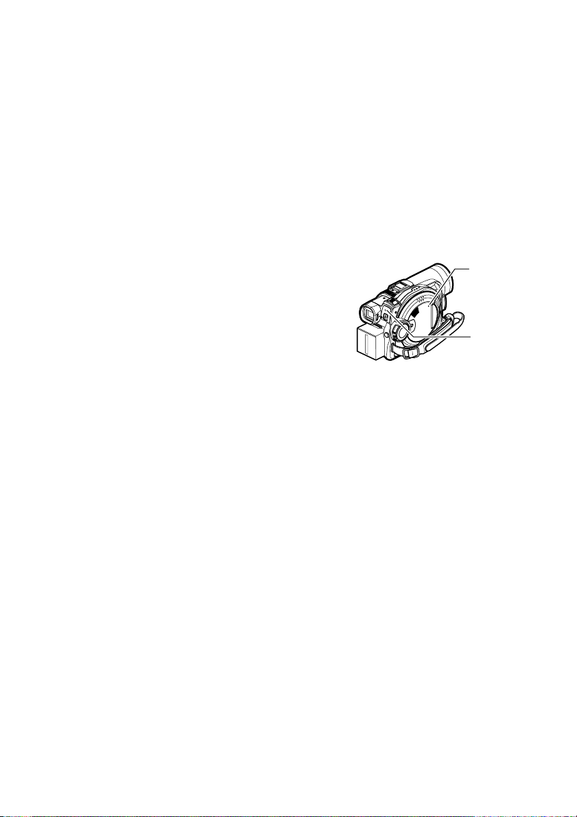
Model No. VDR-M50PP
VDR-M70PP
The illustration shows VDR-M70PP.
Thank you for buying a Panasonic product. Please take the time to become familiar with the operating
instructions and how it is set up. Keep this manual handy for future reference.
Quick Start Guide for Software on page 13.
Be sure to read page 4 before unpacking the provided CD-ROM.
The method for operating the VDR-M50PP is the same as that for VDR-M70PP.
For USA assistance, please call: 1-800-211-PANA(7262) or send e-mail to : consumerproducts@panasonic.com
For Canadian assistance, please call: 1-800-561-5505 or visit us at www.panasonic.ca
VQT0K92-1
H0204HM1034
QR35225
Page 2
Important Information
For Your Safety
The power switch turns the DVD Video Camera on and off, leaving the date/time feature unaffected. If the camera/recorder
is to be left unattended for a long period of time, turn it off .
WARNING : TO PREVENT FIRE OR SHOCK HAZARD, DO NOT
EXPOSE THIS UNIT TO RAIN OR MOISTURE.
WARNING : TO PREVENT FIRE OR SHOCK HAZARD, USE THE
RECOMMENDED ACCESSORIES ONLY.
WARNING: TO PREVENT FIRE OR SHOCK HAZARD, BE
The DVD Video Camera and AC adaptor have the
following caution marks.
CAUTION
RISK OF ELECTRIC
SHOCK
DO NOT OPEN
SURE TO USE THE SPECIFIED AC
ADAPTOR (PV-DAC13).
CAUTION: TO REDUCE THE RISK OF
ELECTRIC SHOCK, DO NOT OPEN.
NO USER-SERVICEABLE PARTS INSIDE.
REFER SERVICING TO QUALIFIED
SERVICE PERSONNEL.
Precautions
WARNING: Many television programs and films are
copyrighted. In certain circumstances, copy-right law
may apply to private in-home videotaping of
copyrighted materials.
The liquid crystal display (LCD) panel is made by
highly precise technology. More than 99.99% of its
picture elements (pixels) are effective, but some (less
than 0.01%) may appear as colored bright dots. This
does not indicate a fault as the LCD panel stretches the
limits of current technology.
Identifications of caution marks
This symbol warns the user that uninsulated
voltage within the unit may have sufficient
magnitude to cause electric shock.
Therefore, it is dangerous to make any kind
of contact with any inside part of this unit.
This symbol alerts the user that important
literature concerning the operation and
maintenance of this unit has been included.
Therefore, it should be read carefully to
avoid any problems.
CLASS 1
LASER PRODUCT
CAUTION
This product contains a laser diode of higher
class than 1. To ensure continued safety, do not
remove any covers or attempt to gain access to
the inside of the product. Refer all servicing to
qualified personnel.
2
Page 3

FCC Note: This equipment has been tested and found to comply with the limits for a Class B digital
device, pursuant to Part 15 of the FCC Rules. These limits are designed to provide reasonable
protection against harmful interference in a residential installation. This equipment generates, uses,
and can radiate radio frequency energy and, if not installed and used in accordance with the
instructions, may cause harmful interference to radio communications. However, there is no guarantee
that interference will not occur in a particular installation. If this equipment does cause harmful
interference to radio or television reception, which can be determined by turning the equipment off and
on, the user is encouraged to tr y to correct the interference by one or more of the following measures:
Reorient or relocate the receiving antenna.
Increase the separation between th e equipment and receiver.
Connect the equipment into an outlet on a circuit different from that to which the receiver is connected.
Consult the dealer or an experienced radio/TV technician for help.
FCC Caution: To assure continued compliance, follow the attached installation instructions and use
only shielded interface cables with ferrite core when connecting to computer or peripheral devices.
Any changes or modifications not expressly approved by the party responsible for compliance could
void the user’s authority to operate this equipment.
Declaration of Conformity
Trade Name: Panasonic
Model No.: VDR-M50PP VDR-M70PP/
Responsible party: Matsushita Electric Corporation of America
Support Contact: Panasonic Consumer Electronics Company
This device complies with Part 15 of the FCC Rules. Operation is subject to the following two
conditions: (1)This device may not cause harmful interference, and (2) this device must accept
any interference received, including interference that may cause undesired operation.
This class B digital apparatus complies with CANADIAN ICES-003.
This Product has a fluorescent lamp that contains a small amount of mercury. It also contains
lead in some components. Disposal of these materials may be regulated in your community
due to environmental considerations. For disposal or recycling information please contact your
local authorities, or the Electronics Industries Alliance: <http://www.eiae.org
One Panasonic Way, Secaucus, NJ 07094
1-800-211-PANA (7262)
.>
U.S.A./CANADA CONSUMERS: ATTENTION:
A lithium ion/polymer battery that is recyclable powers the product
you have purchased. Please call 1-800-8-BATTERY for information
on how to recycle this battery.
Microsoft®, Windows®, Windows® 98, Windows® 98 Second Edition, Windows® Me, Windows® 2000
Professional, Windows
Corporation.
®
Intel
, Pentium® Processor, and Celeron® Processor are registered trademarks of Intel Corporation.
®
IBM
and PC/AT® are registered trademarks of International Business Machines Corporation.
Manufactured under license from Dolby Laboratories.
“Dolby” and the double-D symbol are trademarks of Dolby Laboratories.
Other company names and product names listed are trademarks or brand names belonging to each individual
company.
SD logo is a trademark.
Apparatus Claims of U.S. Patent Nos. 4,631,603, 4,577,216, and 4,819,098, licensed for limited viewing.
This product incorporates copyright protection technology that is protected by method claims of certain
U.S. patents and other intellectual property rights owned by Macrovision Corporation and other rights
owners. Use of this copyright protection technology must be authorized by Macrovision Corporation, and
is intended for home and other limited viewing uses only unless otherwise authorized by Macrovision
Corporation. Reverse engineering or disassembly is prohibited.
®
XP Home Edition and Windows® XP Professional are registered trademarks of Microsoft
3
Page 4

Be sure to read the following before opening the CD-ROM package
This Agreement will take effect at the moment you open the package of the storage device (CD-ROM) provided with this product,
if you agree to the terms herein.
If you do not accept the terms of this Agreement, immedi ately return the unopened package of storage medium and enclosed materials
(printed matter, external package, and all others) to your dealer, or return only the package of storage medium to your dealer.
This License Agreement certifies that you were granted license in the past.
License Agreement
Article 1 Grant of License
Matsushita Electric Industrial Co., Ltd., grants you the following rights for the following products (to be referred to as “This Software”
hereafter) that you have obtained with this Agreement:
(a) You may use This Software only on a single piece of equipment. However, if this equipment cannot be used
because of mechanical problem, you may temporarily use This Software on another piece of equipment.
(b) Although This Software contains several components that can be run on c omputer as independent functions, all
components are licensed as a single product: You may not, by any means, use these components on different
computers at the same time.
Article 2 Copyrights
The copyrights of This Software, attached manual, etc. are owned by the following corporations, and are protected by copyright laws
in Japan and USA, as well as by other intellectual property and international properties:
Name of Software Copyright Owners
USB Driver Hitachi, Ltd.
DVD-RAM Driver Matsushita Electric Industrial Co., Ltd.
DVD-MovieAlbumSE Matsushita Electric Industrial Co., Ltd.
MyDVD Sonic Solutions
Article 3 Other Rights and Limitations
(a) You may not copy This Software or any of the printed materials attached, except for duplications to provide b ack-up or storage.
(b) Use of This Software by third parties is prohibited, whether by transferring, renting, leasing, lending, moving, or any other
measures.
(c) You may not decompile or disassemble this Software.
(d) Duplication and/or distribution of any files on this storage medium for commercial use is prohibited.
Article 4 Quality Assurance
Under no circumstances will Matsushita Electric Industrial Co., Ltd. Hitachi, Ltd., or Sonic Solutions accept any responsibility for
any damages you may incur from using or being unable to use This Software (including, but not limited to, loss of business profit,
interruption of business, loss of business information, or other monetary damages).
Article 5 Termination of Agreement
If you fail to comply with the terms of this Agreement, Matsushita Electric Industrial Co., Ltd. Hitachi, Ltd., and Sonic Solutions
reserve the right to terminate the Agreement. In such a case, you will be obliged to discard all copies of This Software and its
components.
Article 6 Prioritized License Agreement
When some software programs are installed, the license agreements will be displayed (to be referred to as online license agreement).
If the online license agreement conflicts with this Agreement, the online license agreement shall have a priority.
4
Page 5
IMPORTANT SAFEGUARDS
In addition to the careful attention devoted to quality standards in the manufacture of your video product, safety is a major
factor in the design of every instrument. But, safety is your responsibility too.
This page lists important information that will help to assure your enjoyment and proper use of DVD Video Camera and
accessory equipment. Please read it carefully before operating your video product and keep it in a handy place for future
reference.
1 Read and Follow Instructions — All the safety and
INSTALLATION
operating instructions should be read before the video
product is operated. Follow all operating and use
instructions.
2 Retain Instructions — The safety and operating
instructions should be retained for future reference.
3 Heed Warnings — Comply with all warnings on the
video product and in the operating instructions.
4 Power Sources — This video product should be
operated only from the type of power source indicated
on the marking label. If you are not sure of the type of
power supply to your home, consult your video dealer
or local power company. For video products intended
to operate from battery power, or other sources, refer
to the operating instructions.
5 Overloading — Do not overload
wall outlets and extension cords
as this can result in a risk of fire or
electric shock. Overloaded AC
outlets and extension cords are
dangerous, and so are frayed
power cables, damaged or
cracked wire insulation and
broken plugs. They may result in
a shock or fire hazard. Periodically examine the cord
and have it replaced by your service technician if
appearance indicates damage or deteriorated
insulation.
6 Power-Cord Protection — Power-supply cords
should be routed so that they are not likely to be walked
on or pinched by items placed upon or against them,
paying particular attention to cords at plugs,
convenience receptacles, and the point where they
exit from the appliance.
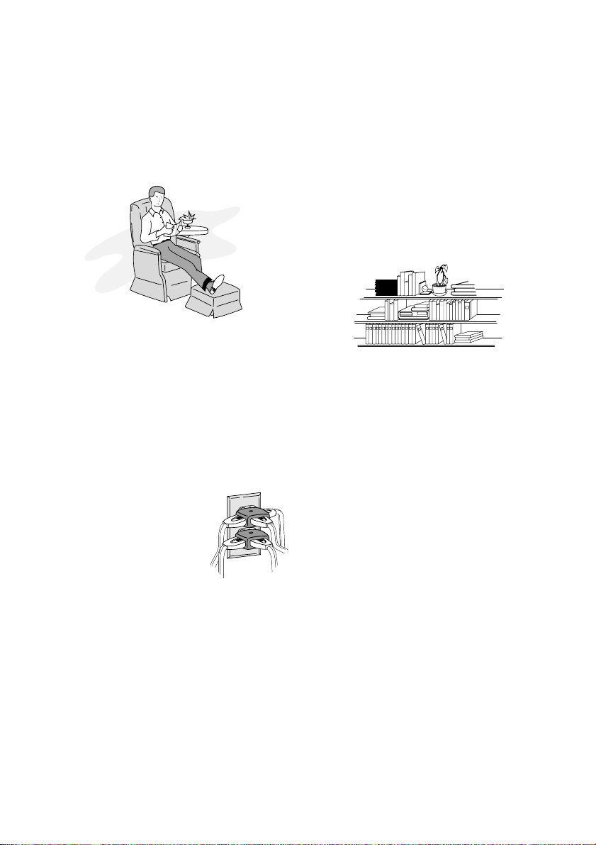
7 Ventilation — Slots and openings in the cabinet are
provided for ventilation to ensure reliable operation of
the video product and to protect it from overheating.
These openings must not be blocked or covered. The
openings should never be blocked by placing the video
product on a bed, sofa, rug, or other similar surface.
This video product should never be placed near or over
a radiator or heat register. This video product should
not be placed in a built-in installation such as a
bookcase or rack unless proper ventilation is provided
or the video product manufacturer's instructions have
been followed.
kawaii koneko
mekoalbum
key to chise
cat book
MOMO
momogatoiredemizubitashi
yohsinarish yohsinarishashin
namemekogaikiteita
nurie
mito
mito
1
mitoniikikata
album
abcdfevcdsz
kabushiki
Zoo Docter
Zoo Docter
tadashiigenkou
mitono
Part 1
Part 2
yakamashii
Why?
tadashiigenkou
auto moter
mother
sasaki akemi
hirayamo akiko
horie youji chikako kimio
igarashi
kuro
kusano
kakurai
oomori matuda
diet
funga funga funga funga
funga funga funga
mame
metsuki
nyanko1midori3okubyo
junkaikun2momo3momo2momo1ebisu2ebisu1key5key4key3key2key1chise5chise4chise3chise2chise
mother
tomodachi
1
123
2
Part2
3
8 Attachments — Do not use attachments unless
recommended by the video product manufacturer as
they may cause hazards.
Caution: Maintain electrical safety. Powerline operated
equipment or accessories connected to this unit should
bear the UL listing mark or CSA certification mark on the
accessory itself and should not have been modified so as
to defeat the safety features. This will help avoid any
potential hazard from electric shock or fire. If in doubt,
contact qualified service personnel.
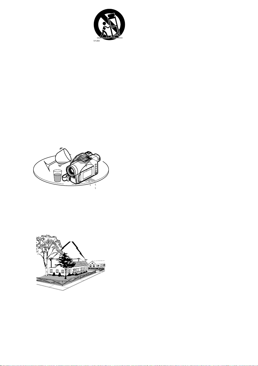
9 Water and Moisture — Do not use this video product
near water — for example, near a bath tub, wash bowl,
kitchen sink, or laundry tub, in a wet basement, or near
a swimming pool, and the like.
10 Accessories — Do not place this video product on an
unstable cart, stand, tripod, bracket, or table. The
video product may fall, causing serious injury to a child
or adult, and serious damage to the appliance. Use
only with a cart, stand, tripod, bracket, or table
recommended by the manufacturer, or sold with the
video product. Any mounting of the product should
follow the manufacturer's instructions, and should use
a mounting accessory recommended by the
manufacturer.
5
Page 6
11 An appliance and cart combination
should be moved with care. Quick
stops, excessive force, and uneven
surfaces may cause the appliance
and cart combination to overturn.
12 Power Lines — An outside antenna system should
not be located in the vicinity of overhead power lines or
other electric light or power circuits, or where it can fall
into such power lines or circuits. When installing an
outside antenna system, extreme care should be
taken to keep from touching or approaching such
power lines or circuits as contact with them might be
fatal. Installing an outdoor antenna can be hazardous
and should be left to a professional antenna installer.
USE
13 Cleaning — Unplug this video product from the wall
outlet before cleaning. Do not use liquid cleaners or
aerosol cleaners. Use a damp cloth for cleaning.
14 Object and Liquid Entry — Never push objects of any
kind into this video product through openings as they
may touch dangerous voltage points or short-out parts
that could result in a fire or electric shock. Never spill
liquid of any kind on the video product.
15 Lightning — For added protection for this video
product during a lightning storm, or when it is left
unattended and unused for long periods of time,
unplug it from the wall outlet and disconnect the
antenna or cable-system. This will prevent damage to
the video product due to lightning and power-line
surges.
16 Servicing — Do not attempt to service this video
product yourself as opening or removing covers may
expose you to dangerous voltage or other hazards.
Refer all servicing to qualified service personnel.
17 Conditions Requiring Service — Unplug this video
SERVICE
product from the wall outlet and refer servicing to
qualified service personnel under the following
conditions.
a. When the power-supply cord or plug is damaged.
b. If liquid has been spilled, or objects have fallen into
the video product.
c. If the video product has been exposed to rain or
water.
d. If the video product does not operate normally by
following the operating instructions. Adjust only
those controls that are covered by the operating
instructions. Improper adjustment of other controls
may result in damage and will often require
extensive work by a qualified technician to restore
the video product to its normal operation.
e. If the video product has been dropped or the
cabinet has been damaged.
f. When the video product exhibits a distinct change
in performance — this indicates a need for service.
18 Replacement Parts — When replacement parts are
required, have the service technician verify that the
replacements he uses have the same safety
characteristics as the original parts. Use of
replacements specified by the video product
manufacturer can prevent fire, electric shock or other
hazards.
19 Safety Check — Upon completion of any service or
repairs to this video product, ask the service
technician to perform safety checks recommended by
the manufacturer to determine that the video product
is in safe operating condition.
20 Heat — The product should be situated away from
heat sources such as radiators, heat registers, stoves,
or other products (including amplifiers) that produce
heat.
6
Page 7

Cautions When Using
Handle the liquid crystal display (LCD) with care:
• The LCD is a very delicate display device: Do not press its surface with force, hit it or prick it with a sharp object.
• If you push the LCD surface, unevenness in display may occur. If unevenness does not disappear, turn the DVD
Video Camera off, wait for a few moments, and then turn it on again.
• Do not place the DVD Video Camera with the open LCD screen down.
• Close the LCD monitor when not using the DVD Video Camera.
Liquid crystal display and viewfinder:
• The LCD screen and viewfinder are the products of highly precise technology. Among the total number of pixels
(approx. 120,000 pixels for LCD monitor and approx. 110,000 pixels for viewfinder), 0.01% or less pixels may
be missing (black dots) or may remain lit as colored dots (red, blue, green). This shows the limitations of the current
technology, and does not indicate a fault that will interfere with recording.
• The LCD screen and viewfinder will be slightly dimmer than usual when the DVD Video Camera is at low
temperature, as in cold areas, or immediately after power is turned on. Normal brightness will be restored when
the temperature inside the DVD Video Camera rises.
Hold the DVD Video Camera correctly:
• Do not hold the DVD Video Camera by the viewfinder or LCD monitor when lifting it: the viewfinder or LCD
monitor could detach and the DVD Video Camera may fall.
Do not subject the DVD Video Camera to impact:
• This DVD Video Camera is a precision machine. Take great care that you do not strike it against a hard object or
let it fall.
• Do not use the DVD Video Camera on a tripod in a place where it is subject to severe vibrations or impact.
No sand or dust!
• Fine sand or dust entering the DVD Video Camera or AC adaptor could cause malfunctions or defects.
No water or oil!
• Water or oil entering the DVD Video Camera or AC adaptor could cause electric shock,
malfunctions or defects.
7
Page 8

Heat on surface of product:
• The surface of the DVD Video Camera will be slightly warm, but this does not indicate a fault.
Screen on connected TV:
• Never leave the disc navigation screen, still image or camera image displayed on your TV to which the DVD Video
Camera is connected: Doing so could result in displayed image retention or phosphor degradation of TV screen.
Be careful of ambient temperature:
• Using the DVD Video Camera in a place where the temperature is over 140ºF (40°C) or under 32ºF (0°C) will result
in abnormal recording/playback.
• Take care that the temperature of this DVD Video Camera, when connected to a PC does not rise excessively
(reference for usage: approx. 30 minutes at about 86ºF (30ºC).
• Do not leave the DVD Video Camera on a beach or in a closed vehicle where the temperature is very high for a
long time: This could cause malfunctions.
Do not point directly at the sun:
• If direct sunlight strikes the lens or viewfinder, the DVD Video Camera could malfunction or a fire could occur.
• Do not leave the DVD Video Camera with the LCD screen exposed to direct sunlight: This could cause
malfunctions.
Do not use the DVD Video Camera near TV or radio:
• This could cause noise to appear on the TV screen or in radio broadcasts.
Do not use the DVD Video Camera near strong radio waves or magnetism:
• If the DVD Video Camera is used near strong radio waves or magnetism, such as near a radio wave tower or electric
appliances, noise could enter video and audio that are being recorded. During playback of normally recorded video
and audio, noise may also be present in picture and sound.
At worst the DVD Video Camera could malfunction.
Do not expose the DVD Video Camera to soot or steam:
• Thick soot or steam could damage the DVD Video Camera case or cause malfunctions.
Do not use the DVD Video Camera near corrosive gas:
• If the DVD Video Camera is used in a place where there is dense exhaust gas generated by gasoline or diesel engines,
or corrosive gas such as hydrogen sulfide, the external or internal terminals could corrode, disabling normal
operation, or the battery connecting terminals could corrode, so that power will not turn on.
Do not use the DVD Video Camera near ultrasonic humidifier:
• Calcium and other chemicals dissolved in water could scatter in the air, and white particles could adhere to the
optical head of the DVD Video Camera, which could cause it to operate abnormally.
Do not expose the DVD Video Camera to insecticide:
• Insecticide entering the DVD Video Camera could dirty the lens in the laser pickup block, and in such a case the
DVD Video Camera might not operate normally. Turn the DVD Video Camera off and cover it with vinyl sheet,
etc. before using insecticide.
Do not use an optional 8 cm CD lens cleaner:
• Cleaning the lens is not necessary when using this DVD Video Camera in the usual way.
• Using 8 cm CD lens cleaner could cause this DVD Video Camera to malfunction.
Do not touch the lens in laser pickup block.
• If you touch the lens in the laser pickup block directly it may cause malfunctions. Laser pickup block is not a
compensable part. Therefore, pay much attention when operating this camera.
8
Page 9
Be careful of moisture condensation:
• When you move the DVD Video Camera between places where the difference in temperatures is great - such as
entering a lodge from a ski slope or going out of a cooled room or vehicle - condensation (vapor in air warmed or
cooled to water droplets) could occur on the lens and/or inside the DVD Video Camera. If condensation occurs,
do not open the cover of disc or card insertion block if possible. If condensation occurs on the lens, wipe it off with
a soft, dry cloth. Even if the external surface of DVD Video Camera has dried, condensation may remain inside:
Turn the DVD Video Camera off and leave it in a dry place for at least 1-2 hours before using it again.
Do not use the DVD Video Camera for a long, uninterrupted period of time:
• This DVD Video Camera cannot be used for a long time continuously as a surveillance camera/monitor. If you use
the DVD Video Camera for a long continuous period of time, the temperature of the DVD Video Camera could
exceed its proper limit and the recording/playback operation could be slowed down: In this case, turn it off and wait
for a while before using it again.
• Take care that the temperature of this DVD Video Camera, when connected to a PC, does not rise excessively
[reference for usage: approx. 30 minutes at about 86ºF (30ºC).]
Do not turn the DVD Video Camera off while the ACCESS/PC indicator or CARD ACCESS
indicator is lit or blinking:
• The ACCESS/PC or CARD ACCESS indicator is lit or blinking to
show that data is being written to disc or card, or being read from it.
At this time, do not do any of the following, so as not to damage the
data:
− Remove battery pack
− Disconnect AC adaptor
− Plug or unplug USB cable
− Remove disc or card
− Subject DVD Video Camera to severe vibrations or impact.
− Forcefully open or close the LCD monitor
If you turn the DVD Video Camera off while the ACCESS/PC or CARD ACCESS indicator is lit or blinking, turn
it on again with the disc or card loaded in it: Repair of the disc or card will be executed automatically (see page 152).
CARD
ACCESS
indicator
ACCESS/PC
indicator
Do not wipe the DVD Video Camera case with benzene or thinner:
• The coating of case could peel off or the case surface could deteriorate.
• When using a chemical cleaning cloth, follow the instructions.
Also read the instructions attached with optional accessories:
• For optional accessories, observe the cautions and follow instruction manuals attached.
Keep the Memory Card out of reach of children to prevent swallowing.
9
Page 10

Cautions When Storing
Do not leave the DVD Video Camera in a place where the temperature is very high for a
long period of time:
• The temperature inside a closed vehicle or trunk can become very high in a hot season. If you leave the DVD Video
Camera in such a place, it could malfunction or the case could be damaged. Do not expose the DVD Video Camera
to direct sunlight or place it near a heater.
Do not store the DVD Video Camera in a place where the humidity is high or in a dusty
place:
• Dust entering the DVD Video Camera could cause malfunctions. If humidity is high, the lens could become moldy,
and the DVD Video Camera could become inoperative. It is recommended that you put the DVD Video Camera
in a box together with a desiccant when storing it in a closet, etc.
Do not store the DVD Video Camera in a place subject to strong magnetism or intense
vibrations:
• This could cause malfunctions.
Detach the battery pack from the DVD Video Camera and store it in a cool place:
• Leaving the battery pack attached or storing it at high temperature could shorten its life.
Suggestions and Restrictions
Make a trial recording:
• Always make a trial recording before doing actual recording to make sure that recording is normal.
Data that have not been stored normally because of a defect in the DVD Video Camera cannot be restored.
It is recommended that you use a DVD-RAM disc from which recorded contents can be deleted for trial recording.
Do not use the DVD Video Camera for professional applications:
• This DVD Video Camera is designed and produced for home-use recording and playback.
The recorded contents cannot be compensated for:
• Panasonic cannot compensate for any damages caused when recording is not made normally or recorded contents
cannot be played back because of a defect in the DVD Video Camera, disc or card. Also, Panasonic cannot be
responsible for your recorded video and audio.
• If you or a third party make a mistake when handling this DVD Video Camer a, disc, card, etc., the recorded contents
may be lost. We cannot be responsible for compensation for damage due to loss of recorded contents.
Copyright:
• Data recorded on the disc or card in this DVD Video Camera using other digital/analog media or devices are
protected by the copyright act and cannot be used without permission of the owner of copyright, except for personal
enjoyment. Be aware that recording is restricted for some demonstrations, performances and exhibitions, even for
personal enjoyment.
10
Page 11

Read This First
To guide you, we've included the following six chapters.
• The section on “Setups” explains how to set up the
DVD Video Camera, battery pack, and set the date/
time.
• The section on “Basic Techniques” explains the basic
operation of this DVD Video Camera-recording of
movies, still images, external input, and playback of
recorded images.
• The section on “Advanced Techniques” explains
settings on this DVD Video Camera for more
advanced usage.
• The section on “Disc Navigation” explains editing
with Disc Navigation: Refer to this section when
finalizing DVD-R disc and initializing DVD-RAM
disc.
• The section on “Installing Software” explains the
contents of provided CD-ROM and how to install the
included software.
• “Subsidiary Information” includes an introduction to
products sold separately, proper cleaning, and
troubleshooting.
With this DVD Video Camera you can view the picture being recorded or the playback picture on the LCD monitor or
in the viewfinder. Opening or closing the LCD monitor switches the picture to appear on the LCD monitor or in the
viewfinder. The following text describes operation assuming that the viewfinder is used as a monitor device.
We want this manual to be as helpful as possible,
so it includes two easy ways to find the information
you need:
• A quick index for the information you use most often
(this page).
• A detailed table of contents directing you to specific
information quickly (see pages 15-17).
Get to know your DVD Video Camera by using this
manual, and get to know Panasonic. We appreciate
your business.
Quick Index
Available Discs................................................. 28
Recording Movie.............................................. 51
Playing Back.................................................... 59
Connecting to a TV.......................................... 69
Functions Available with Disc Navigation ........ 99
Installing Software ......................................... 130
About This Manual
lDisplays in this manual
Understand that the displays in the manual may not appear exactly as those you will actually see in the viewfinder
or on the LCD screen.
lNotation of cancel button
Press the stop/cancel button to stop your operation midway, or return the menu screen to the preceding one. The
expression “press the g button” will be used in this text.
l1 , 2 and 3 marks beside headings
Some functions of this DVD Video Camera are unavailable with disc or card. Refer to the marks at right above each
function to identify whether the disc or card is compatible with the function. Refer to these marks and identify the
functions and operation to match the disc or card you use.
lIllustrations in this manual
Although the external appearances of VDR-M50PP and VDR-M70PP are different, the method of operating both
models is identical.
The illustrations of VDR-M70PP are used in this text.
11
Page 12
Introduction
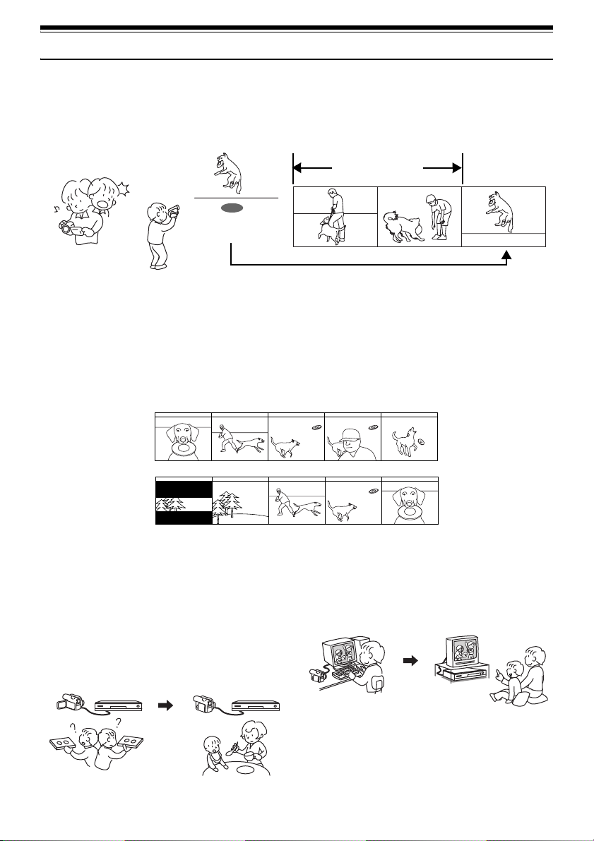
lYou can record even during playback (page 51)
Unlike tape devices, you do not need to search for the recording start position or locate the beginning of a blank
portion.
New recording will not overwrite any previously recorded data.
Recorded scenes
If you stop playback midway and start recording, overwrite will not occur.
lYou can immediately play back desired recorded scenes (page 97)
You do not need to rewind, unlike recorders using tape.
You can select any scene you want and immediately play it back (using Disc Navigation function).
lUse Disc Navigation to create your original movie (page 116)
You can delete unnecessary scenes, move any scenes, etc., and create your original movie work (Play List).
Before editing
After editing
lYou can easily edit scenes (page 77)
Using this DVD Video Camera, you can collect scenes of
your child, for example, on a play list using the Disc
Navigation function and create an original movie: Then
simply play back the play list and dub it on VCR. It is also
easy to make any number of identical tapes.
Until now, you had to
repeatedly press
buttons.
With DVD, you can simply
play back this DVD Video
Camera, and press the
record button on VCR.
12
lCreate original DVDs on PC
(page 141)
You can use a DVD-R disc to create an original DVD,
using the provided software CD-ROM.
The created DVD disc can be played back on a DVD
player, DVD-ROM drive, etc.
Original DVD being
created
Playback of DVD
Page 13
Quick Start Guide for Software
Features
The following software programs are contained on the provided CD-ROM.
Software Feature
USB Driver Install this driver when using the provided USB Cable to connect this
DVD-RAM Driver Install this driver when using stills and images recorded on a DVD-RAM
DVD-MovieAlbumSE By combining DVD-MovieAlbumSE with VDR-M50PP/VDR-M70PP DVD
MyDVD Use this software when creating a DVD-Video disc from motion images
• Confirming the environment of connecting equipment: see page 130.
Installation Guide (see page 130 for details)
1 Installing USB Driver.
• Be sure you do not connect the USB Cable before installing the USB Driver.
• Insert the provided CD-ROM into the PC and “Setup Menu” will activate: you can install the USB Driver from
the “Setup Menu”.
• After the installation completes, the PC can recognize the DVD Video Camera when the DVD Video Camera
and the PC are connected with the USB cable.
2 Install the software (DVD-RAM Driver, MyDVD and DVD-MovieAlbumSE).
• The software can also be installed from the “Setup Menu”.
DVD Video Camera to a PC.
disc on a PC.
Video Camera, it is possible to use playback, recording and editing on
the DVD-RAM disc. It is also possible to transfer extracted data and title
information etc. to MyDVD.
edited using DVD-MovieAlbumSE.
Note:
If the “Setup Menu” does not appear, double-click the CD-ROM drive icon.
Suggestions for using software (see page 141 for details)
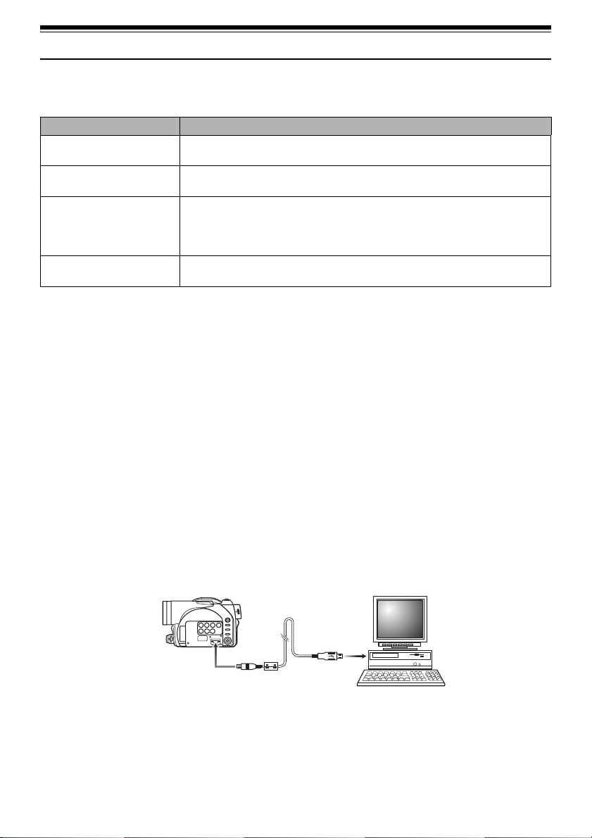
1 Connect this DVD Video Camera to the PC as illustrated below.
• Please ensure a DVD-RAM disc with recorded material is loaded into the DVD Video Camera before
proceeding.
To USB port
2 Edit motion image files using DVD-MovieAlbumSE.
• You can edit motion image files on the DVD-RAM disc.
13
Page 14
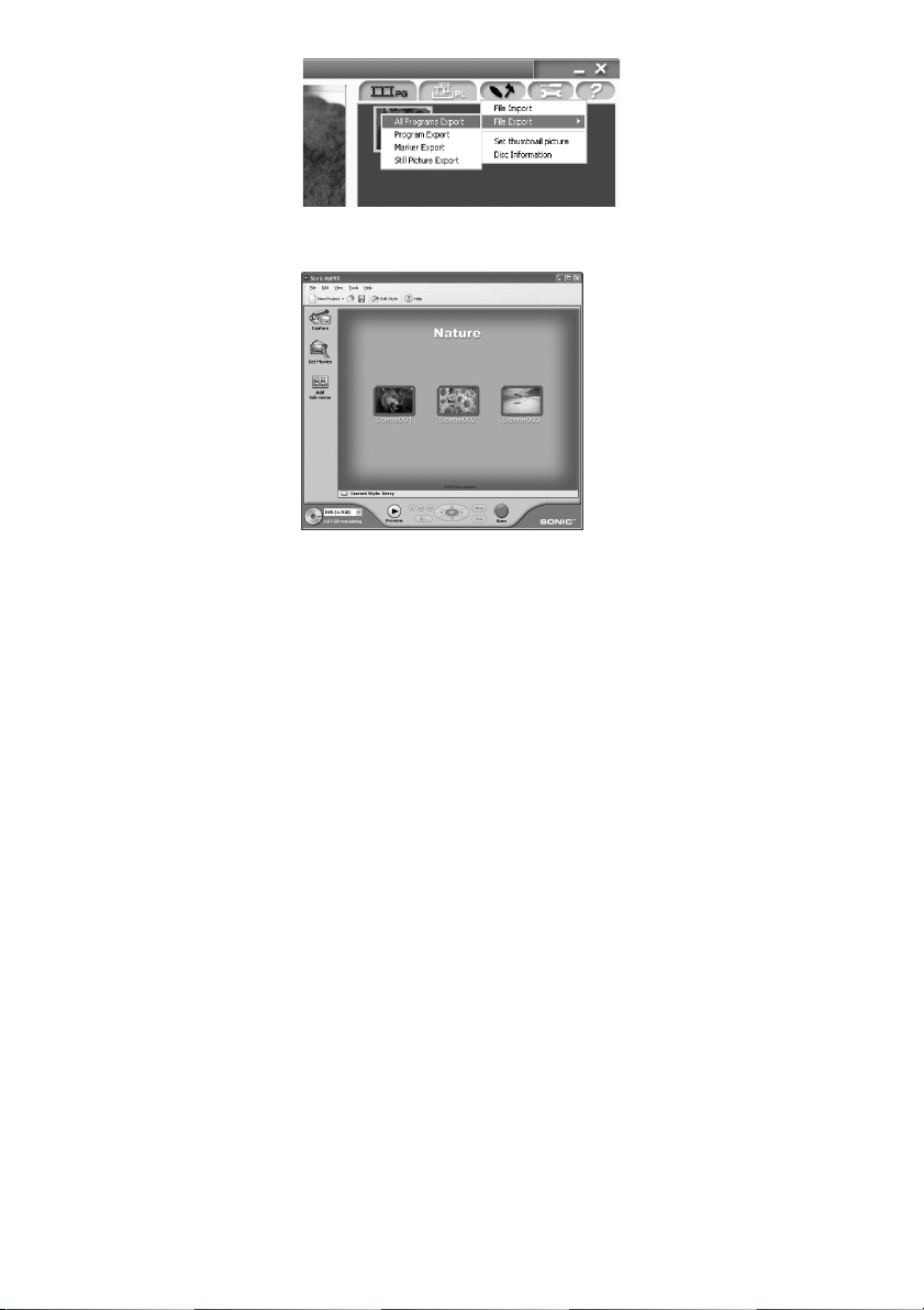
3 Export motion image data to PC using DVD-MovieAlbumSE.
4 MyDVD program will automatically start. (see page 142 for details)
5 Edit motion images and introduce interactive DVD menus using MyDVD Software.
6 Insert a new DVD-R disc into the DVD Video Camera.
• When making an original DVD-R disc using MyDVD software, a message for initialization appears on the
LCD of DVD Video Camera. Select “No” and then follow the instructions on the screen of your PC to make
the original DVD-R disc. Do not perform initialization on DV D Video Camera when using a DVD-R disc with
your computer.
7 Write motion image files to the DVD-R disc with MyDVD.
• Write edited motion images to an 8 cm DVD-R disc in this DVD Video Camera using MyDVD software.
Cautions for use
• When you are making a recording on a new DVD-R disc in your DVD Video Camera, you must initialize the disc
before recording motion images. DVD-RAM disc and Card do not require initialization.
• DVD-R discs are a one time write format; therefore when you write information to the DVD-R disc with
DVD-MovieAlbum or MyDVD, you cannot edit it again.
• When using DVD-MovieAlbum software on Windows
Professional, log on to your PC as Administrator or with a login name equally authorized. If you log on with
a login name other than Administrator, you cannot use DVD-MovieAlbum.
• Set the display resolution to 1024 ~ 768 (16 bits color) when using DVD-MovieAlbum.
Display Settings method as follows:
Select “Start” >> “Settings” (except Windows® XP Home Edition / XP Professional)>> “Control Panel” >> “Display”
and select “Settings” tab on “Display”, and then adjust “Screen Resolution” and “Color quality” to the above.
• MyDVD included in the provided CD-ROM does not contain the slideshows function. Therefore you can not
edit stills on MyDVD.
• Depending on the condition of your PC, it may take a long time to install the software.
®
2000 Professional / XP Home Edition / XP
14
Page 15

Table of Contents
Important Information ........................................ 2
Be sure to read the following before
opening the CD-ROM package ...................... 4
IMPORTANT SAFEGUARDS ........................... 5
Cautions When Using ........................................ 7
Cautions When Storing.................................... 10
Suggestions and Restrictions .......................... 10
Read This First ................................................ 11
About This Manual........................................... 11
Introduction ...................................................... 12
Quick Start Guide for Software ........................ 13
Table of Contents ............................................ 15
Checking Provided Accessories ......................18
Names of Parts ................................................ 19
Setting Up the Battery Pack............................. 23
Charging Battery Pack ......................................... 23
Try to Record and Play Back Using Disc
(Video and Photo)............................................ 24
Try to Record and Play Back Using Card
(Photo) ............................................................. 26
Discs and Cards .............................................. 28
Available Discs .................................................... 28
Information on DVD-R Disc ................................. 29
Examples of Discs that Cannot be
Used on this DVD Video Camera ..................... 29
Handling Discs..................................................... 30
Available Cards ................................................... 31
Storage Capacity of Disc or Card ....................32
Recordable Time of Movie (Video)......................32
Recordable Stills (Photos) on Disc ...................... 33
Recordable Stills (Photos) on Card .....................33
Size and Quality of Photos .................................. 33
Setups
Setting Up the DVD Video Camera ................. 34
Holding DVD Video Camera ................................ 34
Attaching Shoulder Belt ....................................... 35
Attaching Lens Cap .............................................35
Inserting Battery into Remote
Controller .......................................................... 36
Removing Battery from Remote Controller.......... 36
Viewing Subject Through Viewfinder................... 37
Viewing Image on LCD Monitor Screen .............. 38
Closing LCD Monitor ........................................... 39
Setting Date and Time ......................................... 40
Changing Display Format of Date
and Time........................................................... 41
About the Battery Pack .................................... 42
Attaching Battery Pack to DVD Video Camera.... 42
Removing Battery Pack ....................................... 42
Battery Remaining Level Indicator ....................... 44
Efficient Use of Battery Pack ............................... 44
Using DVD Video Camera
with AC adaptor ................................................ 45
Inserting and Removing Disc........................... 46
Inserting Disc....................................................... 46
Removing Disc .................................................... 48
Inserting and Removing Card.......................... 49
Basic Techniques
Basic Operation of DVD Video Camera .......... 50
Turning DVD Video Camera On or Off................ 50
Recording Movie.............................................. 51
Recording Stills................................................ 52
Compensating for Backlight............................. 53
On-Screen Information .................................... 54
Information Display during Recording ................. 54
Zooming........................................................... 57
Macro Recording ................................................. 58
Using Conversion Lens
(Optional-User Provided) .................................. 58
Playing Back.................................................... 59
Playing Back........................................................ 59
Playback from Start of Disc or Card .................... 60
Search Playback of Movie ................................... 60
Frame Advance/Frame Back/Slow Playback of
Movie................................................................ 60
Skip Playback of Movie ....................................... 61
Playing Back Stills............................................... 61
Jumping to Specified Point (Go To) .................... 62
On-Screen Information Display ....................... 63
Information Display during Playback ................... 63
Manually Focusing Subject.............................. 64
Focusing during Recording ................................. 64
Adjusting Exposure Manually .......................... 66
Using Auto Function ........................................ 67
Using External Microphone ............................. 68
Setting Video Flash (Only for VDR-M70PP).... 68
Viewing on TV Screen ..................................... 69
Connecting to a TV.............................................. 69
Viewing on TV Screen......................................... 70
Playback on DVD Video Recorder/Player ....... 71
To Customers Who Have a DVD Video
Recorder with hard disk................................... 71
Playback on DVD Player ................................. 72
Removing from/and Replacing in Round
DVD Holder................................................... 73
How to Remove Disc........................................... 73
Replacing Disc in Round DVD Holder................. 74
When the Hinge of Round DVD
Holder Comes off ............................................. 74
Disc Cleaning ...................................................... 74
Recording (Dubbing) Images........................... 75
Recording (Dubbing) Images from
Other Video Device .......................................... 75
15
Page 16

Recording (Dubbing) Images from
Other Video Cameras ....................................... 76
Recording (Dubbing) Images on Other Video
Devices ............................................................. 77
Advanced Techniques
Understanding Flow of Menus ......................... 78
Setting Up Camera Functions.......................... 80
Selecting Shooting Mode to Match the Subject
(Switching Program AE Mode) ......................... 80
Adjusting Color (White Balance).......................... 81
Using the Electronic Image Stabilizer (EIS)......... 83
Reducing Wind Noise during Recording
(Wind Cut)......................................................... 83
Setting to Wide TV Screen Mode
(Wide) (Only for VDR-M70PP).......................... 84
Setting Up Record Functions........................... 86
Switching Movie Quality (VIDEO Mode).............. 86
Switching Quality of Still Image (Quality) ............. 87
Receiving Image from Another Device
(Input Source) ................................................... 88
Switching External Input Recording Method
(PHOTO Input)................................................. 88
Self Timer ............................................................ 89
Setting OSD Output On or Off
(On-Screen Display) ......................................... 90
LCD Setup ....................................................... 91
Setting Brightness of LCD Screen
(Brightness) ...................................................... 91
Setting Color Density of LCD Screen
(Color Level) .................................................... 91
Initial Settings .................................................. 92
Switching Operating Sound On or Off
(Beep)............................................................... 92
Turning DVD Video Camera Off Automatically
(Power Save) .................................................... 92
Turning Record LED On or Off
(Record LED).................................................... 93
Changing Display Language
(Language) ....................................................... 93
Resetting Menu Settings to Defaults
(Reset) .............................................................. 94
Disc Navigation
Using Disc Navigation...................................... 95
Starting or Terminating Disc Navigation .............. 95
Playing Back from Disc Navigation Screen ......... 97
Selecting Multiple Scenes ................................... 98
Selecting Consecutive Scenes Together............. 98
Disc Navigation Menu...................................... 99
Functions Available with Disc Navigation ............ 99
Understanding Flow of Disc
Navigation Menu............................................. 100
Scene............................................................. 101
Deleting Scenes (Delete) ................................... 101
Changing Images for Thumbnails
(Edit - Thumbnail) ........................................... 103
Playing Back by Skipping Scenes
(Edit - Skip) ..................................................... 104
Arranging Order of Scenes (Edit - Move) .......... 104
Directing Scenes Effectively
(Edit - Fade) ................................................... 105
Combining Multiple Scenes
(Edit - Combine) ............................................. 106
Dividing Movies (Edit - Divide) .......................... 107
Copying Stills on DVD-RAM Disc to Card
(Copy)............................................................. 108
Locking Scenes on Card (Lock) ........................ 109
Designating Scenes to be Printed
(DPOF) ........................................................... 110
Selecting Scenes Using Menu Screen
(Select) ........................................................... 111
Displaying Information Using Menu Screen
(Detail)........................................................... 112
Program......................................................... 113
What is “program”?............................................ 113
Switching to Thumbnail Display of Specific Date
(Switch) .......................................................... 113
Playing Back Program (Play) ............................ 114
Changing Title of Program (Title) ...................... 114
Play List ......................................................... 116
What is “Play List”? ........................................... 116
Creating New Play List (Create) ........................ 116
Switching to Display of Each Play List
(Switch) .......................................................... 117
Playing Back a Play List (Play).......................... 117
Adding Scenes to Play List
(Editing Play List) ........................................... 118
Deleting Scenes from Play List
(Editing Play List) ........................................... 119
Adding Scenes Using Submenu for Editing
(Editing Play List) ........................................... 119
Deleting Scenes Using Submenu for Editing
(Editing Play List) .......................................... 120
Selecting Scenes Using Submenu for Editing
(Editing Play List) ........................................... 120
Arranging Order of Scenes (Move) ................... 121
Changing Title of Play List (Title) ...................... 122
Deleting Play List (Delete)................................. 122
Go To............................................................. 123
Top (End) .......................................................... 123
Disc or Card Management............................. 124
Verifying Remaining Free Space on
Disc or Card (Capacity) .................................. 124
Protecting Disc from Writing
(Protect Disc).................................................. 124
Initializing DVD-RAM Disc or Card
(Format Disc. Format card) ............................ 125
Updating Control Information of DVD-RAM Disc
(Update Control Info.) ..................................... 126
Finalizing DVD-R Disc (Finalize Disc) ............... 127
Other Functions (Others)............................... 128
Displaying Movies or Stills Independently
(Category) ...................................................... 128
Playing Back Scenes Repeatedly
(Repeat Play) ................................................. 128
Slide Show (Continuous Playback of Stills)....... 129
16
Page 17

Installing Software
Compatible PC for use with DVD Video Camera:
VDR-M50PP/VDR-M70PP............................. 130
Operations will not be guaranteed under the
following conditions ..................................... 130
Contents on Provided CD-ROM .................... 131
Installing USB Driver ......................................... 133
Installing DVD-RAM Driver ................................ 135
Installing DVD-MovieAlbumSE .......................... 138
Installing MyDVD ............................................... 140
Creating DVD Video on PC from DVD-RAM
Disc Recorded on DVD Video Camera ....... 141
Uninstalling Software ..................................... 143
Uninstalling USB Driver ..................................... 143
Deleting Other Applications ............................... 144
Supplementary Information
Introduction to Optional Accessories .............145
Video Camera Accessories ............................... 145
Information on Round DVD Holder.................... 146
Cleaning......................................................... 147
Terminology ................................................... 148
Before Requesting Service ............................ 150
Error Messages ............................................. 152
Troubleshooting ............................................. 158
System Reset ................................................ 164
Major Specifications....................................... 165
Request for Service Notice (USA Only)......... 168
Limited Warranty (For USA Customers) ........ 169
Customer Services Directory ......................... 170
Warranty (For Canadian Customers)............. 171
17
Page 18
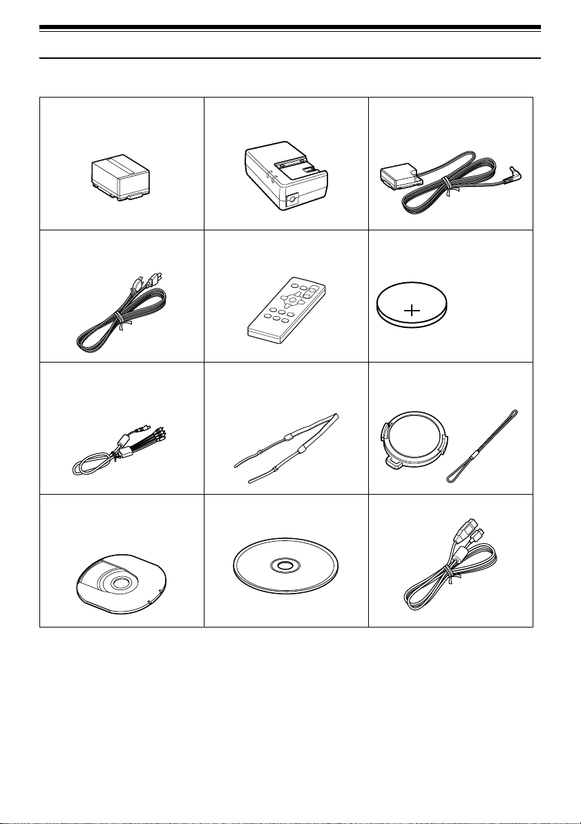
Checking Provided Accessories
Make sure that you found all the following accessories in the package:
Battery Pack (CGA-DU14A):
Portable power supply for this DVD Video
Camera. Charge it before use.
Powe r Ca bl e:
Connect between household AC outlet and
AC adaptor.
AV/S Input/Output Cable: (EW12522)
Used when playing back the DVD Video
Camera picture to a TV screen, or input or
output video from/to another video device.
8 cm DVD-RAM Disc (in Round DVD
Holder):
To record video (movie) on this DVD Video
Camera.
AC Adaptor/Charger (PV-DAC13):
Used to power the DVD Video Camera from
AC outlet, or charge batter y pack.
Remote Controller (VEQ3993):
Use to control the DVD Video Camera from a
distance.
Shoulder Belt:
Attach to the DVD Video Camera to hang it
from shoulder.
Software CD-ROM:
Use this CD-ROM on PC when connecting
the DVD Video Camera to PC.
DC Cord:
When powering the DVD Video Camera from
household AC outlet, use this cord to connect
the DVD Video Camera and AC adaptor.
Button Type Battery (CR2025):
To power the remote controller.
WARNING: Keep
this battery away
from children. If
swallowed, consult
a physician
immediately for
emergency
treatment.
Lens Cap and Lens Cap String:
Attach the lens cap when not recording, to
protect the lens.
USB Cable: (EW12531)
18
Page 19
Names of Parts
123 4
10
11
(Inside the cover)
78
659
N
DISC
NAVIGATIO
SELECT
MENU
u
y
t
i
A/V
MIC
12
13
BATTERY EJECT
(Bottom)
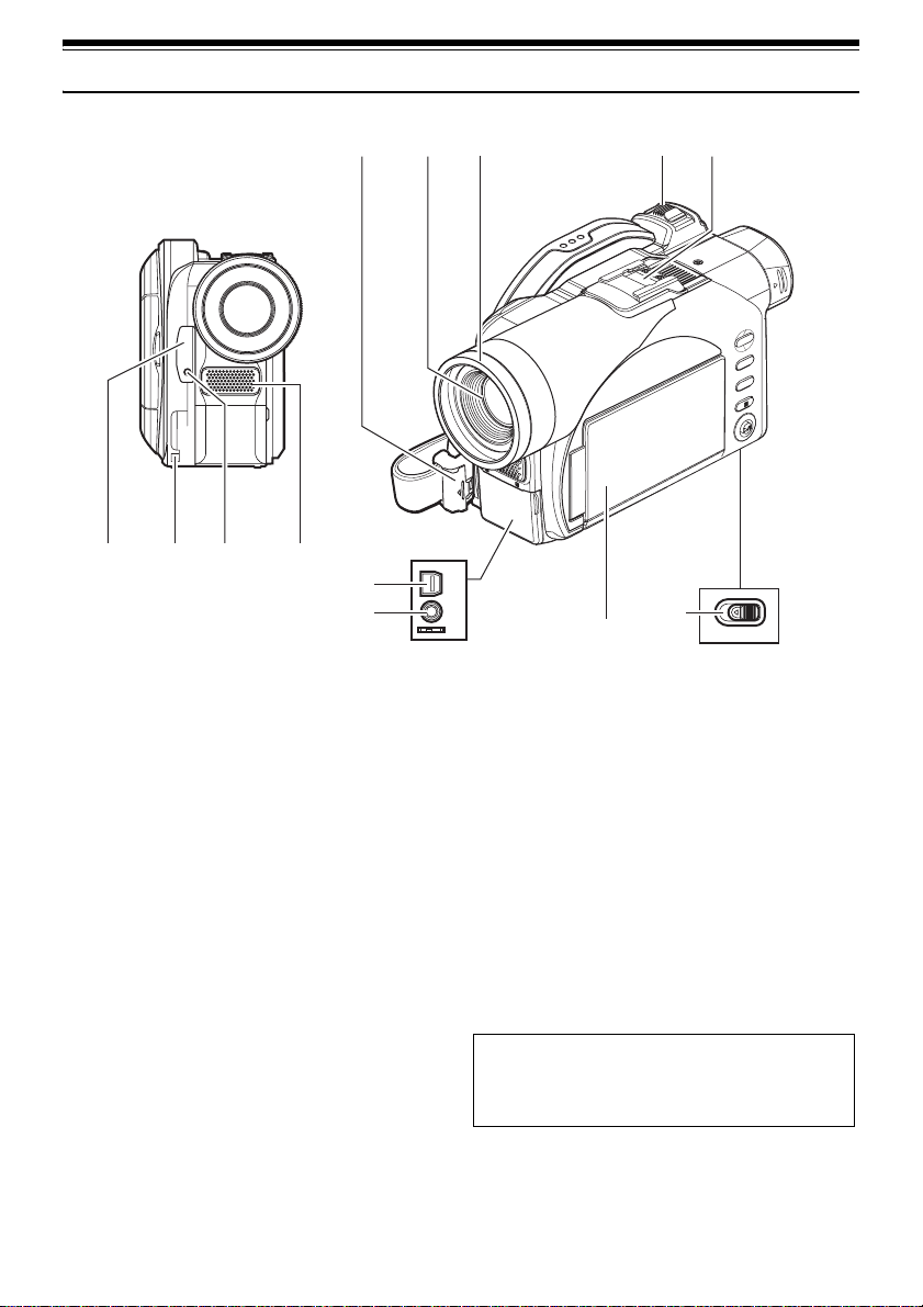
1 Infrared receiver (P. 37)
When the remote controller is used to operate the
DVD Video Camera, this receiver will receive the
infrared signal.
2 Lens cap string attachment hole (P. 35)
3 Recording indicator (P. 93)
The red indicator will light during recording.
4 Internal stereo microphone (P. 51)
5 Lock cover and Lock button (P. 34)
6 Optical 10x zoom lens (VDR-M70PP)
Optical 18× zoom lens (VDR-M50PP)
(P. 57)
7 Lens hood (P. 58)
Always remove this lens hood when using optionaluser provided tele-conversion or wide-conversion
lens.
8 Zoom lever (P. 57)
Push the lever to the T side for telephoto, or to the W
side for wide-angle.
9 Hot shoe (P. 68)
Only for VDR-M70PP:
Attach the optional video flash here.
10 AV input/output jack (P. 69, 75)
11 External microphone jack (P. 68)
12 2.5" type Liquid Crystal Display (LCD)
(inside) (P. 7, 38)
13 BATTERY EJECT switch (P. 42)
The BATTERY EJECT switch is located on the
bottom of this DVD Video Camera: Slide it when
removing the battery pack.
Although the external appearances of VDR-M50PP
and VDR-M70PP are different, the method of
operating both models is identical. VDR-M70PP
illustrations are used in this manual.
19
Page 20
14 15 16 1917
ACCESS/PC
DISC EJECT
18
S
S
E
C
C
A
D
R
A
C
20 21 23 26
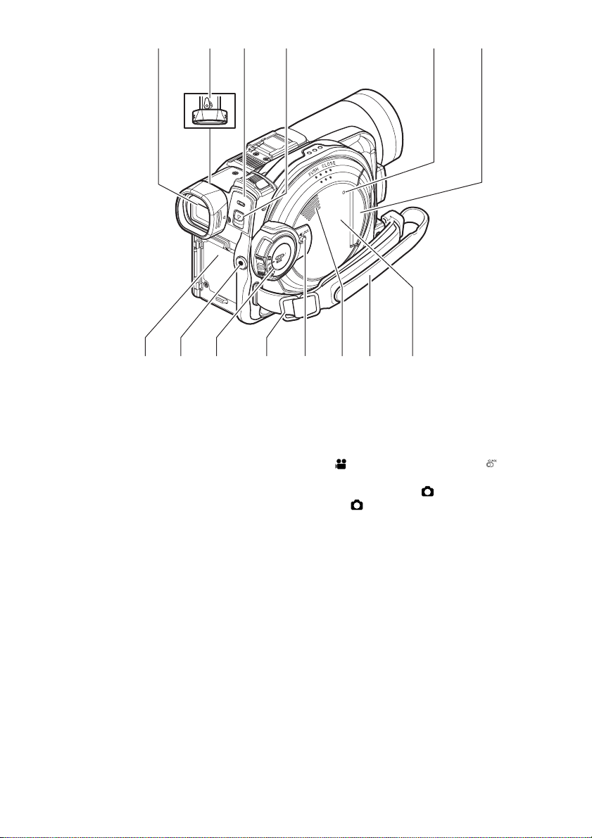
14 Viewfinder (P. 7, 37)
15 Diopter control (P. 37)
To adjust the focus of image appearing in the
viewfinder (Pull out the viewfinder.).
16 ACCESS/PC indicator (P. 9, 51, 52)
Will blink or light when the disc in DVD Video
Camera is accessed (write or read is executed) or the
DVD Video Camera is connected to PC.
17 DISC EJECT lever (P. 46)
Press and release this lever to open the disc guide.
18 CARD ACCESS indicator (P. 9, 52)
19 Card insertion block (P. 49)
20 Battery attachment platform (P. 42)
21 Record (REC) button (P. 51, 52)
2522 24 27
22 Power switch (P. 50, 51, 52)
23 Shoulder belt attachments portion (P. 35)
24 LOCK switch (P. 25, 51)
In mode, set the LOCK switch to (to the left)
to lock the power switch so that it does not
accidentally move to .
From mode, you cannot move the LOCK s witch
to the left to lock the power switch.
25 Speaker (P. 59)
26 Grip Belt (Free Style Grip Belt) (P. 34)
27 Disc insertion block (P. 46)
20
Page 21
28 29 30
AUTO FOCUS
DISPLAY
VOL
32 33
EXPOSURE
31
BACK
LIGHT
AUTO FOCUS
DISPLAY
VOL
EXPOSURE
RESET
BACK
LIGHT
DISC
NAVIGATION
SELECT
MENU
DISC
NAVIGATION
SELECT
MENU
37
38
39
40
34
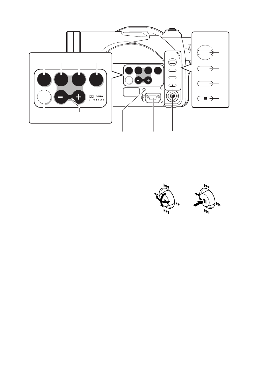
28 AUTO button (P. 67)
To switch the DVD Video Camera to full automatic.
29 FOCUS button (P. 64)
To switch between manual focus and auto-focus.
30 EXPOSURE button (P. 66)
Press this button to adjust the exposure.
31 BACK LIGHT (backlight compensation)
button (P. 53)
Press this button when subject is being illuminated
from behind.
32 DISPLAY (Screen display) button (P. 63)
Press this button to display the details of image being
played back or camera setting status, or to switch the
display off.
33 Volume control buttons (VOL)/ S R buttons
(P. 59, 64, 66)
To adjust the volume of sound from speaker, etc.
34 RESET button (P. 164)
To reset all settings to defaults (status when the DVD
Video Camera was shipped from the factory).
35
36
35 USB port (To PC)
36 Joystick (P. 40, 59, 79)
Move the joystick to select a scene or menu item, and
then press the center (A) to play back the scene,
pause it, or select an option from the menu.
37 DISC NAVIGATION button (P. 95)
38 SELECT button (P. 98, 111)
39 MENU button (P. 40, 79, 101)
Press this button to display the menu for setting
camera functions and Disc Navigation.
The camera menu will appear even if disc is not
loaded.
40 Stop/cancel button (P. 11, 59, 79)
To end playback or cancel menu setting .
21
Page 22
41
42
43
47
48
44
45
46
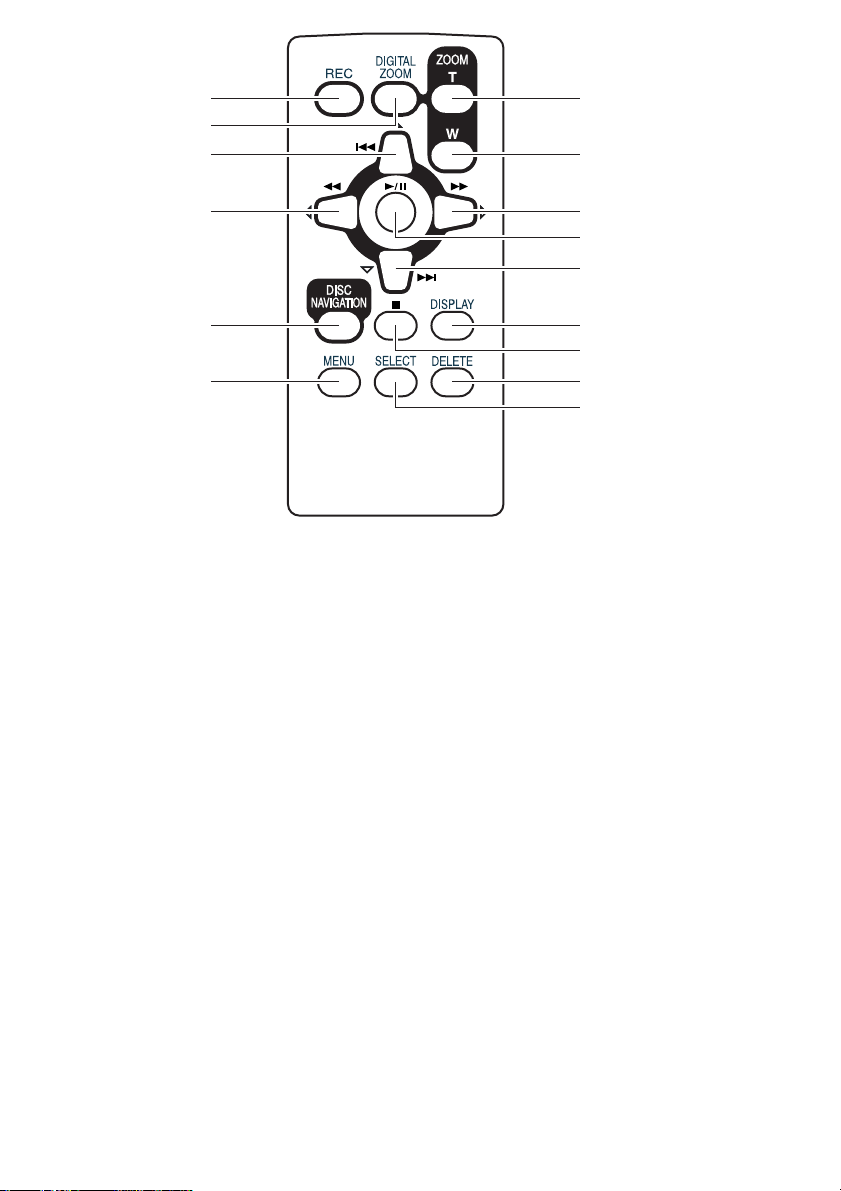
41 REC button (P. 51, 52)
42 DIGITAL ZOOM button (P. 57)
43 Reverse skip button (P. 61)
44 Reverse search button (P. 60)
45 DISC NAVIGATION button (P. 95)
46 MENU button (P. 40, 79, 101)
49
50
51
52
53
54
55
47 ZOOM T button (P. 57)
48 ZOOM W button (P. 57)
49 Forward Search button (P. 60)
50 Play/pause button (P. 59)
51 Forward skip button (P. 61)
52 DISPLAY button (P. 63)
53 Stop button (P. 11, 59, 79)
54 DELETE button (P. 101)
55 SELECT button (P. 98, 111)
* The buttons on remote controller will function the same as those on DVD Video Camera.
22
Page 23
Setting Up the Battery Pack
The CGA-DU14A battery pack provided with this DVD Video Camera has not been charged at purchase
time: Charge it before using the DVD Video Camera.
Note:
• Be sure to use the specified battery pack CGA-DU14A (provided) for the DVD Video Camera: using other batteries could
cause the DVD Video Camera to malfunction, or result in fire.
• Be sure to use the specified AC adaptor to charge the battery pack: using other chargers could cause electric shock
or fire.
• Charge the battery pack at temperatures of 50 - 86°F (10-30°C).
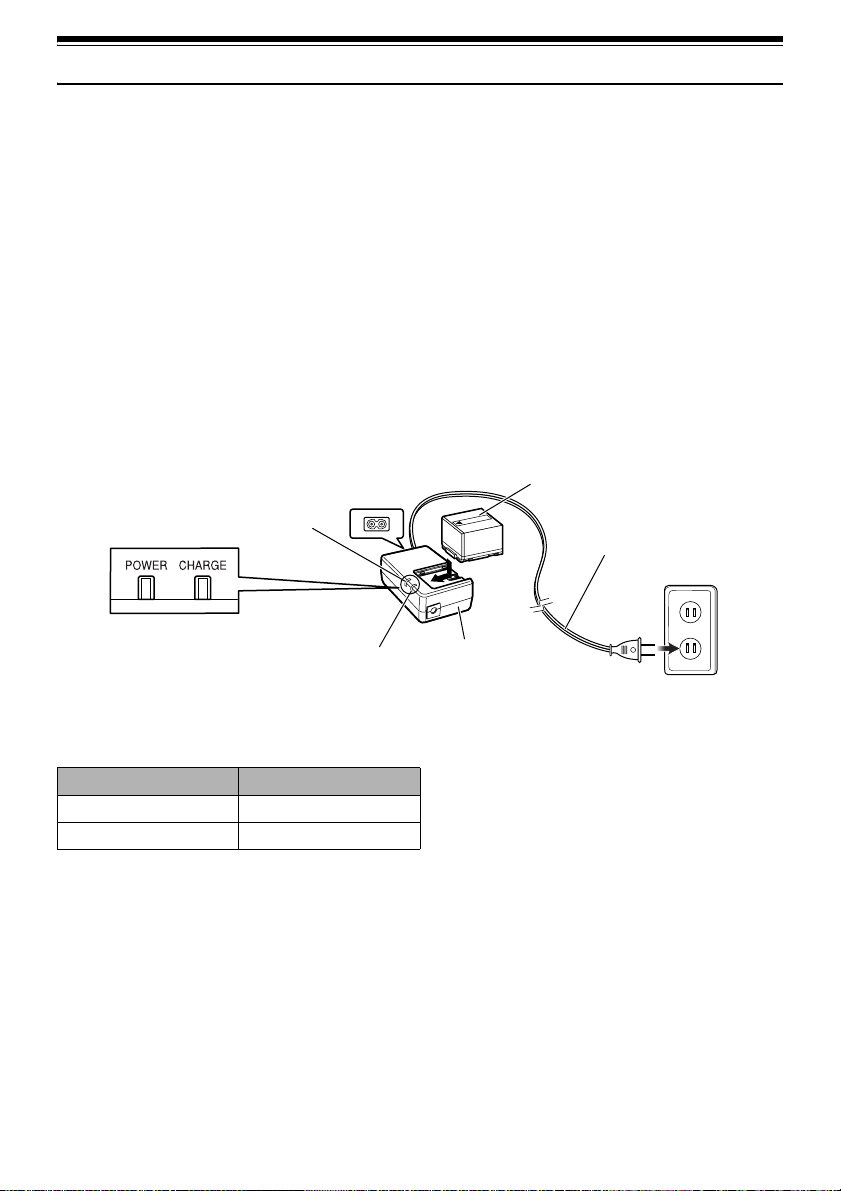
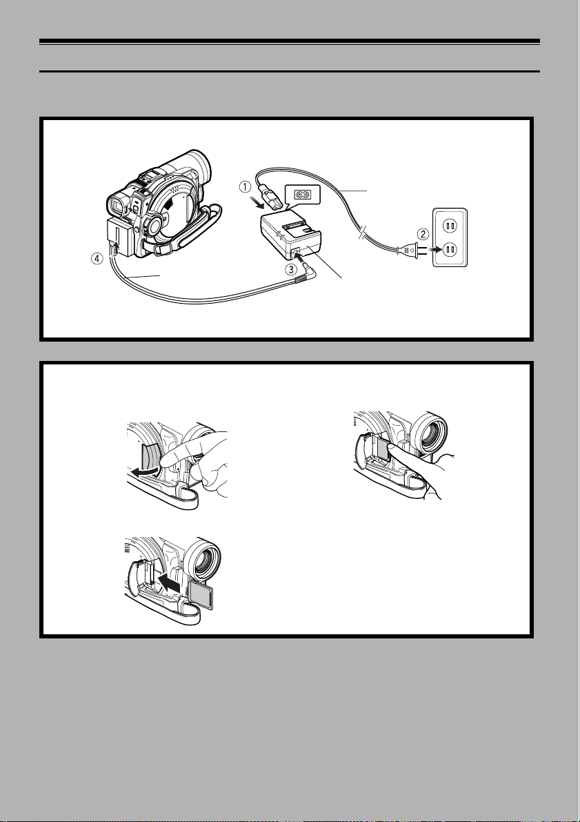
Charging Battery Pack
Use the provided AC adaptor to charge the battery pack.
3 Attach the battery pack to AC adaptor.
1 Connect the power cable to AC adaptor.
2 Plug the power cable into AC outlet.
The CHARGE indicator on AC adaptor will light.
POWER and
CHARGE indicators
POWER
indicator
CHARGE indicator
Note:
When charging a battery pack, unplug the DC cord from the
DC output jack on AC adaptor.
Battery pack
Power cable
AC adaptor
lBattery pack charge status
You can find out the charge status of the battery pack by checking the CHARGE indicator on the AC adaptor:
Charge status CHARGE indicator
During charge Lit
Charge complete Goes out
Note:
• If the CHARGE indicator does not light when the AC
adaptor is plugged into household AC outlet, unplug it
from household AC outlet, wait a few moments, and then
plug it into household AC outlet again. If the CHARGE
indicator still does not light, the AC adaptor may be faulty.
Unplug it from household AC outlet and consult your
dealer.
• See “Troubleshooting” on page 158, when the CHARGE
indicator blinks.
23
Page 24
12
Try to Record and Play Back Using Disc (Video and Photo)
Before You Begin
You can record both videos and photos on DVD-RAM disc; only videos on DVD-R disc.
• It is recommended that you use a DVD-RAM disc for trial recording, since
you can delete the recorded contents (See page 28).
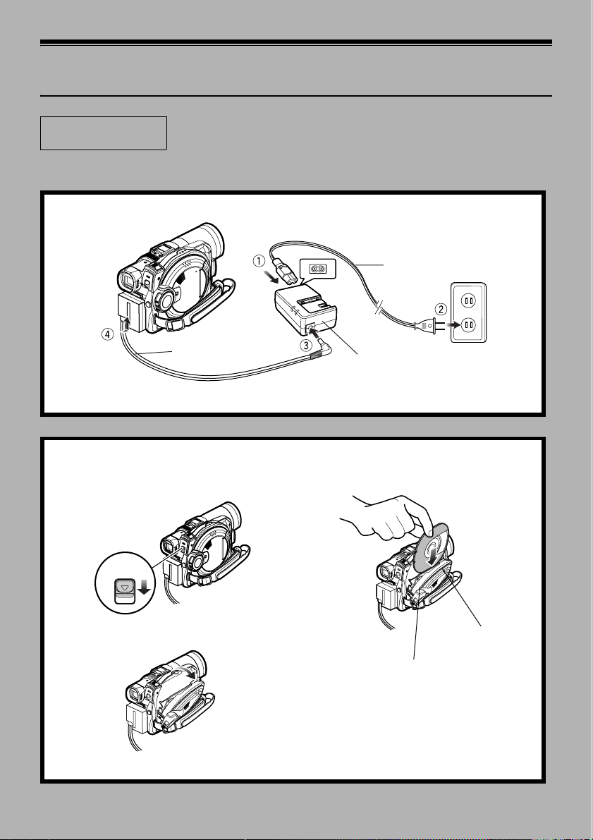
1 Connect power supply (P. 45).
Power cable
DC cord
Connect them in sequence of the digits.
AC adaptor
2 Insert a disc (P. 46).
1. Press down the DISC EJECT lever once and
release it.
3. Insert the disc, in Round DVD Holder, into the disc
guide until it stops.
DISC EJECT
2. Gently open the cover until it stops.
24
Disc cover
PUSH CLOSE
portion
Page 25
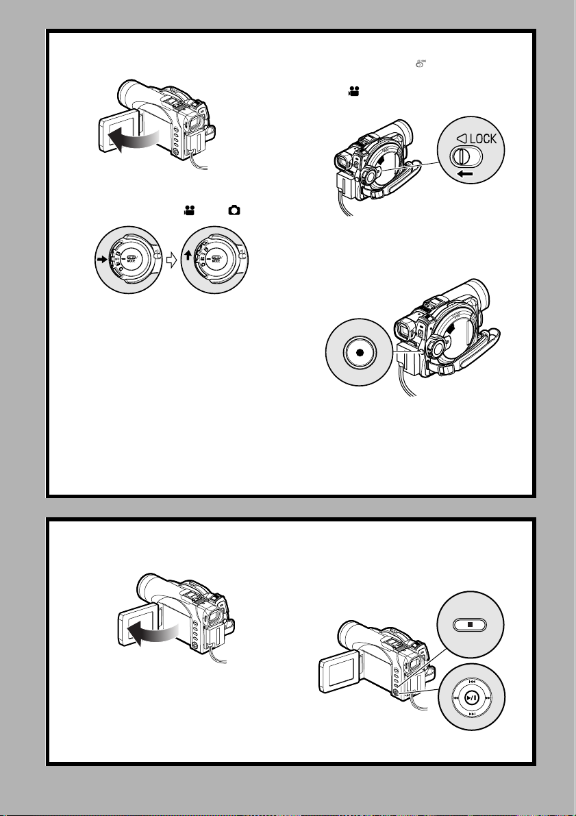
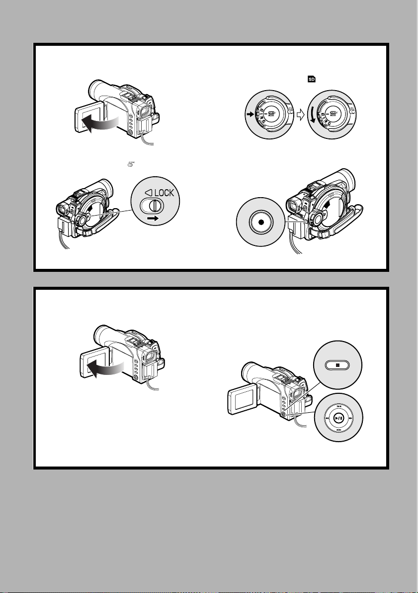
3 Start recording (P. 51).
1. Open the LCD monitor (See page 38).
2. While holding the switch at the center of power
switch, set the switch to “ ” or “ ”.
Note
:
When using an unformatted disc, format (initialize) it on this DVD Video Camera.
If unformatted disc is inserted into this DVD Video Camera, a message will appear: Format the disc following the
instructions on screen (P. 47, 125). Initializing the disc will erase all the recorded contents: make sure the contents
on disc are not valuable before initializing the disc.
3. Set the LOCK switch to (to the left) to prevent
accidental switching of recording mode.*
* Only in mode.
4. Press the REC button.
Recording will start.
Pressing the REC button again will stop recording.
REC button
4 View the playback of recorded content on LCD monitor.
1. Open the LCD monitor (See page 38). 2. After recording is finished, press the A button.
The recorded scene will be played back.
3. Press the g button to stop playback.
25
Page 26
Try to Record and Play Back Using Card (Photo)
Only photos can be recorded on card.
1 Connect power supply (P. 45).
Power c able
3
DC cord
Connect them in sequence of the digits.
2 Insert a card (P. 49).
1. Open the cover of card insertion slot with power
turned off.
2. Put in a card.
AC adaptor
3. Insert the card all the way until it locks.
26
Page 27
3 Start recording (P. 52).
1. Open the LCD monitor (See page 38).
2. Set the LOCK switch to (to the right).
3. While holding the switch at the center of power
switch, set the switch to “ ”.
4. Press the REC button.
Pressing REC once will record one photo.
REC button
4 View the playback of recorded content on LCD monitor.
1. Open the LCD monitor (P. 38). 2.Press the A button in recording pause status: the
recorded scene will be played back.
3. Press the g button to stop playback.
27
Page 28
Discs and Cards
The following table lists the storage media (discs and cards) that can be used on this DVD Video Camera
and the functions which are available with them:
Media
Function DVD-RAM disc DVD-R disc
Recording movie ll
Recording still l
Deleting recorded image l
Editing on this DVD
Video Camera
Playback on DVD player
Playback on DVD video
recorder
l
l
*1
-
*3
-
-
--
*2
l
*2
l
SD Memory Card/
MultiMediaCard
-
l
l
-
*4
-
l: Functions available;
*1:
Can be played back on DVD players with the
*2:
Must be finalized (see “Terminology”, P. 148) on this DVD Video Camera before DVD-R disc can be played back on
DVD player or DVD-RAM recorder (See page 127). May not be playable on some DVD players.
*3:
Compatible with DVD video recorders that conform to 8 cm DVD-RAM.
*4:
Some DVD video recorders incorporate a device that can play back SD memory card and multimedia card.
mark.
-
: Not available
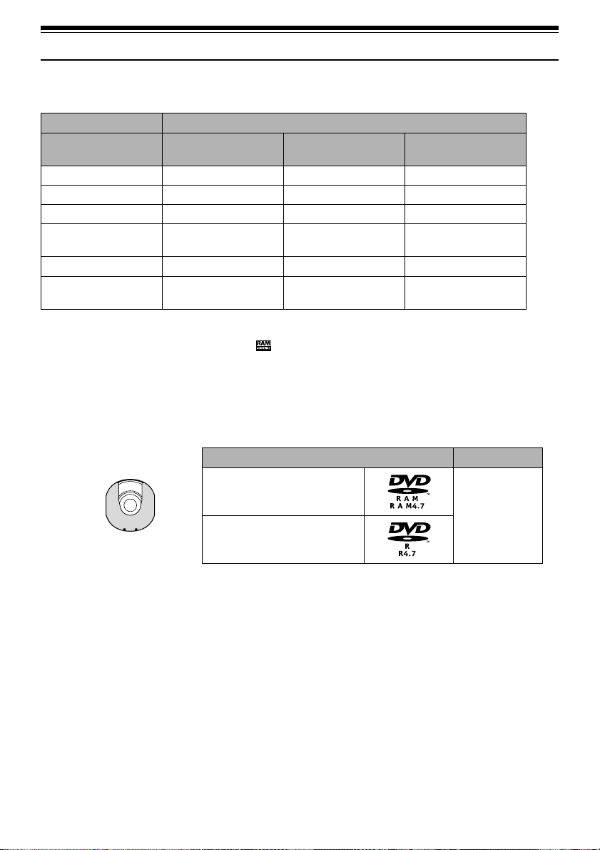
Available Discs
Usable discs and logos Shape
DVD-RAM Ver. 2.1 (8 cm)
In Round DVD
DVD-R
[for General Ver. 2.0 (8 cm)]
This DVD Video Camera uses 8 cm DVD-RAM discs
and 8 cm DVD-R discs for camcorder use.
Discs removed from Round DVD Holder cannot be used
on this DVD Video Camera: Use them only in the holder.
Do not insert a bare disc removed from the holder into the
DVD Video Camera: It will not be removable.
Note:
• It is recommended that you use Panasonic discs, since
their compatibility with this DVD Video Camera has been
confirmed. Using a disc other than those made by
Panasonic may not allow the DVD Video Camera to
deliver optimum performance.
• It is necessary to initialize an unformatted DVD-RAM
disc. When an unformatted disc is inserted into the DVD
Video Camera, a message will appear: Initialize the disc
following the instructions on screen (P. 125).
• The Round DVD Holder cannot be used on DVD Video
Cameras that use square type adapters.
• Image data edited on PC and certain types of image data
may not be visible on this DVD Video Camera.
• The image data recorded on another device may not be
playable on this DVD Video Camera.
Holder
28
Page 29

Information on DVD-R Disc
You cannot record a still on DVD-R disc, or delete any
recorded images or data.
For optimum recording on DVD-R disc, this DVD Video
Camera writes control data to the disc in order to
automatically make adjustments when it is inserted and
ejected accompanying recording. If the disc has no area
to be written for adjustment, recording may not be
possible. To prevent this, do not insert or eject a DVD-R
disc which has been recorded on more than 50 times. The
DVD Video Camera will not perform “write adjustment”
when the DVD Video Camera is turned on again, from
off, for recording with the disc in it, or when no recording
is made, even if the disc is removed and then reinserted.
lFinalizing DVD-R disc
Before using the 8 cm DVD-R disc on a DVD player or
DVD video recorder that is compatible with 8 cm DVDR disc, the disc must be finalized on this DVD Video
Camera. For the finalizing procedure of 8 cm DVD-R
disc, refer to “Finalizing DVD-R Disc (Finalize Disc)”
(P. 127).
Note:
• When using an unformatted DVD-R disc, it is necessary
to format it on this DVD Video Camera (See page 47).
• Do not insert a DVD-R disc recorded on this DVD Video
Camera but not finalized, into a recordable device, such
as a DVD video recorder: The recorded data may be
damaged.
• DVD-R discs edited and finalized on PC or those finalized
on another DVD video recorder may not be playable on
this DVD Video Camera, depending on the editing
software used or recording status of DVD-R disc.
• Refer to the remaining time indicated on the LCD of DVD
Video Camera to check the capacity of DVD-R disc.
Examples of Discs that Cannot be Used on this DVD Video Camera
• DVD-RAM (2.6 GB) Ver. 1.0 • DVD-ROM • MO
• DVD-R (3.9 GB) Ver. 1.0 • DVD-Video • MD
• DVD-R (4.7 GB) for Authoring Ver. 2.0 • CD-R • iD
• DVD-RW • CD-RW • Floppy disk
• DVD+RW • CD • Discs other than those with diameter of 8 cm
• DVD+R • LD • CD-ROM
Note:
Discs recorded on PC or DVD video recorder may not be playable on this DVD Video Camera: If so, message “This disc
cannot be used. ” will appear. Also, blue thumbnails will appear (Fig. 1* on page 30), or nor mal playback will not be possible.
29
Page 30
Handling Discs
lUsing discs
DVD-RAM and DVD-R discs are very delicate
recording media. Carefully read the following cautions
and observe them:
• When using a disc in this DVD Video Camera, be sure
to keep it in Round DVD Holder.
• Always use a brand new disc when recording
important material.
• Be sure not to touch the exposed
disc portion, and be careful that
no dirt adheres to it.
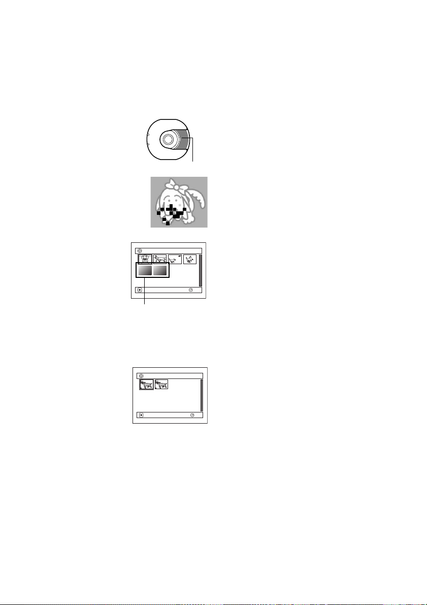
• If there is dust, scratch, dirt on
disc or if it is warped, the
following phenomena may occur:
− Block noise in playback image
− Momentary stop of playback
image
− Sound interrupted during
playback, or abnormal sound
− Blue thumbnail display*
(Fig. 1)
− Disc cannot correctly be
recognized
− Delay between video and
audio
Even if disc is normal, the
above phenomena may
occasionally occur. While the ACCESS/PC indicator
is lit, do not subject disc to vibrations or impact, and
avoid using DVD Video Camera at extremely high or
low temperatures, or in an environment where
condensation is likely to occur.
• When recording images, the
DVD Video Camera may
avoid the portions of disc
where recording is not
possible, due to dust,
scratches, etc. [It will pause
m at such a portion and
automatically restart
recording (n).]
This will cause recording to
be interrupted for several seconds to several minutes,
and multiple thumbnails will be created by one
recording session as shown above. In this case, the
recordable time on disc will decrease.
• Be careful when removing the disc since the metal of
removal slot of DVD Video Camera, and disc itself,
may be hot.
Do not touch
Block noise
001/ 006All Programs
PLAY
(Fig. 1)
*
PLAY
(Recording one scene
may produce multiple
thumbnails.)
RAM
001 / 002All Programs
RAM
lStoring discs
• When storing disc, insert it in Round DVD Holder into
plastic case.
• Be careful that no condensation occurs on disc.
• Do not place disc in the following places:
− Direct sunlight for a long time
− Where humidity is high or in dusty place
− While there is heat from a heater, etc.
Note:
• See page 74 when cleaning the removed disc.
• See page 73 for how to handle disc removed from Round
DVD Holder.
• See page 74 for how to set the disc removed from
Round DVD Holder or another disc correctly into Round
DVD Holder.
30
Page 31
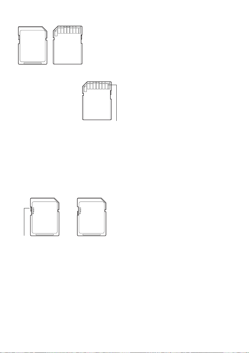
Available Cards
SD Memory
Card and
MultiMediaCard
can be used in
this DVD Video
Camera.
lHandling card
• Do not use cards other than the
designated ones.
• Do not touch the card terminal or
allow it to touch metal.
• Do not paste anything other than
exclusive label on label pasting
portion.
• Do not subject card to impact,
bend card or drop it.
• Do not disassemble card or modify it.
• Do not expose card to water.
• Do not use or store card in the following places:
− Where the temperature is high, such as in vehicle at
high temperatures, in direct sunlight or near a heater.
− Where humidity is high, or in dusty place
• Keep the Memory Card out of reach of Children to
prevent swallowing.
• When the write-protect switch on SD Memory Card is
locked, no recording, deletion or editing will be
possible on the card.
Te r mi n a l
lCommon cautions for disc and card
• It is recommended that you create a backup file for
valuable data on hard disk of PC.
• Do not do the following, or the data on card may be
damaged or lost:
− Do not remove the card or turn DVD Video Camera
off during reading or writing of data
− Do not use DVD Video Camera in a place subject to
static electricity or electrical noise
Note:
• The reading/writing speed of MultiMediaCard is slower
than SD Memory Card. When MultiMediaCard is used,
the performance of certain features may be slightly
slower than advertised.
• We recommend that you use a Panasonic brand SD
Memory Card.
• This DVD Video Camera can play back image data
recorded on other digital cameras conforming to the DCF
(Design rule for Camera File system) standard which was
established by the Japan Electronics and Information
Technology Industries Association (JEITA). The range of
image data playable on this DVD Video Camera is that
with pixels from 80 horizontal × 60 vertical to 4000
horizontal × 3000 vertical.
• DCF is an integrated image file format for digital cameras:
Image files can be used on all digital devices conforming
to DCF.
• Image data edited on PC and certain types of image data
may not be viewable on this DVD Video Camera.
• The image data recorded on another device may not be
playable on this DVD Video Camera.
Write-protect switch
Locked status
31
Page 32

Storage Capacity of Disc or Card
Recordable Time of Movie (Video)
The recordable time will vary depending on the recording quality: See page 86 for the setting of recording quality.
Movie recordable time on one disc (on single side) (when recording only movies)
Recording quality
XTRA Approx. 18 min
FINE Approx. 30 min
STD Approx. 60 min
*4
LPCM
*1:
Variable bit recording (recording of more than 18 minutes may be possible because the transfer rate varies automatically
between approx. 3-10 Mbps)
*2:
Transfer rate: Approx. 6 Mbps
*3:
Transfer rate: Approx. 3 Mbps
*4:
Linear PCM recording (see “Terminology”, P. 148) (If your DVD player does not conform to MPEG 1 Audio Layer 2,
record in LPCM mode)
Note:
DVD-RAM DVD-R
No recording possible Approx. 30 min
Disc used
*1
No recording possible
*2
Approx. 30 min
*3
Approx. 60 min
Image quality prioritized
*2
*3
Recording time prioritized
• Audio in XTRA, FINE or STD mode is recorded in the
MPEG 1 Audio Layer 2 format, which is the option
standard of DVD video standard.
• No movie can be recorded on SD Memory Card or
MultiMediaCard.
• When using DVD-R disc, you cannot switch the movie
quality while recording on the disc: The DVD Video
Camera will be automatically set to the movie quality first
used with the disc for recording.
32
Page 33

Recordable Stills (Photos) on Disc
lNumber of recordable stills on one
side of disc: Up to 999
If the disc still has free space after recording 999 stills on
it, movies can also be recorded on it.
Recordable Stills (Photos) on Card
The number of recordable stills will vary depending on
the recording quality: see page 87 for the setting of
recording quality.
For VDR-M50PP
Capacity
8 MB
16 MB
32 MB
64 MB
128MB
256 MB
512 MB
Approx. 45 Approx. 95 Approx. 190
Approx. 100 Approx. 200 Approx. 400
Approx. 220 Approx. 440 Approx. 880
Approx. 440 Approx. 880 Approx. 1,760
Approx. 880 Approx. 1,760 Approx. 3,520
Approx. 1,760 Approx. 3,520 Approx. 7,040
Approx. 3,520 Approx. 7,040 Approx. 14,080
For VDR-M70PP
Capacity
8 MB
16 MB
32 MB
64 MB
128MB
256 MB
512 MB
(The numbers of recordable stills above are only for
reference)
Approx. 8 Approx. 14 Approx. 20
Approx. 22 Approx. 35 Approx. 50
Approx. 50 Approx. 80 Approx. 110
Approx. 100 Approx. 160 Approx. 220
Approx. 200 Approx. 320 Approx. 440
Approx. 400 Approx. 640 Approx. 880
Approx. 800 Approx. 1,280 Approx. 1,760
Recording quality
FINE NORM ECO
Recording quality
FINE NORM ECO
:
Note
• Cards used on other devices can be used on this DVD
Video Camera.
• No movie or music data recorded on card can be
checked, viewed or heard on this DVD Video Camera. In
addition, no such data file can be displayed on this DVD
Video Camera.
• Use the remaining capacity function to check the
remaining free space on disc before use. See “Verifying
Remaining Free Space on Disc or Card (Capacity)” on
page 124.
• Some still data recorded on this DVD Video Camera may
not be playable on another device.
Size and Quality of Photos
The pixel size of JPEG stills that can be recorded on this
DVD Video Camera is as follows:
Model
VDR-M50PP 640 × 480 pixels 640 × 480 pixels
VDR-M70PP 1 ,280 × 960 pixels 640 × 480 pixels
Camera input External input
The following table shows the file size and quality of one
JPEG still recorded on card:
File size
Quality
FINE Approx.
NORM Approx.
ECO Approx.
VDR-
M50PP
128 KB
64 KB
32 KB
Although still images are recorded on DVD-RAM disc
only in the FINE mode, the quality mode can be changed
when recording stills on card.
* See page 165 for the number of recordable stills.
Setting
VDR-
M70PP
Approx.
512 KB
Approx.
384 KB
Approx.
256 KB
Application
When image
quality is
prioritized
Standard
When number of
stills is prioritized
(quality will be
slightly inferior)
Note:
No still can be recorded on DVD-R disc.
33
Page 34

Setups
This section explains preparations for recording - setting up the DVD Video Camera and battery pack.
Setting Up the DVD Video Camera
Holding DVD Video Camera
Using Grip Belt
Insert your right hand from the bottom of DVD Video
Camera up to the base of your thumb.
Put your hand in a position where you can easily operate
the REC button and the Zoom lever.
Adjust the length of grip belt so that the DVD Video
Camera is stable when you press the REC button with
your thumb.
1) Detach the belt.
2) Ajust the length of grip belt.
3) Attach the belt.
Note:
Do not adjust the grip belt while holding the DVD Video Camera: Doing this could cause the DVD Video Camera to fall
and be damaged.
To use as a Hand Strap
Using the Grip Belt as a hand strap makes it easier to carry the DVD Video Camera.
1 Detach the Grip Belt from the Video Camera.
1) Open the Lock cover.
Lock cover
Open the lock cover while pinching the protection
portion of both ends.
2 Make it a hand strap.
1) Turn over the belt.
2) Pull the tip in the derection of the
arrow.
3) Attach the belt.
34
2) Push the Lock button and pull the grip belt from
the DVD Video Camera.
Support the DVD Video Camera securely by the
hand to avoid falling.
Lock button
Lock cover
Return the lock cover to the closed position
after pulling out the grip belt.
Page 35

To use as a Grip Belt again
1 Attach the tip of the grip belt to the DVD Video
Camera (1).
Press down the lock cover in the direction of the arrow
so that the belt will not fall out (2).
Attaching Shoulder Belt
Be sure to pass through the 2 slots.
Attaching Lens Cap
Pass the provided string through the hole in the Grip Belt Attachment part and pass it through the hole in the lens cap.
Lock cover
Pass the Shoulder belt through
the Shoulder belt attachments.
1 Attach the lens cap string to lens cap.
Shorter side is for the lens cap.
2 Attach the string to the attachment hole of DVD
Video Camera.
Detaching the grip belt makes things easier.
Note:
• Always keep the lens cap on when not using the DVD
Video Camera, to protect the lens.
• When recording, attach the lens cap to the grip belt by
hooking the tab inside the cap onto strap for comfortable
shooting.
When using as a hand strap, you cannot attach the lens
cap to it.
3 Push both sides of cap inward and attach it over the
lens.
Push and fit
35
Page 36

Inserting Battery into Remote Controller
Insert the provided button type battery into remote controller.
1 Slide the cover to remove it.
2 Insert the button type battery with the positive R
terminal facing up.
Battery stopper
3 Slide the cover to close it.
Note:
The life of the button type battery is approximately one year.
If the battery is discharged, no operation is possible with
remote controller: Replace the battery.
Removing Battery from Remote Controller
1 While pushing the battery stopper, slide the battery
out.
While pushing
battery stopper
Battery stopper
Warn ing:
• KEEP THE BATTERY AWAY FROM CHILDREN AND
PETS.
• IF SWALLOWED CONSULT A PHYSICIAN
IMMEDIATELY FOR EMERGENCY TREATMENT.
• BATTERY MAY EXPLODE IF NOT HANDLED
PROPERLY. DO NOT RECHARGE, DISASSEMBLE OR
DISPOSE OF IN FIRE.
Note
• Dispose of battery safely in accordance with local laws.
• Do not short circuit the battery.
• Do not hold the battery with metallic tweezers.
• Keep the battery in a dark, cool, dry place.
:
Do not dispose of in fire.
Warn ing:
Danger of explosion if battery is incorrectly replaced.
Replace only with the same or equivalent type
recommended by the equipment manufacturer.
Discard used batteries according to manufacturer’s
instructions. Risk of fire, explosion and burns. Do not
recharge, disassemble, heat above 212°F (100°C) or
inclnerate, Keep the Button-Type battery out of the
reach of children. Never put Button-Type battery in
mouth. If swallowed, call your doctor.
36
Page 37

lUsing Remote Controller
To operate the DVD Video Camera with the remote
controller, point it at the infrared receiver before pressing
buttons. If it does not work properly, do not forget to point
it at the receiver to repeat the action. The remote
controllable distance is up to 16 feet (5 m).
10
15
10
15
5
(
t
e
e
f
6
1
.
ox
r
p
p
A
Infrared
receiver
)
m
Viewing Subject Through Viewfinder
1 Pull out the viewfinder.
2 Turn the diopter control knob to adjust the focus to
suit your eyesight.
Diopter control
Note:
• When using the remote controller, make sure that the
infrared receiver on DVD Video Camera is not exposed to
direct sunlight or any intense light. If the infrared receiver
is subject to light stronger than the infrared light from
remote controller, the DVD Video Camera cannot be
operated by remote controller.
• If there is an obstacle between the remote control and
infrared receiver on DVD Video Camera, remote control
may not be possible.
• Depending on the type of fluorescent lamp in the room,
the remote controller may not work properly.
Caution:
Do not lift the DVD Video Camera by holding the
viewfinder or LCD monitor: If the viewfinder or LCD
monitor comes off, the DVD Video Camera will fall.
Pull out the
viewfinder.
8:00AM
SEP
30
2004
Note:
• If no image appears in viewfinder, refer to “Check 6” on
page 151.
• If the LCD monitor is open approximately 90°, the
viewfinder will be off.
• Focusing will not be correct unless the viewfinder is
pulled out.
37
Page 38

Viewing Image on LCD Monitor Screen
If you open the LCD monitor, you can monitor subject image on the LCD screen.
1 Open the LCD monitor.
The LCD monitor has a spot where you can hook your
finger. Hook the finger there to open the monitor.
90°
Hook your finger
lRange of LCD monitor movement
The LCD monitor can be opened up to approximately
90º.
If the LCD monitor is open 90°, the screen can be tilted
down by as much as 90°, and can also be tilted up and
turned up to 180° so the screen faces in the same direction
as the lens.
If the LCD monitor is turned 180° so the screen faces in
the same direction as the lens during recording, subject
image will also appear in the viewfinder as a mirror
image (left/right reversed).
Tilt the LCD monitor to adjust its vertical angle so that
you can easily see the screen .
Note:
• If no image appears on LCD monitor screen, refer to
“Check 7” on page 151.
• Be sure to open the LCD monitor approximately 90º
before changing its vertical angle.
• Do not record for a prolonged time with the LCD monitor
turned approximately 180
Video Camera body: Doing this could cause the DVD
Video Camera and LCD monitor to become hot.
º in close contact with the DVD
(Bottom)
90
180
38
Page 39

Closing LCD Monitor
Before closing the LCD monitor, be sure to reset it at a
right angle to the DVD Video Camera.
Close the LCD monitor, with the LCD screen facing
inward, until a click is heard.
Note:
• Be sure to return the LCD monitor to a right angles to the
DVD Video Camera before closing it. If the LCD monitor
is tilted or faces outward from the camera body, it cannot
be closed to the DVD Video Camera.
• If the LCD monitor is not securely locked to the DVD Video
Camera, no image will appear in the viewfinder.
:
Caution
Do not lift the DVD Video Camera by holding the
viewfinder or LCD monitor: If the viewfinder or LCD
monitor comes off, the DVD Video Camera will fall.
39
Page 40

Setting Date and Time
Set the current date and time so that the date and time at which you make a recording can be recorded
correctly.
The following procedure can also be used to correct the date and time you have already set.
MENU
Tilt up/down and left/right
to select, and then press
A to designate.
1 Turn the DVD Video Camera on.
2 Press the MENU button.
The menu screen will
appear.
3 Use the joystick to choose
“Date Setup” and then “Date
Set”.
4 Tilt the joystick to the right.
The figure for the month will
be selected.
[The digit that is highlighted
first depends on the date
display format (set up in
Date Mode): The digit on the left end of the date
display will be highlighted first.]
Note:
After setting the figure for the month, tilt the joystick to
the right to select the digit to be set. If you press the
A button after selecting the figure for the month, the
screen for verifying the set date will appear instead of
the screen for setting day, year or time.
Camera Funct i ons Setup
Progra
m
AE : Au t o
W
hi te Bal. : Auto
EIS :On
Dig. Z
oom
: 40x
Wind Cut:O
Wide
:
ENTER RETURN
Da t e Se t u p
ENTER RETURN
Da t e Se t u p
ENTER RETURN
4:3
Da t e Mode
Da t e Se t JAN 1 2004
Da t e Mode
Da t e Se t JAN
ff
12: 00AM
1 2004
12: 00AM
5 Tilt the joystick to the left or
the right to select the digit
Da t e Se t u p
you want to set in sequence.
Tilt the joystick up or down
to select the number for
RAM
current date/time, and then
repeat step 5 to set the current date and time.
Note:
To stop date/time setting midway, press the C button.
6 After setting the current date
and time, press the A
RAM
button.
The screen for verifying the
set date will appear.
ENTER RETURN
Da t e Se t
ENTER
7 If the displayed date and time are correct, use the
joystick to choose “YES”, and then press the
RAM
A button.
The date and time will be set, and the DVD Video
Camera will enter recording pause mode.
Choosing “NO” will restore the menu screen.
Important Note:
This DVD Video Camera incorporates a rechargeable
battery to store the date and time in memory. If this
built-in battery is exhausted, the date and time will be
reset. To prevent this, connect the AC adaptor to DVD
Video Camera every 3 months, and leave it to charge
for at least 24 hours with the DVD Video Camera turned
off: The built-in battery will be charged.
Da t e Mode
Da t e Se t SEP 30 2004
SEP
30
Da te set up?
YES NO
2004 8: 00A
8: 00AM
M
RAM
RAM
40
Page 41

Changing Display Format of Date and Time
You can select one of three date display formats: month/day/year, day/month/year, or year/month/day. The time
display format will also change as follows:
Display format Example of display
M/D/Y
D/M/Y
Y/M/D
5:00PM
SEP 30 2004
17:00
30. 9.2004
17:00
2004. 9.30
1 Press the MENU button.
The menu screen will appear.
2 Use the joystick to choose
“Date Mode” on the “Date
Setup” menu screen, and
then press the A button.
The options will appear to
the right of “Date Mode”: The Zmark will be attached
to the currently selected option.
Da t e Se t u p
Da t e Mode
Da t e Se t
ENTER RETURN
M/D/ Y
D/M/ Y
Y/M/D
3 Use the joystick to select the
desired date display format,
Da t e Se t u p
and then press the
A button.
ENTER RETURN
The menu screen for setting date will be restored, and
RAM
the “Date Mode” will have been changed as you
designated.
4 Press the MENU button to switch off the menu
screen.
Note:
If the date display format has been changed, the display
format during playback as well as during recording will also
be changed (See page 54).
Da t e Mode
Da t e Se t
D/M/ Y
RAM
41
Page 42

About the Battery Pack
Attaching Battery Pack to DVD Video Camera
1 Fit the battery pack to the battery attachment platform
on this DVD Video Camera and slide it upward until
a click is heard.
Terminal
must
face up.
Note:
• Make sure that the battery pack is in the correct
orientation.
• Make sure that the battery pack is securely attached:
Incomplete attachment could cause the battery pack to
fall, resulting in damage.
Removing Battery Pack
After using the DVD Video Camera, remove the battery pack from it.
1 Slide the BATTERY EJECT switch on the bottom of
DVD Video Camera: The battery pack can be
removed.
2 Slide the battery pack downward to remove it.
Note:
• For safety, be sure to turn the DVD Video Camera off
before attaching or removing the battery pack.
• Be careful not to drop the removed battery pack.
• If the battery remains attached, minute level current will
flow even if the DVD Video Camera is off, and the battery
pack will discharge.
42
2
1
Page 43

lRecordable time with fully charged
battery pack (with no zoom
operation, etc.)
For your reference, the approximate DVD Video Camera
recordable time with fully charged battery pack [with
model CGA-DU14A]:
VDR-M50PP
Video
quality
mode
*1
*2
When using
viewfinder
When using
LCD monitor
viewfinder
When using
LCD monitor
viewfinder
When using
LCD monitor
When using
viewfinder
When using
LCD monitor
XTRA
FINE When using
STD When using
LPCM
VDR-M70PP
Video
quality
mode
*1
*2
When using
viewfinder
When using
LCD monitor
viewfinder
When using
LCD monitor
viewfinder
When using
LCD monitor
When using
viewfinder
When using
LCD monitor
XTRA
FINE When using
STD When using
LPCM
DVD-RAM disc DVD-R disc
approx. 140 min
approx. 120 min
approx. 140 min approx. 135 min
approx. 120 min approx. 115 min
approx. 165 min approx. 160 min
approx. 135 min approx. 130 min
−
−
DVD-RAM disc DVD-R disc
approx. 130 min
approx. 110 min
approx. 130 min approx. 125 min
approx. 110 min approx. 105 min
approx. 150 min approx. 145 min
approx. 125 min approx. 120 min
−
−
−
−
approx. 135 min
approx. 115 min
−
−
approx. 125 min
approx. 105 min
Continuous Recording (without zoom):
The continuous recording time of DVD Video Camera in
the left table shows the available recording time when the
DVD Video Camera is in the recording mode without
using any other function after recording is started. In
actual recording, the battery pack will discharge 2-3
times faster than this reference since the REC button and
zoom are being operated, and playback is performed.
Assume that the recordable time with a fully charged
battery pack is between 40 and 60 minutes [with model
CGA-DU14A], and prepare the type and number of
batteries to allow for the time you are planning to record
on the DVD Video Camera.
Note that the battery pack discharges faster in cold
places.
lThe time taken for charging the
battery pack is as follows
[at 77ºF (25 ºC)]
CGA-DU14A
165 min
Note:
• See page 158 when charging is not possible.
• The charge time will vary depending on the remaining
battery level.
• During and after charging, the battery pack will be warm,
but this does not indicate a fault.
• If the following phenomena appear, the battery pack
may be dead: Replace it.
- Charging does not start within 10 seconds (the
CHARGE indicator does not light).
- The battery pack cannot be charged up to 75% if more
than 9 hours have elapsed after charging started.
- The battery pack cannot be fully charged if more than
5 hours have elapsed after it was charged to 75%.
• Charge the battery pack at ambient temperature 50°F to
86°F (10°C to 30°C): Charging at temperatures other
than this range could damage the battery pack.
*1
The time in XTRA mode is only for reference: It varies
depending on recording contents.
*2
LPCM mode can be set only when DVD-R disc is used.
43
Page 44

Remaining Battery Level Indicator
When the battery pack is used to power the DVD Video Camera, the battery remaining level appears in the viewfinder
or on the LCD screen as follows:
Fully charged Nearly empty
(Blinks)
Shows remaining level
Note:
• If you use the optional CGA-DU07A battery pack at low temperatures, “ ” may not appear, and the battery usable
time may be shorter.
• If you use the provided CGA-DU14A battery pack, the remaining level indicator “ ” may be displayed for an extended
period, and “ ” or “ ” may be displayed for a shorter period.
Efficient Use of Battery Pack
Charge battery pack immediately before using
DVD Video Camera:
The battery pack will slightly discharge even if it is
detached from the DVD Video Camera. If the battery
pack is left attached to DVD Video Camera, it will
consume a slight amount of power.
Important Note:
Therefore, it is recommended that you charge the
battery pack shortly before using the DVD Video
Camera, usually on the day before you plan to use it.
Since the battery pack used for this DVD Video Camera
is free from the memory effect, you do not need to
completely discharge the battery pack before charging it.
When not using the DVD Video Camera for an
extended period:
It is recommended that you fully charge the battery pack
once a year, attach it to DVD Video Camera and use it up;
then remove the battery pack and store it in a cool place
again.
Store in cool place:
When you are not using the DVD Video Camera, remove
the battery pack and store it in a cool place. If you store
it in a place where the temperature is high, the battery life
will be shortened. Be especially sure not to store the
battery pack in an environment (in a closed vehicle) over
140°F (60°C): Neglecting this could damage the battery
pack.
Battery life:
Battery life varies greatly depending on the ambient
environment and how often the DVD Video Camera is
used. If the usable time of DVD Video Camera with a
fully charged battery pack is noticeably short, the battery
pack is probably dead: Purchase a new one.
Power save and discharge of battery pack:
It is recommended that you turn the DVD Video Camera
off in status other than recording, since even during
recording pause battery power is consumed at the same
level as during recording.
If, when you specify Power Save On, the recording pause
status continues for approximately 5 minutes, the DVD
Video Camera will automatically turn off.
To set or release power save, see “Turning DVD Video
Camera Off Automatically (Power Save)” on page 92.
44
Page 45

Using DVD Video Camera with AC adaptor
It is recommended that you use the AC adaptor to power the DVD Video Camera from a household AC outlet when
you perform settings on it, play back or edit images, or use it indoors.
Note:
Be sure to use the specified AC adaptor to power the DVD Video Camera. Using other AC adaptors could cause electric
shock or result in fire.
Power cable
DC cord
1 Connect the power cable to AC adaptor.
2 Plug the power cable into household AC outlet.
3 Plug one end of DC cord into the DC output jack on
AC adaptor.
4 Attach the other end of DC cord to the battery
attachment platform on DVD Video Camera.
AC adaptor
Note:
The AC adaptor can be used around the world. An AC plug
adaptor is required in some foreign countries. If you need
one, purchase it from your distributor.
AC 200-240V
AC Plug Adaptor (not supplied)
45
Page 46

Inserting and Removing Disc
Inserting Disc
1 Press down the DISC EJECT lever once and release
it.
A few moments after the ACCESS/PC indicator
blinks, the cover of disc insertion compartment will
open slightly.
2 Gently open the cover by hand until it stops.
3 Insert the disc, in Round DVD Holder, into the disc
guide until it stops.
Note that the recording/playback surface of disc must
face the inside of DVD Video Camera. The
orientation for inserting the disc into the disc guide is
also specific: load the disc correctly, referring to the
figure below.
PUSH CLOSE
portion
Disc cover
DISC EJECT
lever
The disc exposed portion must face in the same
•
direction as the lens, as shown in figure.
• The recording/playback side must face the inside of
DVD Video Camera.
Disc guide
Correct
orientation
Incorrect orientation
4 Push the section marked “PUSH CLOSE” on the
cover of disc insertion compartment, to close the
cover.
5 Turn the DVD Video Camera on ( or ).
When “DISC ACCESS” disappears, the DVD Video
Camera is ready for recording.
lIdentifying recording/playback
sides of disc:
Single sided disc:
The recording/playback side is
opposite to the printed label.
Double-sided disc:
The recording/playback side of
“SIDE A” is opposite to the
“SIDE A” marked side.
The recording/playback side of
“SIDE B” is the “SIDE A”
marked side.
“SIDE A” mark
The opposite side is
the “SIDE A”
recording/playback
side.
46
Page 47

Note:
• Disc cannot be inserted or removed unless the battery
pack or AC adaptor is connected to DVD Video Camera.
• See page 74 for how to set disc in Round DVD Holder.
• If there is some delay before recording starts, refer to
“Check 4” on page 150.
• The disc insertion orientation is specific: Forcibly
inserting a disc in wrong orientation could damage the
DVD Video Camera or Round DVD Holder of disc.
• If the disc is not correctly inserted, the cover will not close.
Never try to forcibly close the cover: This could cause
damage. Reinsert the disc properly.
• If a single-sided disc is inserted into DVD Video Camera
with the printed label facing the inside, an error message
will appear. Remove the disc and reinsert it with its
recording/playback side facing the inside. See “Error
Messages” on page 152.
• When using double-sided disc
Recording is possible on both sides of double-sided disc.
However, when recording or playback on one side is
finished, recording or playback will not move
automatically to the other side. Remove the disc once
from the DVD Video Camera, turn over the disc in Round
DVD Holder and insert it again for continued use.
lWhen using brand-new DVD-R disc
Recognition of the disc will
start.
The messages on the right will
appear in sequence by pressing
the A button between
messages.
When recording on this
DVD Video Camera:
When the first message
“Format the disc now?”
appears, choose “YES” and
then press the A button. The
disc will be automatically
formatted.
When formatting is complete,
“DVD-R disc, Video mode
cannot be changed” will appear
(See page 155): Press the A
button to erase the message.
Once formatted, a DVD-R disc
can no longer be recorded on by
a PC, even if it has not been
recorded on by this DVD Video
Camera.
Note:
See page 86 for movie quality mode.
m
at Disc
For
This disc must be formatted
before it can be used by
this camera.
NEXT
CANCEL
Format Disc
Do not format this disc
if you want to record from
the PC connect ion terminal.
NEXT
CANCEL
For
m
at Disc
Format the disc now?
YES NO
ENTER
When recording data from PC:
While the above messages are being displayed, press the
g button, or when message “Format the disc now?”
appears, choose “NO” and then press the A button.
If data from PC has not yet been recorded, the disc can be
made usable on this DVD Video Camera. When inserting
the disc into this DVD Video Camera, the same message
will appear: If you wish to use it on this DVD Video
Camera, choose “YES”.
Note:
Do not initialize a disc on which you wish to record data
created using the application MyDVD on PC.
47
Page 48

Removing Disc
1 Set the power switch to “OFF”
to turn the DVD Video Camera
off.
2 Press down the DISC EJECT
lever once and release it.
In a moment, the cover of disc
insertion compartment will
open slightly.
3 Gently open the cover until it
stops.
When the cover is fully open,
the disc will slightly come out
from the disc guide, and stop.
DISC EJECT
Note:
• Even after the DVD Video Camera is turned on, the disc
can be removed unless it is in recording status. Hold
down the DISC EJECT lever for approximately 2
seconds, and then release it to remove the disc. (The
DISC EJECT indicator on the LCD screen will blink.) It is
recommended that you turn the DVD Video Camera off
before inserting or removing disc to prevent
misoperation.
• Do not remove the battery pack or disconnect the AC
adaptor during removal of the disc or until power is
completely turned off: If you do, the disc cover will not
open. If this happens, reattach the battery pack or AC
adaptor, push down the DISC EJECT lever once, and
then release it.
• Do not insert anything other than the 8 cm DVD-RAM or
DVD-R disc into the disc insertion block: Doing so could
cause malfunctions.
• Set the power switch to “OFF” to turn the DVD Video
Camera off.
• When inserting or removing the disc, be careful not to
touch the inside of DVD Video Camera [especially, the
lens of laser pickup (see “Terminology” on page 148 )].
• When inserting or removing the disc, connect a charged
battery pack or AC adaptor to the DVD Video Camera:
The disc cover will not open unless the DVD Video
Camera is powered.
4 Remove the disc.
Hold the top of Round
DVD Holder as shown in
the illustration and
gently pull it out.
Note:
Be careful not to touch the
exposed disc portion
when removing the disc.
5 Gently push the section
indicated “PUSH CLOSE”
on the cover of disc insertion
compartment (on side) to
close the cover.
48
When grasping the holder,
avoid the exposed disc
portion.
Page 49

Inserting and Removing Card
1
Turn the DVD Video Camera off.
2 Open the cover of card
insertion slot.
3 Insert card with its contacts
inward until it locks.
Label pasting
portion
Removing Card
Push the center of card edge:
The card will come out so that
it can be held by fingers.
Note:
Do not push the label pasting
portion of SD Memory Card when
removing it: Doing so could
damage the SD Memory Card.
When you close the cover, be sure
not to insert the grip belt into the
insertion slot. If you insert the grip
belt into the insertion slot, the
insertion slot will be damaged.
4 Close the cover of card
insertion slot.
49
Page 50

Basic Techniques
This section explains the basic techniques of recording movies and still images, and also basic settings
on DVD Video Camera.
Basic Operation of DVD Video Camera
Turning DVD Video Camera On or Off
While holding down the button at the center of power
switch, set the switch according to each recording
function:
Set to “ ”:
To record still on SD Memory
Card or MultiMediaCard
Set to “OFF”:
The DVD Video Camera will
turn off.
Set to “ ”:
To record movie on DVDRAM or DVD-R disc
Set to “ ”:
To record still on DVD-RAM
disc.
Note:
• Once you turn the DVD Video Camera on to let it
recognize the disc, you can immediately record or play
back the same disc when the DVD Video Camera is
turned on again (DVD-RAM). However, if you remove the
disc, replace it, or if the date changes after power is
turned on, it will take some time for the DVD Video
Camera to start because it must recognize the disc again
(See page 150).
• Once you have turned the DVD Video Camera on to
record, you can immediately start recording when turning
the DVD Video Camera on next time (DVD-R disc).
• It will take some time for the DVD Video Camera to display
the Disc navigation screen after power is turned on.
• When you turn the DVD Video Camera on, the ACCESS
indicator will light or blink to show that the DVD Video
Camera is recognizing the disc or card: During this time,
no operation, such as recording, can be performed.
After several seconds, the ACCESS indicator will go out,
and operating the DVD Video Camera will be possible.
If the ACCESS indicator does not go out, refer to “Check
4” on page 150.
Power ON status
During playback, set the power switch to “ ” or
“ ” when using disc, or set it to “ ” when using
card.
Turn the switch while holding down the button at the
center of switch.
Power switch
50
CARD ACCESS
indicator
ACCESS/PC
indicator
• When the DVD Video Camera is turned on, the self-
diagnosis function operates and a message may appear.
In this case, refer to “Error Messages” on page 152 and
take corrective action.
• While the ACCESS/PC or CARD ACCESS indicator is lit
or blinking, do not cause impact or vibration to the DVD
Video Camera.
Page 51

12
Recording Movie
Before You Begin
REC button
Pressing REC once will
start recording;
pressing it once again
will temporarily stop
recording.
Turn the DVD Video Camera on.
1
Set the power switch to “ ” to turn the DVD Video
Camera on.
After the ACCESS/PC indicator goes out, perform
the subsequent operations:
• Insert a recordable DVD-RAM or DVD-R disc into this DVD Video Camera.
ACCESS/PC indicator
Power switch
2 Check the subject on the screen (viewfinder or LCD).
If using the viewfinder, pull it out.
3 Press the REC button.
The “m” mark in the viewfinder or on the LCD
screen will change to the “n” mark, and
recording will start.
During recording, the recording indicator on the front
of the DVD Video Camera will light.
Pressing REC again during recording will set the
DVD Video Camera to recording pause mode.
further recording can be made while “DISC ACCESS” is
being displayed.
Recording will restart after the message disappears.
• Do not turn power off while message “DISC ACCESS” is
being displayed.
• Take care that power is not interrupted while the
ACCESS/PC indicator is blinking.
• The minimum recordable time of movie is approximately
3 seconds.
• See page 93 for setting of Record LED (recording
indicator) On/Off.
• For various functions available during recording, see
“Setting Up Camera Functions” on page 80.
• Panasonic cannot be responsible for video and audio that
cannot be recorded or edited because of any defect.
• The power switch can be changed even during recording,
but the operation will not be changed.
• Each time the DVD Video Camera enters the recording
pause mode, the counter display will be reset to
“0:00:00”.
• When using DVD-R disc, do not perform the following, or
data on the disc may not be read:
- Using another device, doing additional recording on
DVD-R disc first recorded on this DVD Video Camera
- Using this DVD Video Camera, doing additional
recording on DVD-R disc recorded on another device
• It is recommended that you set the LOCK switch to (to
the left) to prevent the power switch in the “ ” position
from accidentally moving to “ ”.
4 When recording is finished, turn the DVD Video
Camera off.
Note:
• See “Check 1” on page 150 when recording movie is not
possible.
• See “Check 4” on page 150 if it takes some time before
recording is possible.
• See “Check 5” on page 151 if the DVD Video Camera
does not operate.
• See page 54 for on-screen information display.
• It is recommended that you use DVD-RAM disc from
which recorded contents can be deleted.
• Sound is recorded from the internal stereo microphone
on the front of DVD Video Camera: Take care that this
microphone is not blocked.
• You can press the REC button immediately after the DVD
Video Camera enters recording pause mode, but no
51
Page 52

Recording Stills
13
Note:
Recording of still images is possible on DVD-RAM disc and
card.
ACCESS/PC
indicator
REC button
Power switch
CARD
ACCESS
indicator
1 Turn the DVD Video Camera on.
When using DVD-RAM disc:
Set the power switch to “ ”.
When using card:
Set the power switch to “ ”.
After the ACCESS indicator goes out, perform the
subsequent operations:
2 Check the subject on the screen (viewfinder or LCD).
3 Press the REC button.
The DVD Video Camera automatically focuses on
the subject at the center of screen (when auto focus is
selected).
The screen will be black, and then the recorded still
will be displayed. When the “m” mark appears, you
can proceed with the next recording; while “DISC
ACCESS” or “CARD ACCESS” is being displayed,
you cannot proceed with the next recording.
4 Set the power switch to “OFF” to turn the DVD Video
Camera off.
Turn power off only after message “DISC ACCESS”
disappears.
Note:
• See “Size and Quality of Photos” on page 33 for details
about photos on card.
• See “Check 2” on page 150 if recording photos is not
possible.
• Do not operate the power switch or remove the card while
the ACCESS/PC or CARD ACCESS indicator is lit or
blinking: Doing so may damage the card or the data on
card.
• With VDR-M70PP, the range of screen in which
recording is possible will be different for movie and still.
• The DVD Video Camera automatically sets the shutter
speed between 1/800 and 1/30 second (between 1/800
and 1/10 second if Program AE has been set to Low
Light) depending on subject brightness.
52
Page 53

123
Compensating for Backlight
When subject is lit from behind , this function will compensate for lighting so that the subject is not too dark.
1
Press the BACK LIGHT button during recording.
REC
0:00:09
REM
Backlight correction icon
30MIN
FINE
SEP
8:00AM
30
2004
The backlight correction icon will appear.
Note:
• Pressing the BACK LIGHT button will alternate backlight
setting between on and off.
• The backlight setting will automatically return to “off”
when the DVD Video Camera is turned off.
53
Page 54

123
On-Screen Information
Various types of information will appear in the viewfinder or on the LCD screen during recording.
Information Display during Recording
o Manual focus
No display : Autofocus
o : (display in English or German): Manual
focus
: (display in French or Italian):
Manual focus
: (display in Spanish): Manual focus
3. Backlight compensation
No display : Backlight compensation OFF
m : Backlight compensation ON
4. Wind Cut (only in movie recording mode)
No display : Wind Cut OFF
Wide mode*
No display: Wide mode 4:3
:Wind Cut ON
2
: Wide mode 16:9
External flash
separately) is attached] (only in still recording mode)
A : Emits light automatically (AUTO)
*2
[when Video Flash (sold
: Always emits light
: No light emission
5. Self timer (only in still recording mode)
No display : Self timer OFF
q10 : Self timer ON (count is from 10 seconds)
6. External Input
LIN :AV input
SIN*2:S-VIDEO input
7. Recording status
n : During recording
m : During recording pause
No display
*3
LIN
0:00:00
REM
3 0 MIN
8:00AM
7
REC
123456
8
9
10
11
12
FINE
13
The above screen is an example for explanation: It is
different from the actual display.
10
FULL AUTO
DISC ACCESS
SEP 30 2004
1. Recording mode
:Movie
: Still with disc
: Still with card
*1: External input still with disc (field)
*1: External input still with disc (frame)
*1: External input still with card (field)
*1: External input still with card (frame)
2. e Program AE
No display : Auto
b :Sports
c :Portrait
d : Spotlight
e : Surf & Snow
f :Low Light
j White balance
No display : Auto
h :Set
i : Outdoor
j : Indoor
n Electronic image stabilizer (EIS)
No display : EIS OFF
n :EIS ON
14
15
16
17
18
54
Page 55

8. Zoom
W
X
(Digital Zoom: Off)
Y
(Digital Zoom: 40×)
[Digital Zoom: 500× (VDR-M50PP),
240× (VDR-M70PP), only in movie
recording mode]
9. Exposure correction
10. FULL AUTO indicator
11. Warn in g me ssa ge
12. Disc/Card type
I : DVD-RAM
K : DVD-R
J : DVD-RAM (write-protected)
M : DVD-R disc already finalized on this
N : DVD-R disc finalized on a device other
DVD Video Camera
O : SD Memory Card or MultiMediaCard
than this DVD Video Camera
P : Locked SD Memory Card
No display
*4
13. Movie recording quality (only when using disc)
XTRA : Image quality prioritized (only when
LPCM : Highest audio quality (only when using
FINE : Standard
STD : Recording time prioritized
Still recording quality (only when using card)
FINE : High quality
NORM : Standard
ECO : Number of recordable stills is prioritized
using DVD-RAM disc)
DVD-R disc)
14. Movie recording time (only in movie recording
mode)
15. Remaining space on disc/card
REM XX MIN*6: Remaining recordable minutes
*7
REM XX
during movie recording
: Number of remaining recordable
still images during still recording
*5
16. Remaining battery level
w(full charge)
x
y
z
(low remaining charge)
17. Brightness/Color density of LCD screen or Volume
:
The volume can be adjusted during external input
and playback.
18. Current date/time
*1 Appears only with external input when the DVD Video Camera is in PHOTO recording mode.
*2 Not displayed on VDR-M50PP.
*3 When no disc or card is in the DVD Video Camera, or disc has not yet been initialized, a write-protected disc or
locked card, or a disc or card with no remaining space, has been inserted.
*4 When a disc or card that cannot be used in this DVD Video Camera is inserted
*5 No remaining time or number will be displayed with a protected disc or locked card, or finalized DVD-R disc.
*6 In XTRA mode, possible recording time may be longer than the displayed time.
*7 The displayed number of recordable stills is for reference: The decreasing number may not be correct, depending
on recording conditions (not displayed with a DVD-R disc).
55
Page 56

lSwitching the information display mode
You can switch the display mode of on-screen information:
Press the DISPLAY button.
The full and minimum display modes will alternate.
• Full display mode: All types of information will appear.
• Minimum display mode: The recording mode (see 1 on page 54) and
recording status (see 7 on page 54) will appear. If the DVD Video
Camera has warning information, a warning message will appear.
Note:
The DVD Video Camera does not record the date and time as a part of the image. However, this information during
recording will be recorded with image as data which can be checked on Disc Navigation screen during playback (See
“Information Display during Playback” on page 63).
lDisplay when recording an image of yourself
When recording with the LCD screen facing the same direction as the lens, the
operating status will appear, and in addition, the battery remaining level will blink
when the battery pack has almost no remaining charge.
The following operating status indicator will light or blink to give a warning message
to user. The message can be checked by returning the LCD monitor 180° to the
original position from the position in which the LCD screen was facing the same
direction as the lens.
* :The disc has almost no free space.
Q :Write-protected disc or locked card is loaded.
N :You are attempting to record a still on DVD-R disc.
No display :Disc or card that cannot be used has been loaded.
l :The disc or card is full, or you are attempting to
Operating status/
warning message
Battery remaining
level
record a copy-guarded image.
Note:
• If the LCD screen is set facing the same direction as the lens, the LCD screen will display a mirror image (left and right
reversed).
• If the LCD screen is set facing the same direction as the lens, you can also view subject image in the viewfinder.
• Although you can switch to the manual focus, exposure and on-screen display modes even during recording with LCD
screen facing the same direction as lens, they will not appear on the screen.
56
Page 57

123
Zooming
This DVD Video Camera allows you to record using optical 18- (on VDR-M50PP) or 10- (on VDR-M70PP)
power zoom and digital zoom.
If you continue to hold the zoom lever on the “T” control
side with Dig. Zoom 40x or 240x specified, the digital
zoom will be activated midway (when optical 18-power
is exceeded on VDR-M50PP or optical 10-power is
exceeded on VDR-M70PP). You can set the digital zoom
up to 40x in photo mode, and 40x and 500x (on VDRM50PP) or 240x (on VDR-M70PP).
W:Recording wide area
(wide-angle)
1 Press the MENU button,
choose “Dig. Zoom” on the
“Camera Functions Setup”
menu screen, and then press
the A button.
Ca
m
era Funct i ons Setup
Program AE
W
hi te Bal.
EIS
Dig.Z
oom
Wind Cut
Wide
ENTER RETURN
2 Choose the desired
magnification, and then press the A button.
3 Press the MENU button to end setting.
Moving the zoom lever will display the digital zoom
bar.
*500x will appear on VDR-M50PP; 240x will appear
on VDR-M70PP.
0:00:00
REM
30MIN
T
8:00AM
SEP 3 0 2004
FINE
When Dig. Zoom is "Off"
W
When Dig. Zoom is "On"(40x)
When Dig. Zoom is "On"(240x)*
(only in movie recording)
W
T
TW
Digital zoom range
Digital zoom range
240x
40x
Of f
T: Recording enlarged
image (telephoto)
*
Note:
RAM
• Dig. Zoom setting will be stored in memory even if the
DVD Video Camera is turned off.
• You can also use the DIGITAL ZOOM button on remote
controller to switch the digital zoom setting: Pressing the
button during movie recording will switch the setting
between “Off”, “40×” and “500x” (on VDR-M50PP) or
“240x” (on VDR-M70PP): Pressing the button during still
recording will switch between “Off” and “40×”.
• If you set zoom to 500× (VDR-M50PP), 240× (VDR-
M70PP) when recording still, digital zoom will be up to
40×.
• When a subject is zoomed, it may be momentarily out of
focus.
• When digital zoom is engaged, the image quality will be
rougher.
• When using card, zooming only up to 40× is possible,
even when “500x” (on VDR-M50PP) or “240x” (on VDRM70PP) or “40×” has been chosen.
• If the power switch is set to “ ” with DVD-RAM disc
loaded, zooming only up to 40x is possible, even when
“500x” (on VDR-M50PP) or “240x” (on VDR-M70PP) has
been chosen.
• When you record pictures, with 10x or more of
magnification, the DVD Video Camera is susceptible to
shake. We recommend using a tripod (only for VDRM50PP).
57
Page 58

Macro Recording
Use the macro function when recording a small object from close-up position: You can shoot the subject as close as
approximately 13/16” (2 cm) from the lens surface, magnifying the image to fill the screen.
1 Aim the DVD Video Camera at the subject, and press
down the zoom lever to “W” control side.
Note:
• Zoom can be used, but the subject may not be focused,
depending on the distance to the subject. In this case,
move the zoom to “W” control side to focus.
• The amount of light tends to be insufficient during macro
recording: If the subject image is too dark, use additional
lighting.
Using Conversion Lens (Optional-User Provided)
Use tele-conversion lens or wide-conversion lens to record subjects for stronger telefoto or wide-angle effect. Use
conversion lenses with the following filter diameter.
VDR-M50PP/VDR-M70PP : 37 mm
Remove the lens hood on the top surface of lens, and then attach the conversion lens over the lens.
Conversion lensLens hood
(Remove)
Note:
• Be careful not to lose the removed lens hood.
• The four corners of screen may be dim depending on the
conversion lens used.
(Attach)
58
Page 59

Playing Back
123
Before You Begin
• Insert a disc or card recorded on this DVD Video Camera (P. 46, 49).
• Turn the DVD Video Camera on (P. 50).
Playing Back
1 Press A button in recording pause mode.
The DVD Video Camera will enter the playback
mode, and the scene you have recorded last will be
played back.
When playback is finished, the DVD Video Camera
will enter pause mode at the last image on disc.
If playback pause mode continues for as long as 5
minutes, the DVD Video Camera will automatically
return to recording pause mode.
2 Press the g button.
Note:
• During playback of movie, playback sound will be heard
from the speaker. Adjust the sound volume using the
volume control buttons ((, )).
• You can play back the audio recorded in Dolby AC 3 (2ch).
• To temporarily stop playback, press the A button.
Press the A button again to restart playback.
• Even if you stop playback midway and immediately start
recording again, the new image will be recorded after the
last scene on disc or card (the previous images will not be
overwritten).
• Image data edited on PC or certain types of image data
may not be displayed on this DVD Video Camera.
• Image data recorded on another camcorder may not be
playable on this DVD Video Camera.
• Depending on the amount of data to be played back, it
may take some time for the playback image to appear.
• Do not operate the power switch or remove the card while
the ACCESS/PC or CARD ACCESS indicator is lit or
blinking: Doing so may damage the card or the data on
card.
Playback will stop, and recording pause mode will be
restored.
59
Page 60

123
Playback from Start of Disc or Card
Use the Go To function (P. 62) or Disc Navigation
function (P. 95) to play back from the start of disc or card.
Search Playback of Movie
During playback, tilt the joystick right or left and hold it:
Search playback will start.
Hold to right : Scenes will be visually scanned
forward
Hold to left : Scenes will be visually scanned
backward
Release the joystick when you find the desired image:
Normal playback will start from that point.
Note:
• When you skip or search scenes from playback or
playback pause, the screen will be dark briefly.
• See “Check 3” on page 150 if search playback does not
operate normally.
Frame Advance/Frame Back/Slow Playback of Movie
During playback pause, tilt the joystick: Frame advance,
frame back or slow playback will start.
Tilt right once : Picture will advance
one frame.
Tilt left once : Picture will go back
one frame.
Hold right : Forward slow playback
Hold left : Reverse slow playback
After frame advance, frame back or slow playback, the
DVD Video Camera will enter playback pause mode.
Note:
• In forward slow, a rapidly moving subject image may be
distorted.
• The intervals for playing back frames in frame advance/
frame back/slow playback are as follows:
Frame advance and forward slow: Approx. 0.03 seconds
Frame back and reverse slow: Approx. 0.5 seconds
• No sound will be heard during search playback or slow
playback.
12
12
60
Page 61

Skip Playback of Movie
During playback, tilt the joystick up or down to locate the
start of desired scene.
Tilt down once : To skip to the first image of the
scene following the one being
played back, and start playback.
Tilt up once : To return to the first image of the
scene being played back, and start
playback.
Hold down : To continuously locate the
beginnings of scenes, starting
from the scene following the scene
being played back. When the
desired image appears, release the
joystick: Playback will start from
that point.
Hold up : To continuously locate the
beginnings of scenes backward,
starting from the scene preceding
the scene currently being played
back. When the desired image
appears, release the joystick:
Playback will start from that point.
Playing Back Stills
Tilt the joystick up or down during playback to quickly
play back stills in sequence.
Tilt down once : To display stills one by one
forward
Tilt up once : To display stills one by one
backward
12
Portion being played back
Tilt up twice Tilt up once Tilt down once Tilt down twice
Scene 1 Scene 2 Scene 3
Portion being played back
Tilt up once
Scene 1 Scene 2 Scene 3
Tilting up the joystick at a portion several seconds from
the start of scene being played back will return to the
start of the scene preceding that being played back.
Note:
Tilt down once
Tilt down twice
• If you perform skip playback during playback pause, the
DVD Video Camera will enter playback pause mode at
the beginning of the located scene.
• Tilting down in the last scene on disc will set the DVD
Video Camera to playback pause mode at the last image.
• See “Check 3” on page 150 if skip playback does not
operate normally.
13
[When using disc]
Releasing the joystick will start continuous playback.
[When using card]
When the joystick is released, the photo at that point will
be displayed, and then the DVD Video Camera will enter
playback pause mode.
Set the slide show function for continuous display (P.
129).
61
Page 62

123
Jumping to Specified Point (Go To)
1 Press the MENU button
during playback.
2 Choose the option (point you
want to go to), and then press
the A button.
Go T o
Top
End
Spec i f y
ENTER RETURN
RAM
lSpecifying the point to view
1 Choose “Specify” in step 2 above, and then press the
A button.
The screen for specifying the point to go to will
appear.
Position of currently
played back image
Go To
TOP ENDCURRENT
Cursor
0:00:00 0:24:240:03:26
TO P END
Cursor position
Total recording time of
all selected scenes
0:03:26
GO TO
ENTER
CANCEL
2 Use the joystick to select the desired time of chosen
point.
Tilt up : To select the start.
Tilt down : To select the end.
Tilt left or right :
–Press once: To move the cursor in 10-
–Hold down: To move the cursor in 1-
(When the start of scene is selected)
Cursor at current image position.
Cursor at (GO TO) position.
second units (1-still units for
card)
minute units (10-still units
for card)
Go To
TOP
0:00:00 0:24:240:03:26
GO TO
TO P END
0:00:00
ENTER
ENDCURRENT
CANCEL
Top : To go to the start, and enter playback pause.
End : To go to the end of last scene, and enter
playback pause.
Specify :To go to a specified point and enter
playback pause. See the following for
details.
3 Press the A button to enter the selection.
The DVD Video Camera will go to the specified point
and enter playback pause mode.
Pressing A again will start playback.
To cancel the “Go To” procedure midway, press the g
button before going to the specified point.
Note:
• If multiple scenes are selected using the Disc Navigation
function or SELECT button, choosing “Top” will jump to
the beginning of selected scenes (P. 123).
• When multiple scenes are selected, the total time of
selected scenes will appear in the “total recording time”
display.
• With card, the number of stills will appear at the “TOP”,
“CURRENT”, “END” and “GO TO” indicators.
• The cursor may not move at same-pitch intervals.
62
Page 63

123
On-Screen Information Display
Information Display during Playback
Various types of information on recording will be superimposed on playback image you are viewing.
No display Playback information
lSwitching the information display
mode
Press the DISPLAY button: You can switch the display
mode of on-screen information.
When using disc:
Recording mode
Program or Play List
When using card:
Scene No. File name Lock
Recording mode
*1
Scene No.
RAM
00606 0:00:16
Disc type
Program No. or Play List No.
*2
003 100—0003
*1
Playback operation
Repeat play
Playback
operation
Counter
*4
*5
DPOF
Slide Show
*5
*6
*3
*5
*5
*6
display
*1
(movie), (still with disc) or (still with
card)
*2
678 Program or 12345 Play List
*3
Number of program or play list being played back (not
displayed when all programs are being played back)
*4
Refer to “Disc/Card type” on page 55.
*5
Y :Will appear when each function is specified
“On”
*6
a :Standard playback
b :Playback pause
c : Forward search playback
d : Reverse search playback
e :Forward skip playback
f :Reverse skip playback
g : Forward frame advance
h : Reverse frame back
:Forward slow playback
:Reverse slow playback
Refer to “Playing Back” beginning on page 59 for
instructions on how to operate.
The “j” mark will appear on the first image on disc.
The “i” mark will appear on the last image on disc.
• Recording date/time display: Shows the date/time
when recording was started. Even when playback
starts, the date/time display will not advance.
• No display: No information will appear. However,
when the playback operation mode is switched, the
symbol (q) will appear for approx. 3 seconds.
Note:
See “Using Disc Navigation” on page 95 and later for
explanation on program and play list.
Recording date/time
SEP 30 2004
63
Page 64

123
Manually Focusing Subject
The DVD Video Camera usually focuses on a subject automatically (autofocus). You can also manually
focus a subject depending on the recording conditions.
Focusing during Recording
This DVD Video Camera automatically focuses a subject at the center of screen (auto-focus).
When the DVD Video Camera is turned on, auto-focus will always be set.
Focusing range
You can switch the display mode of on-screen information:
• On T (tele) side: approximately 3.6 feet (1 m) from lens surface to infinity
• On W (wide) side: approximately 13/16” (2 cm) from lens surface to infinity
1 Press the FOCUS button during recording.
“MF” will appear on the screen.
0:00:00
REM
Manual Focus icon
30MIN
FINE
SEP
8:00AM
30
2004
2 Press the zoom lever down to “T” control side to
zoom in on subject.
3 Use the ) ( buttons to adjust the focus, while
viewing the image in the viewfinder or on the LCD
screen.
Adjust with ) and
( button s
Note:
• Pressing FOCUS will alternate between manual focus
and auto focus. With auto focus, no indication will appear
on the screen.
• Be sure to zoom in on your subject before manually
focusing on it. If you bring the subject into focus at the “W”
control side, focus will be faulty when you turn the zoom
lever to the “T” control side to zoom in on the subject.
• Manual focus setting will be stored in memory even when
the DVD Video Camera is turned off.
64
Page 65

Manually focus the following objects, which may not be automatically focused (See page 64):
Objects not in
the center of
screen
Objects
moving rapidly
Object behind
glass with
water droplets,
dirt on it
Objects with
little variation
in brightness,
such as white
wall
Objects lit by
neon sign,
spotlight, etc.
which glares or
emits strong
light
Night view
Objects that
are far and
near at the
same time
Dark objects
65
Page 66

123
Adjusting Exposure Manually
The DVD Video Camera usually adjusts the exposure automatically. You can also manually adjust the
exposure depending on the recording conditions.
1 Press the EXPOSURE button during recording.
The exposure indicator will appear on the screen.
0:00:00
REM
Exposure indicator
30MIN
FINE
SEP
8:00AM
30
2004
2 Use the ) ( buttons to adjust the exposure while
viewing the image in the viewfinder or on the LCD
screen.
Adjust with ) and
( buttons
Note:
• Pressing EXPOSURE will alternate between manual
adjustment and auto exposure. With auto exposure, no
indication will appear on the screen.
• The exposure setting will be stored in memory even when
the DVD Video Camera is turned off.
66
Page 67

123
Using Auto Function
Pressing the AUTO button will fully automate the camera functions.
1 Press the AUTO button.
“FULL AUTO” will be displayed on the screen of
DVD Video Camera for several seconds.
FULL AUTO
FULL AUTO
The following settings will reset to defaults:
Function
Program AE Auto 80
White balance Auto 81
Exposure Auto 66
Focus Auto 64
When setting
full auto
Page
67
Page 68

Using External Microphone
Connect external microphone (optional-user provided) to the external microphone jack of this DVD Video Camera.
Clearer sound can be recorded. Turn on the switch on microphone and start recording. For details on microphone,
see “Major Specifications” on page 165.
To ex t e rn a l
microphone jack
A/V
MIC
Note:
This DVD Video Camera cannot use a plug-in power type microphone (power supplied from Video Camera).
13
Setting Video Flash (Only for VDR-M70PP)
(See “Introduction to Optional Accessories” on page 145)
When recording stills in a dark place, or the subject is lit
from rear, it is recommended that you use the optional
VW-FLH3 Video Flash* (P. 145): Refer to the
instruction manual of Video Flash for use.
Note:
• The DVD Video Camera automatically sets the shutter
speed between 1/800 and 1/30 second (between 1/800
and 1/10 second if Program AE has been set to Low
Light) depending on subject brightness (
P. 8 0 ).
• When you use Video Flash with AUTO mode, “( A” will
always be displayed.
• An aim of an available range of Video Flash is about
1 - 4 m.
• See “Switching Quality of Still Image (Quality)” on
page 87 if you want to change the still quality mode.
• However, dark subjects may not be in clear focus even if
the Video Flash is used. It is recommended that you
illuminate a subject when recording in a dark place.
• When you use accessories for hot shoe, the power is
supplied by this DVD Video Camera.
Setting of
Video Flash
AUTO
ON Always emits light
OFF No light emission.
On-screen
information
A
Manner of
emitting light
Automatically
emits light in dark
place or in a place
lit from rear.
regardless of
brightness.
* Unusable on VDR-M50PP.
68
Page 69

123
Viewing on TV Screen
VIDEOAUDIOLRVIDEOAUDIO
Connecting to a TV
Use the provided AV/S input/output cable to connect the DVD Video Camera to a TV as follows:
To S-video
To AV input/output jack
A/V
MIC
AV/S input/output cable
(provided)
input jack*
* If your TV has an S-VIDEO input jack, you can connect the S-VIDEO plug to it.
Note:
• Using S-VIDEO will deliver clearer playback.
• Before connecting, make sure that the volume on TV is
turned down: Forgetting this may cause howling (see
“Terminology” on page 148) from the TV speakers.
• Carefully connect the input and output cables to the
corresponding connections on the device the DVD Video
Camera is being used with.
Stereo Type with
S-VIDEO Jack
S-VIDEO VIDEOAUDIO
Red
LR
White
Red
Stereo Type
Ye l l ow
White
Yellow
White
Monaural Type
To video/
audio input
jacks
Red
Ye l l o wWhite
69
Page 70

123
Viewing on TV Screen
1 Turn on the TV and set the input selector to the Input
connection the DVD Video Camera is connected to.
This is often refered to as “line”.
Refer to the TV instruction manual for how to switch
the TV input.
2 Turn the DVD Video Camera on.
The image that the DVD Video Camera is viewing
will appear on the TV screen.
You can al so monitor the image on the LCD screen or
viewfinder of the DVD Video Camera.
3 Perform playback, recording or editing.
You can perform playba ck, editing or editing on Disc
Navigation while viewing on TV screen.
Note:
• Adjust the sound volume on TV.
• The infrared remote controller is useful when operating
the DVD Video Camera while viewing an image on TV
screen.
• Information that the DVD Video Camera is recording will
appear on the TV screen: You can also display only part
of information or switch off the display. Refer to “Setting
OSD Output On or Off (On-Screen Display)” on page 90,
and press the DISPLAY button to switch the display
status.
• When copy-guarded disc is played back, no image will
appear on TV screen.
• If you use TV with wide mode (aspect ratio 16:9) and set
the TV to wide mode, the entire Disc Navigation display
may not be displayed on the TV screen. If this happens,
turn off the wide mode setting on TV (see the TV
instruction manual for turning off the wide mode).
70
Page 71

1
Playback on DVD Video Recorder/Player
You can use a DVD video recorder (see “Terminology” on page 148) or DVD player that conforms to 8 cm
DVD-RAM to play back DVD-RAM discs recorded on this DVD Video Camera. Note, however, that such
DVD-RAM discs are not compatible with all DVD video recorders and all DVD players.
1 Remove the disc from Round DVD Holder (See page
73).
2 Insert the disc into the DVD video recorder/player
and play it back.
See the instruction manual for DVD video recorder/
player.
Note:
• Do not insert a DVD-R disc that has not been finalized into
a DVD video recorder: The recorded image data may be
damaged.
• When playing back disc on another device, the Disc
Navigation display will be different from the one on this
DVD Video Camera.
13
To Customers who Have a DVD Video Recorder with a hard disk
lThe following is possible using the hard disk of DVD video recorder:
1 Writing the images recorded on DVD-RAM disc in
DVD Video Camera to hard disk of DVD video
recorder.
2 Dubbing the images recorded on hard disk to a DVD-
RAM disc or brand-new DVD-R disc.
(See the Operating Instructions of DVD video
recorder for details.)
Note when recording to hard disk of DVD
video recorder
• Use video-only recorded discs.
• Depending on the DVD video recorder you are using,
a disc with only photos or a disc on which photos and
videos are mixed may not be recordable to the hard
disk.
• No images recorded on a DVD-R disc on this Video
Camera can be recorded to a hard disk.
• If your DVD video recorder has a card slot, you can
write the photos recorded on a card on this Video
Camera to disc or hard disk, so it is recommended that
you record photos on card using this Video Camera.
[Creating a Video-only disc] (Use procedure A or B)
A. Delete all photos on disc using Video Camera (See
page 101).
• Be sure to use this DVD Video Camera to delete
images: If you use the DVD video recorder to
delete images, the images remaining on disc
cannot be recorded to hard disk.
B. Use the Disc Navigation menu of DVD Video
Camera to copy photos to card, and then delete those
photos from the disc (See page 108).
• You can also connect the DVD Video Camera and
DVD video recorder via the provided AV/S input/
output cable to record images to hard disk. Note,
however, that the image quality will be slightly
inferior.
71
Page 72

2
Playback on DVD Player
1
Finalize a recorded DVD-R disc.
3 Insert the disc into the DVD player and play it back.
You need to finalize a disc to play it back on DVD
player: See page 127.
No further data can be recorded on finalized disc.
Note:
Use this DVD Video Camera to finalize the DVD-R disc
recorded on the DVD Video Camera.
2 Remove the disc from Round DVD Holder.
See “Removing from/and Replacing in Round DVD
Holder” on page 73.
See the instruction manual for DVD player.
Note:
• See “Terminology” on page 148 for linear PCM recording.
• DVD-R discs recorded on this DVD Video Camera can be
played back on Panasonic DVD players, but playback on
all DVD players is not guaranteed.
• Playback may not be possible on some DVD players, or
it may depend on the recording status of DVD-R discs: In
such cases, play back the DVD-R disc on this DV D Video
Camera.
72
Page 73
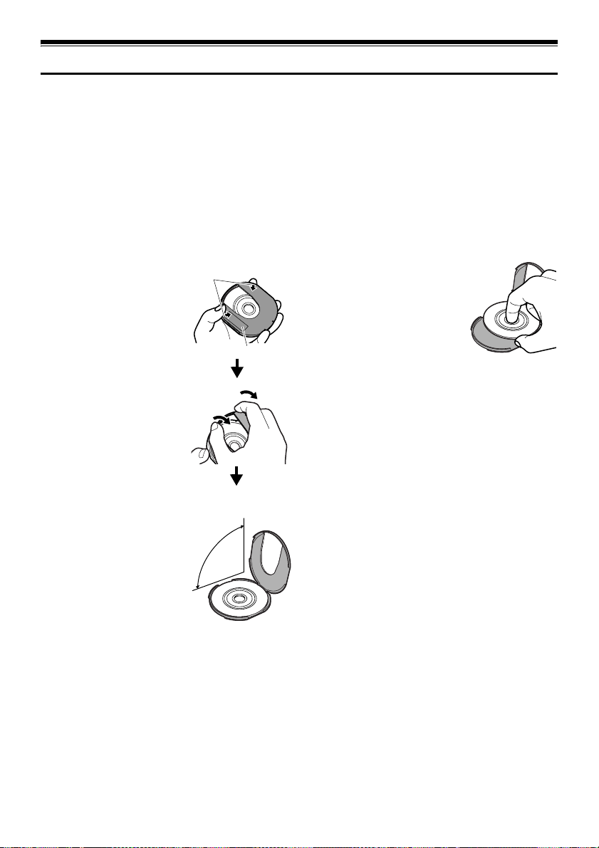
12
Removing from/and Replacing in Round DVD Holder
You can remove a DVD-RAM or a DVD-R disc used in this DVD Video Camera from Round DVD Holder and use
the uncovered disc in DVD player, DVD-RAM recorder, drive for PC, etc., which conforms to 8 cm DVD-RAM or
8 cm DVD-R. Removing disc from Round DVD Holder may vary with the disc maker: See the disc instruction sheet.
The following explains the procedure for removing the disc from and replacing it in the Round DVD Holder made
by Panasonic.
It is recommended that you do not remove the disc from Round DVD Holder until camera recording is finished, in
order to avoid getting dirt on disc.
Note:
Using discs removed from holders on various devices may not always be possible.
How to Remove Disc
1 Hold the Round DVD
Holder with SIDE A facing
up. While pushing the two
release levers in the direction
of arrows (1) marked on
holder, slowly open SIDE A
of the holder in the direction
of arrows (2), taking care not
to drop the disc.
Release
levers
1
SIDE A mark
2
2
Do not open
more than 90°.
2 Without touching the
1
recording/playback surface,
hold the disc edge and center
hole to remove it.
73
Page 74

Replacing Disc in Round DVD Holder
1 Open SIDE A of the Round DVD Holder, and replace
the disc in the holder with the SIDE A mark or label
surface facing up, taking care not to touch the disc
surface.
3
OPEN marks
SIDE A mark side or
Label surface
SIDE A
mark
3
2 Close SIDE A of the Round DVD Holder, and push it
to lock the release levers at positions (3).
When the Hinge of Round DVD Holder Comes Off
1 Push the hinged portion of the holder piece marked
SIDE A with thumb and middle finger, and warp it in
the direction of arrows (4).
SIDE A mark side
Hinged portions
4
Approx. 90°
2 Fit the hinged portion of the other holder piece into
the warped hinge portion.
Note:
• Handle the disc carefully so that no scratches, dirt,
fingerprints or dust adheres to the recording/playback
surface.
• When not using the Round DVD Holder, store it in a case:
Do not leave a bare holder as is.
• Be careful of dropping or impact: If you drop the Round
DVD Holder, the disc may pop out.
• Do not subject the Round DVD Holder to force.
Disc Cleaning
Use a soft, dry cloth to lightly wipe off any dust, dirt, etc.
adhering to disc, as shown in the figure. Never use
solvent. Do not use thinner, water, anti-static spray, etc.
to clean disc.
74
Use soft lint-free cloth to
clean from inner to outer
circumference in axial
direction, or use puffer to
blow dust off disc, like on
camera lens.
Page 75

123
Recording (Dubbing) Images
• Before connecting this DVD Video Camera to another device, be sure to
Before You Begin
Recording (Dubbing) Images from Other Video Device
You can record (dub) images from other video devices to disc or card in this DVD Video Camera.
Use the AV/S input/output cable (provided) to connect the DVD Video Camera to the other AV device as follows:
turn both devices off.
• Insert a recordable disc or card in this DVD Video Camera (see P. 28, 31).
Signal flow
A/V
To AV input/output jack
MIC
AV/S input/output cable
(provided)
* If you are using VDR-M70PP and the connected AV device has an S-VIDEO output jack,
you can connect the S-VIDEO jack of AV/S input/output cable.
1 Set the input source on the
DVD Video Camera to
“LINE (L IN)”.
L IN
0:00:00
REM
3 0 MIN
Switch the input referring to
“Input Source” on page 88.
Choose “S LINE” to input
FINE
8 : 00AM
SEP 30 2 00 4
S-VIDEO signal (Only for VDR-M70PP).
2 Turn on the connected device, and start playback.
The picture will appear on the LCD screen or
viewfinder of this DVD Video Camera.
3 Press the REC button.
Recording will start on this DVD Video Camera.
The operation of this line-input recording is the same
as for recording movie.
Note:
• If you operate the DVD Video Camera connected to
another device, always power the DVD Video Camera
from household AC outlet using the AC adaptor.
• With VDR-M70PP, using S-VIDEO will enable you to
record clearer images.
• The VDR-M50PP cannot record S-VIDEO input.
• Reduce the volume of external input sound heard from
the built-in speaker: The loud volume may cause noise to
enter the recorded image.
To S-video
output jack*
Yellow
White
To video/
audio output
jacks
Red
• The recorded contents can be played back in the same
manner as when playing back camera images recorded
on this DVD Video Camera.
• Still images can also be recorded on DVD-RAM disc or
card. See “Switching External Input Recording Method
(PHOTO Input)” on page 88 for details, and “Recording
Stills” on page 52 for how to record still images.
• The “Input Source” setting will return to “CAMERA”
whenever DVD Video Camera is turned off.
• Recording of most images is prohibited by the copy-
guard signal to protect the copyright, except for images
recorded on camcorders for personal enjoyment. “COPY
PROTECTED” appears in these images: They cannot be
recorded on this DVD Video Camera.
Typical copyright protected images include those of DVD
video, LD, recorded video tapes, some parts of digital
satellite broadcasts, etc.
• If a video signal that cannot be read by this DVD Video
Camera is present - even in images recorded on the DVD
Video Camera for personal enjoyment without copyguard signal - the input image may not be recorded
normally.
• If the input signal is interrupted by switching the channel
on TV or switching the signal using video selector (see
“Ter minology” on page 148), normal recording cannot be
performed.
75
Page 76

Recording (Dubbing) Images from Other Video Cameras
You can record (dub) images from other video cameras on a disc or card in DVD Video Camera. Use the AV/S input/
output cable (provided) to connect the DVD Video Camera to the other video camera.
0:00:00
3 0 MIN
8:00AM
*1
*2
8mm video camera, VHS
video camera, etc.
Note:
• With VDR-M70PP, using S-VIDEO will enable you to
record clearer images.
• Reduce the volume of external input sound heard from
the built-in speaker: The loud volume may cause noise to
enter the recorded image.
• Still images can also be recorded on DVD-RAM disc or
card. See “Switching External Input Recording Method
(PHOTO Input)” on page 88 for details, and “Recording
Stills” on page 52 for how to record still images.
Signal flow
A/V
MIC
AV/S input/output cable (provided)
*1: The AV/S input/output cable provided with this DVD Video Camera can be directly connected to some video
cameras.
*2: For relay adapters, JVC VZ-97 (a set of 3 adapters) and Audio-Technica ATL4C32M and PGF-517 (a set of 2
adapters) are generally available.
*3: If the video camera to be connected has an S-VIDEO output jack, you can connect it to the DVD Video Camera
(VDR-M70PP only).
1 Set the input source on the
DVD Video Camera to
“LINE (L IN)”.
Switch the input referring to
“Input Source” on page 88.
3 relay adapters
(generally available)
To S-VIDEO output jack of
video camera, etc.
FINE
*3
L IN
REM
SEP 3 0 2004
Choose “S LINE” to input S-VIDEO signal (Only
for VDR-M70PP).
2 Turn on the connected device, and start playback.
The picture will appear on the LCD screen or
viewfinder of this DVD Video Camera.
3 Press the REC button.
Recording will start on this DVD Video Camera.
The operation of this line-input recording is the same
as for recording movie.
76
Page 77

Recording (Dubbing) Images on Other Video Devices
You can record (dub) images played back on this DVD Video Camera, onto other video devices.
Use Disc Navigation to create a play list by selecting desired scenes of those recorded on this DVD Video Camera
(P.116).
Use the AV/S input/output cable (provided) to connect the DVD Video Camera to another video device as shown in
the following figure:
Signal flow
A/V
To AV input/output
MIC
jack
AV/S input/output
cable (provided)
* If the video device to be connected has an S-VIDEO input jack, you can connect it to the DVD Video Camera.
1 Press the DISC NAVIGATION button.
To S-VIDEO
input jack of
VCR, etc.*
Note:
Yellow
White
To video/audio
input jacks
Red
• Using S-VIDEO will deliver clearer images.
2 Press the MENU button.
3 Choose “Play” on the “PlayList” menu screen, and
then press the A button.
4 Use the “Start PlayList” screen to select the play list
• Audio is heard from the speaker: If the volume is too high,
noise may enter the dubbed image.
• Be sure to use the AC adaptor to power the DVD Video
Camera from household AC outlet to prevent battery
power from shutting off during recording on another video
device.
to be recorded (dubbed), and then press the record
button on the connected device: The DVD Video
Camera will start playback and the recording device
will record (dub) it.
77
Page 78

Advanced Techniques
This section explains various settings to further extend the usefulness of this DVD Video Camera.
Understanding Flow of Menus
Press the MENU button during recording pause: The “Camera Functions Setup” menu screen will appear.
Tilt the joystick up, down, to the left or the right to select a menu item, and then press the A button to choose the
option.
The screens used here to explain menus are displayed when DVD-RAM disc is used. Some items will not appear when
a DVD-R disc or card is used, or when no disc is inserted.
<Interpreting Setup Screen>
Display of selected
setup item
Selection of setup items
S :Camera Functions
Setup
T :Record Functions
Setup
:Date Setup
V: LCD Setup
W : Initial Setup
Camera Funct i ons Setup
Program AE
W
hi te Bal.
EIS
Dig. Zoo
Wind Cut
Wide
ENTER RETURN
Guide display
Functions settable
WIDE mode will not appear on VDR-M50PP.
When “Wide 16:9” is specified, black bands will appear across
the top and bottom of screen.
* The menu screen, the screen for playing back images
recorded with “Wide 4:3” specified, and Disc Navigation
screen are not set to Wide screen mode.
m
Auto
Sports
Por t r a i t
Spo t l i ght
Surf&Snow
Low L i ght
RAM
Settable
Options
Display of disc or card
being used (P. 55)
78
Page 79

lFlow of Menus
Refer to page indicated for details about each function.
Camera Functions Setup
Camer a Func t i ons Se t up
Program AE :
W
hi te Bal. :
EIS :
Dig. Zoom :
W
ind Cut :
Wide
ENTER RETURN
*1 Not displayed on VDR-M50PP. Displayed on VDR-
:
M70PP only for movies using DVD-RAM disc.
Recording Functions Setup
Record Funct i ons Setup
V I DEO Mo d e : F I NE
I npu t Source : CAMERA
PHOTO I n p u t : F i e l d
S e l f T ime r : O f f
OSD Ou t p u t : On
ENTER RETURN
*2: The quality mode will appear when using card (P. 87)
*3: Displayed when DVD-RAM disc (PHOTO mode) or
card is used, and input selection is set to external
signal or S external signal.
*4: Displayed only with stills
*5: Displayed only when input source is set to
“CAMERA”
Program AE (P. 80)
White balance (P. 81)
Au t o
Au t o
EIS (P. 83)
On
40x
Digital zoom (P. 57)
Of f
4:3
Wind Cut (P. 83)
RAM
Wide
*1
(P. 84)
Movie quality
Input selection (P. 88)
External still input
Self-timer
On-screen information display
RAM
output
*5
(P. 90)
*4
*2
(P. 86)
(P. 89)
*3
(P. 88)
Date Setup
Dat e Se t up
Date Mode : M/D/Y
Da t e Se t
RETURN
ENTER
LCD Setup
LCD Setup
Brightness
Co l or L e v e l
ENTER
RETURN
Initial Setup
Initial Setup
Beep : O n
Po
w
er Save : Of f
Record LED : On
Language : Eng l is h
Reset
ENTER RETURN
Display format (P. 41)
Date setting (P. 40)
RAM
Brightness (P. 91)
Color density (P. 91)
RAM
Beep (P. 92)
Power Save (P. 92)
Recording LED (P. 93)
Language selection (P. 93)
Reset (P. 94)
RAM
You can use the joystick on DVD Video Camera to select various setting options in menu.
Press the MENU button.
Camer a Func t i ons Se t up
ENTER RETURN
Record Funct i ons Setup
ENTER
Au t o
Program AE :
W
hi te Bal. :
Au t o
On
EIS :
Dig. Zoom :
40x
Of f
W
ind Cut :
Wide
:
4:3
V I DEO Mo d e : F I NE
I npu t Source : CAMERA
OSD Ou t p u t : On
RETURN
RAM
RAM
Press the A button directly to choose an option from menu.
To return to the previous screen, press the
Pressing the MENU button again will cause the menu screen to
disappear.
Note:
• Pressing the MENU button during recording will not work.
• The menu screen will disappear when it is left for approx.
1 minute without any operation.
or
Camer a Func t i ons Set up
ENTER RETURN
Program AE
W
hi te Bal.
EIS
Di g. Zoom
W
ind Cut
Wide
Auto
Sports
Por trait
Spo t l i ght
Sur f &Snow
Low L i gh t
RAM
or
C button.
• With VDR-M70PP, if the MENU button is pressed with a
still image displayed, the size of the image will change.
Pressing the MENU button again will restore the original
image size.
79
Page 80

123
Setting Up Camera Functions
Before You Begin
• See page 79 for how to set.
• No menu screen appears with external input.
Selecting Shooting Mode to Match the Subject (Switching Program AE Mode)
This DVD Video Camera automatically sets the shutter speed and aperture according to the subject brightness for
optimum recording: You can also specify one of six modes depending on subject conditions, recording environment
or purpose of filming.
Note:
MENU
Tilt up/down and left/right
to select, and then press
A to designate.
1 Press the MENU button, use the joystick to choose
“Program AE” on the “Camera Functions Setup”
screen, and then press the A button.
The options will appear to the right of “Program AE”.
2 Use the joystick to choose
the desired option, and then
press the A button: The
selected option will be set.
Selected AE mode
Camer a Func t i ons Set up
Program AE
W
hi te Bal.
EIS
Dig .Zoo
m
W
ind Cut
Wide
ENTER RETURN
FINE
Auto
Sports
Por trait
Spo t l i ght
Sur f&Snow
Low L i gh t
0:00:00
REM
8:00AM
30
SEP
30MIN
• You can check the selected AE mode on the on-screen
information display. However, nothing will appear in Auto
mode.
• The shooting mode set as above will be stored in memory
even if the DVD Video Camera is turned off.
a Au to : The DVD Video Camera automatically judges
the subject and surrounding environment for optimum
recording.
Sports : Reduces blurring when recording rapidly
moving subjects such as in golf or tennis.
If the Sports mode is used under a fluorescent light, the
image may flicker: In this case, use the Auto mode for
recording.
Po rtra it : Creates a shallow depth of field so that the
person or subject appears against a softened background.
Spotlight : Prevents overexposure of subject
portrait face, etc. when strong light strikes the subject, as
in a wedding or on stage.
Surf & Snow : Prevents underexposure of subject
portrait face, etc. in a place where reflection of light is
intense, such as at the seaside in midsummer or on a ski
slope.
RAM
Low Light : Allows user to record in a dark place
even with decreased lighting: However, an after-image
will appear with a moving subject.
Note that the Low Light mode cannot be used when the
recording quality mode is STD.
If there is difficulty in automatically focusing subject
image, adjust the focus manually.
2004
3 Press the MENU button to end setting.
The menu screen will disappear.
80
Page 81

Adjusting Color (White Balance)
This DVD Video Camera automatically adjusts the color
of subject. Change the white balance setting depending
on the recording conditions.
Mode Setting contents
Auto White balance always
Set You can manually adjust
automatically adjusted
white balance to match
the light source or
situation
Outdoor To record in fine weather
Indoor To record under
incandescent light,
halogen light or bulbcolor type fluorescent
light
1 Press the MENU button,
choose “White Bal.” on the
“Camera Functions Setup”
menu screen, and then press
the A button.
On-screen
display
None
h
i
j
Camer a Func t i ons Set up
Program AE
W
EIS
Dig .Zoo
W
Wide
ENTER RETURN
hi te Bal.
ind Cu t
Aut o
Set
m
Ou t do o r
Indoor
RAM
2 Choose the desired option,
and then press the A
button.
FINE
0:00:00
REM
SEP
30
30MIN
8:00AM
2004
lSetting white balance manually
1 Point the DVD Video
Camera at a white
object so that it fills the
screen. Use an object
that is not transparent.
If the object that fills
the screen is not
White thick paper
focused, correct the
focus using “Manual
Focus”, P. 64.
2 Press the MENU
button, choose “White
Bal.”, “Set”, and then press
the A button.
Camer a Func t i ons Set up
Program AE
W
hi te Bal.
EIS
Dig . Zoo
m
W
ind Cut
Wide
ENTER RETURN
3 Hold A pressed until the
“h“ indicator changes from
blinking to a steady light.
When the “h“ indicator
lights, the white balance
setting will be complete.
Set EXIT
4 Press the g button to end the
setting.
Aut o
Set
Ou t do o r
Indoor
RAM
RAM
0:00:00
REM
30MIN
White balance mode
3 Press the MENU button to end the setting.
Note:
• The white balance mode can be confirmed using the on-
screen information.
• In Set mode, resetting will be necessary when the DVD
Video Camera is turned off. (All other modes of the white
balance will be stored in memory.)
• If “Input Source: LINE” or “S LINE” has been specified,
you cannot use the “Set” mode of white balance (P. 88).
FINE
SEP
30
8 : 00AM
2004
Note:
• It is recommended that you specify “Dig. Zoom: Off” (See
page 57) before setting white balance.
• Do not use a colored object when setting white balance:
The appropriate tint cannot be set.
• The white balance cannot be set when the digital zoom is
engaged or under low light: The
at this time.
“h” indicator will blink
• If the white balance that was manually set before is kept,
“h” indicator will blink (re-setting the white balance
the
will change the
“h” indicator to a steady light).
81
Page 82

Note:
• Do not block the infrared sensor (see “Terminology” on
page 148) with hand, etc.
Infrared sensor block
• If a optional-user provided tele or wide-conversion lens is
used, the auto white balance may not operate depending
on the recording conditions. If this happens, set the mode
to match the recording conditions, or manually set the
white balance.
• Be sure to remove the lens cap before turning the DVD
Video Camera on: If the DVD Video Camera is turned on
with the lens capped, the white balance will not work
normally.
82
Page 83

Using the Electronic Image Stabilizer (EIS)
When you use zoom to record a magnified subject image, it will correct fuzziness in the recorded image.
1 Press the MENU button,
choose “EIS” on the
“Camera Functions Setup”
menu screen, and then press
the A button.
Camera Funct i ons Setup
Progra
W
hi te Bal.
EIS
Dig.Z
W
ind Cut
Wide
ENTER RETURN
2 Choose “On” or “Off”, and
then press the A button.
3 Press the MENU button to end setting.
oom
m
AE
On
Of f
After recording with EIS set to “Off”, it is recommended
that you return the setting to “On” and then turn the DVD
Video Camera off, unless you normally record with EIS
“Off” setting.
RAM
Note:
• The EIS setting will be stored in memory even when the
DVD Video Camera is turned off.
• It is recommended that you specify “EIS: Off ” when using
the DVD Video Camera on a desk or tripod.
• When “EIS: On” is specified, there will be a slight
difference between the actual movement and the
lChecking whether EIS is On or Off
You can check whether EIS is On or Off by the on-screen
information display.
0:00:00
REM
EIS
30MIN
movement on screen.
• Gross camera shake may not be entirely corrected even
if “EIS: On” is specified. Firmly hold the DVD Video
Camera with both hands.
• EIS may not operate correctly when the tele or wide-
conversion lens (optional-user provided) is used.
• When you record pictures with setting 10x or more of
magnification and turning the EIS to “ON” in dim places,
FINE
SEP
8:00AM
30
2004
after-images may stand out. In this case, we recommend
using a tripod with turning the EIS to “OFF” (only for VDRM50PP).
• The EIS function cannot be used when still images are
recorded on the card (only for VDR-M70PP).
Reducing Wind Noise during Recording (Wind Cut)
When recording sound from the microphone built into this DVD Video Camera, you can reduce wind noise in
recording.
If “Wind Cut: ON” is specified, the low-frequency components in the sound picked up by microphone will be cut off
during recording: This makes it easier to hear the target voice or sound during playback.
1 Press the MENU button,
choose “Wind Cut” on the
“Camera Functions Setup”
menu screen, and then press
the A button.
2 Choose the desired option,
and then press the A button.
3 Press the MENU button to
end setting.
Camer a Func t i ons Set up
Program AE
W
hi te Bal.
EIS
Dig. Zoo
m
W
ind Cut
Wide
ENTER RETURN
FINE
Wind cut icon
On
Of f
RAM
0:00:00
REM
30MIN
8:00AM
SEP 30 2004
Note:
• You can also use the on-screen display to confirm that
Wind Cut has been set.
• The Wind Cut setting will be stored in memory even when
the DVD Video Camera is turned off.
• The Wind Cut function will work only during movie
recording.
• The Wind Cut function works only with the built-in
microphone: It will not function when using an external
microphone (P. 68).
83
Page 84

1
Setting to Wide TV Screen Mode (Wide) (Only for VDR-M70PP)
If you view the images recorded with “Wide 16:9” specified on a wide-screen TV (aspect ratio 16:9), screen image
will be wider than the images recorded with “Wide 4:3” (aspect ratio 4:3) by the size of the areas on left and right
(in dotted lines).
“Wide 4:3” specified
(aspect ratio 4:3)
1 Press the MENU button, choose “Wide” on the
“Wide 16:9” specified
(aspect ratio 16:9)
2 Choose “16:9”, and then press the A button.
“Camera Functions Setup” menu screen, and then
press the A button.
Camera Funct i ons Setup
Program AE
W
hite Bal.
EIS
m
Dig. Zoo
W
ind Cut
4:3
Wide
ENTER RETURN RA
Camera Funct i ons Setup
Program AE
W
hite Bal.
EIS
Dig. Zoo
W
ind Cut 16 : 9
M
Wide
ENTER RETURN RA
3 Press the MENU button to end setting.
m
4:3
M
FINE
Wide 16:9 icon
0:00:00
REM
30MIN
8:00AM
SEP 30 2004
When viewing playback on an ordinary TV screen later, specify “Wide 4:3”: Recording with “Wide 16:9” specified
will be played back on an ordinary TV with vertical elongation of image.
.
An image recorded with “Wide 16:9” specified will appear as follows :
Display on LCD monitor screen
Display in viewfinder (expanded vertically)
84
Page 85

Note:
• The Wide setting will be kept even after the DVD Video Camera is turned off.
• The VDR-M50PP does not have the Wide setting.
• Even if you use the provided application software (MyDVD) and dub wide movies on DVD-RAM disc to DVD-R disc, the
screen image will not be wider. DVD-R disc does not support the Wide setting and it is displayed lengthwise when you
playback this disc.
Before recording movies to the DVD-R disc, set the Wide setting beforehand to “4:3”.
• The Wide 16:9 setting can be used when recording movies on DVD-RAM disc: It is not compatible with still recording,
recording of external input or recording on DVD-R disc.
• Images recorded with “Wide 16:9” (aspect ratio 16:9) specified cannot be restored to “Wide 4:3” setting (aspect ratio 4:3).
• The characters of dates and titles will be longer in the vertical direction on a wide-screen TV and on the LCD monitor
of DVD Video Camera.
• Even if you set the Wide setting at “16:9”, screen image will appear at “4:3” when you press the MENU button and display
the menu screen.
• When you view the image recorded with “Wide 16:9” specified on the television or PC monitor with black bands at the
top and bottom of the picture, flicker may occur between the black bands and the picture.
• The Wide 16:9 setting is not compatible with ID-1/ID-2*.
• Connecting the DVD Video Camera to the S1 input jack of TV will automatically switch the TV to Wide setting: See TV
instruction manual for details.
* This system records the aspect ratio (16:9, 4:3) information in void space between video signals.
85
Page 86

Setting Up Record Functions
12
Switching Movie Quality (VIDEO Mode)
Choose the movie quality from “XTRA” (only with DVD-RAM disc), “FINE”, “STD” and “LPCM” (only with
DVD-R disc).
It is recommended that you record critical subjects in “XTRA” or “FINE” when you are using a DVD-RAM
disc, or in “FINE” with a DVD-R disc.
1 Press the MENU button,
choose “VIDEO Mode” on
the “Record Functions
Setup” menu screen, and
then press the A button.
Record Funct i ons Setup
V I DEO Mode
In pu t Sou r ce
OSD Ou t pu t
ENTER RETURN
2 Choose the desired quality
mode, and then press the A button.
3 Press the MENU button to end the setting.
XTRA
FINE
STD
Note:
• The movie quality setting will be stored in memory even
when the DVD Video Camera is turned off.
• The “VIDEO Mode” setting will not change even if the
DVD-RAM disc is replaced with a DVD-R disc, or vice
RAM
versa. However, the setting will switch to “FINE” in the
following cases:
- When the mode is set to “XTRA” with a DVD-RAM disc
inserted and then the disc is replaced with a DVD-R
disc
- When the mode is set to “LPCM” with a DVD-R disc
inserted and the disc is replaced with a DVD-RAM disc
• When using DVD-R disc, you cannot switch the movie
quality while recording on the disc: The DVD Video
Camera will be automatically set to the movie quality first
used with the disc for recording.
• The movie quality setting is effective only during movie
recording: The setting will not be displayed during
recording of stills.
Movie quality
0:00:00
REM
30MIN
FINE
SEP
8:00AM
30
2004
Block-like noise may appear in recorded image, or the outline of subject image is distorted under the recording
conditions listed below: Pan the DVD Video Camera as slowly as possible. (Block noise is likely to appear in “STD”
mode):
• If there is a complicated pattern in the background (as in figure on botton left)
• If the DVD Video Camera is moved excessively or quickly
• If subject is moving rapidly even when the DVD Video Camera is not moving
(Image when block-like noise occurs) (Image without block-like noise)
86
Page 87

Switching Quality of Still Image (Quality)
You can switch the still recording quality only when using card.
It is recommended that you use “FINE” when recording vital images.
3
1 Press the MENU button,
choose “Quality” on the
“Record Functions Setup”
menu screen, and then press
the A button.
2 Choose the option you want,
and then press the A button.
Record Funct i ons Setup
Quality
In pu t Sou r ce
Sel f Timer
OSD Ou t pu t
ENTER RETURN
FINE
NORM
ECO
3 Press the MENU button to
end setting.
NORM
Still recording quality
Note:
• The still quality setting will be stored in memory even
when the DVD Video Camera is turned off.
• “PHOTO Input” is displayed only when “Input Source” is
set to “LINE” or “S LINE” (VDR-M70PP only).
• “OSD Output” is displayed only when “Input Source” is set
to “CAMERA”.
SEP
REM
30
999
8 : 00AM
2004
87
Page 88
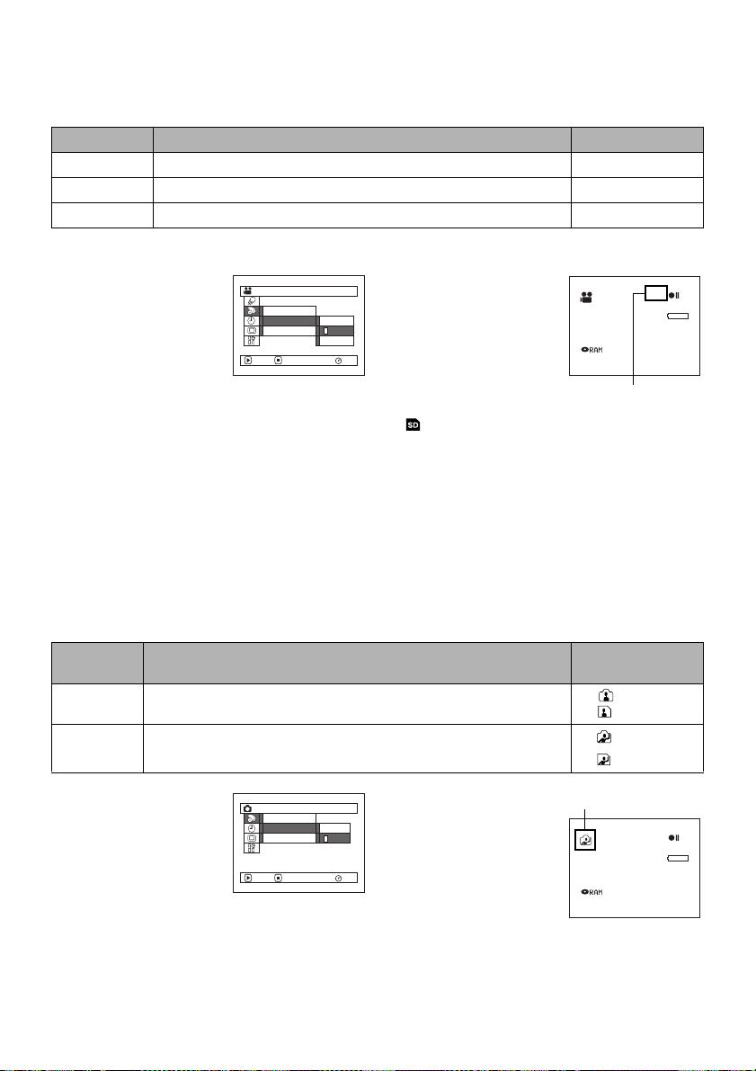
123
Receiving Image from Another Device (Input Source)
If you wish to input an image from another device to this DVD Video Camera, you must first switch the setting on
the DVD Video Camera. Refer to the explanation starting from page 75 on how to connect the DVD Video Camera
to other devices or record images input from them.
Setting Contents On-screen display
CAMERA
LINE
*
SLINE
* Displayed on VDR-M70PP only.
This option usually selected. No display
To input image from another device. L IN
To input S-VIDEO signal from another device. S IN
1 Press the MENU button,
choose “Input Source” on
the “Record Functions
Setup” menu screen, and
then press the A button.
2 Choose “LINE” or “S
LINE”, and then press the A button.
Record Funct i ons Setup
V I DEO Mode
In pu t Sou r ce
OSD Ou t pu t
ENTER RETURN
CAMERA
LINE
S LINE
3 Press the MENU button to
end setting.
Note:
• The “Input Source” setting will
RAM
return to “CAMERA” whenever
the DVD Video Camera is
turned off.
• If you pull or push the card on
“ ” mode, “Input Source” setting will return to
”CAMERA”.
L IN
0:00:00
REM
FINE
External input icon
SEP
30
30MIN
8 : 00AM
2004
• “PHOTO Input” is displayed only when “Input Source” is
set to “LINE” or “S LINE” (VDR-M70PP only).
• “OSD Output” is displayed only when “Input Source” is set
to “CAMERA”.
13
Switching External Input Recording Method (PHOTO Input)
When “Input Source: LINE or S LINE” is specified, you can record stills of externally input images on either a DVDRAM disc or a card. The DVD Video Camera can record an external image with little movement by specifying
“Frame”, but “Field” is recommended for recording an image with movement.
Recording
format
Frame
Field
Does not suit recording of freq uently moving video subjects, despite high
image quality. Frame suits recording of less moving video.
Suitable for recording of frequently moving video subjects. (with disc)
1 Press the MENU button,
choose “PHOTO Input” on
the “Record Functions
Setup” menu screen, and
then press the A button.
2 Select the desired option and
then press the A button.
Details of setting On-screen display
Record Funct i ons Setup
In pu t Sou r ce
PHOTO Input
Sel f Timer
ENTER RETURN
Frame
Field
3 Press the MENU button
to end setting.
RAM
Still external input mode
(with disc)
(with card)
(with card)
L IN
REM
8:00AM
SEP
30
999
2004
88
Page 89

Note:
• The PHOTO Input setting can be confirmed using the on-
screen information.
• The PHOTO Input setting will be stored in memory even
when the DVD Video Camera is turned off.
• Refer to “Recording (Dubbing) Images” on page 75 to
see how to connect the DVD Video Camera to another
device.
• “PHOTO Input” is displayed only when “Input Source” is
set to “LINE” or “S LINE” (VDR-M70PP only).
• “OSD Output” is displayed only when “Input Source” is set
to “CAMERA”.
Self Timer
You can record photos using the self timer function, as with ordinary cameras.
The self timer function is valid only when recording photos (stills).
1 Press the MENU button,
choose “Self Timer” on the
“Record Functions Setup”
menu screen, and then press
the A button.
Recor d Func t i ons Se tu p
Input Source
Se l f T i mer
OSD Ou t pu t
ENTER RETURN
2 Select “On”, and then press
the A button.
The self timer will be set.
3 Press the MENU button to end the setting.
Self timer recording
On
Of f
REM
10
8:00AM
SEP
30
4 Press the REC button.
The recording indicator at the front of DVD Video
Camera will blink.
RAM
999
2004
The Self timer indicator will start to count down, and
recording will commence approximately 10 seconds
later.
Note:
• You can also check that self timer has been set by
reviewing the on-screen information.
• To release the self timer mode, choose “Off” on the menu
screen or turn DVD Video Camera off.
• To suspend self timer, press the REC button again before
recording starts, or press the g button.
• “PHOTO Input” is displayed only when “Input Source” is
set to “LINE” or “S LINE” (VDR-M70PP only).
• “OSD Output” is displayed only when “Input Source” is set
to “CAMERA”.
13
89
Page 90

123
Setting OSD Output On or Off (On-Screen Display)
If you connect this DVD Video Camera to a TV to view images on TV screen, you can switch off the on-screen
information (displayed in the viewfinder or on the LCD screen) from the TV screen.
1 Press the MENU button,
choose “OSD output” on the
“Record Functions Setup”
menu screen, and then press
the A button.
Record Funct i ons Setup
V I DEO Mode
In pu t Sou r ce
OSD Ou t pu t
ENTER RETURN
2 Choose “On” or “Off”, and
press the A button.
3 Press the MENU button to end setting.
“On” setting
0:00:00
REM
30MIN
FINE
TV screen TV screen
SEP
8:00AM
30
2004
Note:
• The “OSD Output” setting will return to “On” whenever
the DVD Video Camera is turned off.
On
Of f
• Even if “Off” is chosen, the on-screen information will
appear during playback. See page 63 for playback on-
RAM
screen information display.
• Even after the on-screen information is removed from the
TV screen, it will still appear in the viewfinder or on the
LCD screen.
• The on-screen display output functions only when the
“Input Source” setting is set to “CAMERA”: It cannot be
set during “LINE” or “S LINE” (VDR-M70PP only).
• “OSD Output” is displayed only when “Input Source” is set
to “CAMERA”.
LCD screen or viewfinder
0:00:00
REM
30MIN
FINE
SEP
8:00AM
30
2004
“Off” setting
90
Page 91

123
LCD Setup
Setting Brightness of LCD Screen (Brightness)
1 Press the MENU button,
choose “Brightness” on the
“LCD Setup” menu screen,
and then press the A
button.
LCD Setup
Bri ghtness
Color Level
ENTER RETURN
3 Press the MENU button to end setting.
Note:
The brightness setting will be stored in memory even when
the DVD Video Camera is turned off.
RAM
The brightness adjustment
bar will appear on the screen.
2 Use the joystick for
adjustment.
Tilt left : The screen
becomes
dimmer
Tilt right :The screen
becomes
brighter
LCD Setup
Bri ghtness
Color Level
ENTERADJUST
Brightness
adjustment bar
RAM
Setting Color Density of LCD Screen (Color Level)
1 Choose “Color Level” on
the “LCD Setup” menu
screen, and then press the
A button.
The color density
adjustment bar will appear
on the screen.
LCD Setup
Bri ghtness
Color Level
ENTER RETURN
3 Press the MENU button to end setting.
Note:
• The color level setting will be stored in memory even
RAM
when the DVD Video Camera is turned off.
• Even if the brightness or density of LCD monitor screen
is changed, the brightness or density of the recorded
image itself will not change.
2 Use the joystick for
adjustment.
Tilt left : For lighter
color
Tilt right :For denser
color
LCD Setup
Bri ghtness
Color Level
ENTERADJUST
Color density
adjustment bar
RAM
91
Page 92

123
Initial Settings
Switching Operating Sound On or Off (Beep)
Setting Contents
On
Off
Beep is heard when the power switch is turned on/off, the REC button is pressed,
etc.
No beep is heard.
2 Select “On” or “Off”, and then press the A button.
1 Press the MENU button,
choose “Beep” on the
“Initial Setup” menu screen,
and then press the A
button.
Turning DVD Video Camera Off Automatically (Power Save)
Setting Contents
On
Off
1 Press the MENU button,
choose “Power Save” on the
“Initial Setup” menu screen,
and then press the A
button.
Ini t ial Setup
Beep
Power Save
Record LED
Language
Reset
ENTER RETURN
To engage power save. If the DVD Video Camera is left in recording pause mode
without being operated for 5 minutes, it will automatically turn off to prevent the
battery from discharging needlessly.
To cancel power save.
Ini t ial Setup
Beep
Power Save
Record LED
Language
Reset
ENTER RETURN
On
Of f
On
Of f
3 Press the MENU button to end setting.
Note:
The “Beep” setting will be stored in memory even when the
RAM
DVD Video Camera is turned off.
Note:
• To turn the DVD Video Camera on again from automatic
off activated by the power save function, set the power
switch to “OFF”, and then set it to “ ”, “ ” or “ ”.
• The Power Save setting will not appear in the on-screen
information display.
• The Power Save setting will be stored in memory even
RAM
when the DVD Video Camera is turned off.
2 Select “On” or “Off”, and
then press the A button.
3 Press the MENU button to end setting.
92
Page 93

Turning Record LED On or Off (Record LED)
You can switch off the recording indicator on the front of DVD Video Camera even during recording.
Setting Contents
On
Off
The recording indicator will light red to show that the DVD Video Camera is recording.
The recording indicator will not light even during recording.
2 Select “On” or “Off”, and then press the A button.
3 Press the MENU button to end setting.
Recording indicator
1 Press the MENU button,
choose “Record LED” on
the “Initial Setup” menu
screen, and then press the
A button.
Ini t ial Setup
Beep
Power Save
Record LED
Language
Reset
ENTER RETURN
On
Of f
Changing Display Language (Language)
You can change the language used to display the menu and information.
The following shows that English has been changed to French.
Note:
• The Record LED setting will not appear in the on-screen
information display.
• The Record LED setting will be stored in memory even
when the DVD Video Camera is turned off.
• Specify “Record LED: Off” when recording a subject
behind glass or a water tank that reflects light: The
reflected light of a recording indicator will not be
recorded.
• When using the self timer function, the recording
indicator will blink when the REC button is pressed
RAM
regardless of whether Record LED is On or Off.
1 Press the MENU button,
choose “Language” on the
“Initial Setup” menu screen,
and then press the A
button.
2 Select “Français”, and then
press the A button.
Ini tial Setup
Beep
Power Save
Record LED
Language
Reset
ENTER RETURN
Configuration Ini t iale
Bip
Éne rg i e
DEL En r eg.
Langue
Régl . Dé f aut
ENTRER RETOUR
Engl i sh
Français
Español
Deutsch
Italiano
Français
3 Press the MENU button to end setting.
Note:
The language setting will be stored in memory even when
the DVD Video Camera is turned off.
RAM
RAM
93
Page 94

Resetting Menu Settings to Defaults (Reset)
You can restore menu settings to defaults [initial settings at the factory (P. 164)].
1 Press the MENU button,
choose “Reset” on the
“Initial Setup” menu screen,
and then press the A
button.
The screen for verifying
reset will appear.
2 If you are sure that you wish
to reset, use the joystick to
choose “YES”, and then
press the A button.
The settings have now been
reset to defaults.
Ini t ial Setup
Beep
Power Save
Record LED
Language
Reset
ENTER RETURN
Reset
Reset?
YES NO
ENTER
3 Press the MENU button to end setting.
Note:
To cancel resetting midway, choose “NO” on the verification
screen in step 2 or press the g button.
RAM
RAM
94
Page 95

Disc Navigation
123
Using Disc Navigation
Starting or Terminating Disc Navigation
Disc Navigation is a tool for editing scenes recorded on this DVD Video Camera.
Following is an explanation of “scene” and “program” so that you will be able to make the most use of the Disc
Navigation function.
The screens in this operating manual are basically those that will appear when DVD-RAM disc is used: Some items
will not appear when DVD-R disc or card is used, but the operations are the same.
• Turn the DVD Video Camera on (P.50).
Before You Begin
1 Press the DISC NAVIGATION button.
The Disc Navigation screen (shown on page 96) will
appear.
• When using disc: Set the power switch to “ ” or “ ”.
• When using card: Set the power switch to “ ”.
2 Press the DISC NAVIGATION button.
Disc Navigation will be terminated and the DVD
Video Camera will enter recording pause mode.
You can also press the g button to end Disc
Navigation.
95
Page 96

The following screen will appear when DVD-RAM disc is used: Some display components will not appear when
DVD-R disc or card is used.
Thumbnail (see “Terminology” on page 148)
001/ 014All Programs
Cursor
Still image icon
Operation guide
*1
Scene number refers to display number on thumbnail display screen.
*2
No still icon will appear for card.
*3
The operation guide will vary depending on the operation status of DVD Video Camera.
*4
Appears when 13 scenes or more have been recorded.
*5
“ R” appears for DVD-R disc. “ ” will appear for card.
Note:
*2
*3
PLAY
RAM
• The background color of screen allows you to identify
whether disc or card is in DVD Video Camera.
- Purple: When disc is inserted
- Light blue: When card is inserted
• Pressing the DISPLAY button will display the recording
date/time of the scene on which the cursor is placed in the
space for operation guide. Pressing DISPLAY again will
display the operation guide.
• If no disc or card is inserted, the Disc Navigation screen
cannot be displayed even by pressing the DISC
NAVIGATION button.
• Each time Disc Navigation is started with a DVD-R disc
inserted, message “Creating Thumbnail ...” will appear.
After the message appears, the Disc Navigation screen
will appear.
• If the following type of disc or card is inserted, the Disc
Navigation screen will appear or some message will be
displayed:
- Write-protected disc
- Locked card
- Finalized DVD-R disc
• Do not leave the disc navigation screen displayed on TV
to which the DVD Video Camera is connected: Doing so
could result in displayed image retention or phosphor
degradation of TV screen.
Selected scene number*1/
Total number of scenes
Current page position
Bar graph
Disc type icon
*4
*5
96
Page 97

Playing Back from Disc Navigation Screen
1 Press the DISC NAVIGATION button.
2 Use the joystick to select the desired scene.
The selected scene will be framed: This is called a
“cursor”.
001/014All Programs
Up or Down
PLAY
lWhen playback ends
The DVD Video Camera will
enter playback pause mode at
the last image of last scene.
Pressing the g or DISC
NAVIGATION button will
restore the Disc Navigation
screen.
If playback pause continues for
as long as 5 minutes, the Disc Navigation screen will
automatically be restored.
lPlaying back stills
A still will be displayed for approx. 3 seconds.
When playing back stills on card, playback will stop after
each still playback.
RAM
Left or Right
PLAY
Playback pause
3 Press the A button.
Playback will start from the selected scene.
Note:
Tilting the joystick to left or right will move the cursor to
the preceding or following scene.
Tilting it up or down will move to preceding or following
page.
007/014All Programs
RAM
A
Note:
• Press the A button to temporarily stop playback.
Pressing A again will start from that point.
• If you press the A button after playback of the last
scene on disc finishes, playback will start again from the
beginning of disc.
• Pressing the g button will always restore the Disc
Navigation screen.
• When playing back a still with a large number of pixels on
card, “Playback.” will appear, and it will take some time for
the still to appear.
97
Page 98

Selecting Multiple Scenes
1 Press the DISC NAVIGATION button.
2 Use the joystick to select the desired scene.
3 Press the SELECT button once:
The selected scene will be framed in red and yellow.
Selecting Consecutive Scenes Together
1 Press the DISC NAVIGATION button.
2 Use the joystick to select the
desired scene.
3 Hold down the SELECT
button for at least one
second:
The selected scene will be
doubly framed in yellow
and blue.
4 Use the joystick to select
the last scene in the range
you want, and then press the
A button:
The thumbnails of scenes in
the specified range will be
framed in red, and then
selected.
PLAY
Yellow frame
ENTER CANCEL
Double frames in
yellow and blue
PLAY DESELECT ALL
Red
frame
When scenes up to this
point are selected
005 / 014All Programs
RAM
005 / 014All Programs
RAM
010/ 014All Programs
RAM
Repeat steps 2 and 3 to randomly select multiple
scenes.
To cancel a selected scene, select the scene to be
canceled, and then press the SELECT button.
To cancel all selected scenes, press the g button.
Note:
Although scenes can be randomly selected, playback will
always start from the lowest scene number.
Note:
• You can know the status of scenes from the colors of
cursor and bar graph:
Cursor Bar graph Status of scenes
Yellow Light blue
Blue Light blue
Red Red
• Pressing the A button after selecting scenes will play
back only the selected scenes from the beginning of each
scene.
• You can also select scenes in reverse from the last scene
in the range.
• To release multiple selection, press the SELECT or g
button after step 4.
• Up to 999 scenes can be selected for both disc and card.
Current cursor position
Range of scenes being
selected
Scenes already selected
98
Page 99

Disc Navigation Menu
Functions Available with Disc Navigation
Disc Navigation allows you to do the following:
Function Disc or card used Contents
Deletion of scenes
Editing of scenes
Scene information
display
Setting of title
Creation of play list
Disc or card initialization
Copy from disc to card
Disc finalization
Repeat play
Slide show
Remaining capacity
Disc protection
Scene lock
DPOF setting
13
1
123
1
1
13
1
2
12
3
123
1
3
3
You can delete unnecessary scenes. 101
You can attach fade and skip to a scene,
combine scenes, or divide one scene.
You can display information on one scene
or multiple scenes, such as image quality,
recording time, etc.
You can set desired titles to play lists and
programs.
You can create an original movie by
changing the combination of scenes.
You can ini tialize a DVD-RAM disc or card
so that it can be used on this DVD Video
Camera.
You can copy photos recorded on DVDRAM disc to card.
You can use this DVD Video Camera to
finalize any DVD-R disc recorded on it so
that the disc can be viewed on DVD
player, etc.
You can repeatedly play back programs
and scenes.
You can play back stills continuously. 129
The remaining recordable movie time or
number of recordable stills is displayed.
You can protect the DVD-RAM disc to
prevent deletion or editing by mistake.
You can lock any scene so that it will not
be deleted by mistake: Essential scenes
are thereby protected, and recording
another still is possible.
You can set print information. 110
Reference
page
103 - 107
112
114, 122
116
125
108
127
128
124
124
109
Note:
Editing functions (thumbnail, skip, fade) are unique to this DVD Video Camera. When a disc edited on this DVD Video
Camera is directly played back on a DVD-RAM recorder or read into PC, the editing results will not be reflected in the
playback or reading. To reflect the editing results, connect both devices using the AV/S input/output cable and then perform
recording (dubbing).
99
Page 100

Understanding Flow of Disc Navigation Menu
Press the MENU button on the Disc Navigation screen: The menu screens for Disc Navigation and menu screens for
disc and card will appear.
See pages 78-79 and 95 for how to interpret the screen.
Refer to pages indicated for details.
lWhen using DVD-RAM disc
Scene
Play list Top (P.123)
Program
Delete (P.101)
Edit
Copy (P.108)
Select (P.111)
Detail (P.112)
Switch (P.117)
Play (P.117)
Create (P.116)
Edit (P.118 - 121)
Title (P.122)
Delete (P.122)
Switch (P.113)
Play (P.114)
Title (P.114)
Thumbnail (P.103)
Skip (P.104)
Fade (P.105)
Combine (P.106)
Divide (P.107)
Move* (P.104)
Start → Current (P.111)
Current → End (P.111)
All (P.111)
Go To
Disc
Others
ETC
* Will appear when a play
list is displayed.
End (P.123)
Capacity (P.124)
Protect Disc (P.124)
Format Disc (P.125)
Update Control Info. (P.126)
Category (P.128)
Repeat Play (P.128)
lWhen using DVD-R disc
Scene
Select (P.111)
Detail (P.112)
Start → Current (P.111)
Current → End (P.111)
All (P.111)
Program
Go To
Switch (P.113)
Play (P.114)
Top (P.123)
End (P.123)
lWhen using card
Scene
Go To
Card
Delete (P.101)
Lock (P.109)
DPOF (P.110)
Select (P.111)
Detail (P.112)
Top (P.123)
End (P.123)
Capacity (P.124)
Format Card (P.125)
100
Disc
Others
ETC
Start → Current (P.111)
Current → End (P.111)
All (P.111)
Slide Show
Capacity (P.124)
Finalize Disc (P.127)
Repeat Play (P.128)
All (P.129)
DPOF (P.129)
 Loading...