

Page 1

DVD Video Camera/Recorder
• VDR-M30PP
VDR-M30EG
VDR-M30B
VDR-M30EN
VOL.1
(PP) or“TYPE PP” and (EG) or“TYPE EG” in this
manual stands for the model shown below.
(PP) or“TYPE PP”: VDR-M30PP (NTSC)
(EG) or“TYPE EG”: VDR-M30EG/B/EN (PAL)
© 2003 Matsushita Electric Industrial Co., Ltd. All rights reserved. Unauthorized
copying and distribution is a violation of law.
Page 2

Table 2-1-1 shows the method for servicing each circuit board and each unit.
Refer to "4 Troubleshooting" for the method of judging defects in each circuit board and each unit.
Information:
These servicing methods are subject to change without notice for the purpose of facilitating service
procedures.
Table 2-1-1 Circuit Board and Unit Servicing
Method
Circuit board/Unit
AEL circuit board
DRF circuit board
DRV circuit board
FAF circuit board
FRT circuit board
GYR circuit board
HDM circuit board
LCD circuit board
MAN circuit board
MR circuit board
SAF circuit board
SHE circuit board
SID circuit board
USB circuit board
Disc drive unit
Servicing method
Component replacement.
Unit replacement.
Included in disc drive unit.
Unit replacement.
Component replacement.
Included in disc drive unit.
Component replacement.
Circuit board assembly
replacement (Order format).
Unit replacement.
Included in disc drive unit.
Unit replacement.
Unit replacement (Order
format). Which incorporates
the DRV, SID and HDM
circuit boards.
LCD
CIRCUIT
BOARD
DISC
DRIVE UNIT
AEL
CIRCUIT
BOARD
FAF CIRCUIT
BOARD
GYR
CIRCUIT
BOARD
USB
CIRCUIT
BOARD
MR
CIRCUIT
BOARD
FRT
CIRCUIT
BOARD
SHE
CIRCUIT
BOARD
DRF
CIRCUIT
BOARD
MAN
CIRCUIT
BOARD
SAF
CIRCUIT
BOARD
Fig. 2-1-1 External Views of the Circuit Board/Unit
Page 3
Slim & Compact
The volume of VDR-M30 series body has been
reduced to approximately half that of the
previous VDR-M20 series, by using a compact
disc drive unit, increasing the parts mounting
density on circuit boards while decreasing the
number of circuit boards, and using a round
DVD holder and compact zoom lens.
Complying with SD memory card/
MultiMediaCard:
The previous models could record photos only
on DVD-RAM disc, but the VDR-M30 can also
record them on SD memory card and
MultiMediaCard (sometimes referred to as “a
card” hereafter).
The VDR-M30 can also copy to a card photos
recorded on DVD-RAM disc.
The VDR-M30 adopts the DCF standard*1 and
complies with DPOF*1 so that photos recorded
on card can be utilized on various devices.
*1: Refer to "3-2-2 Standards for recording photos
on card" for details on DCF standard and
DPOF.
VDR-M30 Series
VDR-M20 Series
Fig. 2-2-1 Reduced Body Volume
Round DVD holder
DVD-RAM/
DVD-R disc
Card (SD memory card/
MultiMediaCard)
PC connection kit/software for editing
provided:
The VDR-M30 is provided with the PC
connection kit and editing software, which were
optional accessories with previous models.
Connecting to PC and editing on it are easy.
Fig. 2-2-2 Media Storage Available on
VDR-M30
Page 4

Specifications are subject to change without notice for the purpose of improvement.
Item
Power source
Power consumption
CCD
Lens
Focus
Zoom
Required minimum
illumination
Viewfinder
LCD monitor
Image Stabilizer
Shutter speed
Self-timer recording
External microphone jack
Recording mode
Maximum
recordable
time
(per side)
Maximum
number of
recordable
photos
DVD-RAM disc
DVD-R disc
DVD-RAM disc
(per side)
Card
VDR-M30PP
DC7.9/7.2V
Recording 5.8W
1/4-inch interlaced
Total number of pixels:
Approx. 680,000
Number of effective pixels:
Video: Approx. 340,000
Photo: Approx. 310,000
F1.8 - 2.5, f = 1/8 - 1-1/4 (3.15 - 31.5
mm)
Filter diameter: 1-3/16 (30.5 mm)
Auto/Manual
Optical 10×, 40 - 240× with digital
zoom added (40× for photo)
12 lx (3 lx: When Low Light mode is
selected)
0.44-inch color TFT
(approx. 110,000 pixels)
2.5-inch color TFT
(approx. 1,200,000 pixels)
Electronic Type
1/60 - 1/4000 (video)
Photo recording only
Ø 3.5 mm stereo mini-jack
Video (with audio)
Photo (DVD-RAM disc, SD memory
card, MultiMediaCard)
XTRA mode: Approx. 18 min.
FINE mode: Approx. 30 min.
STD mode: Approx. 60 min.
FINE mode: Approx. 30 min.
STD mode: Approx. 60 min.
LPCM mode: Approx. 30 min.
999 (However, if video and photo are
mixed on one disc, the recordable
number will decrease)
Varies depending on the recording
quality and the type of card
VDR-M30EG/B/EN
DC7.9/7.2V
Recording (FINE)
4.7W (When using Viewfinder)
5.7W (When using LCD Monitor)
1/4-inch interlaced
Total number of pixels:
Approx. 800,000
Number of effective pixels:
Video: Approx. 410,000
Photo: Approx. 410,000
F1.8 - 2.5, f = 3.15 - 31.5 mm
Filter diameter: 30.5 mm
Auto/Manual
Optical 10×, 40 - 240× with digital
zoom added (40× for photo)
12 lx (3 lx: When Low Light mode is
selected)
0.44-inch color TFT
(approx. 110,000 pixels)
2.5-inch color TFT
(approx. 1,200,000 pixels)
Electronic Type
1/50 - 1/4000 (video)
Photo recording only
Ø 3.5 mm stereo mini-jack
Video (with audio)
Photo (DVD-RAM disc, SD memory
card, MultiMediaCard)
XTRA mode: Approx. 18 min.
FINE mode: Approx. 30 min.
STD mode: Approx. 60 min.
FINE mode: Approx. 30 min.
STD mode: Approx. 60 min.
999 (However, if video and photo are
mixed on one disc, the recordable
number will decrease)
Varies depending on the recording
quality and the type of card
Page 5

Item VDR-M30PP VDR-M30EG/B/EN
Recording
format
Audio playback format
Recording media
Jacks
DVD-RAM disc
DVD-R disc
Card
Video: Conforming to DVD video
recording format (MPEG 1
Audio layer 2)
Photo: Simultaneous recording,
conforming to DVD video
recording format (704 × 480
pixels) and JPEG (640 × 480
pixels)
Video: Conforming to DVD video
format (MPEG1 Audio layer 2
or Linear PCM
(*1)
selected)
Photo: Conforming to JPEG (640 ×
480 pixels) standard
MPEG1 Audio layer 2, Linear PCM,
Dolby AC3
8 cm DVD-RAM disc (conforming to
DVD-RAM Ver. 2.1)
8 cm DVD-R disc (conforming to
DVD-R for General Ver. 2.0)
SD memory card
MultiMediaCard
Video/audio input/output × 1
External microphone input × 1
USB terminal (connected
to PC USB port) × 1
Video: Conforming to DVD video
recording format (MPEG 1
Audio layer 2)
Photo: Simultaneous recording,
conforming to DVD video
recording format (704 × 576
pixels) and JPEG (640 × 480
pixels)
Video: Conforming to DVD video
format (MPEG1 Audio layer
2)
Photo: Conforming to JPEG (640 ×
480 pixels) standard
MPEG1 Audio layer 2, Dolby AC3
8 cm DVD-RAM disc (conforming to
DVD-RAM Ver. 2.1)
8 cm DVD-R disc (conforming to
DVD-R for General Ver. 2.0)
SD memory card
MultiMediaCard
Video/audio output × 1
External microphone input × 1
USB terminal (connected
to PC USB port) × 1
USB
Battery system
Dimensions (W × H × D,
excluding projections)
Operating temperature
(humidity)
USB2.0 compliant (max. 12Mbps)
Lithium-ion
Approx. 2.24 × 3.5 × 5.28 inch
(57 × 89 × 134 mm)
32-104°F (0-40°C) (less than 80%)
32-86°F (0-30°C) when connected to
USB2.0 compliant (max. 12Mbps)
Lithium-ion
Approx. 57 × 89 × 134 mm
0-40°C (less than 80%)
0-30°C when connected to PC
PC
Storage temperature
Weight (excluding battery and
-4 - 104°F (-20 - 60°C)
Approx. 1.058 lbs (480 g)
-20 - 60°C
Approx. 480 g
disc)
Total weight when recording
Approx. 1.246 lbs (565 g) (when using
Approx. 565 g
CGA-DU14A battery pack)
Provided accessories
AC adapter/charger, battery pack,
AV/S input/output cable, remote
controller, button type battery for
remote controller, lens cap, lens cap
string, shoulder belt, power cable, DC
cord, ferrite core, software CD-ROM,
USB cable, 8cm DVD-RAM disc (in
round DVD holder)
AC adapter/charger, battery, AV/S
output cable, infrared remote control,
Lithium battery for remote control,
lens cap, lens cap string, shoulder
strap, mains lead, DC power cord,
ferrite core, software CD-ROM, USB
cable, 8cm DVD-RAM disc (in round
DVD holder)
*1: The VDR-M30PP records audio on DVD-R disc using the MPEG1 Audio layer 2 format in FINE or STD
mode, and using the Linear PCM format in LPCM mode.
The MPEG1 Audio layer 2 format is an option of DVD video format. Record a DVD-R disc in LPCM mode
to play it back on a DVD player that does not comply with this option standard.
Page 6

Item
Switching on-screen language
Full Auto button
Disc protect
Camera
functions
Disc record
functions
Card record
functions
Minimum distance
for recording
Program AE
White balance
Digital zoom
Cinema
Wind cut
Exposure
correction
Backlight
correction
Input selection
External photo
input
Number of pixels
for video (MPEG2)
Number of pixels
for photo during
camera recording
Number of pixels
for photo during
line-input
recording
Copying photos to
card
Input selection
External photo
input
Number of pixels
on photo
File size of photo
VDR-M30PP
English/French/German/Spanish/
Italian
Equipped
Software disc-protect
Wide-angle side: Approx. 2 cm
Telephoto side: Approx. 1 m
Auto/Sports/Portrait/Spotlight/
Surf&Snow/Low Light
Auto/Set/Outdoor/Indoor 1/Indoor 2
240×/40×/Off
-------------------------On/Off
Exclusive button equipped
(Auto/Manual)
Exclusive button equipped
CAMERA/LINE (analog video signal
input from external device)
Frame/Field
XTRA/FINE: 704 × 480 pixels
STD/LPCM: 352 × 480 pixels
JPEG: 640 × 480 pixels
MPEG: 704 × 480 pixels
JPEG: 640 × 480 pixels
MPEG: 704 × 480 pixels
Enable on Disc Navigation function
CAMERA/LINE (analog video signal
input from external device)
Frame/Field
JPEG: 640 × 480 pixels
FINE: Approx. 128KB
NORM: Approx. 64KB
ECO: Approx. 32KB
VDR-M30EG/B/EN
English/French/German/Spanish/
Italian
Equipped
Software disc-protect
Wide-angle side: Approx. 2 cm
Telephoto side: Approx. 1 m
Auto/Sports/Portrait/Spotlight/
Surf&Snow/Low Light
Auto/Set/Outdoor/Indoor
240×/40×/Off
On/Off
On/Off
Exclusive button equipped
(Auto/Manual)
Exclusive button equipped
--------------------------
--------------------------
XTRA/FINE: 704 × 576 pixels
STD: 352 × 576 pixels
JPEG: 640 × 480 pixels
MPEG: 704 × 576 pixels
JPEG: 640 × 480 pixels
MPEG: 704 × 576 pixels
Enable on Disc Navigation function
--------------------------
--------------------------
JPEG: 640 × 480 pixels
FINE: Approx. 128KB
NORM: Approx. 64KB
ECO: Approx. 32KB
Page 7

Jacks
Disc
Navigation
function
Item VDR-M30PP VDR-M30EG/M30B/M30EN
Video/audio input/
output
External
microphone
PC connection
Accessory shoe
With disc
10-pin exclusive input/output
terminal [S (output only)/video/audio
L/audio R] × 1
Ø 3.5 mm stereo × 1
Type B (mini USB)
Power/control terminal not provided
Scene Delete [RAM]
Playlist
[RAM]
Program Switch [RAM/R]
Go To
[RAM/R]
Disc
ETC. Other
settings
Edit [RAM]
Copy [RAM]
Select
[RAM/R]
Detail [RAM/R]
Switch
Play
Create
Edit
Title
Delete
Play [RAM/R]
Title [RAM]
To p
End
Capacity [RAM/R]
Protect Disc [RAM]
Format Disc [RAM]
Update Control Info. [RAM]
Finalize Disk [R]
Category [RAM]
Repeat Play [RAM/R]
Thumbnail
Skip
Fade
Combine
Divide
Move
Start -> Current
Current -> End
All
10-pin exclusive output terminal [S/
video/audio L/audio R] × 1
Ø 3.5 mm stereo × 1
Type B (mini USB)
Power/control terminal not provided
Scene Delete [RAM]
Playlist
[RAM]
Program Switch [RAM/R]
Go To
[RAM/R]
Disc
ETC. Other
settings
Edit [RAM]
Copy [RAM]
Select
[RAM/R]
Detail [RAM/R]
Switch
Play
Create
Edit
Title
Delete
Play [RAM/R]
Title [RAM]
To p
End
Capacity [RAM/R]
Protect Disc [RAM]
Format Disc [RAM]
Update Control Info. [RAM]
Finalize Disk [R]
Category [RAM]
Repeat Play [RAM/R]
Thumbnail
Skip
Fade
Combine
Divide
Move
Start -> Current
Current -> End
All
With card
Scene Delete
Go To
Card
Slide Show
Lock
DPOF
Select
Detail
To p
End
Capacity
Format Card
All
DPOF
Start -> Current
Current -> End
All
Scene Delete
Go To
Card
Slide Show
[RAM/R]: Operable with both DVD-RAM and R discs
[RAM]: Operable with DVD-RAM disc only
[R]: Operable with DVD-R disc only
Lock
DPOF
Select
Detail
To p
End
Capacity
Format Card
All
DPOF
Start -> Current
Current -> End
All
Page 8

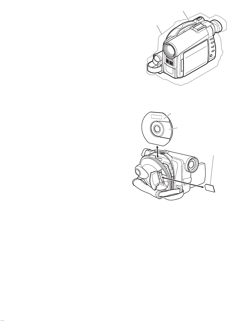
(1) Inserting disc to DVD video camera/recorder
1 Press down the DISC EJ ECT button once and
release it.
A few moments af ter the ACCESS/PC indi cator
blinks, the cover of disc inser tion block w il l open
slightly.
DISC EJECT
button
2 Gently op en th e cover by ha nd until it stops.
3 Inser t the di sc , in Round DVD Hold er, into the
disc guide until it sto ps.
Note that the recording/playback sur face of
di sc must face the inside of DVD vid eo camera/
recorder. The orientation f or inserting the disc
into the disc guide is also predetermined: Load
the disc correctly, referring to the figure.
4 Push the section marked “PUSH CLOSE” on
the cover of disc inser tion bloc k, to close the
co ver .
5 Turn t he DVD video camera /rec order on
( VI DEO or PHOTO).
When “DISC ACCESS” disappears, the DVD
vid eo camera/recorder is ready for recording.
Identifying recording/playback
sides of disc :
Single sided disc:
The recording/playback side
is opposi te to the prin ted label.
Double -sided disc :
The recording/playbac k side
of “ SIDE A” is opposi te to the
“SIDE A” marked side.
The recording/playback si de
of “SIDE B” is the “SIDE A”
marked side.
“SIDE A” mark
The opposite side is
the “SIDE A”
recording/playback
side.
Disc cover
PUSH CLOSE
portion
Disc
guide
Correct
orientation
Incorrect orientation
Incorrect
orientation
(2) Removing disc from round DVD holder
1
Hold the Round DVD Holder with SIDE A facing u p. While pushing the two release levers in
marked on hold er, sl owl y open SIDE A o f the ho lder i n the di recti on of arrows (2), taking c are not to dro p th e disc .
2
Without touching the recording/playback surface, hold the disc edge and center hole to remove it.
Release
levers
1
1
2
SIDE A mark
2
Do not open
more than 90˚.
the direction of arrows (1)
Page 9

(3) Replacing disc in round DVD holder
1
Open SIDE A of the Round DVD Holder, and replace the disc in
the hold er with the SIDE A mark or label sur face facing up,
taking care not to touc h the disc sur fac e.
2
Close SIDE A of the Round DV D Holder , and pu sh it to lock the
releas e levers at p ositions (3).
(4) When the hinge of round DVD holder comes off
OPEN marks
SIDE A mark s ide or
Label surface
3
SIDE A
mark
3
1 Push the hinged portion of the holder piece marked SI DE A with
thumb and middle finger, an d warp it in the direct ion of arrows (4).
2 Fit the hinged porti on of the other holder piece in to the war ped
hinge por t ion.
Note
:
•
Handle the disc carefully so that no scratch, dirt,
to the recording/playback
•
When not usingthe Round DVD Holder, storeit in case:
Do not leave a bare holder as is.
•
Be careful of drop or impact: If you drop the Round DVD Holder, the disc may
pop out.
•
Do not subject the Round DVD Holder to force.
surface.
fingerprint or dust adheres
SIDE A mark side
Hinged portions
4
Approx. 90˚
Page 10

Index
Abbreviation/Term
A
AC3
C
CPRM
D
DCF
Dolby AC3
DPOF
DVD
DVD Forum
DVD-Audio
DVD-R
DVD-RAM
DVD-ROM
DVD-RW
DVD-Video
DVD Video
Format
DVD Video
Recording Format
E
Exif
F
FireWire
I
IEEE1394
Interlaced CCD
i-LINK
J
JEIDA
JEITA
JPEG
L
LCD
LPCM
M
MMC
MMCA
Explanation
See Dolby AC3.
Content Protection for Recordable Media: Security technology (cross-certification
technology) for SD memory card.
Design rule for Camera File system standard: This camera file system standard,
established by JEIDA (now merged to JEITA).
Audio coding format developed by Dolby Laboratories in U.S, also simply referred
as AC3 format: Supports 5-channel full-range sound and one channel for sub-woofer
sound playback.
Digital Print Order Format: DPOF allows user to record print information along
with photos on storage media to facilitate printing of photos.
Digital Versatile Disc. A huge amount of digital data for video (movie) and audio
can be recorded on this disc, whose size is the same as CD.
International organization that formulates the technical standards of DVD
One type of DVD standard disc, on which high-quality audio can be recorded
One type of DVD standard disc, to which writing once is possible (recordable type)
One type of DVD standard disc, to which writing up to 100,000 times is possible
One type of DVD standard disc, to which data for computer can be recorded
One type of DVD standard disc, to which writing up to 1000 times is possible
One type of DVD standard disc, on which high-quality video and audio can be
recorded
Video recording/playback standard that applies to DVD-Video, DVD-R and DVDRW
Video recording/playback standard that applies to DVD-RAM and DVD-RW: This
allows versatile editing functions, differing from the DVD Video Format.
Exchangeable image file format. File format used for recording photos on digital
cameras, established by JEIDA (now merged to JEITA).
See IEEE1394.
Also referred to as FireWire or i-LINK: Standard for serial interface that connects
PC and peripheral devices
This CCD scans one image twice (scans roughly once and interpolates between first
scanning lines the second time) and interlaces the images obtained by scanning
twice to create a one-image signal.
See IEEE1394.
JEIDA stands for Japan Electronic Industry Development Association.
JEITA stands for Japan Electronics and Information Technology Industries
Association, which came into existence when JEIDA merged with EIAJ (Electronic
Industries Association of Japan).
JEITA has established Exif and DCF standard.
Joint Photographic Expert Group: International standard format for compressing
still images
Liquid Crystal Display. LCD formats include STN and TFT.
Linear Pulse Code Modulation. Also referred to as linear PCM. LPCM is a format
that digitizes analog audio data during recording and converts it to analog data
during playback.
See MultiMediaCard.
See MultiMediaCard Association.
Page 11

Index Abbreviation/Term Explanation
M
MPEG
MPEG 1 Audio
Layer 2
MultiMediaCard
MultiMediaCard
Association
OSTA
O
S
SCSI
SDA
SD Card
Association
SDMI
SD Memory Card
SecureMMC
Secure
MultiMediaCard
Software discProtect
STN LCD
T
TFT LCD
U
UDF
USB
V
VBR
Motion Picture Experts Group: Standard related to compression of digital video and
audio. MPEG2 is a higher standard of MPEG and is applied to video (movie)
requiring higher quality.
One of three audio compression standards (layers 1-3) defined by MPEG.
Also referred to as MMC. Compact memory card, 32 mm long × 24 mm wide × 1.4
mm thick.
Also referred to as MMCA. This association promotes the widespread use of
multimedia cards.
Optical Storage Technology Association, which is an international industry
organization that promotes recordable optical storage used to store computer data
and images.
Small Computer System Interface: A standard for connecting computer and
peripheral devices. Frequently notated by prefixing or suffixing the number that
indicates the data transfer rate, and First, Ultra, Wide, etc., to SCSI.
See SD Card Association.
Also referred to as SDA. This organization promotes the popularization of SD
memory card.
Secure Digital Music Initiative: This conference was established by hardware
makers, the Recording Industry Association of America (RIAA) and music industry
companies, to protect copyrights of musical compositions.
Formally named Secure Digital Memory Card. This compact memory card, 32 mm
long × 24 mm wide × 2.1 mm thick, is equipped with an advanced copyright
protection function.
See Secure MultiMediaCard.
Also referred to as SecureMMC. This compact memory card has multimedia card
specifications, to which an advanced copyright protection function is added.
Unusable on the DVD video camera/recorder.
This function writes the protect information to DVD-RAM disc to prevent accidental
erasure. Software Disc-Protect is included in DVD-RAM disc specifications defined
by DVD Forum.
Super-Twisted Nematic Liquid Crystal Display: This type of color LCD is inferior to
TFT LCD in coloring, view angle, etc.
Thin Film Transistor Liquid Crystal Display: This type of color LCD features clear
display, high contrast, wide view angle, etc.
Universal Disc Format, which is a file format of recordable disc defined by OSTA.
The version 2.01 UDF is used on DVD video camera/recorder.
Universal Serial Bus: Standard of serial interface that connects PC and peripheral
devices. Two versions - USB1.1 and USB2.0, with different data transfer rates exist at present.
Stands for Variable Bit Rate: This format of coding audio and video varies the
amount of data depending on the subject image.
Page 12

(1) Lock mechanism of disc loading block (lock unit)
Since the structure of disc loading block in VDR-M30 is different from that of the lock unit in
previous models, it will not open unless a power supply (battery or AC adapter/charger) is
connected.
The lock arm in VDR-M30 lock unit is driven by the DC motor controlled by a microprocessor (see
Fig. 3-1-1).
The lock arm is usually in locked status: When the DISC EJECT button is pressed, the DC motor
drives the lock arm in the release direction.
M
Lock unit
Spring
Lock arm
Release
direction
DISC
EJECT
button
Camera
control µP
SH µP
µP in disc
drive unit
DC
motor
Fig. 3-1-1 Lock Unit in VDR-M30
The lock arm in lock units of previous models is mechanically coupled with the DISC EJECT button
via a solenoid*1, except when disc is being accessed (see Fig. 3-1-2).
The solenoid is controlled by the current supplied from camera control microprocessor.
While the disc is being accessed, the camera control microprocessor outputs the current and controls
the solenoid to release the coupling between DISC EJECT button and lock arm, so that the disc
loading block does not open.
If no power supply is connected, the camera control microprocessor will not operate, and the
solenoid will not release the coupling.
*1: A device that converts electrical energy to mechanical energy, using the magnetic force that is generated
when current flows to electromagnetic coil.
In status other than
disc access
Lever
Lock unit
Solenoid
Open
DISC
EJECT
button
During disc access
Lever
Lock unit
Solenoid
Open
DISC
EJECT
button
Camera
control µP
Lock arm
Case
Fig. 3-1-2 Lock Unit on Previous Models
Camera
control µP
Lock arm
Current
Case
Page 13

(2) Structure schematics
1) Disc cover (includes power switch, speaker
and card slot)
2) Lock arm in lock unit
3) DC motor in lock unit
4) Lock unit
5) Disc drive unit
6) Lens cover
7) Hood
8) LCD case U
9) Front cover
10) FRT circuit board
11) Jack cover
12) R case
13) Hand strap
14) Lens unit*1 (includes CCD and circuit board
that incorporates CCD)
15) GYR circuit board
16) Accessory shoe
17) SHE circuit board
18) EVF unit
19) Eyecup
20) MAN circuit board
21) Rear cover (includes zoom, REC and disc
eject switches)
22) L cover
23) L case
24) AEL circuit board
25) 2.5 LCD unit
26) LCD case B
27) LCD circuit board
28) Backlight
*1: These components are shown as if they were
viewed from the L case, but actually they are
assembled in the R case.
*1
*1
*1
*1
27
25
3
14
24
4
5
12
15
23
12
13
28
26
Fig. 3-1-3 Structure Schematics
6
16
22
7
17
8
9
10
11
18
19
20
21
Page 14

The VDR-M30 records photos on SD memory card or MultiMediaCard, conforming to Exif and the
DCF standard. The VDR-M30 also supports DPOF to facilitate printing of photos recorded on SD
memory card or MultiMediaCard.
(1) Exif (Exchangeable image file format)
Exif is a file format based on JPEG, and is used for recording photos on digital cameras.
Almost all devices that handle photos, such as digital cameras, use high-compression and highquality JPEG: To apply JPEG, the basic photo technique, to devices, the file format, etc., used must
be specified. To meet this requirement, Exif was established by JEIDA*1.
Exif has also been adopted for storage media other than SD memory card and MultiMediaCard.
(2) DCF (Design rule for Camera File system) standard
The DCF standard further strictly specifies the Exif specifications in order to enhance compatibility
between various makers and models of digital cameras. It clearly defines the storage names of JPEG
files and folders conforming to Exif, along with additional information, such as recording date,
recording device, etc.
The widespread use of digital cameras has increased the need for direct exchange of images between
devices, including playback of recorded images on another camera or cameras made by other
companies, direct image output on printers, etc.: To meet this demand, the DCF standard was
established by JEIDA*1. The DCF standard can also be adapted to storage media other than SD
memory card and MultiMediaCard.
Almost all digital cameras conform to the DCF standard, which makes it a de facto standard of
digital camera.
*1: JEIDA stands for Japan Electronic Industry Development Association. JEIDA merged with EIAJ
(Electronic Industries Association of Japan), and the Japan Electronics and Information Technology
Industries Association (JEITA) was formed.
(3) DPOF (Digital Print Order Format)
DPOF included in card navigation functions of VDR-M30 allows user to record print information
along with recorded photos, such as the selection of recorded photos to be printed and specification
of number of prints, on SD memory card or MultiMediaCard.
The print information thus stored on card means user does not need to select scenes and specify the
number of prints later at photo lab or on home-use printer, thereby facilitating printing.
The DPOF standard was jointly proposed by Cannon, Kodak, FUJIFILM and Matsushita in 1998, so
that photos recorded on compact memory card could easily be output. DPOF also conforms to
storage media other than SD memory card and MultiMediaCard, and is accepted by numerous
companies.
Page 15

The VDR-M30 is equipped with a software disc-protect function instead of an erase-prevention
mechanism: The erase-prevention mechanism is not provided with new round disc holder because of
its structure.
The software disc-protect function writes the protect data to DVD-RAM disc to prevent data on it
from being accidentally erased: It performs the same function as the write-protect tab of
conventional disc cartridge, using software. Software disc-protect can repeatedly be set and released
on one disc, in the same way as the mechanical write-protect tab.
The software disc-protect function is included in the DVD-RAM disc specifications defined by DVD
Forum. Therefore, the disc-protect set on VDR-M30 can be released or set again on devices equipped
with the same function.
DVD video camera/recorders that use DVD-RAM disc packed in a cartridge are not equipped with
the software disc-protect function, since a write-protect tab is provided on the cartridge. Therefore, if
a disc for which software disc-protect has been set is put in a cartridge and the write-protect tab is
released, the disc can be played back on those DVD video camera/recorders, but no recording or
editing can be performed on them. To record or edit such discs, release the software disc-protect on
VDR-M30 or on another device equipped with the same function.
Page 16

Perform troubleshooting in the order shown in Fig. 4-1-1.
Updating
unneeded
Updating
needed
No improvement
after updating
Trouble
Diagnosis
(section 4-7)
Check
phenomenon
System reset
(section 4-2)
: Phenomenon
: Troubleshooting
: Check
No message or
error code
*1
appears
Message
*1
appears
Error code
*1
appears
Problem guide
(section 4-3)
Messages and
Troubleshooting
(section 4-4)
Major Error
Codes and
Troubleshooting
(section 4-5-3)
No improvement
Check firmware
version
(section 4-6-1)
Update firmware
(section 4-6-2)
*1: Messages and error codes will appear on LCD monitor or in viewfinder.
Fig. 4-1-1 Troubleshooting Procedure
Note:
1) Before troubleshooting or servicing, be sure to obtain customer approval for the following:
a) The image data stored on disc may be lost depending on the details and situation of fault
(defect).
b) The date/time and various settings, including video recording mode, designated by customer
after purchase may in some cases be reset to the defaults before purchase (factory settings).
2) Take note of settings on received product, referring to “4-2 System Resetting/Resetting Camera
Functions”: The notes will be necessary not only for resetting, but for checking defects that occur
under the particular setting conditions.
Page 17

The VDR-M30 has two types of reset function: “System reset” and “Resetting camera functions”.
The reset operation will return the various settings to the defaults when the VDR-M30 was shipped
form factory.
Information:
If a defect occurs in product, take note of settings, and then execute system reset first: The defect
may disappear.
Page 18

Table 4-2-1 shows the setting items that will be reset to defaults at the factory by the two types of
reset operation: “system reset” and “resetting camera functions”.
Utilize the memo column and note column provided in the table to enter the settings of any received
device.
Yes: Will be reset
Table 4-2-1 Settings to Be Reset (1/2)
No: Will not be reset
Camera
Item
System
reset
function
reset
Default at
factory
Setting range
Remarks
Memo
Camera Functions Setup
Program AE
White Bal.
EIS/SIS
Dig. Zoom
(For VDR-M30PP)
Dig. Zoom
(For VDR-M30EG/
B/EN)
Wind Cut
Cinema
(VDR-M30EG/B/
EN only)
Yes
Yes
Yes
Yes
Yes
Yes
Yes
Yes
Yes
Yes
Yes
Yes
Yes
Yes
Auto
Auto
On
40×
Off
Off
Off
Auto, Sports, Portrait,
Spotlight, Surf & Snow,
Low Light
VDR-M30PP:
Auto, Set, Outdoor,
Indoor 1, Indoor 2
VDR-M30EG/B/EN:
Auto, Set, Outdoor,
Indoor
On, Off
240×, 40×, Off
Off, On
Off,On
Displayed
when disc is
used
Page 19

Item
VIDEO Mode
Quality
Input Source
(VDR-M30PP
only)
PHOTO Input
(VDR-M30PP
only)
Self Timer
System
reset
Yes
Yes
Yes
Yes
Yes
Table 4-2-1 Settings to Be Reset (2/2)
Camera
function
reset
Default at
factory
Setting range Remarks Memo
Record Functions Setup
Yes
Yes
Yes
Yes
Yes
FINE
FINE
CAMERA
Field
Off
With DVD-RAM disc:
XTRA, FINE, STD
With DVD-R disc:
FINE, STD,
LPCM (VDR-
M30PP only)
FINE, NORM, ECO
CAMERA, LINE
Frame, Field
On, Off
Yes: Will be reset
No: Will not be reset
Displayed
when disc is
used
Displayed
when card is
used
OSD Output
Date Mode
(For VDR-M30PP)
Date Mode
(For VDR-M30EG/
B/EN)
Date Set
(For VDR-M30PP)
Date Set
(For VDR-M30EG/
B/EN)
Brightness
Color Level
Beep
Power Save
Record LED
Language
Note Column
Yes
Yes
Yes
Yes
Yes
Yes
Yes
Yes
Yes
Yes
Yes
Yes
Yes
Yes
No
Yes
Yes
Yes
Yes
Yes
Yes
Yes
On
Date Setup
M/D/Y
D/M//Y
JAN 1 2003
00:00AM
1 1 2003
00:00
LCD Setup
Center
Center
Initial Setup
On
Off
On
English
On, Off
year/month/day PM5:00,
month/day/year 5:00PM,
day/month/year 17:00
-----------------
On, Off
On, Off
On, Off
English, French,
Spanish, German, Italian
Page 20

1) Set the power switch to “POWER OFF”, and then disconnect
the battery or AC adapter/charger.
2) Use a fine tipped pen, etc. to hold down the RESET button for
approx. 2 seconds.
RESET Button
Fig. 4-2-1 System Reset
Page 21

1) Connect the battery or AC adapter/charger to power the VDR-M30.
2) Set the power switch to “VIDEO” and place the VDR-M30 in the recording pause status; loading
disc is not necessary at this time. For the following steps, operate VDR-M30 while viewing the
LCD monitor or viewfinder.
3) Press the MENU button to display the camera setting menu screen.
4) Use the joystick to choose “Initial Setup”, and then press the playback/pause button (press the
center of joystick).
5) Use the joystick to choose “Reset”, and then press the playback/pause button: The screen for
verifying reset will appear.
6) Use the joystick to choose “YES”, and then press the playback/pause button: Reset will be
executed.
7) After reset, press the MENU button to close the camera setting menu.
Page 22

Check the following before judging that VDR-M30 is faulty.
Symptom
Battery cannot be charged.
The CHARGE indicator on
AC adapter/charger is
blinking.
Power turns off immediately
after being turned on.
When power is turned on,
the LCD screen will turn on
and off.
Power goes off unexpectedly.
Power cannot be turned off.
Cause and Correction
Power supplies
Is the DC power cord connected to AC adapter/charger?
Unplug it. If the DC power cord is connected, the AC adapter/charger will not
enter the charge status.
Is the battery abnormally hot?
Remove the battery from AC adapter/charger, leave it as is until it cools down,
and then charge it again.
Has the battery been unused for a long time?
Remove the battery from AC adapter/charger, and then reattach it.
Is the ambient temperature is too low or high?
Always charge the battery at 10 - 30°C (50 - 86°F).
Is the ambient temperature is too low or high?
Always charge the battery at 10 - 30°C (50 - 86°F).
The battery may be over-discharged.
Continue charging: The CHARGE indicator will change to a steady light, and
the battery will be charged normally.
Is battery charged?
Charge it.
Is Power Save specified "On"?
The specifications state that the powered VDR-M30 automatically turns off if it
is left for as long as 5 minutes without performing recording or playback, with
"Power Save: On" specified. Set the power switch to "POWER OFF", and then
turn VDR-M30 on again. To stop automatic power off, specify "Power Save: Off".
Execute system reset (disconnect the battery or AC adapter/charger, and then
use a fine tipped pen, etc. to hold down the RESET button for several seconds).
Then connect a battery or AC adapter/charger and make sure the VDR-M30
accepts operation.
System reset will return the date/time and all items set using menu (except for
LCD settings) to the defaults at the factory. After recovery, reset the date/time
and each setting item as required.
Page 23

Symptom Cause and Correction
Pressing the REC button
will not start recording.
Recording starts but stops
immediately.
During recording
Is input image copy-guarded?
The specifications state that VDR-M30 cannot record a copy-guarded image.
Does dirt or fingerprint adhere to
disc, or is disc scratched?
Clean the disc. If there is still no
improvement, replace the disc.
Disc cleaning method:
Use soft cloth to clean
from inner to outer
circumference in
axial direction.
[Never use solvent.]
Recording starts but stops
immediately.
(For VDR-M30PP)
LCD screen is hard to see.
Black dots or red, blue or
green dots always lit appear
on LCD screen or in
Viewfinder.
Focus is not correct.
Recognition of disc is not
complete.
Pressing the playback
button will not start
playback.
Is some other AV device directly connected to the AV/S input/output jack of
VDR-M30?
If the AV device is connected via several other devices, such as AV selector, the
video signal may not be transmitted correctly. In such a case, reduce the number
of devices through which the video signal is transmitted, or connect AV device
directly.
Are you attempting to record image from video game or PC?
Depending on video game or PC, image cannot be recorded on VDR-M30.
Has brightness of LCD screen been adjusted?
Stop recording and adjust the brightness.
Is VDR-M30 being used outdoors?
Use the viewfinder. When using LCD monitor, adjust angle so that LCD screen
is not exposed to direct sunlight.
The panels used for LCD monitor and viewfinder of VDR-M30 are produced
using highly precise technology. However, 0.01% or less of total pixels may not
light (black dots) or may remain lit (red, blue, green dots). (The effective amount
of pixels on LCD panel is 99.99% or more.) This shows the limitations of the
current technology, and does not indicate a fault that will interfere with the
operation of LCD panel or operation of VDR-M30.
Is it difficult to use auto-focus with the subject?
Focus manually.
Does "MF" appear?
The VDR-M30 is set to manual focus. Focus the subject manually, or release
manual focus.
Is the diopter control of viewfinder correctly adjusted?
Adjust the diopter control.
In cases other than the above, set the power switch to "POWER OFF", and then
reset it to the original position.
During playback
Does dirt or fingerprint adhere to disc, or is disc scratched?
Clean the disc.
Was the image recorded on a device other than VDR-M30?
Playback of image recorded on devices other than VDR-M30 may be impossible.
Has scene been edited on a device other than VDR-M30?
If a scene that was recorded on VDR-M30 is edited on a device other than VDRM30, playback may not be possible on VDR-M30.
Page 24

Symptom Cause and Correction
No playback image appears
on TV screen.
Playback picture is
momentarily interrupted.
Poor playback picture.
(For VDR-M30PP)
Playback picture is greatly
distorted. (For VDR-M30PP)
No sound.
Disc Navigation thumbnails
do not appear. (For VDRM30PP)
Power does not come on, or
no operation occurs by
pressing button.
The date and time are
incorrect.
No scene can be deleted.
Disc cannot be removed.
Is TV input selector set correctly?
If the TV has multiple video input jacks, check to see whether the correct input
jack was selected.
If VDR-M30 is connected to VCR, set the input selector of VCR to "external
input (LINE)".
Is VDR-M30 connected to TV correctly?
Check the connections.
Does dirt or fingerprint adhere to disc, or is disc scratched?
Clean the disc. [Refer to page 4-5]
Was the image input from analog VCR (VHS, 8 mm) and recorded?
The problem may be improved if a VCR equipped with TBC (time base corrector)
circuit is used for playback.
Was recording of external input made with "Frame" specified?
Specify "Field" for "PHOTO Input" in record mode settings.
Is the TV volume control set correctly?
Adjust volume control on TV.
Did the image recorded from AV/S input/output jack have noise or disturbance?
Re-record image with no noise or disturbance.
Miscellaneous
Execute system reset (disconnect the battery or AC adapter/charger, and then
use a fine tipped pen, etc. to hold down the RESET button for several seconds).
Then connect a battery or AC adapter/charger and make sure the VDR-M30
accepts operation.
System reset will return the date/time and all items set using menu (except for
LCD settings) to the defaults at the factory. After recovery, reset the date/time
and each setting item as required.
Has VDR-M30 been subjected to impact?
The VDR-M30 could be damaged.
Has the VDR-M30 been left unused for a long period of time?
The internal backup battery may be discharged: Charge it. (Charge procedure:
Connect the AC adapter/charger to the VDR-M30 and AC outlet, set the power
switch on VDR-M30 to "POWER OFF", and then leave them for at least 24
hours.)
Is the cursor placed on scene to be deleted?
Even if desired scenes are selected using yellow cursor, if there are the selected
scenes (in red frame), those scenes in red frame will be deleted. Check the color
of cursor and bar graph on the thumbnail display screen.
Is battery or AC adapter/charger (power supply) connected?
With the VDR-M30, a disc cannot be removed unless a power supply is
connected.
Has disc rotation stopped?
Making sure the disc stops, and then restart operation. Disc cannot be removed
until rotation has stopped.
Did you disconnect the battery or AC adapter/charger (power supply) while the
disc was being accessed?
Reconnect power supply, set the power switch to "VIDEO", and then remove the
disc after the sound showing the disc lock has been released is heard.
If the disc still cannot be removed, the VDR-M30 is faulty: Refer to "4-8
Procedure for Removing Disc from Faulty VDR-M30".
Page 25

Symptom Cause and Correction
VDR-M30 cannot be
operated from remote
control.
Disc cover cannot be closed.
Operating sound is heard
cyclically.
Is the remote control pointed at the infrared receiver on VDR-M30?
Point it at the infrared receiver on VDR-M30.
Is the infrared receiver on VDR-M30 exposed to direct sunlight or strong
fluorescent light?
The remote control cannot operate VDR-M30 when strong light strikes the
infrared receiver. Adjust the position or angle of VDR-M30.
Is there a battery in the remote control?
Also check the polarities of battery. Replace the battery if necessary.
Is VDR-M30 powered?
Turn it on.
Is disc correctly loaded?
Remove the disc and then reload it.
Is round DVD holder being used?
A bare disc that is not in round DVD holder, or is in a square cartridge or caddy,
cannot be used. Put disc in the round DVD holder.
Is round DVD holder inserted in the proper orientation?
Remove the round DVD holder, make sure of the orientation, and then reinsert
it.
This sound is heard because the disc is cyclically operated; it does not indicate a
fault.
Page 26

Some messages may appear on the LCD screen or in the viewfinder during operation.
If a message appears, refer to the following table and perform troubleshooting according to the
message.
Messages divided by broken lines will automatically appear in sequence from the upper row each
time the playback/pause button is pressed (press the center of joystick).
Message
Cause/condition for
Troubleshooting
message to appear
Battery is almost empty.
Replace it.
Cannot combine scene.
Cannot combine.
Deselect photo scenes.
Cannot combine.
Select multiple scenes.
Cannot delete scenes.
Cannot execute.
Unselect multiple scenes.
Cannot execute.
Change display
category to All.
Cannot move scene in
program mode.
Create new PlayList.
*1: the DVD video recording format defines the maximum number of entry points as 999: Since one entry
point is allocated to one scene, the maximum number of scenes recordable on disc with VDR-M30 is 999.
*2: If recording is continued without editing, one scene will comprise one cell for each entry point.
When scenes are combined, only the number of entry points will decrease (only the entry point is deleted);
the number of cells will not decrease. Assume, for example, that the number of cells before scenes are
combined is 999, which is the upper limit defined by the DVD video recording format. If a scene
comprising one cell is divided at two points and the scene between the divided scenes needs to be deleted,
the cell must be further divided in order to delete. However, since the number of cells has reached the
upper limit in this case, the cell cannot be divided and the scene cannot be deleted.
Appears if the battery is discharged.
Appears if an attempt is made to
combine unconnected scenes: The
specifications state that combining of
only multiple scenes is possible.
Appears if an attempt is made to
combine scenes when a photo was
selected: The specification state that
combining of only video scenes is
possible.
Appears when combining one scene was
attempted.
Appears when user performed deletion at
the upper limit of 999 scenes registered.
*1
Appears if an attempt is made to select
multiple scenes for division: The
specifications state that dividing
multiple scenes is impossible.
Appears when combining or moving
scenes was instructed with “Category:
VIDEO or PHOTO” specified.
Appears if an attempt is made to move
scenes in program.
Replace with a charged battery, or
use the AC adapter/charger to power
VDR-M30.
Stop trying to combine scenes, or
create a play list containing the
scenes to be combined, and combine
them on the play list.
Select only video scenes, or stop
trying to combine scenes.
Select multiple scenes and then
combine them.
Combine divided scenes, and then
delete if necessary.
Divide scenes one by one.
Specify “Category: All”, and then
operate VDR-M30 again.
Create a play list, and then move
scenes on the play list.
*2
Page 27

Message
Cannot record photos.
Cannot replace thumbnail
on PHOTO scenes.
CARD ALMOST FULL
Card error has occurred.
Format the card now?
Card error has occurred.
Formatting is not complete.
Cause/condition for
message to appear
Appears if an attempt is made to record
photos on DVD-R disc: The specifications
state that no photo is recordable on
DVD-R disc.
Appears when a photo thumbnail was
selected for change in scene editing
menu: The specifications stipulate that
the thumbnail of photo cannot be
changed.
Appears when the remaining recordable
number of photos is less than 10 during
recording.
Appears when a card initialized on PC,
etc., or a card whose initialization was
interrupted before, is loaded.
Appears when a damaged card is
initialized.
Troubleshooting
Use a DVD-RAM disc or card when
recording photos.
Select a video to change the
thumbnail.
Prepare another card, or delete
unnecessary photos.
Choose “YES” and designate it to
initialize the card (deleting all
recorded data).
Replace the card.
Card error has occurred.
Keep card inside & restart.
Card error.
Card full.
Card full.
Cannot execute.
Card is not formatted.
Format the card now.
YES NO
CHECK DISC
Appears when no photo could be recorded
on card normally.
Appears when the card cannot be
recognized because its terminals are
dirty.
Also appears when data other than
photos is recorded on card.
Appears when the recording capacity of
card has reached the limit during
recording.
Appears when a card whose remaining
recording capacity is small, and on which
no photo can be recorded, is loaded.
Appears when the remaining capacity of
card has reached the recordable limit.
Appears when an unformatted card or a
card formatted on PC was loaded.
Appears when disc that cannot be used
on the VDR-M30, or logically damaged
disc (warped or distorted), was loaded.
If the type of disc is acceptable, and
there is no scratch or distortion, the disc
may be defective.
Set the power switch to “POWER
OFF”, and after several seconds, set
it to “[CARD]PHOTO”.
Initialize the card (deleting all
recorded data).
Use a dry cloth to clean the card
terminals.
Replace the card.
Replace the card, or delete
unnecessary photos
.
Replace the card, or delete
unnecessary photos.
Replace the card, or delete
unnecessary photos.
Choose “YES” and designate it when
formatting card (deleting all recorded
data).
Check the type of disc, and for scratch
or distortion on disc: If the disc is
scratched or distorted, replace it.
Replace the disc.
Page 28

Message
Control Information Error.
Cause/condition for
message to appear
Appears if mismatch has occurred
between the recorded video and the
scene information because editing was
performed near the limit of disc storage
capacity on a device other than VDRM30; it also appears if the control
information file was operated.
Also appears when reading or writing
from/to recorded file cannot be performed
because the disc is dirty.
Troubleshooting
Update the control information.
(Start Disc Navigation, press the
MENU button, and then execute
“Update Control Info.” in the “Disc”
menu.
Clean the disc, or replace it.
Disc cleaning method:
Use soft cloth to clean
from inner to outer
circumference in
axial direction.
[Never use solvent.]
COPY PROTECTED
Appears if an attempt is made to record
Stop trying to record.
copy-guarded image. The specifications
state that copy-guarded image cannot be
recorded on VDR-M30.
Data error in a part of image
file.
Repair disc now?
YES NO
Appears if writing to file cannot be
completed normally because power was
turned off by mistake during video
recording or editing, and an abnormality
Choose “YES” and designate partial
repair (automatic repair) of video file.
Choosing “NO” will display a
message for verifying initialization.
in part of the file is recognized.
Also appears when condensation occurs
on lens or drive of VDR-M30.
Condensation will occur when the VDRM30 is moved from a cold place to a
warm place.
Do not execute repair, but set the
power switch to “POWER OFF” with
the disc loaded, and then leave the
VDR-M30 in a dry place until
condensation disappears (usually 1-2
hours).
*3: Take care with the following when repairing video file:
a) If the disc is removed while it is being recognized, the repair function of video file will be invalid.
b) If the timing when power is turned off is inappropriate, normal repair may be impossible.
c) If the disc has data that was recorded on a device other than VDR-M30, normal repair may be impossible.
d) The repaired data may be different from the original recorded content because of partial deletion of a
defective portion.
e) The repaired data (only corrected portion in case of partial repair) will lose the original date/time
information because the information for date/time when repair was executed will be added.
f) If “all repair” is executed, repair will be made in the order of all videos and all photos, and the time-
sequential relationship of recorded contents may be lost.
*3
Page 29

Message
Data error in all image file.
Repair all data now?
YES NO
DISC ACCESS
DISC ALMOST FULL
Disc error
Disc error has occurred.
Finalizing is not complete.
Disc error has occurred.
Format the disc now?
YES NO
Cause/condition for
message to appear
Appears if writing to file cannot be
completed normally because power was
turned off by mistake during video
recording or editing, and it is recognized
that the video file must be totally
repaired.
Also appears when condensation occurs
on lens or drive of VDR-M30.
Condensation will occur when the VDRM30 is moved form a cold place to a
warm place.
This message appears during normal
operation process, when VDR-M30
checks whether a proper disc has been
loaded or not. It is displayed for a longer
time period when the date has changed.
This message appears during normal
operation process, when the recorded
images are being stored on disc.
Appears if the remaining video
recordable time on disc is less than 10
minutes, or the remaining number of
recordable photos is less than 10.
Appears when the disc has been edited
on a device other than VDR-M30, and
mismatch has occurred in recorded data.
Also appears when reading or writing
from/to recorded file cannot be performed
because the disc is dirty.
Appears when the disc could not be
finalized because it was dirty.
Appears if accident, such as power off,
has occurred during finalizing.
If the message still appears even when
the disc has been cleaned and finalized
again and again, the disc may be
defective.
Appears when a DVD-RAM disc
initialized on PC, etc., or a card whose
initialization was suspended before, is
loaded.
Troubleshooting
Choose “YES” and designate total
repair (automatic repair) of video file.
Choosing “NO” will display a
message for verifying initialization.
[Refer to *3 on page 4-12]
Do not execute repair, but set the
power switch to “POWER OFF” with
the disc loaded, and then leave the
VDR-M30 in a dry place until
condensation disappears (usually 1-2
hours).
Operate VDR-M30 after the message
disappears.
Operate VDR-M30 after the message
disappears.
Delete unnecessary scenes, or replace
the disc.
Format the disc (deleting all recorded
data), or replace the disc.
Clean the disc, or replace it.
[Refer to page 4-12]
Clean the disc, or replace it.
[Refer to page 4-12]
Set the power switch to “POWER
OFF” and reconnect the AC adapter/
charger; then set the power switch to
“VIDEO” and start finalizing again.
Or press the DISC EJECT button,
reload the disc, and then execute
finalizing.
Replace the disc.
Choose “YES” and designate it to
initialize the DVD-RAM disc
(deleting all recorded data).
Page 30

Message
Disc error has occurred.
Formatting is not complete.
Disc error has occurred.
Keep disc inside & restart.
Disc full.
Cannot execute.
Disc has no data.
Disc has no PlayList.
Disc includes protected
scenes.
Delete scenes?
YES NO
Disc is full.
Cannot add control info.
Disc is not formatted.
Format the disc now?
YES NO
Cause/condition for
message to appear
Appears when the disc could not be
normally formatted because it was dirty.
Also appears when a warped or distorted
disc was loaded, or a logically damaged
disc whose formatting was suspended is
loaded.
Appears if a problem has occurred during
editing of video file.
Appears if the recording capacity of disc
has reached the limit during editing of
video file.
Appears when the MANU button or
playback button was pressed with no
scene recorded.
Appears if switching of play list is
selected with no play list registered.
Appears if the loaded disc has a program
(scene) that is write-protected by the
software write-protect function, which is
effective in program units. Although the
VDR-M30 is equipped with a software
disc-protect function that is effective for
disc units, it does not comply with
software write-protect for program units.
(The DVD Forum defines two types of
software write-protect for DVD-RAM
disc: disc units and program units.)
Appears if the number of scenes on play
list exceeds the upper limit (999) while
control information is being added.
[Refer to *1 page 4-10]
Appears when an unformatted DVDRAM disc or one initialized on PC is
loaded.
Also appears if user rejects partial repair
or total repair of video file.
Troubleshooting
Clean the disc, or replace it.
[Refer to page 4-12]
Replace the disc.
Exit the Disc Navigation function and
set the power switch to “POWER
OFF” with the disc loaded; then
reconnect the AC adapter/charger
and set the power switch to “VIDEO”
or “PHOTO (disc)”. (The VDR-M30
will automatically repair the video
file.)
Delete unnecessary scenes, or replace
the disc.
Operate VDR-M30 after the message
disappears.
Operate VDR-M30 after the message
disappears.
Release the write-protect using the
device that has the software write-
protect function for program units, or
choose “YES” and designate it to
delete the scenes.
Delete any unnecessary scenes, or
combine several scenes, and then
operate the VDR-M30.
When initializing it (deleting all
recorded data), choose “YES” and
designate it.
Choose “NO” and designate partial
repair or total repair. When
initializing it (deleting all recorded
data), choose “YES” and designate it.
Page 31

Message
Cause/condition for
Troubleshooting
message to appear
Disc is not formatted.
If it formats, it becomes
possible to use for camera.
However, when you record
from PC connection
terminal, please do not
format.
Format the disc now?
YES NO
Disc overheat.
Please retry later.
DPOF scenes over limit.
Cannot set DPOF scenes.
END OF DISC
End scene cannot be divided.
Error has occurred.
Error code No. ××××
Please read the manual.
Error has occurred.
Please reinsert a disc.
Error has occurred.
Please restart.
*4: The purpose of formatting DVD-R disc on VDR-M30 is to write to disc a program exclusively for camera
recording that is necessary to record images shot by camera in real time (increasing the response from
disc). When recording images that were edited using PC on DVD-R disc via the PC connection terminal,
do not format the disc: The program used exclusively for camera recording will disable normal recording.
Appears when a brand-new DVD-R disc
was loaded.
Appears when the temperature inside
VDR-M30, or the temperature of disc, is
too high, and normal operation cannot be
executed.
Appears when the number of settable
scenes for DPOF has exceeded 999.
Appears if the disc recordable capacity
has reached the limit during recording.
Appears when the last image of scene
was selected to divide the scene: The
specifications state that dividing a scene
at its end is not possible.
Appears if the self-diagnosis function of
VDR-M30 has detected a serious problem
when power was turned on, or the same
trouble occurred three consecutive times
in modes other than recording. (4-digit
alpha-numerals showing the code of
trouble will appear in ××××.)
Appears if, when power was turned on,
the self-diagnosis function of VDR-M30
detected a slight trouble that can be
fixed: See “4-5 Self-Diagnosis Function
and Troubleshooting” for details.
Appears if, when power was turned on,
the self-diagnosis function of VDR-M30
detected a slight trouble that can be
fixed by turning power on again: See “4-5
Self-Diagnosis Function and
Troubleshooting” for details.
When recording on VDR-M30, choose
“YES” and designate it. When
recording video edited on PC
connected via the PC connection
terminal, choose “NO” and designate
*4
it.
Set the power switch to “POWER
OFF” with the disc loaded, and then
leave the VDR-M30 in a wellventilated place until the inside
temperature decreases.
Release unnecessary DOPF setting
on photos when newly setting DPOF.
Replace the disc.
Stop trying to divide a scene.
Take note of the 4-digit alphanumerals in ××××, and refer to “4-5
Self-Diagnosis Function and
Remedy”.
Set the power switch to “POWER
OFF”, press the DISC EJECT button,
and then reinsert the disc. After that,
set the power switch to “VIDEO” or
“PHOTO (disc)”.
Set the power switch to “POWER
OFF”, reconnect the AC adapter/
charger or battery, and then set the
power switch to “VIDEO” or “PHOTO
(disc)”.
Page 32

Message
Error occurred.
Please replace disc of format
disc
Error occurred.
Please replace disc.
ERROR ××××
Finalize may not be
complete.
Finalize again now?
YES NO
Found error in image file.
Repair disc now?
YES NO
In DVD-R Disc, Video mode
of the disc recorded once
cannot be changed.
It is unrecordable on this
card.
Cause/condition for
message to appear
Appears if repair has failed with DVD-R
disc after message “Data error in all
image file. Repair all data now?” or
“Found error in image file. Repair data
now?” appeared.
Appears if repair has failed with DVD-R
disc after message “Data error in all
image file. Repair all data now?” or
“Found error in image file. Repair data
now?” appeared.
Appears if the self-diagnosis function in
VDR-M30 detects a serious problem
during recording, or when the same
trouble occurs three times consecutively
during recording. (4-digit alphanumerals showing the code of trouble
will appear in ××××.)
Appears if accident, such as power off,
occurred during finalizing, and then
power was turned on again or disc was
reloaded.
Appears if repair has failed after
message “Data error in a part of image
file. Repair disc now?” appeared.
Appears if an attempt is made to change
the Video recording mode of a recorded
DVD-R disc. Once even one scene is
recorded on a DVD-R disc which has
been initialized, the originally
designated Video recording mode is
specified to be maintained until the final
recording on the disc.
Also appears after the DVD-R disc has
been initialized.
Appears when a card other than SD
memory card or MultiMediaCard was
loaded.
Troubleshooting
Initialize the disc (deleting all
recorded data), or replace the disc.
Replace the disc.
Take note of the 4-digit alphanumerals in ××××, and refer to “4-5
Self-Diagnosis Function and
Troubelshooting”.
Choose “YES” and designate it to
finalize the disc.
Choose “YES” and designate total
repair (automatic repair) of video file.
Choosing “NO” will display a
message for verifying initialization.
[Refer to *3 on page 4-12]
Stop trying to change the Video
recording mode, or replace the disc.
Operate VDR-M30 after the message
disappears.
Insert an SD memory card or
MultiMediaCard.
Page 33

Message
JPEG file related to scenes
are not found.
No card
No card. Please insert card.
NO DISC
No more scenes.
Play List was deleted.
Play Lists over limit.
Same scenes on PlayList will
be deleted.
Delete scenes?
YES NO
Scene without control info.
Update control information?
YES NO
Cause/condition for
message to appear
Appears when an attempt is made to
copy photos on disc to card, when photo
(JPEG) file to be copied is not stored on
disc. When VDR-M30 records a photo on
disc, two photo files will be stored on disc
- a photo (conforming to DVD video
recording format) file to be displayed on
VDR-M30, and a photo (JPEG) file for
storage that is linked to the photo for
display. This message will appear when
only the photo file for storage has been
deleted on PC, etc.
Appears when no card is loaded.
Appears when recording photos on card
was attempted with no card loaded.
Appears if no disc is loaded.
If the message appears even when a disc
is loaded, condensation might have
occurred on lens or drive of VDR-M30.
Appears during user operation; all
recorded scenes have been deleted and
cleared. The specifications stipulate that
a play list with no scene on it cannot be
held: If all registered scenes have been
deleted, the play list will also be deleted.
Appears if an attempt is made to create a
new play list or edit play list after the
number of registered play lists has
reached the upper limit (99) that is
defined by the DVD video recording
format.
This message appears during user
operation, if even one play list has been
created during scene deletion. This
message does not appear when a scene is
deleted from play list.
Appears when Disc navigation is started
with a disc that has a scene whose
thumbnail cannot be displayed: A scene
without thumbnail is produced because
no entry point was attached to the start
of program or play list when the disc was
edited on a device other than VDR-M30,
or scenes in multiple programs are
combined.
Troubleshooting
Copy photos to card via PC. The
photo (JPEG) file for storage is stored
in DCIM\100HPNX1 folder.
Insert a card.
Insert a card.
Load a disc
Set the power switch to “POWER
OFF” with the disc loaded, and then
leave the VDR-M30 in a dry place
until condensation disappears
(usually 1-2 hours).
Operate VDR-M30 after the message
disappears.
Delete unnecessary scenes before
creating a new play list or editing
play list.
Choose “YES” and designate it to
delete selected scenes.
Choose “YES” and designate it. (A
thumbnail will be automatically
produced if it is necessary, after Disc
Navigation is started.)
Page 34

Message
Scenes over limit.
Cannot add scenes.
Scenes over limit.
Cannot divide scenes.
Scenes over limit.
Cannot move scenes.
Selected scenes over limit.
Cannot select scenes any
more.
Stop processing.
There is no scene to which
DPOF is set.
There was no scene which
can be deleted.
This disc cannot be used.
Please replace disc.
This disc is recorded by the
PAL system.
Please replace disc.
(For VDR-M30PP)
This disc is recorded by the
NTSC system.
Please replace disc.
(For VDR-M30EG/B/EN)
Top scenes cannot be
divided.
Cause/condition for
message to appear
Appears if an attempt is made to register
a new scene in play list, with the
specified 999 upper limit scenes
registered. [Refer to *1 page 4-10]
Appears if an attempt is made to divide a
scene with the specified 999 upper limit
scenes registered, or the number of
scenes will exceed 999 with division.
[Refer to *1 page 4-10]
Appears if an attempt is made to move a
scene at the upper limit of 999 scenes
registered, or the number of scenes will
exceed 999 by moving a scene. [Refer to
*1 page 4-10]
Appears when the number of scenes
selected on card has exceeded the upper
limit of 999 scenes.
This message appears during operation
process. It will appear when user
interrupted any process by pressing the
stop/cancel button when processing
multiple scenes, etc.
Appears if “Slide Show: DPOF” is
specified when a card for which DPOF
has not been set is loaded.
Appears when only multiple locked
scenes were selected using the Disc
Navigation function, and deleting them
was attempted.
Appears when a type of disc that cannot
be used on VDR-M30 was loaded.
Appears when a disc recorded in the PAL
system was loaded: The VDR-M30PP is
exclusively for the NTSC system and
does not comply with the PAL system.
Appears when a disc recorded in the
NTSC system was loaded: The VDRM30/B/EN are exclusively for the PAL
system and does not comply with the
NTSC system.
Appears when the first image of scene
was selected to divide the scene: The
specifications state that dividing a scene
at its top is not possible.
Troubleshooting
Delete unnecessary scenes from play
list before adding a new scene to it.
Delete unnecessary scenes before
dividing a scene.
Delete unnecessary scenes before
moving scenes.
Release the selection of unnecessary
scenes.
Operate VDR-M30 after the message
disappears.
Specify “Slide Show: All”, or do not
try slide show.
Use the Disc Navigation function to
unlock the scenes, and then restart
operation.
Check the type of disc and insert a
disc usable on VDR-M30.
Use a disc recorded in the NTSC
system.
Use a disc recorded in the PAL
system.
Stop trying to divide a scene.
Page 35

Message
UNFORMAT DISC
Use AC adapter/charger.
Use AC adapter/charger.
Turn off power.
VIDEO scene cannot be
copied to card.
Write protected.
Check disc.
Write-protected.
Check card.
Cause/condition for
message to appear
Appears when an unformatted or
logically damaged disc was loaded.
Also appears when a dirty disc was
loaded.
If the message appears when a normal,
formatted disc has been loaded,
condensation might have occurred on the
lens or drive of VDR-M30.
Condensation will occur when the VDRM30 is moved from a cold place to a
warm place.
Appears if a battery is used when
finalizing a DVD-R disc. The
specifications state that DVD-R disc can
be finalized only when the AC adapter/
charger powers the VDR-M30.
Appears if a battery is used when
repairing video files. The specifications
state that video files can be repaired only
when the AC adapter/charger powers the
VDR-M30.
Appears if an attempt is made to copy
video to card. The specifications state
that no video is unrecordable on card.
Appears if a DVD-RAM disc that was
write-protected for disc units by software
disc-protect function is loaded, or if an
attempt is made to record on writeprotected disc.
Appears when an SD memory card
whose erasure prevention switch was
locked is loaded.
Troubleshooting
Format the disc (deleting all recorded
data), or replace the disc.
Clean the disc, or replace it.
[Refer to page 4-12]
Set the power switch to “POWER
OFF” with the disc loaded, and then
leave the VDR-M30 in a dry place
until condensation disappears
(usually 1-2 hours).
Terminate the Disc Navigation
function, set the power switch to
“POWER OFF” with the disc loaded,
remove the battery, and then connect
the AC adapter/charger: Finalize the
disc again.
Set the power switch to “POWER
OFF” with the disc loaded, remove
the battery, and then connect the AC
adapter/charger.
[Refer to *3 page 4-12]
Stop trying to copy a video, or select
photos and execute copy.
Release the software disc-protect.
Unlock the erasure prevention switch
of SD memory card.
Note:
The listed messages are subject to change without notice for improvement of performance.
Page 36

Restriction:
The information included in this section is exclusively for service personnel. Do not disclose it to
persons other than service engineers.
The VDR-M30 is equipped with a self-diagnosis function: If it detects a problem when power is
turned on or during operation, it will display a message, replace the content of problem with an
error code (4-digit alphanumeric characters), and then store it in flash memory.
Page 37

There are two types of message displayed when the self-diagnosis function detects problems:
messages for minor problems, and messages for serious problems.
Information:
The messages of self-diagnosis function will be displayed until the power switch is set to “POWER
OFF” or the disc is removed, regardless of whether there is a minor or serious problem.
(1) Messages for minor problems (Fig. 4-5-1, 4-5-2)
These messages appear when troubleshooting is likely
possible for the problem detected when power was turned
on, following the procedure below.
Procedure when message shown in Fig. 4-5-1 appears:
Set the power switch to “POWER OFF”, reconnect the
AC adapter/charger or battery, and then set the power
switch to “VIDEO” or “PHOTO (disc)”.
Procedure when message shown in Fig. 4-5-2 appears:
Set the power switch to “POWER OFF”, press the DISC
EJECT button, and then reinsert the disc. After that, set
the power switch to “VIDEO” or “PHOTO (disc)”.
If the problem is handled by the procedure shown above,
servicing is not necessary in almost all cases. However, if
the VDR-M30 cannot be restored from the problem or the
same problem recurs, appropriate servicing will be required.
The information on minor problems will be stored in flash
memory as error codes (4-digit alphanumeric characters),
whether or not the VDR-M30 is restored from the problems.
See “4-5-2 Error codes stored in flash memory” for how to
display the stored error codes.
Fig. 4-5-1 Message for Minor Problem
Fig. 4-5-2 Message for Minor Problem
Error has occurred.
!
Please restart.
(1/2)
Error has occurred.
!
Please reinsert a disc.
(2/2)
Page 38

(2) Messages for serious problems (Fig. 4-5-3, 4-5-4)
These messages appear when solving the problem detected
when power is turned on or during operation is not likely by
turning power on again or reloading the disc: Error codes (4digit alphanumeric characters) will directly appear, and
similar messages will appear if a problem from the same
cause occurs three times consecutively during operation.
If messages for serious problems appear, perform
troubleshooting according to “4-5-3 Major error codes and
troubleshooting”.
The error codes appearing with messages will be stored in
flash memory. See “4-5-2 Error codes stored in flash
memory” for how to display the stored error codes.
Error has occurred.
!
Error code No. 1100
Please read the manual.
Fig. 4-5-3 Example of Message for
Serious Problem
(displayed in modes other than during
power on or recording)
ERROR : 1100
Fig. 4-5-4 Example of Message for
Serious Problem
(displayed during recording)
Page 39

(1) Displaying error codes and clearing them
Display method
1) Use the battery or AC adapter/charger to power VDR-
M30, and then set the power switch to “VIDEO”.
2) Display the error code beside the clock display using the
following button operation:
Press the SELECT button and release it; then, within 0.5
second, simultaneously hold down the SELECT and
FOCUS buttons for at least 3 seconds.
Display clearing method
1) Press the DISPLAY button.
After displaying and checking error code, be sure to clear
the error code display: If you neglect this, the error code
will always be displayed.
(2) Details of error code display
1) Error codes of 2 problems are displayed one above the
other.
The error code of the latest problem appears in the upper
row, and the error code of the problem that occurred
before appears in the lower row. However, when the
same problem occurs continuously, it will be judged as
one problem, and the same error code will not appear
continuously.
2) If only one error code is stored in flash memory, the
error code will appear in the upper row, and “0000” will
appear in the lower row.
3) If no error code is stored in flash memory, “0000” will
appear in both rows.
Error code
RAM
FINE
Fig. 4-5-5 Example of Error Code
1100
0400
Display (For VDR-M30PP)
11:11AM
JAN 1 2003
Error code
RAM
FINE
Fig. 4-5-6 Example of Error Code
Display (For VDR-M30EG/B/EN)
1100
0400
11:11
1 1 2003
Page 40

Table 4-5-1 shows the error codes that are likely to frequently appear, and troubleshooting when
they appear.
Table 4-5-1 Major Error Codes and Troubleshooting (1/2)
Error code
0400
1100
10AE
10AF
0280
2881
Recognition of disc failed.
Reading of data from disc failed.
Disc physically damaged, i.g.,
scratched or distorted.
The optical pickup in disc drive unit
failed to move.
Recognition of disc failed. [This
message is likely to appear frequently
when the ambient temperature is too
low (0°C or less)].
Contents of problem
Troubleshooting
1) Set the power switch to “POWER OFF”, reattach the
battery or AC adapter/charger, and then set the
power switch to “VIDEO” or “PHOTO” (disc).
Take care not to subject VDR-M30 to impact or
vibrations at this time.
2) Set the power switch to “POWER OFF”, remove the
disc and check whether or not it is dirty, scratched or
distorted. If it is dirty, clean it referring to the next
page, and then reload it. If it is scratched or distorted,
use another disc.
Then set the power switch to “VIDEO” or “PHOTO”
(disc).
3) Replace the disc without regard as to whether it is
dirty, scratched or distorted.
Replace the disc.
1) Check the ambient temperature.
2) Set the power switch to “POWER OFF”, remove the
disc and check whether or not it is dirty, scratched or
distorted. If it is dirty, clean it, and then reload it. If
it is scratched or distorted, replace the disc.
Then set the power switch to “VIDEO” or “PHOTO”
(disc).
Disc cleaning method:
Use soft cloth to clean
from inner to outer
circumference in
axial direction.
[Never use solvent.]
3) Check to see whether or not condensation has
occurred. If condensation has occurred, set the power
switch to “POWER OFF” with the disc loaded, and
then leave the VDR-M30 in a dry place for 1-2 hours.
4) Replace the disc.
Page 41

Table 4-5-1 Major Error Codes and Troubleshooting (2/2)
Error code Contents of problem Troubleshooting
3122
3126
3133
7601
7890
7791
E000
EC87
F100
F526
3105
F571
F572
F573
F600
F700
F924
FB24
FB34
FB44
Recording on DVD-RAM disc failed.
Writing data file to disc failed.
It takes much more time than
necessary to process start or end of
recording (timeout error).
Recording on DVD-R disc failed.
Formatting DVD-RAM disc failed.
Writing data to disc failed.
Abnormal stop during reading or
writing of data from/to disc.
Buffer has overflowed during
recording.
When starting recording, reading of
data file on disc failed.
When recording photo, writing data to
disc failed.
When recording video, writing data to
disc failed.
Backup error
No response from disc drive even when
3 minutes has elapsed (drive timeout
error).
Recording failed
Initialization at start of recording
failed.
While recording mode was being
transferred to recording pause, writing
data to disc failed.
During processing of buffer overflow
error, writing data to disc failed.
1) Set the power switch to “POWER OFF”, reattach the
battery or AC adapter/charger, and then set the
power switch to “VIDEO” or “PHOTO” (disc).
Take care not to subject VDR-M30 to impact or
vibrations at this time.
2) Set the power switch to “POWER OFF”, remove the
disc and check whether or not it is dirty, scratched or
distorted. If it is dirty, clean it referring to the next
page, and then reload it. If it is scratched or distorted,
use another disc.
Then set the power switch to “VIDEO” or “PHOTO”
(disc).
3) Replace the disc without regard as to whether it is
dirty, scratched or distorted.
Format it again, or replace the disc.
1) Set the power switch to “POWER OFF”, reattach the
battery or AC adapter/charger, and then set the
power switch to “VIDEO” or “PHOTO” (disc).
Take care not to subject VDR-M30 to impact or
vibrations at this time.
2) Set the power switch to “POWER OFF”, remove the
disc and check whether or not it is dirty, scratched or
distorted. If it is dirty, clean it, and then reload it. If
it is scratched or distorted, replace the disc.
Then set the power switch to “VIDEO” or “PHOTO”
(disc).
3) When using DVD-R disc:
Replace the disc without regard as to whether it is
dirty, scratched or distorted.
When using DVD-RAM disc:
Initialize the disc (deleting all data recorded on
disc), or replace the disc.
Page 42

The VDR-M30 stores the 4 types of firmware shown in Table 4-6-1 in flash memory.
These firmware programs will be updated whenever necessary to improve the performance of VDRM30.
Check to see whether any defects in VDR-M30 can be eliminated by updating any firmware
programs: If improvement is likely, update them.
Information:
If any corrections in firmware are made at the factory, the information on how to obtain the
firmware data and create a disc containing upgraded firmware will be reported on Quick Service
Manual, etc.
Table 4-6-1 List of VDR-M30 Firmware Programs
Type of firmware
System firmware
Camera microprocessor
firmware
Drive main firmware
Drive core firmware
Software that drives SH CPU: Controls the operation of
entire system, including recording, playback, Disc
Navigation, connections with external device
Controls the operation of camera block (including optical
system), clock, battery, input/output
These programs control the DVD disc drive system
(mechanism block)
Description
Remarks
Does not require
updating
Page 43

(1) Purpose
When checking whether updating firmware is needed or not, use the following procedure to view the
information display or version display screen (see Fig. 4-6-1) and check the version number.
Only the titles at top left of screens will be different when no disc is loaded or disc is loaded; the
other display contents will be the same.
(2) Version display/clear method
Display method
1) Connect the battery or AC adapter/charger to power the VDR-M30.
2) Set the power switch to “VIDEO” to set VDR-M30 to the recording pause status. Operate VDRM30 while viewing the LCD screen or viewfinder from this point.
3) When a disc is loaded, press the DISC NAVIGATION button to display the thumbnail display
screen: This step is not necessary if no disc is loaded.
4) Operate the following buttons to view the information display screen (with no disc loaded) or
version display screen (with disc loaded):
Tilt the joystick up and hold it, then simultaneously press the SELECT button and REC buttons.
Display clearing method
1) Press the stop/cancel button to restore the thumbnail display screen. To return to the normal
screen, press the DISC NAVIGATION button.
Page 44

(3) Details of information/version display screens
When no disc is loaded
(For VDR-M30PP)
Table 4-6-2 Details of Information/Version Display Screens
Item
Model
System Ver.
Date
Cam Ver.
Drive (Main)
Drive (Core)
When disc is loaded
(For VDR-M30PP)
Version
Model: VDR-M30-NTSC
System: Ver. 1.15
Date: 2003/03/13 05:58:00
Cam: Ver. 2.00
Drive (Main): KA2C. 02. 05. REV
Drive (Core): KA03. 09. 20. REV
RETURN
Model name
Version number of system firmware
Date/time when firmware was created
Version number of Camera microprocessor
firmware
Version number of drive main firmware
Version number of drive core firmware
Display contents
(For VDR-M30EG/B/EN)
Version
Model: VDR-M30-PAL
System: Ver. 1.15
Date: 2003/03/13 05:58:00
Cam: Ver. 2.00
Drive (Main): KA2C. 02. 05. REV
Drive (Core): KA03. 09. 20. REV
RETURN
Detail
Model: VDR-M30-NTSC
System: Ver. 1.15
Date: 2003/03/13 05:58:00
Cam: Ver. 2.00
Drive (Main): KA2C. 02. 05. REV
Drive (Core): KA03. 09. 20. REV
RETURN
(For VDR-M30EG/B/EN)
Detail
Model: VDR-M30-PAL
System: Ver. 1.15
Date: 2003/03/13 05:58:00
Cam: Ver. 2.00
Drive (Main): KA2C. 02. 05. REV
Drive (Core): KA03. 09. 20. REV
RETURN
Fig. 4-6-1 Example of Information/
Version Display Screens
Page 45

For trouble diagnosis, with a few exceptions it is necessary to disassemble the VDR-M30 and set it to
the service position.
There are four types of service position (A)-(D) as shown in the figures below.
Refer to Table 4-7-1 and select the appropriate service position for the defective symptom.
MAN
CIRCUIT
BOARD
AEL CIRCUIT
MAN CIRCUIT
BOARD
BOARD
Fig. 4-7-1 Service Position (A) Fig. 4-7-2 Service Position (B)
AEL CIRCUIT
BOARD
Fig. 4-7-3 Service Position (C)
MAN
CIRCUIT
BOARD
AEL
CIRCUIT
BOARD
FULCRUM
BLOCK
Fig. 4-7-4 Service Position (D)
SAF
CIRCUIT
BOARD
LCD
CIRCUIT
BOARD
Page 46

Prohibition
Disconnect the AC adapter/charger of battery pack from the VDR-M30.
The VDR-M30 has a built-in laser emitter block. Do not look into it: If Laser beam strikes your eye,
it could cause serious damage.
To set to service position (A), (B) or (C), remove the following components, referring to “5.
Disassembly and Reassembly”:
a) Hood, Filter Piece, and Lens Cover (Fig. 5-3-2)
b) Eyecup, Accessory Shoe, SAF Circuit Board, and L Block (Figs. 5-3-3, 5-3-4)
c) Front Block, FAF Circuit Board, and R Block (Fig. 5-3-5)
d) AEL and MAN Circuit Boards (Fig. 5-3-9)
Information:
Numbers in figures are step numbers for setting procedure.
(1) Setting to service position (A) (Fig. 4-7-5)
Refer to Table 4-7-1 and the MAN circuit board diagram: Solder a lead wire of approx. 10 cm to the
check point that corresponds to the symptom (except for terminals of IC or connector/plug).
1) Assemble the MAN circuit board into R block.
2) Connect the DRF circuit board to MAN circuit board.
3) Connect all the connectors on MAN circuit board.
Note:
Assemble the MAN circuit board independently into R block only when setting to service position
(A). During normal assembly, or when setting to service position (B), first be sure to connect the
AEL circuit board to MAN circuit board, and then assemble them into R block.
If the AEL circuit board is connected to MAN circuit board that is already assembled in R block,
connection error may occur, or the circuit boards or frame could be damaged.
Information:
No button or joystick operation on unconnected L block can be performed.
R BLOCK
DRF CIRCUIT
BOARD
2
3
MAN
CIRCUIT
BOARD
1
3
3
Fig. 4-7-5 Setting to Service Position (A)
Page 47

(2) Setting to service position (B) (Fig. 4-7-6)
Refer to Table 4-7-1 and the MAN and AEL circuit board diagrams: Solder a lead wire of approx. 10
cm to the check point that corresponds to the symptom (except for terminals of IC or connector/
plug).
1) Connect the MAN and AEL circuit boards.
2) Assemble the MAN and AEL circuit boards into R block.
3) Connect the DRF circuit board to MAN circuit board.
4) Connect the SHE circuit board to AEL circuit board.
5) Connect all the connectors on MAN and AEL circuit boards.
6) Connect the front block and AEL circuit board via FAF circuit board.
Information:
Use the remote control for operation of button/joystick from L block that is not connected.
R BLOCK
FRONT
BLOCK
6
SHE CIRCUIT
BOARD
MAN
CIRCUIT
BOARD
3
5
1
1
D
J
FAF
CIRCUIT
BOARD
2
DRF CIRCUIT
BOARD
5
1
6
3
5
5
4
AEL CIRCUIT
BOARD
Fig. 4-7-6 Setting to Service Position (B) or (C)
(3) Setting to service position (C) (Figs. 4-7-6, 4-7-7)
Refer to Table 4-7-1 and the MAN and AEL circuit board diagrams: Solder a lead wire of approx. 10
cm to the check point that corresponds to the symptom (except for terminals of IC or connector/
plug).
1) Connect the MAN and AEL circuit boards. (Fig. 4-7-6)
2) Assemble the MAN and AEL circuit boards into R block.
3) Connect the DRF circuit board to MAN circuit board.
4) Connect the SHE circuit board to AEL circuit board.
5) Connect all the connectors on MAN and AEL circuit boards.
6) Connect the front block and AEL circuit board via FAF circuit board.
7) Connect the L block and AEL circuit board via SAF circuit board. (Fig. 4-7-7)
Page 48

AEL CIRCUIT
BOARD
L BLOCK
7
SAF
CIRCUIT
7
BOARD
Fig. 4-7-7 Setting to Service Position (C)
(4) Setting to service position (D) (Fig. 4-7-8)
Remove the following components, referring to “5. Disassembly and Reassembly”:
a) Hood, Filter Piece, and Lens Cover (Fig. 5-3-2)
b) Eyecup, Accessory Shoe, SAF Circuit Board, and L Block (Figs. 5-3-3, 5-3-4)
c) L Cover, L Case and LCD Block (Fig. 5-3-6)
d) LCD Case U, MR Circuit Board, and Fulcrum Block (Fig. 5-3-8)
1) Connect the flat cable of the fulcrum block to the AEL circuit board.
2) Connect the flat cable of the fulcrum block to the LCD circuit board.
LCD
CIRCUIT
BOARD
MAN
CIRCUIT
BOARD
1
AEL
CIRCUIT
BOARD
2
FULCRUM
BLOCK
Fig. 4-7-8 Setting to Service Position (D)
2-1
2-3
2-2
Page 49

Interpreting the trouble diagnosis table:
1) Letters in brackets [ ] in “check points” columns show the name and side of circuit board.
Example: [MAN-A] shows that the check point exists on side A of MAN circuit board.
2) If there are multiple check points for one symptom, check the items from the top down.
Information:
Use the adapter/charger to power VDR-M30 for trouble diagnosis.
Prohibition
1) The LCD circuit board has a high-voltage section: When troubleshooting it, take great care to
prevent electric shock by wearing gloves, etc.
2) During troubleshooting, never look directly into the objective lens in optical pickup block, and
take great care that the reflected laser beam does not enter your eye.
Table 4-7-1 Trouble Diagnosis Table (1/3)
Symptom
No power
Error message “DISC
ACCESS” appears and
disc is not recognized.
Service
position
(A)
-----
Check points
F0501 [MAN-B]
F0502 [MAN-B]
F0503 [MAN-B]
F0504 [MAN-B]
TL0503 [MAN-A]
IC1503-53 to 56
[MAN-B] (Do not
solder lead wire.)
TL0510 [MAN-A]
TL0511 [MAN-A]
TL0512 [MAN-A]
TL0513 [MAN-A]
TL0515 [MAN-A]
TL0517 [MAN-B]
TL0518 [MAN-B]
-----
Detail of check
Continuity check
Hi when power turns
on (REG ON)
Approx. 3V DC
(SYS3V)
Approx. 1.5V DC
(C1.6V)
Approx. 3.2V DC
(CAM3V)
Approx. 4.8V DC
(CAM5V)
Approx. 3V DC (D3V)
Approx. 5V DC (D5V)
Approx. 2.5V DC
(D2.5V)
Approx. 15V DC
(C15V)
Error message does
not disappear and
POWER switch does
not work.
Error message does
not disappear after 3
seconds or more.
Troubleshooting due to
check results
NG: Replace fuse.
NG: Replace MAN circuit
board.
Check connections of DRF
circuit board.
Replace disc drive unit.
Page 50

Symptom
Error message “NO
DISC” appears even
when normal disc is
inserted
Error message “CHECK
DISC” appears
Message “Disc is not
formatted. Format the
disc now? YES NO”
appears
Date is not backed up
Zoom switch does not
work
EJECT switch does not
work
Does not enter REC
PAUSE status
No image in LCD
No image in EVF
Table 4-7-1 Trouble Diagnosis Table (2/3)
Service
Check points Detail of check
position
-----
-----
-----
(B)
(A)
(A)
(B)
(D)
-----
(B)
TL7041 [AEL-A]
TL1543 [MAN-B]
TL1547 [MAN-B]
TL1541 [MAN-B]
TL3418 [LCD]
TL3719 [AEL-B]
-----
-----
-----
-----
Error message
appears approx. 1
second after disc is
inserted.
Error message
appears within 10
seconds after disc is
inserted
Disc is protected.
Normally initialized
disc was inserted
3V DC is not
supplied.
Switch operation
changes voltage.
Switch operation
changes voltage.
Switch operation
changes voltage.
INV5V(5V)
Check damage to flat
cable between LCD
circuit board and AEL
circuit board
Video signal
Troubleshooting due to
check results
Check connections of DRF
circuit board. If no
abnormality is found,
replace disc drive unit.
Replace disc drive unit.
Yes: Release protect.
No: Replace disc drive
unit.
Yes: Replace disc drive
unit.
No: Change or Initialize
disc.
NG: Check backup
Lithium battery
LA1801.
OK: Replace MAN board.
NG: Replace rear cover.
OK: Replace MAN circuit
board.
NG: Check cable between
LCD circuit board
and AEL circuit
board. Or replace
MAN circuit board.
OK: Check cable between
LCD circuit board
and AEL circuit
board. Or check
connections of MAN
and AEL circuit
boards.
NG: Replace fulcrum
block.
OK: Replace MAN circuit
board.
NG: IC3701 faulty.
OK: Check flat cable
between EVFunit,
SHE and AEL circuit
boards.
Or replace EVF unit.
Page 51

Table 4-7-1 Trouble Diagnosis Table (3/3)
Symptom
Conspicuous block noise
during movie recording
Camera image is
abnormal
No video from video
output jack
No sound from speaker
No audio from audio
output jack
Microphone sound cannot
be recorded
Sound from external
microphone cannot be
recorded
Service
position
-----
(B)
(B)
-----
(B)
(C)
(B)
-----
(B)
(B)
-----
(B)
Check points Detail of check
-----
TL2084 [MAN-A]
TL2085 [MAN-A]
TL2086 [MAN-A]
TL2089 [MAN-A]
TL2090 [MAN-A]
TL2091 [MAN-A]
TL2095 [MAN-A]
TL2082 [MAN-A]
-----
TL6010 [MAN-B]
TL1535 [MAN-B]
TL1536 [MAN-B]
TL6006 [MAN-B]
TL6009 [MAN-B]
PG1802 (Do not
solder lead wire.)
IC6101-1, 7, 8, 14
[AEL-A] (Do not
solder lead wire.)
TL6101 [AEL-B]
TL6102 [AEL-B]
Microphone jack
(JK6001)
IC6201-3,4
[AEL-A] (Do not
solder lead wire.)
Check CCD sensor
drive pulses
Check CCD output
signal
Image appears in
LCD or EVF.
Video signal
Audio signal
Audio signal
Check connections
Audio signal
Connection of
external microphone
Audio signal
-----
Troubleshooting due to
check results
Replace MAN circuit
board.
NG: Replace MAN circuit
board.
NG: Replace lens unit.
OK: Replace MAN circuit
board.
No: Replace MAN circuit
board.
NG: IC6103 or its
peripheral circuits
faulty.
OK: Check JK6002. Or
replace MAN circuit
board.
NG: IC6103 or its
peripheral circuits
faulty.
OK: Replace speaker.
NG: IC6103 or its
peripheral circuits
faulty.
OK: Check JK6002. Or
replace MAN circuit
board.
NG: Connector
connections faulty.
NG: Check IC6101 its
peripheral circuits.
Or replace
microphone.
NG: Check IC6102 and
peripheral circuits.
OK: Check IC6201 its
peripheral circuits.
NG: External microphone
connection faulty.
NG: Replace MAN circuit
board.
OK: Check IC6102 its
peripheral circuits.
Page 52

Connect the AC adapter/charger or charged battery pack, making sure the ACCESS/PC indicator
turns off (after the disc rotation stops and the sound showing that the disc lock has been released is
heard), and then press the DISC EJECT button again.
Even with normal product, the disc cannot be removed while the ACCESS/PC indicator is lit or
blinking.
Information:
Connect the charged battery pack or the AC adapter/charger (power supply) before pressing the
DISC EJECT button.
With conventional DVD video camera/recorders, the DISC EJECT button will work even when no
power supply is connected. However, with the VDR-M30, the DISC EJECT button will not work
without a power supply connected.
Prohibition
After the above check, disconnect the AC adapter/charger of battery from the VDR-M30.
The VDR-M30 has a built-in laser emitter block. Do not look into it: If Laser beam strikes your eye,
it could cause serious damage.
Page 53

If the disc cannot be ejected after performing “4-8-1 Item to be checked”, remove it using the
procedure in this section.
Information:
Numbers in figures are step numbers of setting procedure, and letters in brackets [ ] show the
types of screw.
Page 54

1) Turn the hood (a) in the direction of the
arrow to remove it. (See Fig. 4-8-1)
2) Remove the three screws [A], and then
remove the filter piece (b). Be careful not to
scratch the lens surface with screwdriver at
this time. (See Fig. 4-8-1)
3) Remove the lens cover (c) in the direction of
the arrow. (See Fig. 4-8-1)
(a) Hood
(b) Filter Piece
(c) Lens Cover
(b)
1
2 [A]
(a)
[A] M1.7×4 (Black)
Fig. 4-8-1 How to Remove Disc
(c)
3
4) Insert a screwdriver, etc. into the gap in
case at the top of product, and move the lock
arm (d) in the direction of the arrow to open
the disc loading block. (See Fig. 4-8-2)
5) After removing the disc, close the disc
loading block to protect the disc drive unit.
When reinstalling removed components, use
the reverse procedure to removal.
(d)
(d) Lock Arm
Fig. 4-8-2 How to Remove Disc
Page 55

Restriction:
The information included in this section is exclusively for service personnel: Do not disclose it to
persons other than service engineers.
Page 56

(1) Application/Symptom
Perform this procedure when the Disc Navigation screen does not start normally due to a defect in
data on disc and formatting is not possible by the procedure explained in instruction manual.
(2) Operational procedure
Caution:
1) Initialization will delete all data on disc: Copy the necessary files to PC, etc.
2) Do not turn power off or remove the disc during initialization: Such an interruption will make
the disc unusable.
1) Use the AC adapter/charger to power VDR-M30, and set
the power switch to “VIDEO” or “PHOTO”.
Be sure to use the AC adapter/charger for formatting
disc: If power is interrupted during work, the disc could
become unusable.
2) Make sure that the DVD-RAM disc to be formatted is
free from dirt or scratch. If the disc is dirty, clean it; if
the disc is scratched, replace it. Any dirt or scratch on
disc could disable normal formatting.
3) Insert the DVD-RAM disc to be formatted.
4) After the disc is recognized, operate the following
buttons to display the disc formatting screen (Fig. 4-9-2):
Hold down the SELECT, REC and + (plus) buttons
simultaneously for at least 3 seconds
5) Use the joystick to choose “YES” and press the playback/
pause button (press the center of joystick):
The initialization will start and message “Formatting ...”
will appear.
6) When formatting is complete, message “Finished” will
appear for several seconds, and then the normal screen
will automatically be restored.
Disc cleaning method:
Use soft cloth to clean
from inner to outer
circumference in
axial direction.
[Never use solvent.]
Fig. 4-9-1
Format Disc
!
Disc is not formated.
Format the disc now?
YES
ENTER
NO
Fig. 4-9-2 Screen for Disc Formatting
Page 57

(1) Checking Disc
Connect the AC adapter/charger or charged battery pack, and then press the DISC EJECT button to
make sure that no disc is inserted. After check, close the disc cover.
If the disc cover does not open normally, refer to "4-8 Procedure for Removing Disc from Faulty
VDR-M30", and open the holder.
Prohibition
After the above check, disconnect the AC adapter/charger of battery pack from the VDR-M30.
The VDR-M30 has a built-in laser emitter block. Do not look into it: If Laser beam strikes your eye,
it could cause serious damage.
(2) Checking Card
Make sure that no card is loaded in the card slot. After check, close the card slot cover.
Page 58

Refer to “Disassembly Flowchart” in Fig. 5-2-1 for the order of removing components. When
reassembling components, use the reverse order to removal unless otherwise specified.
Note:
When replacing components in the VDR-M30, be sure to use only those shown in "Replacement
Parts List".
Page 59

Reading Disassembly Flowchart:
After locating the target component in the flowchart, remove all components of the target in
sequence, following the arrows (routes) from the top of flowchart. If multiple routes exist to the
target component from the top of flowchart, remove all the components on all the routes.
Component
name
Adjustment Cover
Hood
Filter Piece
Lens Cover
Eyecup
Accessory Shoe
SAF Circuit Board
L Block
Front Block
FAF Circuit Board
Item
No.
5-3
(1)
5-3
(2)
5-3
(3)
5-3
(4)
Component
name
L Cover
L Case
LCD Block
Microphone
Microphone Cover
Jack Cover
Front Case
FRT Circuit Board
Item
No.
5-3
(5)
5-3
(6)
Component
name
LCD Case U
MR Circuit Board
Fulcrum Block
LCD Circuit Board
Backlight
2.5 LCD Unit
LCD case B
Fulcrum Cover U
Fulcrum Cover B
Item
No.
5-3
(7)
5-3
(12)
5-3
(14)
R Block
5-3
(4)
SHE Circuit board
AEL Circuit Board
MAN Circuit Board
Disc Cover
Camera Block
USB Circuit Board
Top Cover
Drive Block
R Case
5-3
(8)
5-3
(9)
5-3
(10)
5-3
(11)
5-3
(13)
Fig. 5-2-1 Disassembly Flowchart
EVF Unit
Link Bracket
GYR Circuit Board
Lens Unit
Rear Cover
Hand Strap
Loader
DRF Circuit Board
Disc Drive Unit
Lock Unit
5-3
(10)
5-3
(13)
5-3
(15)
5-3
(11)
5-3
(16)
Page 60

2-14 IC BLOCK DIAGRAMS
G
SYNC IN
DA OUT
REF
F
E
FILTER
RPD
GND1
SEN
SCK
SDAT
VD
XCLK
PCF
D
AN2903FJQ
VIDEO/AUDIO AMP
49
50
C
B
A
51
52
53
54
55
56
57
VREF
58
59
60
VCC
61
62
GND
63
64
25
26
27
28
29
30
31
32
33
34
35
36
IC6103
DV
15dB
15dB
DC
SP
SP
SP
R/R-Y
B/B-Y
DA DA
REF
LPF
TRAP
CKCKCKCKCK
SERIAL I/F
SERIAL I/F
GND
S-DC
IC3401
CXA3582R
LCD DRIVER
Vcc2
PSIG OUT
PSIG DC DET
SIG.C
NC
OSD B
OSD R
OSD G
G/Y
PICTURE Gain PICTURE
CONTRAST
CONTRAST
PHASE
IR
PLL
COUNTER
HDO
15dB
VCC
PICTURE
MUE
COLOR
MUE COLOR
SYNC SEP
MP
VDO
DY
MIX
1/2VCC
ATT
ATT
ATT
R,G,B
SUB
CONTRAST
COMPARATOR
DAC
+3V
37 38 39 40 41 42 43 44 45 46 47 48
DD
V
48 47 46 45 44 43 42 41 40 39 38 37 36 35 34 33
Vcc1
DL
MATRIX
DL
USER-
BRIGHT
USER-
BRIGHT
SYNC SEL
CLOCK
GENERATOR
CK
H.FILTER
TIMING GENERATOR
Vss
RGT
AND
STB
DDS
W
2.2K
MODE
GAMMA1
GAMMA2
1
HD_CSYNC
HCK1
IF
DDS
B
DOS
B
SUB-
BRIGHT
2
R-
BRIGHTB-BRIGHT
S/H
BLIM
3V ANALOG PART
BLK
XCLP
FRP
SH1
SH2
HST
HCK2
GND
PSIG-
BRIGHT
PSIG-
BRIGHT
PSIG-
Power SW
OSD
BLIM
COM COM
12V ANALOG PART
SH3
SH4
XSTBY1
XSTBY2
3V DIGITAL PART
+3V0V 0V
DD
V
GCA
3dB
CLAMP
DWN
WIDE
GCA
3dB
EVR
EVR
MUTE MUTE
Vss
MUTE
PRP
LPF
BPF
131415161718192021222324
12
11
10
9
8
7
6
5
4
3
2
1
ATT
-9dB
BUFF
BUFF
G OUT
G DC DET
R OUT
R DC DET
B OUT
B DC DET
COM
GND2
TEST
VST
VCK
EN
DC SHIFTDC SHIFTDC SHIFTDC SHIFT
4321 8765
32
31
30
29
28
ATT
-9dB
LPF
LPFMUTE
EVR
CTL
MUTE
CTL
MUTE
CTL
GND
VREF
VCC
MUTE
TC
27
26
25
24
23
22
21
20
19
18
17
V
TST15
OSD B
OSD R
OSD G
BLK
HCK1
HCK2
Vcc1
HST
RGT
STB
VCK
FIL -N
B/B-Y
G/Y
R/R-Y
IC3701
CXA3503R
EVF DRIVER
Vss
Vss
TST14
TST13
TST12
TST11
TST10
TST9
DWN
POF
TST8
GND3
COM
Vcc3
TST7
TST6
TST5
PHASE
CK
SDAT
Vcc2
SIG.C
MCK
Vss
R INJECT
GND2
Vss
+3.0V
+3.0V
36
35
34
33
32
31
30
29
28
27
26
25
24
23
22
21
20
19
G OUT
G DC DET
R OUT
R DC DET
B OUT
B DC DET
SIG.C
GND2
TST4
HDO
VDO
XCLR
RPD
Vss
CKI
CKO
V
DD
V
DD
54
53 52 51 50 49 48 47 46 45 44 43 42 41 40 39 38 37
Vss Vss
55
DD
+3.0V
56
57
58
59
60
61
62
63
64
65
EN
66
67
68
69
70
71
72
S/H
GEN
HCK
GEN
+3.0V
HCOUNTER
HPULSE
GEN
MODE
H.FILTER SYNC SEP
1 2 3 4 5 6 7 8 9 101112131415161718
Vss
FIL OUT
OSD RGB S/H
CONTRAST
CONT
TRAP
LPF
GRB
MODE
CLAMP
GRB
MATRIX
PIC-G
PICTURE
DL1
PIC-F
SYNC IN
HUE
CLAMP
SYNC OUT
CSYNC/HD
DL1
DA
Buf
DA OUT
LPF
FILTER
FILTER
BIAS
HUE
COLOR
CLP
TST1
USER-BRIGHT
GAMMA
CLAMP
BLK-LIM
SUB-BRIGHT
POL SW
PULSE
ELM
GND1Vss Vss
F ADJ
GND1
GND3 +12.0V +12.0V
Buf
U-BRT
1 2
WHITLIM
SUB-CONT R
SUB-CONT B
BLKLIM
SUB-BRT R
SUB-BRT B
PLL
COUNTER
V CONTROL
V POSITION
V COUNTER
VD
VST
TST2
V SEP
REGISTER DAC
TST3
CLK
S/P CONV
SCK
SEN
Buf
Buf
Buf
COM-DC
HDO GEN
VDO GEN
COMPARATOR
HSYNC DET
H SKEW DET
CONTROL
G
F
E
D
C
B
A
12345678910111213141516
VDR-M30PP/EG/B/EN IC BLOCK DIAGRAMS
4321
8765
Page 61

4. BLOCK DIAGRAMS
4-1 VIDEO/AUDIO SIGNAL PROCESS SECTION
G
F
E
LENS UNIT
D
C
IC6001
EXT.
INPUT
SW
: REC VIDEO/CCD OUT
: PB VIDEO
: EXT.INPUT VIDEO
IC1401,
IC1402
V-MOVE/
H-MOVE
IC1301
AF/ZOOM &
IRIS DRIVE
CCD
[TYPE PP]
MICROPHONE
J6001
EXTERNAL
MICROPHONE
JACK
SPEAKER
IRIS DET
IC1302,IC1303
IC2001,IC2002
CCD DRIVER
CDS/AGC &
A/D CONV.
VIDEO
REAL TIME
CLOCK
IC1403
DET
IC2003
IC6103(2/2)
VIDEO/
AUDIO
AMP
IC1505
IC7001
DECODER
IC6201
IC1504
EEPROM
A/D
&
D/A
CONV.
OPERATION
SW
IC1503
CAMERA
CONTROL
P
CAMERA
MPEG-2
CODEC
AUDIO
ACCELERATOR
4321 8765
IC3701
EVF DRIVER
IC3401
LCD
DRIVER
RGB
DSP
SDRAM
bus
CPU I/F
IC2006
CAMERA DSP &
MPEG2 CODEC
ENCODER
& D/A CONV.
ATAPI I/F
SYSTEM
MUX/DEMUX
CPU bus
USB
I/F
ATAPI
I/F
EVF UNIT
2.5"LCD
UNIT
IC1507
OSD
IC2009,
IC2010
SDRAM
IC0501
POWER
CONTLOR
[Refer to power-1]
IC6103(1/2)
DISK DRIVE
UNIT
VIDEO/
AUDIO
AMP
AUDIO
INPUT/
OUTPUT
S(Y/C)
OUTPUT
VIDEO
OUTPUT
AC ADPTER/
CHARGER OR
BATTERY PACK
J6002
AV INPUT/OUTPUT JACK
S(Y/C) OUT
VIDEO IN/OUT
AUDIO IN/OUT
VIDEO
INPUT
[TYPE PP]
G
F
E
D
C
AUDIO
B
A
OUTPUT
AUDIO
INPUT
[TYPE PP]
FLASH
MEMORY
IC4002
SH
SDRAM
B
IC4106
SD I/F
CONTROL
SH3
P
4321
IC2007
USB
TRANSCEVER
VDR-M30PP/EG/B/EN VIDEO/AUDIO SIGNAL PROCESS SECTION BLOCK DIAGRAM
SD Memory Card/
MultiMediaCord
JK8101
PC
TERMINAL
A
8765
Page 62

4-2 DISC DRIVE SECTION
4321 8765
G
G
8cm DVD-RAM/DVD-R
DISC
Disc Drive Unit
SPINDLE
MOTOR
F
AF
LASER DIODE
FRONT MONITOR
E
8 DETECTOR
Head
TR
LASER
DIODE
DRIVE
DET. & AMP
ANALOG
FRONT END
APC
SDRAM
DATA
STROBE
Recode
DRIVE DSP
(SERVO/DSP/
ATAPI/
ENCODER/
DECODER)
Video/Audio
Signal Process
Section
IC2006
CAMERA DSP &
MPEG2 CODEC
ATAPI
I/F
F
E
& AMP
4CH BRIDGE
DRIVE
SLIDER MOTOR
D
LOCK UNIT
M
EJECT
MOTOR DRIVE
SPINDLE DRIVE
D
SENSOR
AMP
DISC COVER
SW
C
FLASH ROM
DISC
SW
SRAM
µP
B
A
4321
SHOCK
SENSOR
C
EEPROM
B
A
VDR-M30PP/EG/B/EN DISC DRIVE SECTION BLOCK DIAGRAM
8765
Page 63

4-3 POWER-1
G
BATTERY
TERMINAL
REAR
COVER
F
ZOOM SW/
REC SW/
EJECT SW
POWER SW/
E
SPEAKER/
CARD SLOT
DISC
COVER
D
C
CCD
B
LENS
UNIT
(1/2)
A
CN8051
CN8061
15V
-7V
4
11
PG0501
1-5
8-12
PG1503
4
3V
PG1502
11
3V
PG2001
4
15
F0501
F0502
F0503
F0504
7
IC1502
B/U3V
1.6V
REG.
REG.
MAN
TRANSFER
REG
2.5V
REG
REG
REG
5V
3V
3V
5V
SYS3V
6
3
12, 54
14
8
5
3V
14
5
-8V -7V
2, 5
17
23
27, 52,
58, 59
IC1503
IC4002
IC4003
IC1504
IC1507
IC2001
IC5002
IC0502
12V
IC0501
10
IC1505
1.6V
3V
14
5
IC2006
IC4005
IC2007
3V
3V
22, 30,
36
3V
13, 17, 18,
24, 27, 33,
40, 43, 44
5
IC2003
IC2009
3V
3V
16, 20
14
9,14
IC2007
6
IC2010
62
15V
5V
REG
1, 3
IC1501
[TYPE PP]
PG2002
25, 26
28, 43
30-33,
38-41
5V
SW
PG2031
25, 26
28, 43
30-33,
38-41
3
PG2302
25, 26
28, 43
30-33,
38-41
IC6001
DRF
4321 8765
PG1501
PG7001
10
10
SYS3V
B/U3V
IC4106
103103
78, 79
78, 79
C3V
81
81 61
IC4006
2
2
IC2011
82,
82,
83
83
AF+B
D2.5V
14
14
IC2002
C5V
80
80
C12V
17
17
LEN5V
119
119
24,
97
24, 97
INV5V
C3V
PG9701
25, 26
3V
28, 43
30-33,
38-41
2.5V
5V
DISC DRIVE
UNIT (DRV)
[Refer to
power-2]
SP3V
C3V
L6301
L6303
L6305
L6304
L6306
LEN3V
C5V
BL6201
BL6202
L6103
L3891
L3892
L3893
22
30
34
51
54
2
13, 14
17
4
8
37, 41
19, 20, 55
53
Q1302
AF5V
SW
IC6103
VIDEO/
AUDIO
AMP
IC6201
A/D & D/A
CONV.
IC6101
MIC AMP
IC6102
MIC AMP
Q3891
EVF5V
SW
IC3701
EVF
DRIVER
C3V
LEN3V
BL6201
AF+B
LEN5V
LEN5V
C3V
C3V
8, 9
PG7009
B/U3V
PG7008
C12V
INV5V
PG7003
25,
49
IC1301
54
AF/ZOOM/
53
IRIS
DRIVE
8
6
IC1302
8
IRIS DET.
IC1303
5
IRIS DET.
IC7001
DECORDER
PG0151
25
25
27
27
23 23
15
15
PG3401
11
15
L3401
21
5
3, 4 22, 23
CN7003
5
5
PG7002
ADJUSTMENT
1036SYS3V
C3V
PG1301
14
FENC
VCC
(3V)
AF MOTOR/
ZOOM MOTOR/
IRIS
LENS
UNIT
(2/2)
LCD
T3401
IC1403
8
EVF
UNIT
DET.
PG3402
14, 18
PG3403
1, 4
IC1401
3
V_MOVE
IC1402
3
H_MOVE
VDD/SLVSG
(12V)
2
REVERSE
2
CLOSE SW
C3V
SHE
L3402
L3403
L3441
PG0153
PG0154
Q3409
12V
SW
37, 45
1
2
CN1401
1
1
13
21
3
TRANSFER
EVF5V
VDD(12V)
IC3401
DRIVER
LCD MR
IC1801
4
RECEIVER
IR
C5V
CN1801
5
PG1801
5
L1801
FAF FRTAEL
GYR
2.5
LCD
IC3401
SW
IC3402
OPEN/
G
F
E
D
C
B
A
VDR-M30PP/EG/B/EN POWER-1 BLOCK DIAGRAM
4321
8765
Page 64

4-4 POWER-2
4321 8765
G
G
DISC DRIVE UNIT
30-33,
38-41
25, 26
28, 43
PG9701
30-33,
38-41
25, 26
28, 43
11, 23, 50,
73, 82
30
15, 16
IC9501
IC910157
IC8501
IC9304
5
IC9502
IC9506
IC9601
6, 8
5
8
IC9602
IC9603
IC9605
IC9610
16, 17,
32, 34,
44, 49,
64
1, 3,
14, 16,
17, 32
5V
SW
IC9201
IC9302
3V
4
4
5
IC9001
IC9002
IC9005
5
IC9007
8
IC9353
88
8
IC9354
IC9355
PG9301
3, 4
5V
11
3V
PG9401
3, 4
11
7, 22,
23
8
8
9
9
IC9301
IC9401
IC9402
IC9421
IC9422
SID
F
E
D
PG2302
5V
F
3V
2.5V
E
DRF
[Refer to
Power-1]
D
8
IC9305
8
IC9306
C
3V
SW
DRV
B
A
8
8
4
IC9350
IC9352
IC9417
5V
SW
EJECT
5V
SW
5
IC9006
PG9103
PG9303
42, 43,
46, 47
41
11, 12
4
PG9001
42, 43,
46, 47
41
11, 12
5V
3V
5V
EJECT
5V
HDM
C
LOCK
UNIT
B
A
VDR-M30PP/EG/B/EN POWER-2 BLOCK DIAGRAM
4321
8765
Page 65

3. CIRCUIT BOARD DIAGRAMS
3-1 FRT CIRCUIT BOARD DIAGRAM
3-2 F AF, SAF CIRCUIT BOARD DIAGRAMS
CN1801
CN7003
FAF -SIDE A-
[PATTERN No.JD1153-5]
JD1153
FRT -SIDE A-
[PATTERN No.JD1153-5]
PD1801
FRT -SIDE B-
[PATTERN No.JD1153-5]
FAF -SIDE B-
[PATTERN No.JD1153-5]
CN7004 CN8012
SAF -SIDE A-
[PATTERN No.JD1153-5]
JD1153
SAF -SIDE B-
[PATTERN No.JD1153-5]
VDR-M30PP/EG/B/EN FRT, FAF, SAF C.B.A.
Page 66

3-3 GYR CIRCUIT BOARD DIAGRAM 3-4 DRF CIRCUIT BOARD DIAGRAM
CN1401
GYR -SIDE A-
[PATTERN No.JD1153-5]
GYR -SIDE B-
[PATTERN No.JD1153-5]
DRF -SIDE A-
[PATTERN No.JD1153-5]
DRF -SIDE B-
[PATTERN No.JD1153-5]
VDR-M30PP/EG/B/EN GYR, DRF C.B.A.
Page 67
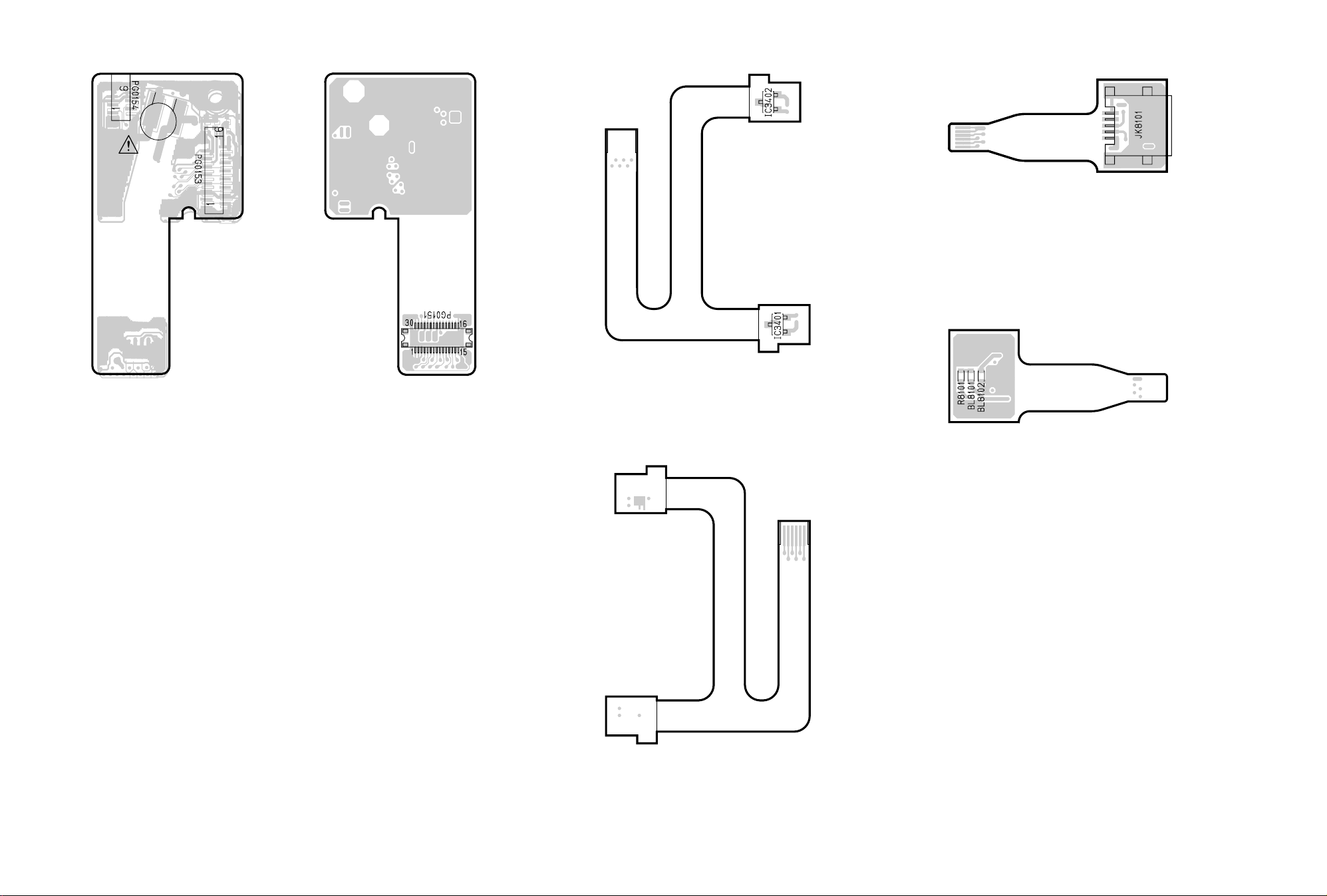
3-5 SHE, MR, USB CIRCUIT BOARD DIAGRAMS
USB -SIDE A-
[PATTERN No.JD1153-5]
CN8101
USB -SIDE A-
[PATTERN No.JD1153-5]
CN8101
BA1801
SHE -SIDE A-
[PATTERN No.JD1153-5]
[PATTERN No.JD1153-5]
SHE -SIDE B-
MR -SIDE B-
[PATTERN No.JD1153-5]
USB -SIDE B-
[PATTERN No.JD1153-5]
CN3401
MR -SIDE A-
[PATTERN No.JD1153-5]
VDR-M30PP/EG/B/EN SHE, MR, USB C.B.A.
Page 68

3-6 AEL CIRCUIT BOARD DIAGRAM
3
12
12
3
E
D
TL7041
C
E
D
C
E
TL3719
D
TL6102
C
TL6101
E
D
C
Q7009
B
A
3
C7004
B
A
12
B
A
12
AEL -SIDE A-
[PATTERN No.JA2090-5]
61 120
60 1
AEL -SIDE B-
[PATTERN No.JA2090-5]
B
A
3
VDR-M30PP/EG/B/EN AEL C.B.A.
Page 69

3-7 LCD CIRCUIT BOARD DIAGRAM
C
B
4
TL3461
TL3418
3
12
TL3462
C
To
BACK
LIGHT
B
CAUTION
RISK OF ELECTRIC SHOCK
A
A
4
3
12
LCD
[PATTERN No.JA2104-4]
VDR-M30PP/EG/B/EN LCD C.B.A.
Page 70

3-8 MAN CIRCUIT BOARD DIAGRAM
TL0513
TL0510
22
(3.1)
TL0516
TL0515
30
(3.1)36(3.1)
TL0503
TL4011
TL0511
(3.4)
TL1544TL0502TL0519TL0520
TL2004 TL0521 TL0501 TL0518 TL1543
33(4.8)
32(4.8)
31(4.8)
30(4.8)
28(2.5)
26(3.1)
25(3.1)
1
1- 5
(8.0)
TL0517 TL1547
F0502
(K:1.5A/32V)
59
(7.8)
(7.8)58(7.8)
17
(4.8)23(4.8)27(7.8)
4
(3.1)
K
F0503
KKK
52
(K:1.5A/32V)
F0501
(K:1.5A/32V)
F0504
(K:1.5A/32V)
TL0512
TL1514
2(-7.9)5(-7.9)
6(-7.0)
38(4.8)
39(4.8)
40(4.8)
41(4.8)
43(2.5)
367035
5(3.1)
TL5002
TL5001
TL1538
(3.1)
14(3.1)
5
9(3.1)
63(7.8)
TL1536
TL1534
TL1531
TL1529
TL1528
TL1526
TL1525
TL1523
TL2521
TL1527 TL1522
TL1541
TL1546
TL1501
3
(7.8)
TL6006
3
(4.7)
TL1524
TL1545
14
(3.1)
5
(3.1)
5
(3.1)
IC2007
27(3.2)
33(3.2)
14
(3.2)
TL2082
TL2093
TL2083
TL2092
TL2084
TL2091
TL2085
TL2090
TL2095
TL2089
TL2086
6
(3.2)
16
(15.0)20(15.0)
(-7.0)
2
TL2088
3
10
(3.2)
(15.0)
14
(-7.0)
3
54
(3.1)
40(3.2)
43(3.2)
43(3.2)
14(2.5)
103(3.1)
17(12.1)
97(5.0)
24(5.0)
119(4.8)
120 61
1 60
2(3.1)
10(3.1)
(3.2)
14
(3.1)
24(3.2)
18(3.2)
17(3.2)
13(3.2)
83(7.7)
82(7.7)
81(3.1)
80(4.8)
79(3.1)
78(3.1)
12
(7.8)
(5.0)
1
5
TL6008
TL6010
(3.1)
11
TL6011
TL1537
TL1535
TL1533
TL1532
TL1530
TL6009
TL6005
6
(3.4)8(3.2)
7
(7.9)
8
(3.2)
MAIN -SIDE A-
[PATTERN No.JA2089-6]
J6002
AV
INPUT/OUTPUT
EXTERNAL MIC
MAIN -SIDE B-
[PATTERN No.JA2089-6]
J6001
VDR-M30PP/EG/B/EN MAN C.B.A.
Page 71

3-9 DRV CIRCUIT BOARD DIAGRAM
(3.2)
8
30
(3.3)
(0.5A)
30(4.6)
31(4.6)
32(4.8)
26(3.2)
28(2.4)
33(4.8)
13 5
25(3.2)
70 36
5
(3.3)
43(2.4)
41(4.7)
40(4.7)
39(4.8)
38(4.8)
11
(4.6)
41
(3.2)
43
(4.6)
47
(4.6)
(4.6)
(4.6)
(4.6)
12
(4.6)
42
46
73
(4.6)
82
(4.7)
57
(3.3)
50
(4.8)
11
23
(4.6)
(4.7)
(4.7)
16
(4.7)
17
32
(4.7)
34
(4.7)
44
(4.7)
(4.5)
64
49
DRV -SIDE A-
[PATTERN No.JA2084-4]
Note: Voltage values are in reading status.
Example: 24 (4.7): Terminal no. (voltage value)
Supplement: Since the DVD drive is intermittently operated, set to the reading status in which
laser light is emitted from the pickup.
8
(3.0)
14
(2.5)
15(3.3)
16(3.3)
(3.3)
5
(3.3)
8
(3.3)
8
(3.3)
8
(3.3)
4
(4.8)
8
(4.8)
4
(4.8)
8
8
(4.8)
11(3.3)
4(4.8)
(4.8)
3(4.8)
8
(3.3)
8
5
(3.3)
(4.8)
5
4
(4.8)
(4.8)
1
(4.8)
16
(4.8)14(4.8)
17
(4.8)
5
(4.8)
1
3
(4.8)
32
(4.8)
DRV -SIDE B-
[PATTERN No.JA2084-4]
VDR-M30PP/EG/B/EN DRV C.B.A.
Page 72

3-10 SID CIRCUIT BOARD DIAGRAM 3-11 HDM CIRCUIT BOARD DIAGRAM
HDM -SIDE A-
23
7
(4.7)
(4.7)
22
(4.7)
(4.8)
1
14
(4.8)
9
(3.3)
8(3.3)
11(3.3)
9
3(4.8)
4(4.8)
(3.3)
SID -SIDE A-
[PATTERN No.JA2084-4]
8(3.3)
SID -SIDE B-
[PATTERN No.JA2084-4]
Note: Voltage values are in reading status.
Example: 24 (4.7): Terminal no. (voltage value)
Supplement: Since the DVD drive is intermittently operated, set to the reading status in which
laser light is emitted from the pickup.
HDM -SIDE B-
17
20
(4.9)
26
25 17
27
(3.1)
19
32
3
(3.1)8(4.9)
(4.9)21(4.925(4.9) )
16
10
5(4.9)
9(4.9)
11(3.1)
41(4.8)
6(4.9)
10(4.9)
40(4.8)
VDR-M30PP/EG/B/EN SID, HDM C.B.A.
Page 73

3-12 IDENTIFICATION OF PARTS LOCATION
LCD AEL
Symbol
Parts
Symbol
No.
Location
C
C3401 3B
C3402 3B
C3403 3B
C3404 3B
C3405 2B
C3406 2B
C3407 3B
C3408 2B
C3409 2C
C3410 3C
C3411 3C
C3412 3B
C3413 3B
C3414 3B
C3415 3A
C3416 3A
C3417 3A
C3418 2A
C3419 3A
C3420 2B
C3451 2A
C3452 1A
C3453 1A
C3455 3A
D
D3401 3A
D3402 3A
IC
IC3401 3B
L
L3401 3B
L3402 2A
L3403 3A
L3441 2A
PG
PG3401 3B
PG3402 2B
PG3403 3A
Q
Q3409 2C
Q3410 3C
Q3411 2A
R
R3407 2B
R3408 3B
R3409 2B
R3410 2B
R3411 2C
R3412 2C
R3413 3C
R3414 3C
R3415 3C
R3419 3A
R3422 2C
R3423 3C
R3427 4A
R3434 3A
Parts
No.
Location
R3435 3A
R3436 3A
R3437 3A
R3479 2A
T
T3401 2A
TL
TL3418 4B
TL3462 1C
Symbol
Parts
No.
Location
BL
BL1301 A-3A
BL1302 B-3A
BL6201 A-2C
BL6202 A-2D
C
C1301 B-2A
C1302 B-3A
C1303 B-3A
C1304 A-3A
C1305 B-3A
C1306 B-3A
C1307 B-3B
C1308 B-3B
C1309 B-3B
C1310 B-2A
C1311 B-3A
C1312 B-3A
C1314 B-3A
C1315 B-3A
C1316 B-3A
C1318 B-2A
C1319 A-3A
C1320 A-3A
C1321 A-3A
C1322 A-3A
C1323 A-3A
C1324 B-2A
C1325 B-3B
C1326 B-3B
C1327 B-3B
C1329 B-3A
C1330 B-3A
C1331 A-3B
C1332 B-3B
C3704 A-1E
C3705 A-1E
C3706 A-3E
C3707 A-3E
C3708 A-3E
C3710 A-2E
C3711 A-2D
C3713 A-2D
C3714 A-2D
C3715 A-2D
C3716 A-2E
C3717 A-2E
C3718 A-2E
C3721 A-1E
C3723 A-1E
C3724 A-1E
C3725 A-2E
C3728 A-2D
C3891 A-2E
C3892 A-3D
C3893 A-3D
C3895 A-3D
C3896 A-3D
Symbol
Parts
No.
Location
C6101 A-2B
C6102 A-2B
C6103 A-2B
C6104 A-2B
C6105 A-2B
C6106 A-2A
C6107 A-2A
C6108 A-2A
C6109 A-2A
C6110 A-2A
C6111 A-2B
C6112 A-2A
C6113 A-2A
C6114 A-2B
C6115 A-2B
C6116 A-2A
C6117 A-2B
C6118 A-2B
C6119 A-2C
C6120 A-2C
C6121 A-2C
C6127 A-2B
C6128 A-2C
C6131 A-2C
C6201 A-2D
C6202 A-2D
C6203 A-2C
C6204 A-2C
C6205 A-2C
C6206 A-2C
C6207 A-2C
C6208 A-2C
C6301 A-1B
C6302 A-1B
C6303 A-1C
C6304 A-1C
C6305 A-1C
C6306 A-1C
C6307 A-1C
C6308 A-1C
C6309 A-1C
C6310 A-1C
C6311 A-1C
C6312 A-1B
C6313 A-1C
C6314 A-1C
C6315 A-1C
C6316 A-1B
C6317 A-1C
C6318 A-1C
C6319 A-1B
C6320 A-1B
C6321 A-1B
C6322 A-1B
C6323 A-1B
C6324 A-1B
C6326 A-1B
C6327 A-1B
Symbol
Parts
No.
Location
C6328 A-1B
C6329 A-1B
C6330 A-1B
C6331 A-1B
C6332 A-1B
C6333 A-1B
C6334 A-1B
C6336 A-2B
C7001 B-1B
C7002 A-1D
C7004 A-2B
C7013 B-1B
C7014 B-1C
D
D3702 A-2D
D6301 A-1C
D7001 A-2B
IC
IC1301 B-3A
IC1302 A-3A
IC1303 A-3A
IC3701 A-2E
IC6101 A-2A
IC6102 A-2C
IC6103 A-1B
IC6201 A-2D
IC7001 A-1D
L
L3704 A-2E
L3891 A-3D
L3892 A-3D
L3893 A-3D
L6102 A-2B
L6103 A-2C
L6301 A-1C
L6302 A-1C
L6303 A-1C
L6304 A-1B
L6305 A-1B
L6306 A-1B
PG
PG1301 A-3A
PG7001 B-2B
PG7002 A-3B
PG7003 B-3A
PG7004 A-2E
PG7008 A-2B
PG7009 A-3C
Q
Q1301 A-3B
Q1302 B-3A
Q1303 A-3B
Q1304 B-2B
Q3891 A-2E
Q3892 A-2E
Q6101 A-2B
Q6102 A-2A
Q6103 A-2B
Symbol
Parts
No.
Location
Q6104 A-2B
Q6105 A-2B
Q6108 A-2B
Q6204 A-2B
Q6207 A-2B
Q6208 A-2B
Q7009 B-1B
R
R1303 B-3A
R1304 B-3A
R1305 B-3A
R1306 B-3B
R1307 B-3B
R1308 B-3B
R1310 B-3B
R1312 B-3B
R1314 B-3B
R1315 B-3A
R1317 B-3A
R1318 B-2A
R1319 A-3A
R1320 A-3A
R1321 A-3A
R1322 A-3A
R1323 A-3B
R1324 A-3A
R1325 A-3A
R1326 A-3A
R1327 A-3A
R1328 A-3B
R1329 A-3B
R1330 A-3B
R1332 B-3A
R1333 A-3A
R1334 A-3A
R1336 B-2A
R1337 A-3B
R1347 B-3B
R1348 B-2A
R1349 B-2A
R1350 B-2A
R3703 A-2E
R3704 A-2E
R3705 A-2E
R3706 A-2E
R3707 A-2D
R3708 A-2D
R3709 A-2D
R3710 A-2E
R3711 A-2D
R3712 A-1E
R3713 A-1E
R3714 A-1E
R3891 A-2E
R3892 A-2D
R6101 A-2B
R6102 A-2B
R6103 A-2B
Symbol
Parts
No.
Location
R6104 A-2B
R6105 A-2B
R6106 A-2B
R6107 A-2B
R6108 A-2B
R6109 A-2B
R6110 A-2A
R6111 A-2A
R6112 A-2A
R6113 A-2A
R6114 A-2A
R6115 A-2A
R6116 A-2A
R6117 A-2B
R6118 A-2B
R6119 A-2A
R6120 A-2A
R6121 A-2B
R6122 A-2B
R6123 A-2B
R6124 A-2B
R6125 A-2B
R6126 A-2B
R6127 A-2A
R6128 A-2A
R6129 A-2A
R6130 A-2B
R6131 A-2B
R6132 A-2B
R6133 A-2B
R6134 A-2C
R6135 A-2C
R6136 A-2C
R6137 A-2C
R6138 A-2C
R6139 A-2C
R6140 A-2C
R6141 A-2C
R6149 A-2B
R6150 A-2B
R6151 A-2B
R6152 A-2B
R6201 A-2C
R6202 A-2C
R6205 A-2C
R6206 A-2C
R6207 A-2C
R6208 A-2C
R6209 A-2D
R6301 A-1B
R6302 A-1C
R6304 A-1C
R6306 A-1C
R6307 A-1C
R6308 A-1C
R6309 A-2B
R6310 A-2C
R6311 A-1B
Symbol
Parts
No.
Location
R6312 A-1B
R6313 A-1B
R6314 A-1B
R6316 A-1B
R6317 A-1B
R6318 A-1B
R6319 A-1B
R6324 A-1B
R6325 A-1B
R6326 A-1B
R6327 A-1B
R6328 A-1B
R6330 A-1B
R7006 A-1A
R7009 A-1A
R7010 A-1A
R7011 A-2B
R7012 A-1A
R7013 A-1A
R7014 A-2B
R7015 A-1A
R7018 A-1A
R7021 A-3C
R7022 A-3C
R7023 A-3B
R7024 A-3C
R7026 A-3C
R7030 B-2A
R7031 B-2A
R7032 A-2E
R7036 A-2E
R7051 A-2B
R7052 A-2B
R7053 A-2B
R7054 A-1A
R7055 A-2B
R7056 A-2B
R7057 A-2B
R7058 A-1A
SW
SW7001 A-1D
TL
TL3719 B-1E
TL6101 B-2C
TL6102 B-2C
VDR-M30PP/EG/B/EN IDENTIFICATIONOF PARTS LOCATION
Page 74

3-12 IDENTIFICATION OF PARTS LOCATION
LCD AEL
Symbol
Parts
Symbol
No.
Location
C
C3401 3B
C3402 3B
C3403 3B
C3404 3B
C3405 2B
C3406 2B
C3407 3B
C3408 2B
C3409 2C
C3410 3C
C3411 3C
C3412 3B
C3413 3B
C3414 3B
C3415 3A
C3416 3A
C3417 3A
C3418 2A
C3419 3A
C3420 2B
C3451 2A
C3452 1A
C3453 1A
C3455 3A
D
D3401 3A
D3402 3A
IC
IC3401 3B
L
L3401 3B
L3402 2A
L3403 3A
L3441 2A
PG
PG3401 3B
PG3402 2B
PG3403 3A
Q
Q3409 2C
Q3410 3C
Q3411 2A
R
R3407 2B
R3408 3B
R3409 2B
R3410 2B
R3411 2C
R3412 2C
R3413 3C
R3414 3C
R3415 3C
R3419 3A
R3422 2C
R3423 3C
R3427 4A
R3434 3A
Parts
No.
Location
R3435 3A
R3436 3A
R3437 3A
R3479 2A
T
T3401 2A
TL
TL3418 4B
TL3462 1C
Symbol
Parts
No.
Location
BL
BL1301 A-3A
BL1302 B-3A
BL6201 A-2C
BL6202 A-2D
C
C1301 B-2A
C1302 B-3A
C1303 B-3A
C1304 A-3A
C1305 B-3A
C1306 B-3A
C1307 B-3B
C1308 B-3B
C1309 B-3B
C1310 B-2A
C1311 B-3A
C1312 B-3A
C1314 B-3A
C1315 B-3A
C1316 B-3A
C1318 B-2A
C1319 A-3A
C1320 A-3A
C1321 A-3A
C1322 A-3A
C1323 A-3A
C1324 B-2A
C1325 B-3B
C1326 B-3B
C1327 B-3B
C1329 B-3A
C1330 B-3A
C1331 A-3B
C1332 B-3B
C3704 A-1E
C3705 A-1E
C3706 A-3E
C3707 A-3E
C3708 A-3E
C3710 A-2E
C3711 A-2D
C3713 A-2D
C3714 A-2D
C3715 A-2D
C3716 A-2E
C3717 A-2E
C3718 A-2E
C3721 A-1E
C3723 A-1E
C3724 A-1E
C3725 A-2E
C3728 A-2D
C3891 A-2E
C3892 A-3D
C3893 A-3D
C3895 A-3D
C3896 A-3D
Symbol
Parts
No.
Location
C6101 A-2B
C6102 A-2B
C6103 A-2B
C6104 A-2B
C6105 A-2B
C6106 A-2A
C6107 A-2A
C6108 A-2A
C6109 A-2A
C6110 A-2A
C6111 A-2B
C6112 A-2A
C6113 A-2A
C6114 A-2B
C6115 A-2B
C6116 A-2A
C6117 A-2B
C6118 A-2B
C6119 A-2C
C6120 A-2C
C6121 A-2C
C6127 A-2B
C6128 A-2C
C6131 A-2C
C6201 A-2D
C6202 A-2D
C6203 A-2C
C6204 A-2C
C6205 A-2C
C6206 A-2C
C6207 A-2C
C6208 A-2C
C6301 A-1B
C6302 A-1B
C6303 A-1C
C6304 A-1C
C6305 A-1C
C6306 A-1C
C6307 A-1C
C6308 A-1C
C6309 A-1C
C6310 A-1C
C6311 A-1C
C6312 A-1B
C6313 A-1C
C6314 A-1C
C6315 A-1C
C6316 A-1B
C6317 A-1C
C6318 A-1C
C6319 A-1B
C6320 A-1B
C6321 A-1B
C6322 A-1B
C6323 A-1B
C6324 A-1B
C6326 A-1B
C6327 A-1B
Symbol
Parts
No.
Location
C6328 A-1B
C6329 A-1B
C6330 A-1B
C6331 A-1B
C6332 A-1B
C6333 A-1B
C6334 A-1B
C6336 A-2B
C7001 B-1B
C7002 A-1D
C7004 A-2B
C7013 B-1B
C7014 B-1C
D
D3702 A-2D
D6301 A-1C
D7001 A-2B
IC
IC1301 B-3A
IC1302 A-3A
IC1303 A-3A
IC3701 A-2E
IC6101 A-2A
IC6102 A-2C
IC6103 A-1B
IC6201 A-2D
IC7001 A-1D
L
L3704 A-2E
L3891 A-3D
L3892 A-3D
L3893 A-3D
L6102 A-2B
L6103 A-2C
L6301 A-1C
L6302 A-1C
L6303 A-1C
L6304 A-1B
L6305 A-1B
L6306 A-1B
PG
PG1301 A-3A
PG7001 B-2B
PG7002 A-3B
PG7003 B-3A
PG7004 A-2E
PG7008 A-2B
PG7009 A-3C
Q
Q1301 A-3B
Q1302 B-3A
Q1303 A-3B
Q1304 B-2B
Q3891 A-2E
Q3892 A-2E
Q6101 A-2B
Q6102 A-2A
Q6103 A-2B
Symbol
Parts
No.
Location
Q6104 A-2B
Q6105 A-2B
Q6108 A-2B
Q6204 A-2B
Q6207 A-2B
Q6208 A-2B
Q7009 B-1B
R
R1303 B-3A
R1304 B-3A
R1305 B-3A
R1306 B-3B
R1307 B-3B
R1308 B-3B
R1310 B-3B
R1312 B-3B
R1314 B-3B
R1315 B-3A
R1317 B-3A
R1318 B-2A
R1319 A-3A
R1320 A-3A
R1321 A-3A
R1322 A-3A
R1323 A-3B
R1324 A-3A
R1325 A-3A
R1326 A-3A
R1327 A-3A
R1328 A-3B
R1329 A-3B
R1330 A-3B
R1332 B-3A
R1333 A-3A
R1334 A-3A
R1336 B-2A
R1337 A-3B
R1347 B-3B
R1348 B-2A
R1349 B-2A
R1350 B-2A
R3703 A-2E
R3704 A-2E
R3705 A-2E
R3706 A-2E
R3707 A-2D
R3708 A-2D
R3709 A-2D
R3710 A-2E
R3711 A-2D
R3712 A-1E
R3713 A-1E
R3714 A-1E
R3891 A-2E
R3892 A-2D
R6101 A-2B
R6102 A-2B
R6103 A-2B
Symbol
Parts
No.
Location
R6104 A-2B
R6105 A-2B
R6106 A-2B
R6107 A-2B
R6108 A-2B
R6109 A-2B
R6110 A-2A
R6111 A-2A
R6112 A-2A
R6113 A-2A
R6114 A-2A
R6115 A-2A
R6116 A-2A
R6117 A-2B
R6118 A-2B
R6119 A-2A
R6120 A-2A
R6121 A-2B
R6122 A-2B
R6123 A-2B
R6124 A-2B
R6125 A-2B
R6126 A-2B
R6127 A-2A
R6128 A-2A
R6129 A-2A
R6130 A-2B
R6131 A-2B
R6132 A-2B
R6133 A-2B
R6134 A-2C
R6135 A-2C
R6136 A-2C
R6137 A-2C
R6138 A-2C
R6139 A-2C
R6140 A-2C
R6141 A-2C
R6149 A-2B
R6150 A-2B
R6151 A-2B
R6152 A-2B
R6201 A-2C
R6202 A-2C
R6205 A-2C
R6206 A-2C
R6207 A-2C
R6208 A-2C
R6209 A-2D
R6301 A-1B
R6302 A-1C
R6304 A-1C
R6306 A-1C
R6307 A-1C
R6308 A-1C
R6309 A-2B
R6310 A-2C
R6311 A-1B
Symbol
Parts
No.
Location
R6312 A-1B
R6313 A-1B
R6314 A-1B
R6316 A-1B
R6317 A-1B
R6318 A-1B
R6319 A-1B
R6324 A-1B
R6325 A-1B
R6326 A-1B
R6327 A-1B
R6328 A-1B
R6330 A-1B
R7006 A-1A
R7009 A-1A
R7010 A-1A
R7011 A-2B
R7012 A-1A
R7013 A-1A
R7014 A-2B
R7015 A-1A
R7018 A-1A
R7021 A-3C
R7022 A-3C
R7023 A-3B
R7024 A-3C
R7026 A-3C
R7030 B-2A
R7031 B-2A
R7032 A-2E
R7036 A-2E
R7051 A-2B
R7052 A-2B
R7053 A-2B
R7054 A-1A
R7055 A-2B
R7056 A-2B
R7057 A-2B
R7058 A-1A
SW
SW7001 A-1D
TL
TL3719 B-1E
TL6101 B-2C
TL6102 B-2C
VDR-M30PP/EG/B/EN IDENTIFICATIONOF PARTS LOCATION
Page 75

8
7
A/V
MIC
(Inside the cover)
12 34 5 6
11
910
BATTERY EJECT
(Bottom)
1 Recording indicator
The red indicator will light during recording.
2 Optical 10 zoom lens
3 Lens hood
Always remove this lens hood when using
generally available tele-conversion or wideconversion lens.
4 Infrared receiver
When the remote control is used to operate the
DVD video camera/recorder, this receiver will
receive the infrared signal.
5 Zoom lever
Push the lever to the T side for telephoto, or to
the W side for wide-angle.
6 Accessory shoe
Accessories, such as a stereo microphone
(VW-VMS2E; optional), are attached here.
7 External microphone jack
8 AV output jack (EG)
AV input/output jack (PP)
9 Stereo microphone
10 2.5” type liquid crystal display (inside)
11 BATTERY EJECT switch
The BATTERY EJECT switch is located on the
bottom of this DVD video camera/recorder:
Slide it when removing the battery.
Page 76

12 13 14 1715
16
18 19 21 2322
12 Viewfinder
13 Dioptre control
To adjust the focus of image appearing in the
viewfinder. (Pull out the viewfinder.)
14 ACCESS/PC indicator
Will blink or light while the DVD video camera/
recorder is operating.
15 DISC EJECT button
Press down and release this button to open the
disc gui de.
16 CARD ACCESS indicator
20
17 Card insertion block
18 Battery attachment platform
19 Record button (REC)
20 Shoulder strap holders (EG)
Shoulder belt attachment portion (PP)
21 Power switch
22 Speaker
23 Hand strap (EG)
Grip belt (PP)
Page 77

24 25 26 27 28 29 30
3632 33 34 3531
24 FULL AUTO button
To switch the DVD video camera/recorder to full
automatic
25 FOCUS butto n
To switch between manual focus and autofocus.
26 EXPOSURE button
Press this button to adjust the exposure.
27 BACK LIGHT (backlight compensation)
button
Press this button when subject is being lighted
from rear.
28 DISC NAVIGATION button
29 SELECT butt on
30 MENU butto n
Press this button to display the menu for setting
camera functions and Disc Navigation.
The camera menu will appear even if disc is not
loaded.
31 Screen display button (DISPLAY)
Press this button to display the details of image
being played back or camera setting status, or
switch the display off.
32 Volume control buttons (VOL)/ buttons
To adjust the volume of sound from speaker,
etc.
33 RESET button
To reset all settings to defaults (status when the
DVD video camera/recorder was shipped from
the factory).
34 USB terminal
35 Joystick
Move the joystick to select a scene or menu
item; then play back the scene or pause it.
36 Stop/cancel button
To end playback or cancel setting of menu.
Page 78

37
38
39
43
44
40
41
42
37 REC button
38 DIGITAL ZOOM button
39 Reverse skip button
40 Reverse search button
41 DISC NAVIGATION button
42 MENU butto n
43 ZOOM T button
45
46
47
48
49
50
51
45 Forward search button
46 Play/pause button
47 Forward skip button
48 DISPLAY button
49 Stop button
50 DELETE button
51 SELECT button
44 ZOOM W button
* The buttons on remote control will function the same as those on DVD video camera/recorder.
Page 79

2. SCHEMATIC DIAGRAMS
2-1 FRT SCHEMATIC DIAGRAM
G
To
MIC
F
To
FAF
CN1801
CODE PART NAME
LE 2SC5385T11
1ZS 2SD2345-S
64 DTC114YE
MO MA132WA
ONE VOLTAGE:PB OR REC MODE
*
TWO VOLTAGES:PB AND (REC) MODE
4321 8765
2-2 FAF SCHEMATIC DIAGRAM
G
F
To
FRT
PG1801
E
2.5 4.7
3.6
(0)
D
0(3)
0
IR
RECEIVER
0
0
2-3 SAF SCHEMATIC DIAGRAM
FAF
C
4.7
0
4.7
00
0
To
BOARD To BOARD
[AEL]
PG7003
E
D
C
To
L CASE
(OPERATION SW)
B
INFRARED RAYS
OPTICAL
FRT
PG8012
SAF
A
VDR-M30PP/EG/B/EN FRT, FAF, SAF SCHEMATIC DIAGRAM
4321
To
BOARD To BOARD
PG7004
B
A
8765
Page 80

4321 8765
SHE
To
BOARD To BOARD
[AEL]
PG7009
To
EVF
UNIT
To
GYR
CN1401
VL1220/F3A
SHE
To
BOARD To BOARD
[AEL]
PG7009
To
EVF
UNIT
To
GYR
CN1401
VL1220/F3A
2-4 GYR SCHEMATIC DIAGRAM 2-5 SHE SCHEMATIC DIAGRAM
G
1.3
0
F
1.3
0
E
D
1.4
CODE PART NAME
3.1
1.2
3.1
5H XP4501
ONE VOLTAGE: PB OR REC MODE.
*
TWO VOLTAGES: PB AND (REC) MODE.
1
2
3
4
5
6
To
SHE
PG0154
G
F
E
D
0-3.1
C
VCC
DET
0-3.1
B
1.3 1.3
1.3
1.33.1
C
B
GND
1.31.3
0
1.3 1.3
0
0
GYR
A
VDR-M30PP/EG/B/EN GYR, SHE SCHEMATIC DIAGRAM
4321
8765
A
Page 81
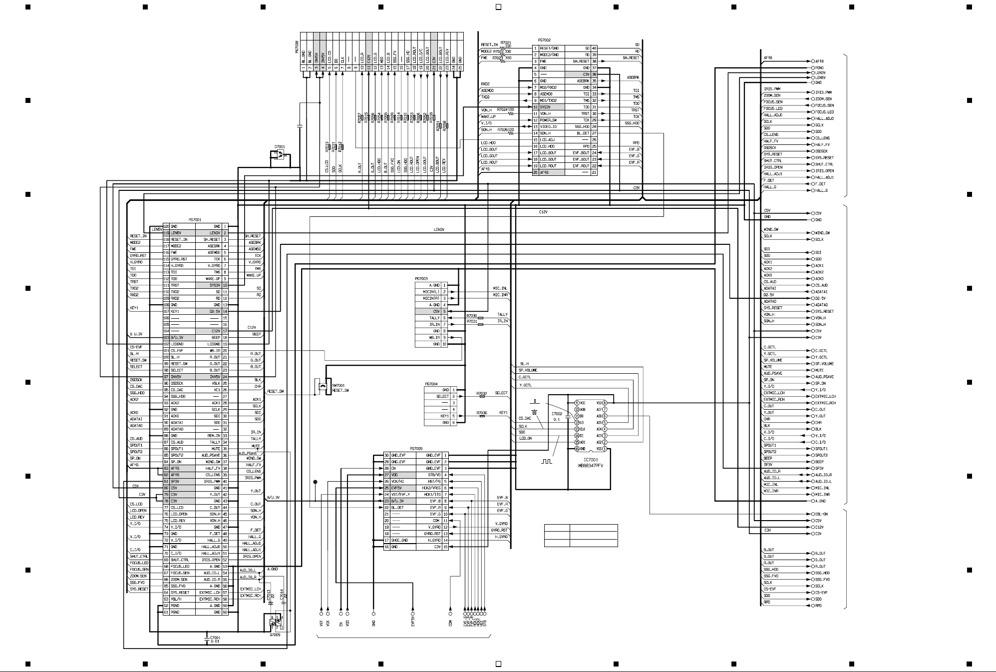
2-6 BOARD To BOARD [AEL] SCHEMATIC DIAGRAM
25242322212019181716151413121110987654321
G
0.1
C7004
F
E
D
C
B
A
To
MAN
PG1501
MP
TL7041
0
0
0
0
0
0
H9
1B
BM10696R
BM10696R
2B
BM10696R
3B
4B
To
LCD
PG3401
BM10349R
BM10696R
BM10696R
BM10696R
5B
BM10696R
BM10696R
To
FAF
CN7003
To
EVF
1B-14B
BM10696R
BM10696R
To
SAF
CN7004
To
SHE
PG0151
4321 8765
BM10696R
BM10696R
BM10349R
BM10696R
BM10696R
BM10696R
BM10696R
BM10696R
BM10696R
BM10696R
6B
7B8B9B
10B
11B
12B
13B
14B
4321
FOR ADJUSTMENT.
3.1
3.1
0
3.1
0
ONE VOLTAGE:PB OR REC MODE
*
TWO VOLTAGES:PB AND (REC) MODE
-
-
3.1
0
3.1
0
CODE PART NAME
H9 UMH9N
MP MA133
DECODER
3.1
0
1.7
1.6
3.1(0)
3.1
0
BOARD To BORAD [AEL]
1A
2A
3A
4A
5A
6A
7A
8A
To
9A
LENS DRIVE
10A
1A-21A
11A
12A
13A
14A
15A
16A
17A
18A
19A
20A
21A
18C
19C
20C
21C
23C
24C
25C
26C
27C
22C
29C
30C
28C
31C
32C
33C
34C
36C
To
AUDIO
37C
1C-42C
38C
39C
40C
41C
42C
10C
4C
5C
6C
7C
9C
8C
11C
12C
13C
14C
15C
35C
16C
17C
1C
2C
3C
15B
16B
17B
18B
To
19B
EVF
20B
15B-27B
21B
22B
23B
24B
25B
26B
27B
VDR-M30PP/EG/B/EN BOARD TO BOARD [AEL] SCHEMATIC DIAGRAM
8765
G
F
E
D
C
B
A
Page 82

2-7 LENS DRIVE [AEL] SCHEMATIC DIAGRAM
4321 8765
G
1A
3A
AE
F
3.0
0
(0)
(-)
0
64
To
LENS
E
UNIT
D
8.4 6.2
7.6
0.4(1.9)
3.1
8.0
1.6
1.6
PB: 0
(
REC:
1.6
2.2
1.5
1.5
7.6
REG
CONT.
6.2
6.2
+B
0
0
GND
3V
+B
C
0
BM10685R
(-)0(-)
3.2
FR
1.2
3.0
0
1.1
(2)1.6
PB: 0
(
REC:
HALL
AMP
IRIS MOTOR
DRIVE
IRIS
LOGIC
AF/ZOOM
IRIS DRIVE
1.5 1.5 1.5 0 0
0
(-)
0.21.01.21.6
0.3
0
ZOOM MOTOR
DRIVE
FOCUS MOTOR
DRIVE
GND
RESET5V VCC
4.7 3.1 3.2
PB: 0
(
REC:
PB: 0
(
REC:
DECORDER
3.1
0.2
PB: 0
(
0.3
REC:
0
----
+B
0.3
0
EXT2
0.3
0
GND
3.2
0
PB: 0.2
(
0.4
REC:
0
6.2
-
-
-
-
0
-
3.2
0
(
PB: 0
REC:
3.0
0
IRIS DET
PB: 0
(
REC:
(1.4)
2.3
(1.5)
1.5
0
0
IRIS DET
A
GND
4.8
V+
B
1.8
2.6
(1.6)
1.8
0
(-)
0
(-)
0
64
CODE PART NAME
AE 2SB1424
FR 2SA1774RS
64 DTC114YE
ONE VOLTAGE:PB OR REC MODE
*
TWO VOLTAGES:PB AND (REC) MODE
0(-)
2.3(1.5)
(1.4)
4.8
0
0
B
A
PB: 3.2
(
3.2
0
REC:
3.2
0
To
BOARD To BOARD
1A-21A
LENS DRIVE [AEL]
VDR-M30PP/EG/B/EN LENS DRIVE [AEL] SCHEMATIC DIAGRAM
4321
5A
6A
7A
8A
9A
10A
2A
11A
12A
13A
14A
15A
16A
4A
17A
18A
19A
20A
21A
8765
G
F
E
D
C
B
A
Page 83

2-8 AUDIO [AEL] SCHEMATIC DIAGRAM
G
2.32.32.32.32.32.3
4.6
F
E
D
1C
2C
3C
To
BOARD To BOARD
1C-3C
ONE VOLTAGE:PB OR REC MODE
TWO VOLTAGES:PB AND (REC) MODE
CODE PART NAME
FR 2SA1774RS
YR 2SD2216
25 DTC124EE
64 DTC114YE
MI MA132K
*
MIC AMP
2.3 02.32.3 2.32.32.3
4321 8765
YR
3.9 4.6
4.6
3.9
2.2
YR
1.7
1k
0
0
25
3.9
2.2
YR
1.7
1k
0
0
0
25
4C
5C
3.9
2.5
YR
1.9
2.02.02.0
0
GND
0
3.9
2.5
YR
1.9
2.5
1.9
FR
FR
0
A
B
V+
MIC AMP
2.0 3.92.02.0
2.5
1.9
0
TL6102
3.1
PB:
0
(
REC: 0
3.1
0
2.6
0.3
3.1
0
3.1
0
VF
A/D & D/A CONV.
1.4 1.4 1.4 1.4 1.4 1.4 1.4 1.4 1.4
TL6101
--
BE10391R
R6209
-
2.5
3.1
0
2.5
0
3.1
3.1
0
10
BE10391R
SP3V
18C
19C
20C
21C
22C
23C
24C
25C
26C
27C
28C
29C
30C
31C
32C
33C
34C
35C
36C
G
F
E
D
6C
7C
8C
9C
C
To
BOARD To BOARD
4C-17C
B
A
10C
12C
13C
11C
14C
15C
16C
17C
C6330
33
L6305
3.7
V.OUT.Return
3.7
V.OUT
4.8
VCCH[Y/V]
0
2.2
4.8
-
3.1(0)
1.5
1.5
1.6
47
1.5
2.8
1.65
0
GND[SP]
1.6
SP.OUT[-]
GND[Y/V]
Y.OUT.Return
Y.OUT
VIDEO/AUDIO
AMP
SP.P.SAV
VCCH[AUD]
3.2
4.8 2.4 2.3 2.3000
(0)
L.OUT.P.SAV
H.OUT.P.SAV
-------
1.0
(0.5)
3.11.61.10.50000.20.1000 1.21.2
-
MIN MAX
0-3.1
(0)
L.OUT[R]
L.MUTE[R]
GND[LINE]
0
AUDIO [AEL]
(M2)
4.8
0
4.8
0
0
1.5
1.5
1.5
3.1
4.6
0
0
0
0
To
BOARD To BOARD
18C-42C
VDR-M30PP/EG/B/EN AUDIO [AEL] SCHEMATIC DIAGRAM
4321
37C
38C
39C
40C
41C
42C
C
B
A
8765
Page 84

2-9 EVF [AEL] SCHEMATIC DIAGRAM
4321 8765
G
F
E
D
C
B
To
BOARD T o BOARD
15B-27B
15B
16B
17B
18B
19B
20B
21B
22B
23B
24B
25B
26B
27B
0.5
0
0.5
0
0.5
0
CODE PART NAME
FR 2SA1774RS
64 DTC114YE
2 HVU200A-T
ONE VOLTAGE: PB OR REC MODE.
*
TWO VOLTAGES: PB AND (REC) MODE.
3.2
0
0
0
0
0
3.1
3.2
3.2
0.2
00
3.2
0
3.2
0
3.2
0
3.2
0
3.2
-
EVF DRIVER
3.0
0
-
1.8-
G
FR
4.8
4.7
4.2
F
0
12.0
--
-
6.4------
0---00
11.0
0
3.0
0
3.0
0
3.2
0
3.0
0
3.2
0
--
3.0
0
12.0
1.9
1.9
1.9
6.6
0
-
-
-
0
3.1
3.1
0
0.7
-
3.0
0
TL3719
3.2
(2)
3.1
64
0
E
5B
1B
2B
14B
3B
4B
13B
12B
11B
10B
9B
8B
7B
6B
To
BOARD T o BOARD
1B-14B
D
C
TYPE PP TYPE EG
R3707
R3708
100k
100k
39k
150k
B
EVF [AEL]
A
A
VDR-M30PP/EG/B/EN EVF [AEL] SCHEMATIC DIAGRAM
4321
8765
Page 85

2-10 LCD SCHEMATIC DIAGRAM
G
4321 8765
INVERTER
0.7
0
0
0.7
0
15.0
0
15.0
0
TRANS
CAUTION
RISK OF ELECTRIC SHOCK
To
BACK
LIGHT
CODE PART NAME
FR 2SA1774RS
64 DTC114YE
ONE VOLTAGE: PB OR REC MODE.
*
TWO VOLTAGES: PB AND (REC) MODE.
G
F
1
2
3
E
4
5
6
7
8
9
10
11
12
D
13
14
15
16
17
18
19
20
21
C
22
23
24
25
To
BOARD To BOARD
PG7008
To
MR
CN3401
F
12.0 12.0
LCD DRIVER
0.4
0
0.4
0
9.0
3.0
3.0
0
3.0
0
3.0
0
05.83.13.23.2 -
0
3.0
0
3.0
0
0
3.0
0
3.0
0
3.5
0
3.0
0
3.0
0
3.0
0
0
3.1
0
0
3.0
0
3.1
3.1
3.0
0
3.0
0
11.3
FR
0
3.0
64
0
E
D
C
12.0
9.0
3.0
3.1
6.0
-
0
0
0
3.1
0.1 1.5 1.3 2.1 3.1
3.0
0
9.0
3.0
0.4
0
B
To
LCD UNIT
A
LCD
4321
VDR-M30PP/EG/B/EN LCD SCHEMATIC DIAGRAM
8765
B
A
Page 86

2-10 LCD SCHEMATIC DIAGRAM
G
4321 8765
INVERTER
0.7
0
0
0.7
0
15.0
0
15.0
0
TRANS
CAUTION
RISK OF ELECTRIC SHOCK
To
BACK
LIGHT
CODE PART NAME
FR 2SA1774RS
64 DTC114YE
ONE VOLTAGE: PB OR REC MODE.
*
TWO VOLTAGES: PB AND (REC) MODE.
G
F
1
2
3
E
4
5
6
7
8
9
10
11
12
D
13
14
15
16
17
18
19
20
21
C
22
23
24
25
To
BOARD To BOARD
PG7008
To
MR
CN3401
F
12.0 12.0
LCD DRIVER
0.4
0
0.4
0
9.0
3.0
3.0
0
3.0
0
3.0
0
05.83.13.23.2 -
0
3.0
0
3.0
0
0
3.0
0
3.0
0
3.5
0
3.0
0
3.0
0
3.0
0
0
3.1
0
0
3.0
0
3.1
3.1
3.0
0
3.0
0
11.3
FR
0
3.0
64
0
E
D
C
12.0
9.0
3.0
3.1
6.0
-
0
0
0
3.1
0.1 1.5 1.3 2.1 3.1
3.0
0
9.0
3.0
0.4
0
B
To
LCD UNIT
A
LCD
4321
VDR-M30PP/EG/B/EN LCD SCHEMATIC DIAGRAM
8765
B
A
Page 87

4321 8765
2-11 MR SCHEMATIC DIAGRAM 2-13 DRF SCHEMATIC DIAGRAM
G
VOLTAGE:READ AND (WRITE) MODE.
*
REVERSE
SW
AN48800A
3.0
0
0
CN3401
F
AN48800A
3.0
3.0
0
OPEN/CLOSE
SW
To
LCD
PG3403
E
G
F
E
MR
D
D
2-12 USB SCHEMATIC DIAGRAM
2.2k
C
BL8102
PC TERMINAL
B
A
USB
To
MAN
PG5001
To
MAN
PG2002
To
DISC DRIVE UNIT
(DRV-PG9701)
C
B
DRF
A
VDR-M30PP/EG/B/EN MR, USB, DRF SCHEMATIC DIAGRAM
4321
8765
Page 88

1. WIRING DIAGRAM
4321 8765
F
DISC DRIVE UNIT
4PIN
SLID
PG9403
6PIN
PG9303
PG9501
TEST
LENS UNIT
CCD/FOCUS MOTOR/
()
ZOOM MOTOR/IRIS
70PIN
PG2302
DRF
F
MOTOR
PG9701
SID
SPINDLE
E
MOTOR
DISC DRIVE
15PIN
PG9401
PG9404
51PIN
PG9103
DRV
PG2001
PG9301
UNIT
20PIN
TYPE PP:
D
HDM
LOCK
UNIT
PG9404
51PIN
AV INPUT/OUTPUT
TYPE EG:
AV OUTPUT
EXTERNAL
MIC
J6002
J6001
16PIN
PG1501
MAN
PG5001
PG1502
21PIN
CN8061
6PIN
PG2301
PG2002
PG0501
PG1503
6PIN
70PIN
12PIN
8PIN
CN8051
CN8101
BATTERY
TERMINAL
E
REAR COVER
ZOOM SW/
REC SW/
()
EJECT SW
D
USB
JK8101
PC
TERMINAL
PG1801
C
FRT
CN1801
FAF
CN7003
PG0154
PG0153
CN1401
GYR
MIC
5PIN
PG1802
10PIN
10PIN
SHE
16PIN
DISC
COVER
POWER SW/
SPEAKER/
()
CARD SOLT
CARD
SD MEMORY
CARD/MMC
C
EVF
MR
18PIN
B
PG3401
A
PG3403
CN3401
6PIN
24PIN
PG3402
25PIN
LCD
LCD
UNIT
BACK
LIGHT
PG1301
PG7003
PG7002
FOR
ADJUSTMENT
25PIN
PG7008
120PIN
PG7001
PG0151
30PIN
PG7009
AEL
(144)
PG7004
6PIN
SAF
CN7004
4321
16PIN
UNIT.
CN8012
6PIN
PG8012
L CASE
(OPERATION SW)
VDR-M30PP/EG/B/EN WIRING DIAGRAM
8765
B
A
 Loading...