

Panasonic TYTP60P30K, TY-TP42P30K, TY-TP65P30K, TY-TP50P30K User Manual
Operating Instructions
Touch Panel
Model No.
TY-TP42P30K
TY-TP50P30K
TY-TP60P30K
TY-TP65P30K
Before connecting, operating or adjusting this product, please read these instructions completely.
Please keep this manual for future reference.
English

Contents
Ŷ
Precautions with regard to setting up ........................2
Ŷ
Maintenance .............................................................3
Ŷ
Components .............................................................4
Ŷ
Touch Panel Assembly ..............................................5
Ŷ
Mounting Touch Panel ...............................................6
Ŷ
Connection with Computer ........................................8
Ŷ
Operating Conditions .................................................8
Ŷ
Touch Operation ........................................................9
Ŷ
Before Calling for Service ........................................10
Ŷ
Speci¿ cations ..........................................................13
Ŷ
External Dimensions ...............................................14
Ŷ
Drawing of Screw Holes ..........................................14
Precautions with regard to setting up
WARNING
Only a quali¿ed technician should perform installation.
• Incorrect installation may cause an accidental fall of the equipment resulting in personal injury.
Do not disassemble or modify the equipment.
• Doing so may cause a ¿ re or electric shock.
Stop using the equipment if anything abnormal occurs.
• Using the equipment even when it is generating smoke or an odor or in other abnormal conditions may cause a ¿ re or other
accidents.
• Stop using it immediately and contact your dealer for repair. Do not repair it by yourself because doing so can be dangerous.
Do not place nearby a container with water or such other liquid in it.
• If water or other liquid is spilled on or gets inside the equipment, a ¿ re or electric shock may occur. (E.g., À ower vases, À ower
pots, glass, and bottles containing cosmetic liquid, chemical liquid or water)
Prevent the equipment from getting wet.
• Doing so may cause a ¿ re or electric shock.
Do not allow foreign materials to get in the equipment.
• Do not insert or let metal objects or combustible materials in the equipment because that may cause a ¿ re or electric shock.
“Pay special attention to children’s behavior.”
CAUTION
Do not use the equipment with any other device than the main device speci¿ ed in the catalog.
• Otherwise the unit may be dropped and become damaged, and personal injury may result.
Installation should be performed only in the speci¿ ed procedure.
• Incorrect installation may cause an accidental fall of the equipment resulting in personal injury.
Do not place the equipment in a humid or dusty location or in a location where the equipment may be exposed to oil
smoke or steam.
• Doing so may cause a ¿ re or electric shock.
Use only the special components for installation.
• Otherwise the main device may fall and get damaged resulting in personal injury.
Two or more people are required to install or remove the main device.
• Otherwise the main device may fall causing personal injury.
Tighten all the screws securely when assembling the equipment.
• Improper assembly may cause an accidental fall or damage of the equipment resulting in personal injury.
Unplug the connecting cable before moving the equipment.
• Failure to do so may cause an accidental fall or turnover resulting in personal injury.
Note for an installation technician
Ŷ
Please hand over these operating instructions to the customer after installation.
Ŷ
Panasonic shall not be accountable for any accident or damage caused by incorrect installation or mishandling.
2

Maintenance
Setup location
Places where the touch panel should not be setup include:
• Locations exposed to direct sunlight, and locations near powerful light sources
(The equipment is an optical touch panel utilizing infrared rays and may function incorrectly when adversely affected.)
• Dusty or humid locations
• Locations that may be exposed to impact or vibration
• Locations near emissions of chemicals or steam, or locations where contact may be made with chemicals
• Locations near sources of electrical noise (generators, air conditioners etc.)
Cautions when in use
Do not touch the infrared transmissive area and screen until the OS starts up after
the computer is turned on.
• Such an action will be detected as defective elements resulting in malfunction of the
equipment. Should this occur, restart the computer. Also when disconnecting and
connecting the USB cable, do not touch the infrared transmissive area and screen.
When using other devices utilizing infrared rays, keep them away from the
equipment to prevent erroneous operation.
Use only the touch pen included with this equipment. Operation is not guaranteed
with other products.
When using the touch panel, be careful not to apply an excessive load to it by
pressing the touch panel body or in any other way.
Cautions when moving
Keep the equipment away from any impact when moving. Failure to do so may result in failure.
Hold the main device when moving.
• Gripping this equipment to move may result in failure.
Do not hold the USB cable when moving.
• Doing so may damage the USB cable resulting in a failure.
Maintenance
Infrared
transmissive
area
* Be sure to unplug the USB cable before cleaning the equipment.
Use a soft cloth and lightly wipe off dirt on the surface of the equipment.
• If soiling is severe, wet a cloth in neutral detergent diluted by 100 times with water, wring well, wipe off the soiled part, and
then wipe well with a dry cloth.
• If liquid droplets get inside, the equipment as well as the screen of the main device may fail. Also do not rub up the screen
with strong force.
Use a soft cloth and wipe off dirt on the surface of the infrared transmissive area.
• Once a day, use a soft cloth to wipe off any soiling or debris on the infrared transmissive area. Failure to do so will cause a
malfunction, but on such an occurrence you can restore normal function simply by gently wiping the soiling off.
• If soiling is severe, wet a cloth in neutral detergent diluted by 100 times of water, wring well, wipe off the soiled part, and then
wipe well with a dry cloth.
Do not directly spray or apply detergent.
• If liquid droplets get inside, the equipment may fail.
Do not apply volatile materials such as insecticides, benzene or thinner.
• The panel may get deteriorated or the coating may come off.
Do not keep the equipment contacted with rubber or plastic materials for a long time.
• The cabinet may get deteriorated.
• When using a chemical wipe, follow the instructions supplied with it.
Cleaning of the inside should be performed at least once a year. Consult your dealer for cleaning.
• If dust builds up inside, the level of infrared light available for touch detection will decrease and may result in poor operation.
Consult your dealer for cleaning of the inside at least once a year.
3
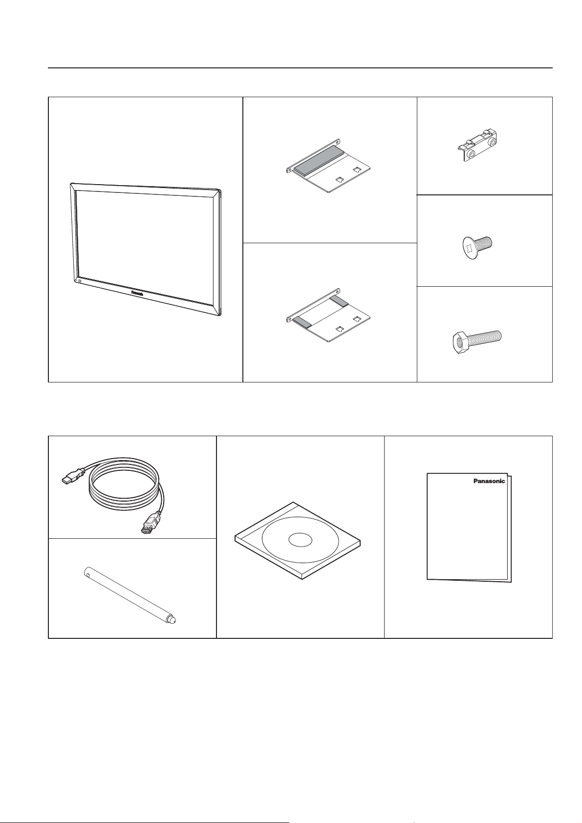
Components
(Check the components and their quantities.)
Touch panel (1)
Mounting bracket A
(for top side) (2)
Mounting bracket A
(for bottom side) (2)
Mounting bracket B (4)
Mounting screw A (8)
Mounting screw B (8)
Accessories
USB extension cable (1) CD-ROM (1)
•
Operating Instructions
•
Driver software
Touch pen (2)
Ŷ
Illustrations are conceptual views and may differ in shape from the actual equipment.
Ŷ
The specifications of the product are subject to change without notice.
•
Windows is a registered trademark of Microsoft Corporation in the USA and other countries.
(The official name of Windows is Microsoft
•
The names of other companies and products appearing in this publication are the trademarks,
registered trademarks or products names of their respective owners.
®
Windows® Operating System.)
Operating Instructions
(1)
4
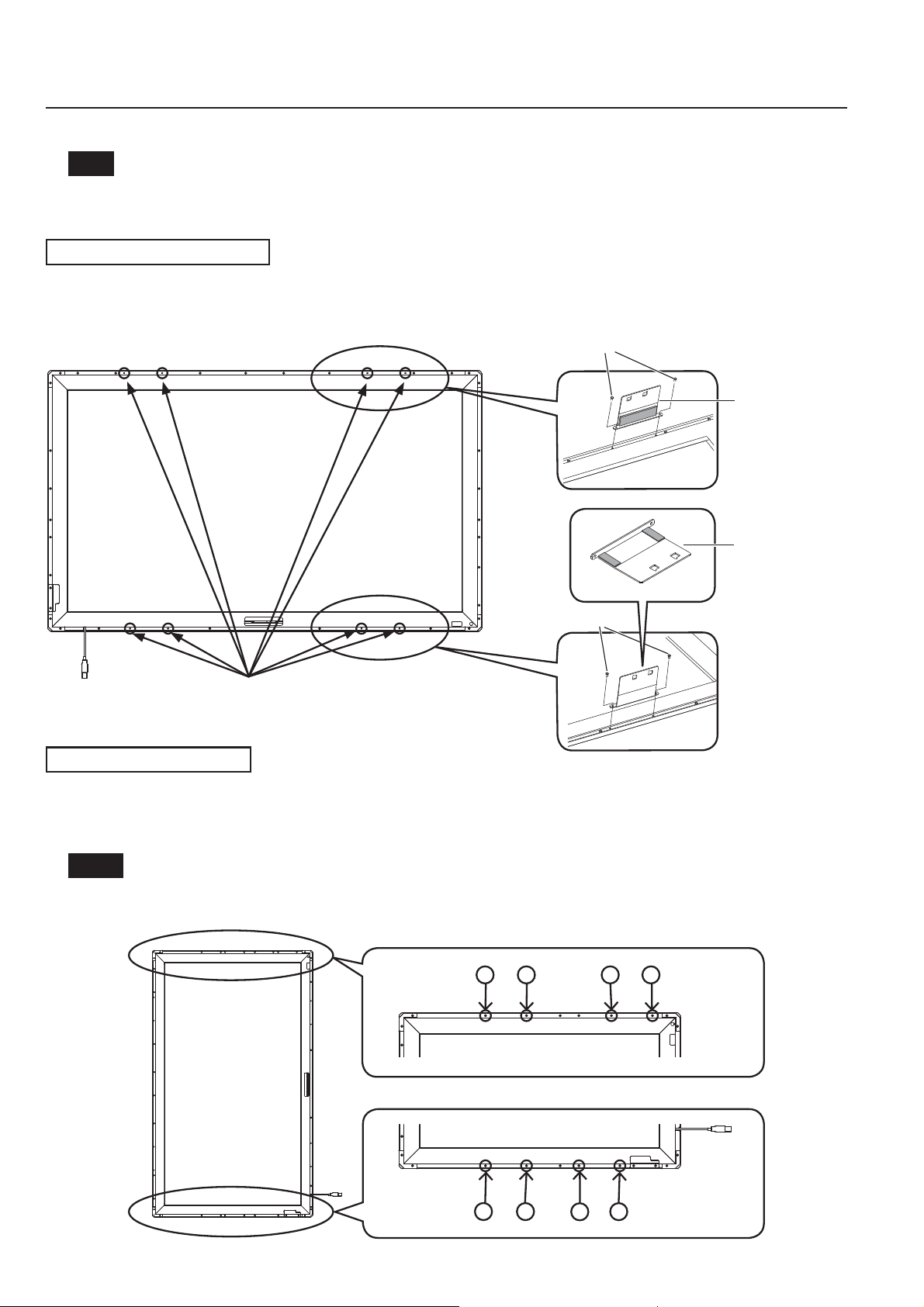
Touch Panel Assembly
Note
•
Place the touch panel making its front surface face down on a clean cloth or blanket to prevent the front
surface of the touch panel from getting scratched or dirty during work.
Mounting in horizontal posture
Attach the mounting brackets A (for top and bottom sides) to the touch panel with the mounting screws A (2 each).
See the ¿ gure below for the screw holes of attachment positions.
The procedure for vertical posture is the same.
Attachment positions
(8 holes without screws in them)
Mounting in vertical posture
Mounting screw A
Mounting screw A
Mounting
bracket A
(for top side)
Mounting
bracket A
(for bottom
side)
Check in the ¿ gure below the positions where the brackets are attached, and remove the screws (8 in total from top and bottom sides).
Attach the mounting brackets A (for top and bottom sides) with the mounting screws A (2 each) to the screw
holes from which the screws were removed.
Notes
•
For screw holes of other models than 42V, see “Drawing of Screw Holes” (page 14).
•
Keep the screws which were removed.
Top side (42V)
123456
Bottom side (42V)
2
1
4
3
5
5
 Loading...