

Panasonic TX-28DT30 User Manual
TQB8E3521
TX--32DT30
TX--28DT30
Colour Television
with
Integrated Decoder
(U.K. Standard)
Operating
Instructions
WELCOME
Dear PanasonicCustomer,
Wehopethat you have many years of enjoyment from your new TV.The Quick Start Guide section at the beginning of this instruction
bookwillallowyou to use the TV as quickly as possible.Werecommend thatyouthenread the complete instructionbook, andkeep it to
refer to as you explore the range of advanced features that this TV offers.
ThisTVhasalowpowerconsumptionmakingitverycosteffectiveto run.Also,wheninStandbymodethepower consumptionis
merely 2.8W. This instruction book is produced using recycled paper.
Analogue and Digital television - - what are they?
Analoguetransmissionisthesystemthathasbeenusedformanyyearsforbroadcastingtelevisionprogrammes.Withcontinuous
improvementsintechnologyit is now possibletotransmitprogrammes in a digital format,allowingclearerpictures,morestations
and other services to be displayed on screen. Digital televisionis provided in three different ways; it can be sent along a cable
connectiondirecttoyourhouse,broadcastfromasatellite,or broadcastusingtraditionalland based (terrestrial)transmitters.The
firsttwooptionsrequire youtohavean extra‘settopbox’ decoderandin the case of satellite,a receivingdishmountedoutdoors.
Whileallowingyou to receive traditional analogue transmissionsin the usualway,this televisioncanalsoreceiveterrestrialdigital
servicesusingan integrated (DigitalVideo Broadcasting) decoder. This allowsyou to enjoy the new era of digital terrestrial
television, including future interactive services, without the need for a ‘set top box’ or satellite dish - - your current roof or loft
mounted antenna is all you need.
CONTENTS
Page Page
Warnings and Precautions 3. . . . . . . . . . . . . . . . . . . . . . . .
Accessories 4. . . . . . . . . . . . . . . . . . . . . . . . . . . . . . . . . . . . .
Inserting the Remote Control Batteries 4. . . . . . . . . . . .
Basic Controls 5. . . . . . . . . . . . . . . . . . . . . . . . . . . . . . . . . .
Quick Start Guide 6. . . . . . . . . . . . . . . . . . . . . . . . . . . . . . . .
Using the On Screen Displays 13. . . . . . . . . . . . . . . . . . .
Aspect Control 14. . . . . . . . . . . . . . . . . . . . . . . . . . . . . . . . .
Picture Menu 17. . . . . . . . . . . . . . . . . . . . . . . . . . . . . . . . . . .
Sound Menu 18. . . . . . . . . . . . . . . . . . . . . . . . . . . . . . . . . . .
Setup Menu 19. . . . . . . . . . . . . . . . . . . . . . . . . . . . . . . . . . . .
Common Interface Module Menu 28. . . . . . . . . . . . . . . . .
Favourites Setup Menu 30. . . . . . . . . . . . . . . . . . . . . . . . . .
System Update Menu 31. . . . . . . . . . . . . . . . . . . . . . . . . . .
PC Connection and Modem Menus 32. . . . . . . . . . . . . . .
DVB Timer Programming Menu 33. . . . . . . . . . . . . . . . . .
TV Guide 36. . . . . . . . . . . . . . . . . . . . . . . . . . . . . . . . . . . . . .
AV Select and Setup 38. . . . . . . . . . . . . . . . . . . . . . . . . . . .
Q--Link 39. . . . . . . . . . . . . . . . . . . . . . . . . . . . . . . . . . . . . . . .
VCR Installation 41. . . . . . . . . . . . . . . . . . . . . . . . . . . . . . . .
VCR/DVD Operation 42. . . . . . . . . . . . . . . . . . . . . . . . . . . .
Teletext Operation 43. . . . . . . . . . . . . . . . . . . . . . . . . . . . . .
Tuning Menu -- overview 20. . . . . . . . . . . . . . . . . . . . . . . . .
Tuning Menu -- Auto setup 21. . . . . . . . . . . . . . . . . . . . . . .
Tuning Menu -- Analogue Manual Tuning 22. . . . . . . . . .
Tuning Menu -- Shipping condition 23. . . . . . . . . . . . . . .
Tuning Menu -- Owner I.D. 24. . . . . . . . . . . . . . . . . . . . . . .
Manual tuning -- front panel controls 25. . . . . . . . . . . . .
DVB Setup Menu 26. . . . . . . . . . . . . . . . . . . . . . . . . . . . . . .
2
Audio / Video (AV) Connections 46. . . . . . . . . . . . . . . . . .
Via the front AV3 4 pin S- -Video, RCA Audio / Video
and Headphone Sockets 46.. . . . . . . . . . . . . . . . . . . . . . . . .
Scart and S--Video TerminalInformation 46.. . . . . . . . . . . . .
Via the rear AV1 / AV2 / AV4 21 Pin (Scart)
and RCA Audio Out terminals 47. . . . . . . . . . . . . . . . . . . . . . .
Troubleshooting 48. . . . . . . . . . . . . . . . . . . . . . . . . . . . . . . .
For your guidance 50. . . . . . . . . . . . . . . . . . . . . . . . . . . . . .
Specifications 50. . . . . . . . . . . . . . . . . . . . . . . . . . . . . . . . . .
WARNINGS AND PRECAUTIONS
D This TV set is designed to operate on 220--240V, 50Hz A.C.
D To prevent damage which might result in electric shock or
fire, do not expose this TV set to rain or excessive moisture.
This TV must not be exposed to dripping or splashing water
and objects filled with liquid, such as vases, must not be
placed on top of or above the TV.
D WARNING : HIGH VOLTAGE !!!
Do not remove the rear cover as live parts are accessible
when it is removed. There are no user serviceable parts
inside.
D Avoid exposing the TV set to direct sunlight and other
sourcesof heat e.g. lit candles.
FOR YOUR SAFETY PLEASE READ THE FOLLOWING TEXT CAREFULLY
This appliance is supplied with a fitted three pin mains plug for your safety and convenience. A 5 amp fuse is fitted in this plug. If the
fuse is replaced then the replacement fuse must be 5 amp rated and should be approved by ASTA or BSI to BS1362.
Check for the ASTA mark
ASA
or the BSI mark on the body of the fuse.
D The On/Off switch on this model does not fully disconnect
the TV from the mains supply.Remove the mains plug from
the wall socket when the TV set is not used for a prolonged
period of time.
D CABINET AND PICTURE TUBE CARE
Remove the mains plug from the wall socket. The cabinet
and picture tube can be cleaned with a soft cloth moistened
with mild detergent and water. Do not use solutions
containing benzol or petroleum. TV sets can produce static
electricity, care must be taken whenever touching the TV
screen.
D Adequate ventilation is essential to prevent failure of
electricalcomponents, we recommend that a gap of at least
5cm is left all around this television receiver even when it is
placed inside a cabinet or between shelves.
If the fitted plug has a removable fuse cover you must ensure that it is ref itted when the
fuse is replaced. If y ou lose the fuse cover the plugmust notbe used untila replacement
cover is obtained. Replacement fuse cover s can be purchased through your local
Panasonic dealer.
Theplug fitted to this appliance incorporatesa mains filter circuit. If thisis removed or
replaced with a non--filtered plug this television will no longer meet the European
standards for Electromagnetic Compatibility (EMC). If the fitted plug is unsuitable for
the socket outlet in your home an appropriate adapter should be used.
Nonetheless,ifthefittedplug is replaced, the fuse shouldbe taken out and the cut--off
plug disposed of safely. There is danger of severe electrical shockif the cut off plug is
inserted into any 13 amp socket.
If a new plug is to be fitted please observe the wiring code as shown below.
If in any doubt please consult a qualified electrician.
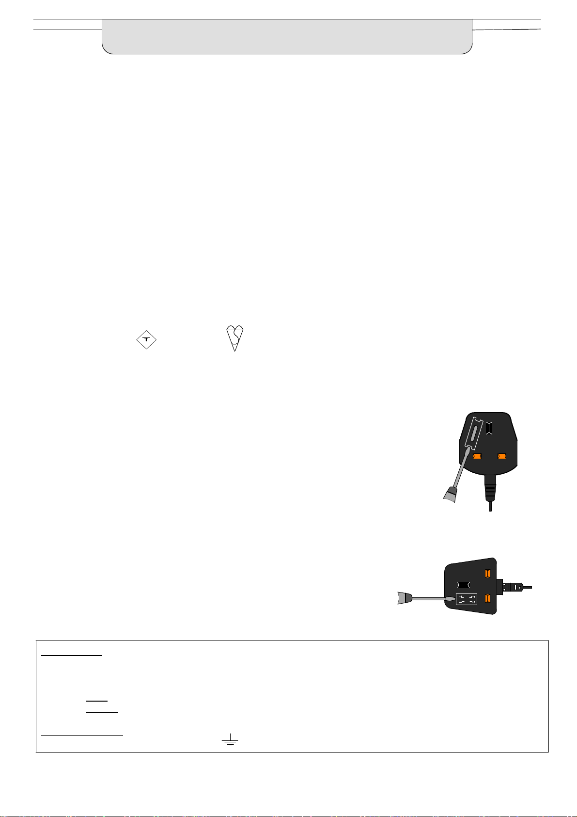
How to replace the fuse (for plug type shown in example 1) :
Lift out the removable fuse compartment with a screwdriver and replace the fuse, then refit
securely into the mains plug (see example 1).
How to replace the fuse (for plug type shown in example 2) :
Liftopen thefuse compartment,in the mains plug,with a screwdriver, and replace the fuse,
then press the fuse cover down securely (see example 2).
Example 1
Example 2
IMPORTANT :-- The wires in the mains lead of this appliance are colouredin accordance with the following code :--
BLUE : NEUTRAL BROWN : LIVE
Asthecoloursofthewiresin themainsleadof thisappliancemaynotcorrespondto themarkingsidentifyingtheterminalsin yourplug,
proceed as follows :--
1. The BLUE wire must be connected to the terminal marked ‘N’ or coloured black.
2. The BROWN wire must be connected to the terminal marked ‘L’ or coloured red.
IMPORTANT NOTE : Under no circumstancesshouldeither of these wires be connectedto the Earth terminal of the three pin plug,
marked with the letter ‘E’ or the earth symbol.
3
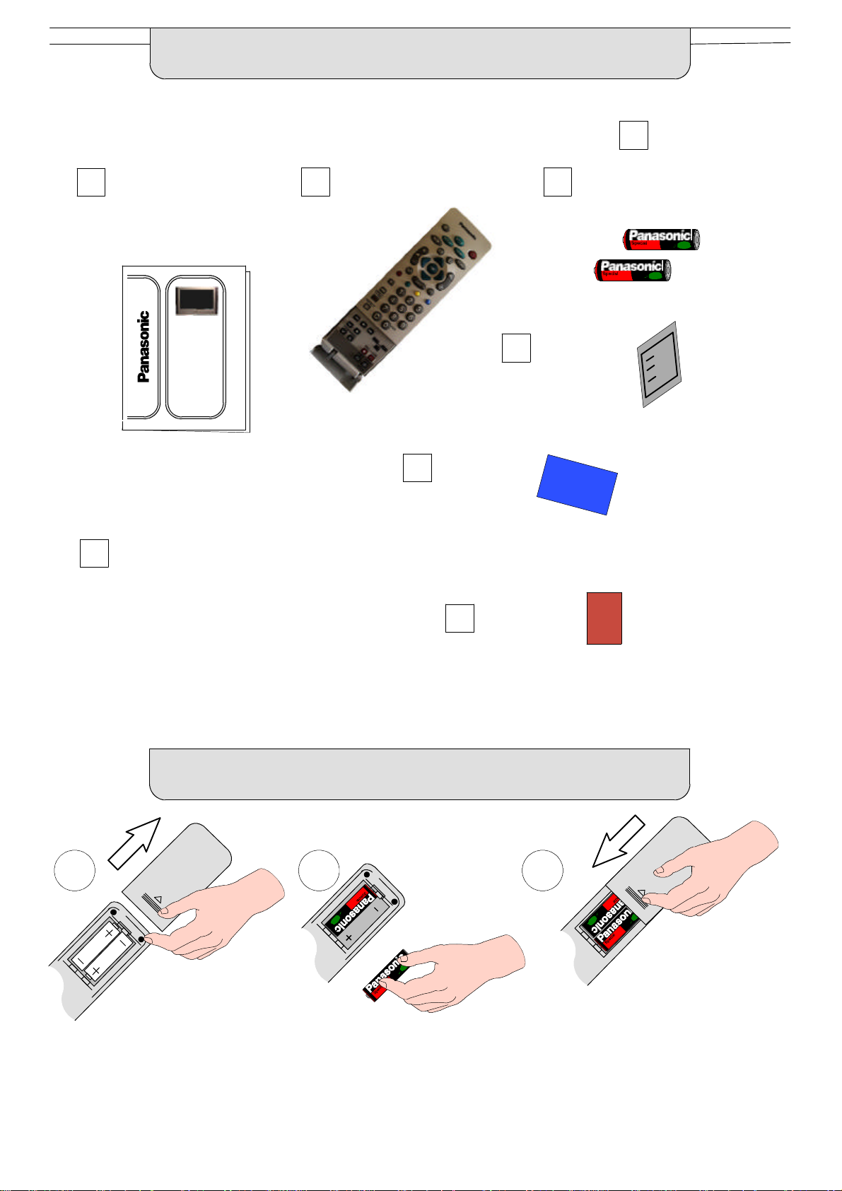
ACCESSORIES
Check that you have the accessories and items shown
Operating Instructionbook
TQB8E3521
TX--32DT30
TX--28DT30
VS- -32PL / VS- -28PL
(Video cabinet)
Remote ControlTransmitter
EUR511241
CRT Guarantee
n
Batteriesfor the Remote Control
Transmitter.
(2 x R6 (UM3) size)
TV Guarantee
Questionnaire
INSERTING THE REMOTE CONTROL BATTERIES
1 2 3
Slide off the battery cover Insert batteries -- note correctpolarity
(+ and --)
Replace the cover
Notes:
D Make sure that the batteries are fitted the correct way round.
D Do not mix old batteries with new batteries. Remove old, exhausted batteries immediately.
D Do not mix different battery types, i.e. Alkaline and Manganese. Do not use rechargeable (Ni--Cad) batteries.
4
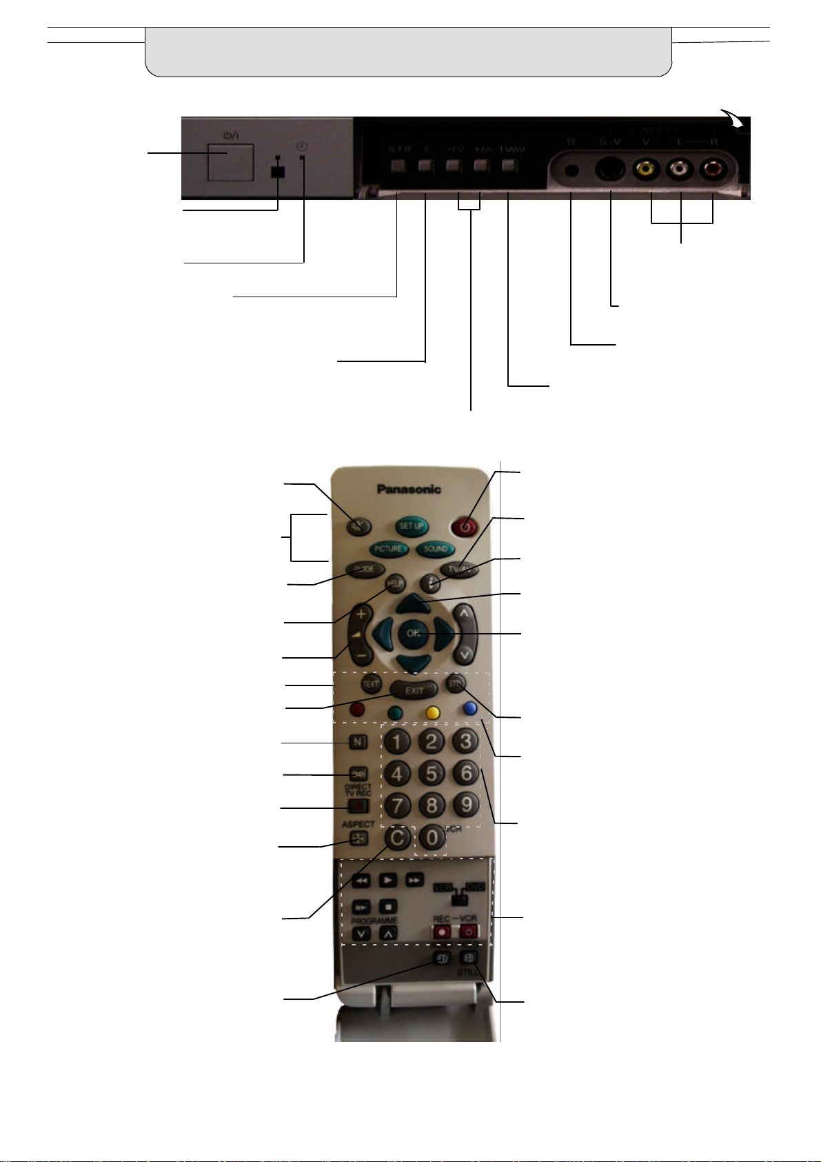
BASIC CONTROLS :
FRONT PANEL AND REMOTE CONTROL
MAINS Power
On/Off switch
Indicator LED’s:
Red indicates
Standby mode;
Orange indicates DVB systemactive for recording or DVB
tuner lock on.
STR (Normalisationstore)
Used to store tuning and other
function settings
Press here and open flap to expose TV controls, front AV3 and headphone terminals
RCA Audio/Video
sockets (page 46)
S--VHS socket
(see page 46)
F (Function select)
Displays the On Screen Display functions, use
repeatedly to select from the available functions
-- Volume, Contrast,Brightness, Colour,
Sharpness, Tint (in NTSC mode), Bass, Treble,
Balance, Tuning mode
(only when viewing analogue transmissions)
and Geomagnetic Correction
Sound mute On/Off
Menu buttons
Press to access the Picture, Sound
and Setup menus (see page 13)
Displays the DVB TV Guide
(see page 36)
The Help button provides a demonstration
of On Screen Display menus
Volume increase / decrease (see page 12)
Teletext buttons (see page 43)
Exits the menu system
The N button will recall settings
stored with OK
Ambience on/off
Direct TV Record button
(see page 40)
Aspect control button
(see page 14)
Headphone socket
(see page 46)
TV/AV switch (see page 38)
Increases or decreases the programme position by one. When a function is
already displayed, press to increase or decrease the selected function
Standby On/Off switch
Switches TV On or Off standby
Switches DVB system on or off
standby if tuner lock is not set
Switch between viewing TV or AV input
(see page 38)
Shows status information for the current
Programme position
Cursor buttons to make selections and
adjustments.
OK button to confirm selections and choices.
Press after selecting programme positions
1--19 to avoid delay
Channel number up and down, Teletext page
selection (see page 12)
Displays subtitles (if available)
Multi function buttons used for
Teletext functions (see page 43)
AV selection (see page 38)
Programme / channel change buttons - press the OK button after selecting
programme positions 1- -19 to avoid delay;
Teletext page buttons (see page 43); when in
Standby mode, switches TV on
Direct channel access
During normal TV viewing or when in the
Tuningmenu, press and then enter
channel number using the numeric
buttons
Selects the nearest teletext index page
(see page 43)
VCR / DVD buttons
(see page 42)
Freezes the current teletext page
(see page 43)
Stills the picture, press again to
return to watching the current
programme
5
QUICK START GUIDE
Connection and setting up options
1. If connecting the TV using an RF cable only,proceed to option 1.
2. If connecting the TV using Scart and RF cables, proceed to option 2.
3. If connecting the TV to a Q--Link (or Q--Link compatible) VCR, proceed to option 3 on page 7.
4 If connecting the TV to a Q--Link (or Q- -Link compatible) VCR, and a satellite receiver, proceed to option 4 on page 8.
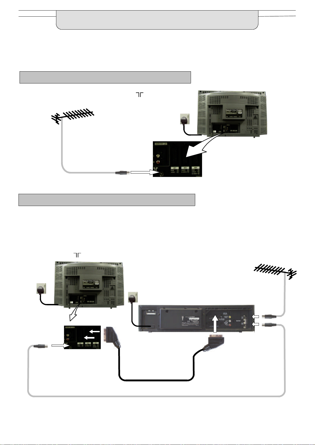
1. Connection of TV using an RF cable only
RF Connection
D Connect the RF cable into the TV Aerial socket ( ).
Mains
Socket
Aerial
Input
socket
If you experience reception problems,
especially when viewing DVB services,
see page 49 for alternative methods of
aerial connection.
2. Connection of TV and VCR using Scart and RF cables
Scart Connections
D The VCR can also be connected to the TV using a Scart cable if you are using a Scart equipped VCR.
D Use the TV’s AV1 Scart socket for a VCR.
D Use the TV’s AV2S Scart socket for an S- -Video VCR.
RF Connection
D Connect the RF cable to the Aerial In socket of the VCR and an RF cable from the VCR Aerial Out socket to the
TV Aerial socket ( ).
TV
Mains
Socket
AV1 and AV2
Scart sockets
Aerial
Input
socket
Mains
Socket
VCR
AV1
Scart socket
Aerial
Input
socket
Aerial
Output
socket
Notes :
Additional equipment and cables are not supplied.
Further details of Audio/ Video connections can be found on pages 46 and 47.
6
If you experience reception problems,
especially when viewing DVB services,
see page 49 for alternative methods of
aerial connection.
Whenusinga“
”
VCRthemainfeaturespossiblearethefollowing
:
QUICK START GUIDE
What is Q--Link ?
Q--Link allows direct communication between the TV and a Q--Link (or Q--Link compatible) VCR, this will enable features such as
downloading of tuning information from the TV to the VCR.
NEXTVIEWLINK
D PresetDownload -- Downloading of tuning information from the TV to the VCR.
D Direct TV Record -- For immediate recording of the current program (What You See Is What You Record).
When using a “Q--Link” VCR the main features possible are the following :
D PresetDownload -- Downloading of tuning information from the TV to the VCR.
D Direct TV Record -- For immediate recording of the current program (What You See Is What You Record).
D TV/VCRAuto Power On -- When the VCR plays a tape the TV will automatically switch On and select the AV2 input.
D VCRAuto Power Standby -- When the TV is switched into Standby, the VCR will also switch into Standby.
D VCRImage view On -- If the TV is in Standby mode and the VCR sends a menu to be displayed on the TV screen
(e.g. Main menu), the TV will automatically switch On and the menu will be displayed.
This TV will also communicate with other VCR’s that bear the following logos :
D “DATA LOGIC” (a trademark of Metz Corporation).
D “Easy Link” (a trademark of Philips Corporation).
D “Megalogic” (a trademark of Grundig Corporation).
D “SMARTLINK” (a trademark of Sony Corporation).
These VCR’s may support some or all of the above functions. Refer to the VCR operating instruction book.
Further information on Q--Link can be found on page 39.
In order for Q--Link to function correctly, the Scart cables must be connected in a certain way, dependent on whether the TV
is being connected to a VCR (option 3, below) or other external equipment.
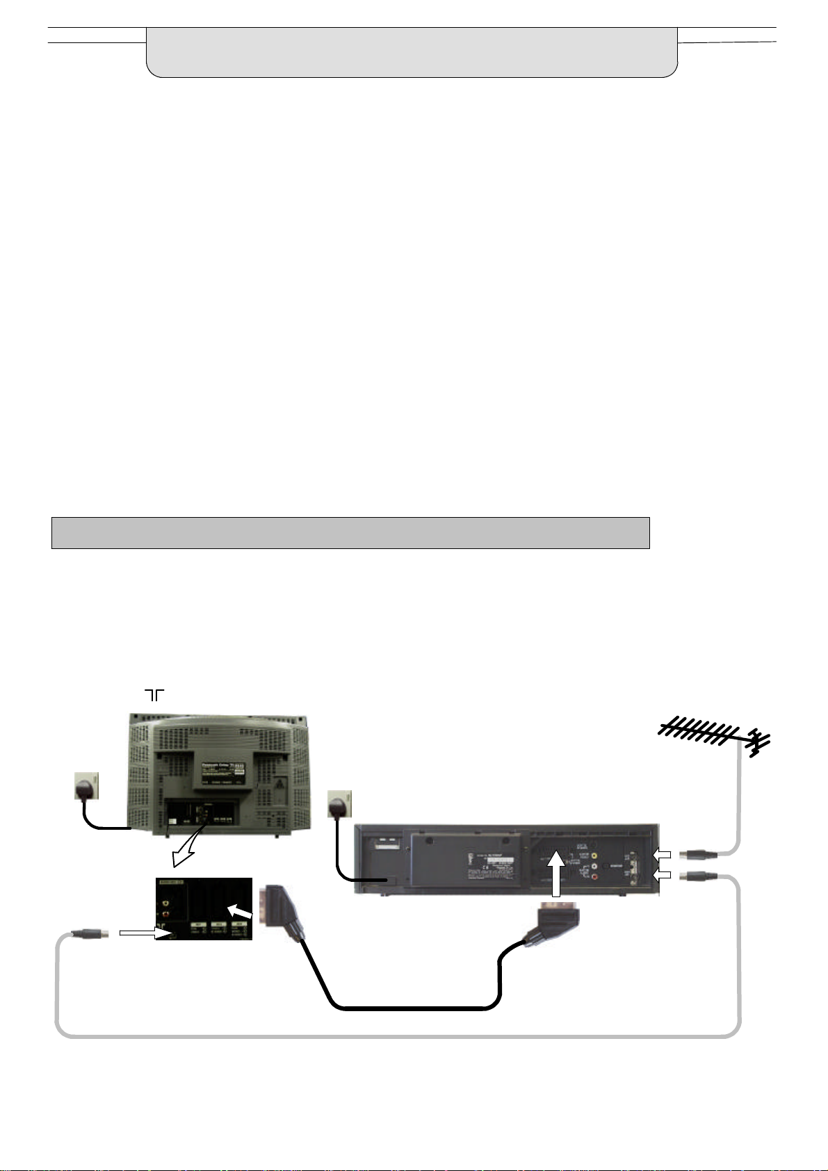
3. Q--Link connection of TV and VCR using Scart and RF cables
Scart Connection
D The VCR must be connectedto the AV2 Scart socket of this TV using a “fully wired” Scart cable.
Note :
If using a “Q--Link” VCR then the AV1 Scart of the VCR must be connected to the AV2 socket of the TV.If your VCR isnot a “Q--Link”
VCR, please consult your VCR operating instruction book.
RF Connection
D Connect the RF cable to the Aerial In socket of the VCR and an RF cable from the VCR Aerial Out socket to the TV Aerial
socket ( ).
TV
Mains
Socket
Aerial
Input
socket
Mains
Socket
VCR
AV1
Scart socket
Aerial
Input
socket
Aerial
Output
socket
AV2 Scart
socket
If you experience reception problems,
especially when viewing DVB services,
see page 49 for alternative methods of
aerial connection.
Notes :
Additional equipment and cables are not supplied.
Further details of Audio/ Video connections can be found on pages 46 and 47.
Further information for VCR installation with this TV can be found on page 41.
7
QUICK START GUIDE
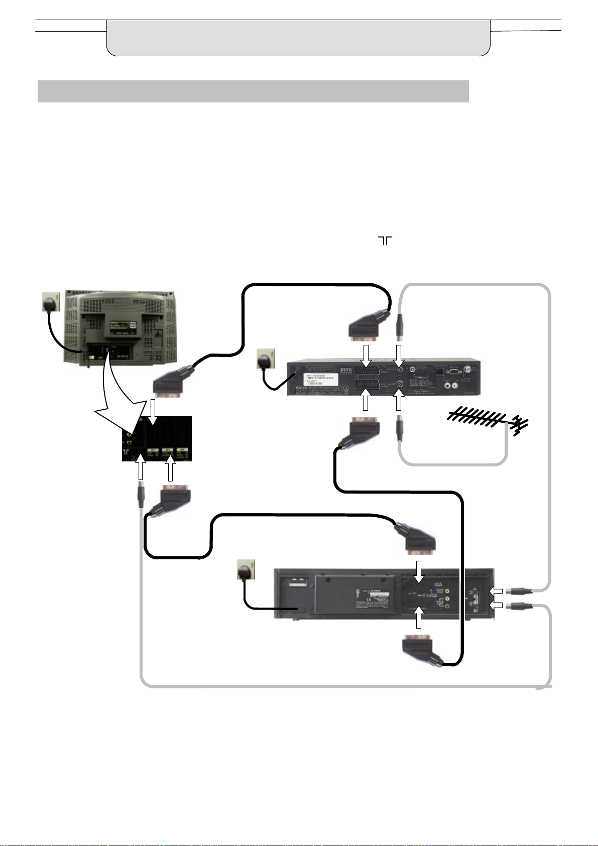
4. Q--Link connection of TV and VCR using Scart and RF cables
For Q--Link to function correctly the TV, VCR and Satellite Receiver must be connectedas shown in the diagram below.
Scart connections
’Fully wired’ Scart cables should be used for all of the Scart connections.
D The AV2 Scart of the VCR must be connected to the VCR socket of the Satellite Receiver.
D The TV Scart socket of the Satellite Receiver must be connected to the AV1 Scart socket of the TV.
Note:
D If using a “Q--Link” VCR then the AV1 Scart of the VCR must be connected to the AV2 socket of the TV. If your VCR is not a
“Q--Link” VCR, please consult your VCR operating instruction book.
RF connections
D Connect an RF cable to the Aerial In socket of the Satellite Receiver.
D Connect an RF cable from the RF Out socket of the Satellite Receiver to the RF In socket of the VCR.
D Connect an RF cable from the RF Out socket of the VCR to the TV Aerial In socket ( ).
Mains
Socket
Aerial
Input
socket
TV
AV1 Scart
socket
AV2 Scart
socket
Mains
Socket
Mains
Socket
VCR
TV Scart
socket
VCR Scart
socket
AV1
Scart socket
Aerial
Output
socket
Satellite
Receiver
Aerial
Input
socket
Aerial
Input
socket
AV2
Scart socket
Notes:
D Additional equipment and cables are not supplied.
D Further details of audio/ video connectionscan be found on pages 46 and 47.
D Further information for VCR and Satellite Receiver installation with this TV can be found on page 41.
8
Aerial
Output
socket
QUICK START GUIDE
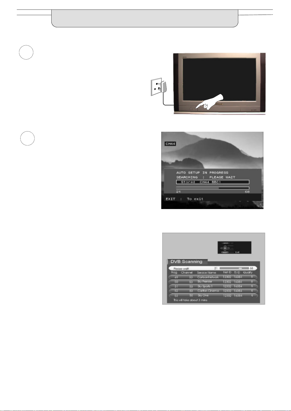
1
Ensure that the VCR is in Standby mode.
Plug the TV into mains socket and switch ON.
Programmes will appear immediately if your dealer
2
has programmed the TV for you.
If the TV has not been programmed for you then
Auto setup will begin.
First, the TV will search for analogue stations:
Mains
Socket
When the search for analogue stationsis complete, the
TV will continue to search for DVB stations.
TV stations will be located, sorted into order and stored
ready for use.
Stations are sorted into the following order:
D DVB Stations: Are sorted by their logical channel number.
followed by:
D Analogue Stations: All analogue stations, sorted into channel order.
The sorted programme order depends upon the TV signal, the broadcasting system, and reception conditions.
9
QUICK START GUIDE
TV to VCR Download
3
If a “Q--Link”, “NEXTVIEWLINK” or compatible VCR
has been connected to the AV2 socket before
starting Step 1, programme information will be
downloaded to the VCR.
Only the analogue programme positions will be
downloaded to the VCR, in the correct order.
See page 39.
Not all VCRs support this download of
programme information, some may require to be
started manually.
Refer to the VCR operating instruction book.
If a VCR other than those described above has
been connected, then there will be no download
operation, the TV is now ready for use:
Notes :
If the VCR has not accepted download data from the TV,
you may need to select the Download option from the
VCR’s menu system.
Refer to the VCR operating instruction book.
TV > VCR DOWNLOAD IN PROGRESS
PLEASE WAIT
PROGRAMME : 48
REMOTE CONTROL UNAVAILABLE
BBC1
4
If Q--Linkisnot operating correctly, check the following:
D The Scart cable is connected to the TV’s AV2 Scart
socket.
D The Scart cable is connected to the VCR’s compatible (Q--Link, NEXTVIEWLINK or similar technology) Scart socket.
D The Scart cable is a “fully wired” type.
For further information on Q--Link and connecting equipment, see pages 39, 46 and 47.
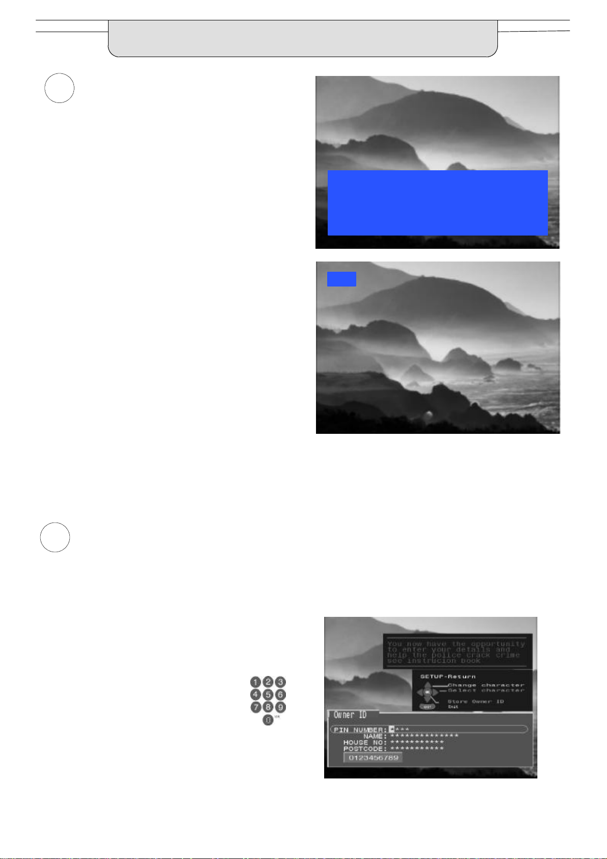
Owner ID
As an added feature, this TV has the option of adding a security code (Owner ID) and personal details into its memory,
so that in the unfortunate event of theft it will help the Police to trace the owner.
Enter required 4 digit Owner ID
PIN NUMBER.
(using 0 to 9 on the remote control).
10

QUICK START GUIDE
5
Enter NAME, HOUSE NUMBER and POSTCODE.
If a 4 digit PIN NUMBER was entered
above, you will be taken automatically to
the NAME line.
If not, move to the NAME line.
Change character.
Select character position.
Repeat above until NAME, HOUSE
NUMBER and POSTCODE are entered.
Press OK to store the details.
Press OK again, when you are asked
“Are you sure ?”
For further information on Owner I.D., see page 24.
A space is provided on page 24 to write down the PIN
NUMBER for future reference.
To view a list of the stations that have
6
been found, press the GUIDE button on
the remote control (see page 36).
DVB stations are shown with a n in the
DVB column, while analogue stations
are denoted by their transmission
channel number.
Use the cursor buttons to move the
cursorbar up and down the list.
To view the selected programme press
the OK button.
Categories
To make stations easier to find, specific stations can be listed by category; press the left or right
cursorbutton to choose a category. The chosen category name is shown at the top of the menu.
For example, if you select ‘Free TV’, only ‘free- -to- -air’ stations will be listed - - you can view any of these now.
If you select ‘Pay TV’, only subscription stations will be listed - - you will need to contactthe service provider to find
out how to subscribe to these stations.
11
QUICK START GUIDE
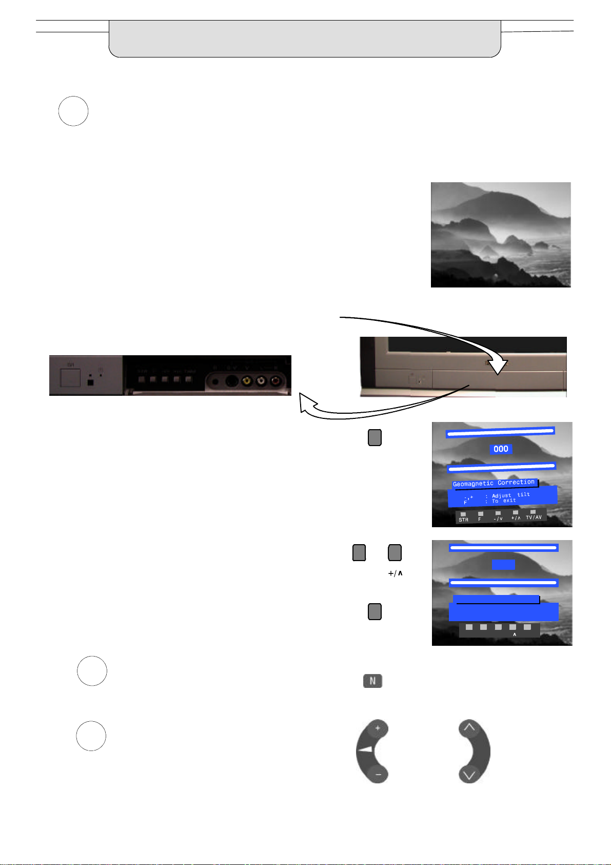
Slight tilting of the picture may be noticeable or colouredpatches may sometimes appear at the corners of the
7
screen (colour purity). The Geomagnetic Correctionfeature can be used to eliminate them, if necessary:
First, ensure the Auto setup and Q- -Link download procedures are
complete. The screen should not be showing any On- -Screen Display
menus.
Open the flap on the television’s front panel
Press and release here to open flap
Press the F button repeatedly until the Geomagnetic
Correction feature is displayed
Press the + or -- buttons repeatedly until the picture
appears to be level
Press the F button again to return to normal viewing.
Close the flap to prevent damage
We recommend that as soon as the Auto setup feature
8
is completed, the picture controlsare reset to normal
viewing levels. To do this, press the ”N” button on the
remote control.
--/v
F
002
Geomagnetic Correction
-,+ : Adjust tilt
F : To exit
F
STR F -/v +/ TV/AV
12
You are now ready to begin viewing programmes
9
The side controlsprovide the two basic functions:
Adjust Volume
Change Programme
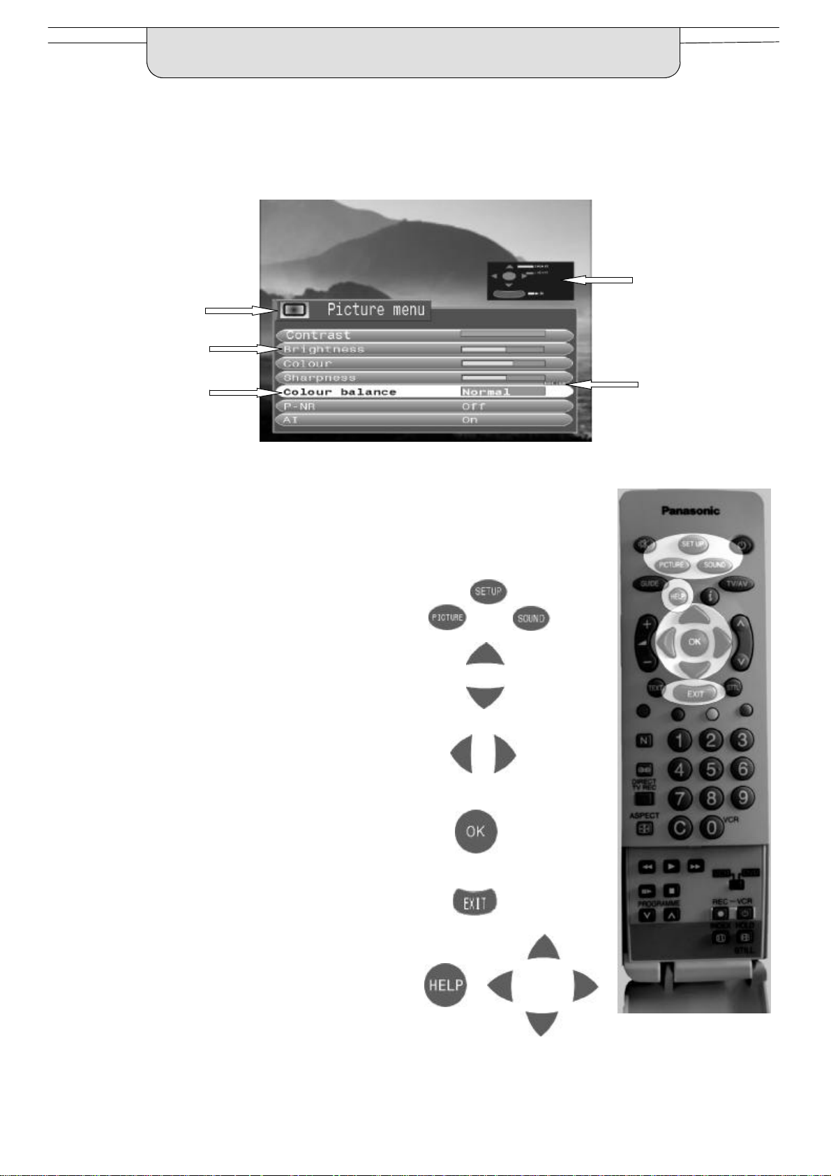
USING THE ON SCREEN DISPLAYS
This TV has a comprehensive system of On Screen Display (OSD) menus to access
adjustments and options
Instructions
Menu Title
Sub--menus
Selection bar
Some selections,for example, Contrast, Brightness, Colour and Sharpness
will allow you to increase or decrease their level.
Some selections, for example, Off timer,allow a change of setting to be made.
Some selections,for example Tuning menu, will lead to a further menu.
The PICTURE, SOUND and SET UP buttons are
used to open the main menus and also to return to
the previous menu.
The up and down cursor buttons are used to move
the cursorup and down the menus.
The left and rightcursorbuttonsareused to access
menus, adjust levels or to select from a range of
options.
Indicator for options
The OK button is used to store settings after
adjustments have been made or options have
been set, for example Pictureand Sound settings.
The EXIT button is used to exit the menu system
and return to the normal viewing screen.
The HELP button will run a demonstration of the
menus available. During normal viewing, with no
OSDs displayed, press the HELP button and
select one of the options.
13
ASPECT CONTROLS
The widescreen TV will allow you to enjoy viewing the picture at its optimum size and aspect,
including widescreen ‘cinema format’ pictures.
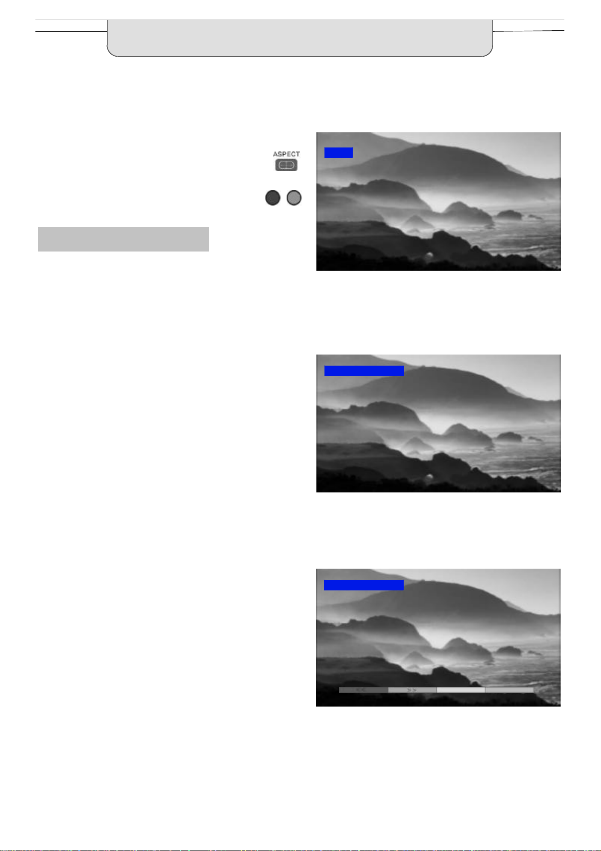
Press the ASPECT button repeatedly to move
through the seven aspect options: Panasonic
Auto, 16:9, 14:9, 4:3, Zoom1,Zoom2 and Zoom3.
OR
Press the ASPECT button then use the RED or
GREENbuttonstomoveineitherdirectionthrough
the seven aspect options.
Panasonic Auto
Panasonic Auto determines the best aspect ratio to
use to fill your screen. It does this using a four step
process to determine if the picture being viewed is a
widescreen picture.
If Panasonic Auto detects a widescreen signal it
switchesintotheappropriate16:9or14:9widescreen
mode. If Panasonic Auto does not detect a
widescreen signal then this advanced TV set
enhances the picture for optimum viewing pleasure.
WIDE
’WIDE’ appears in the top left of the screen, Panasonic Auto
switchesto the appropriate 16:9 or 14:9 widescreen ratio.
Panasonic Auto
The text shown on the screen indicates how
Panasonic Auto determined which ratio to use:
’WIDE’ appears in the top left of the screen if a
widescreeen identification signal (WSS) is found or a
signalfound through a Scartsocket.PanasonicAuto
switches to the appropriate 16:9 or 14:9 widescreen
ratio
’PanasonicAuto’appearsin thetopleftofthe screenif
black stripes above and below the picture are
detected.Panasonic Auto choosesthe best ratioand
expandsthepicturetofill the screen.This processcan
take several minutes, depending on the darkness of
the picture.
You may prefer to manually select one of the other
aspect options available to view the picture.
Notes:
D If, in Panasonic Auto mode, you experience
problems with the screen display size when
playing back widescreen format recordings from
your VCR then it is possible that the tracking
control of your VCR requires adjustment (your
VCR instruction book will contain adjustment
details).
D The widescreen aspectratiosofdifferentfilmsand
programmes can vary. If these are wider than a
standard 16:9 aspect picture then a black band
maybe visibleatthe top and bottomof thescreen.
’PanasonicAuto’ appears in the top left of the screen,
The best ratio is chosen and the picture expanded to fill the screen.
Panasonic Auto
Press the ASPECT button, then use the RED or GREEN buttons to
move in either directionthrough the seven aspect options.
14
ASPECT CONTROLS
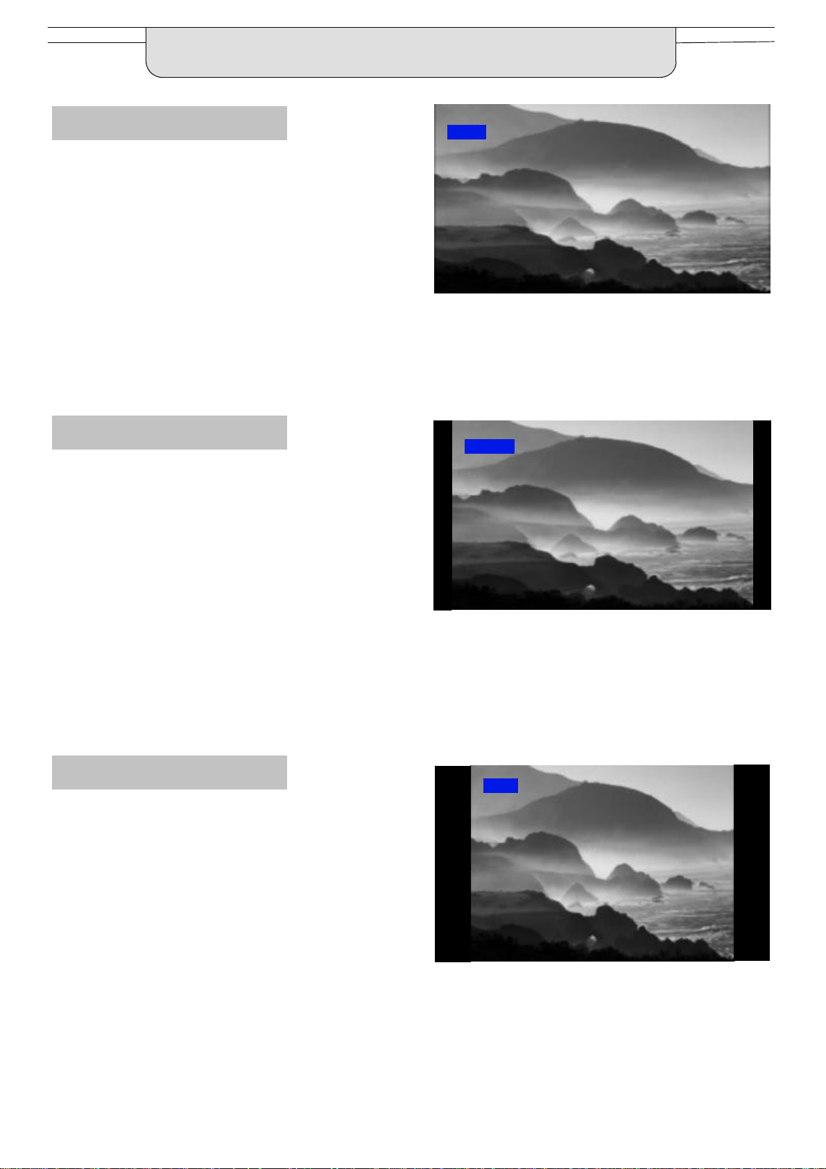
16:9
16:9 will display a true 16:9
(anamorphic)picturewith noaspect
distortions.
14:9
14:9 will display a 14:9 letterboxor4:3
picture with no aspect distortions.
16:9
16:9
14:9
4:3
4:3 will display a 4:3 picture at its
standard 4:3 size with no aspect
distortions.
14:9
4:3
4:3
15
ASPECT CONTROLS
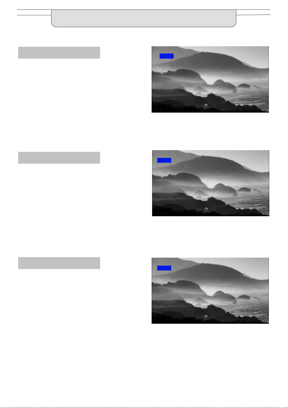
Zoom1
Zoom1 will display 16:9 letterbox or
4:3 pictures with no aspect
distortions
Zoom2
Zoom2willdisplay16:9anamorphic
letterbox pictures as a full screen
display with no aspect distortions
Zoom1
Zoom1
Zoom2
Zoom3
Zoom3 will display 21:9 letterbox
picturesas a full screen display with
no aspect distortions
Zoom2
Zoom3
Zoom3
16
 Loading...