

Panasonic TX-26LX500A, TX-32LX500A User Manual
OK
123
456
7
89
0
TV
Operating Instructions
Wide LCD TV
Model No.
TX-26LX500A
TX-32LX500A
The illustration shown is an image.
Please read these instructions before operating your set and retain them for future reference.
English
TQBC2050
Dear Panasonic Customer
Welcome to the Panasonic family of customers. We hope that you will have
many years of enjoyment from your new LCD TV.
To obtain maximum benefit from your set, please read these Instructions before
making any adjustments, and retain them for future reference.
Retain your purchase receipt also, and note down the model number and serial
number of your set in the space provided on the back cover of these instructions.
Contents
Warnings and Precautions ........................................ 3
Accessories ............................................................... 5
Fitting remote control batteries ................................. 5
Cable cover removal and fitting ................................ 5
How to open the front cover ...................................... 6
How to use the LCD stand ........................................ 6
How to hang the LCD TV on the wall ........................ 6
Antenna connection .................................................. 6
Audio / Video connections......................................... 7
How to connect the Headphones/AV3 terminal ..... 7
How to connect the Monitor Output
terminals to other Equipment ...................... 8
How to connect the AV1/2 Input terminals ............. 8
How to connect the DVD (AV4) Input terminals ..... 8
How to connect the HDMI Input terminals ............. 9
How to connect the PC Input terminals ............... 10
Power On / Off ........................................................ 10
Basic controls: front panel and remote control .........11
Using the On Screen Displays ................................ 12
Tuning ..................................................................... 13
Tuning menu ........................................................ 13
Auto tuning .......................................................... 14
Trademark Credits
• VGA is a trademark of International Business Machines Corporation.
• Macintosh is a registered trademark of Apple Computer, USA.
• S-VGA is a registered trademark of the Video Electronics Standard Association.
Even if no special notation has been made of company or product trademarks, these trademarks have been
fully respected.
• SD Logo is a trademark.
• HDMI, the HDMI Logo and High-Definition Multimedia Interface are trademarks or registered trademarks of
HDMI Licensing LLC.
Auto tuning (via front panel) ................................ 14
Manual tuning ...................................................... 15
Manual tuning (via front panel) ............................ 15
Channel Allocation .................................................. 16
Picture menu ........................................................... 17
Sound menu ............................................................ 18
Setup menu ............................................................. 19
ASPECT Controls ................................................... 20
MULTI PIP............................................................... 21
PC mode ................................................................. 22
Card operations ...................................................... 24
Still .......................................................................... 31
Teletext operation .................................................... 32
VCR / DVD operation .............................................. 34
Stereo / Bilingual Sound Selection .......................... 35
Remote control setting ............................................ 35
Troubleshooting ...................................................... 36
Maintenance ........................................................... 37
Input signal that can be displayed ........................... 37
Specifications .......................................................... 38
WARRANTY............................................... back cover
This product incorporates copyright protection technology that is protected by U.S. patents and other intellectual
property rights. Use of this copyright protection technology must be authorized by Macrovision Corporation,
and is intended for home and other limited viewing uses only unless otherwise authorized by Macrovision
Corporation. Reverse engineering or disassembly is prohibited.
U. S. patent No. 4,907,093.
2
Warnings and Precautions
In explanations below, the type of contents which should be observed is classified by the following picture indications.
: “Prohibition” which must not be carried out
: “Directions” which should be followed
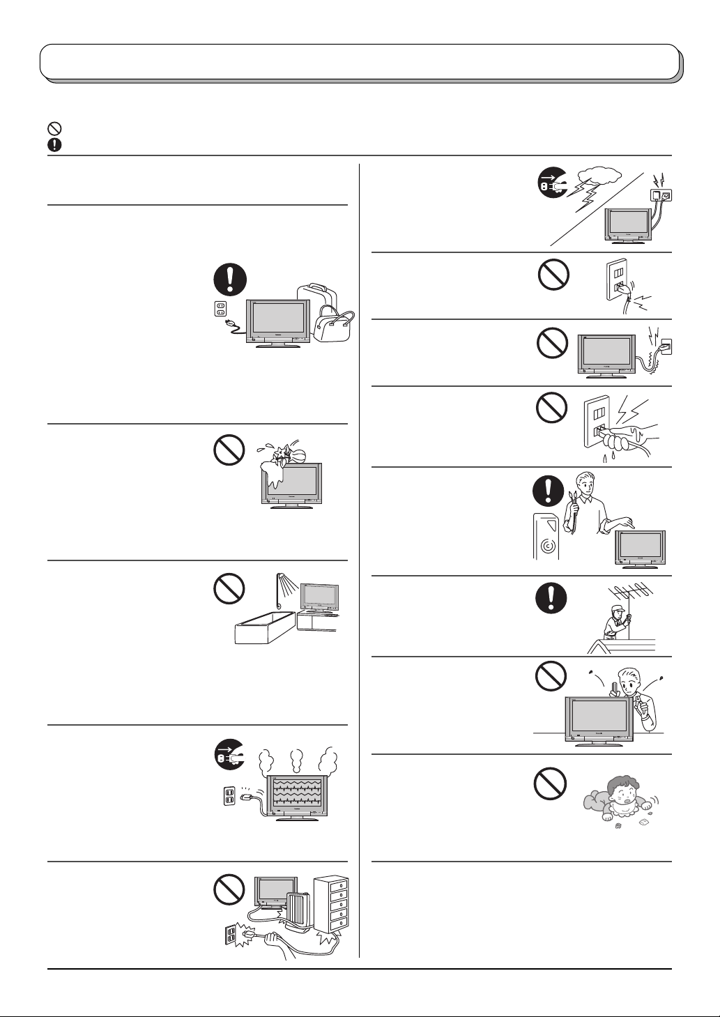
• This TV set is designed to operate on AC 110-127 /
220-240 V, 50 / 60 Hz.
• The On / Off switch on this model does not fully
disconnect the TV from the mains supply.
Remove the mains plug
from the wall socket before
connecting or disconnecting
any leads, or if the TV set is
not used for a prolonged
period of time.
Note:
If the set is not switched off when the TV station stops
transmitting, it will automatically go to Standby mode
after 30 minutes. This function will not operate when
the TV is in AV mode.
• To prevent damage which
might result in electric shock
or fire, do not expose this TV
set to rain or excessive
moisture. This TV must not
be exposed to dripping or
splashing water, and objects
filled with liquid, such as vases, must not be placed
on top of or above the TV.
• DO NOT use this unit near
water. (Near a bath tub, etc.)
Refer all servicing to
qualified service personnel.
Servicing is required when
the apparatus has been
damaged in any way, such as power-supply cord or
plug is damaged, liquid has been spilled or objects
have fallen into the apparatus, the apparatus has been
exposed to rain or moisture, does not operate normally,
or has been dropped.
•
Unplug the power cord in the
event of any malfunction
(screen goes blank, no
sound, odd sounds, smoke or
unusual odours coming from
the unit).
Unplug the power cord if
foreign matter or water falls into the unit, or if the unit
is dropped or the cabinet is damaged.
• DO NOT touch the aerial
cable and this unit when
there is lightning.
• DO NOT use if the power
cord or power plug is
damaged, or if the plug does
not fit tightly into the socket.
• DO NOT use at a voltage
other than indicated.
• DO NOT touch the power
plug if your hands are wet.
• Turn the power “Off”
before connecting other
electrical equipment.
• Ask your sales outlet to
install the aerial.
•
WARNING : HIGH VOLTAGE
Do not remove the rear
cover as live parts are
accessible when it is
removed. There are no user
serviceable parts inside.
• WARNING
Keep unneeded small parts
and other objects out of the
reach of small children. These
objects can be accidentally
swallowed. Also, be careful
about packaging materials and plastic sheets.
!!!
• TAKE CARE NOT to
damage the power cord.
• Refer all servicing to qualified service personnel.
Servicing is required when the apparatus has been
damaged in any way, such as power-supply cord or
plug is damaged, liquid has been spilled or objects
have fallen into the apparatus, the apparatus has been
exposed to rain or moisture, does not operate normally,
or has been dropped.
3
Warnings and Precautions
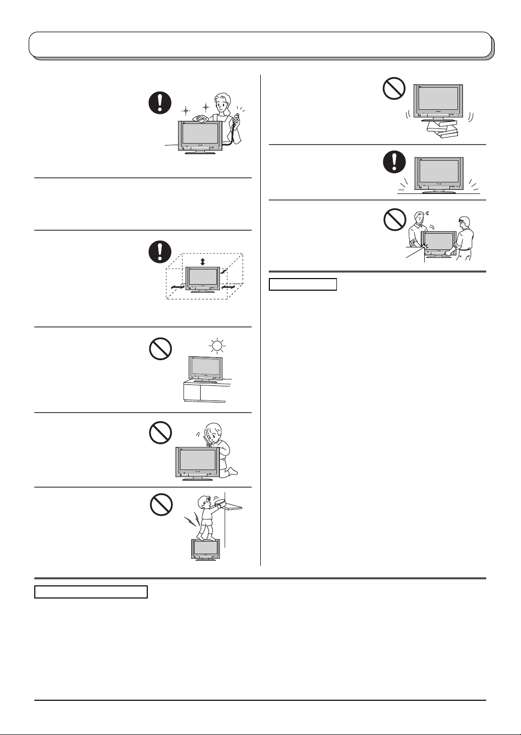
• Cabinet and LCD panel care
Remove the mains plug
from the wall socket. The
cabinet and LCD panel
can be cleaned with a soft
cloth moistened with mild
detergent and water.
Do not use solutions
containing benzol or petroleum.
• When ambient temperature is cool, the picture may
take a short time to reach normal brightness, but this
is not a malfunction. (After brief moment, the picture
will have normal brightness.)
• Adequate ventilation is
essential to prevent failure
of electrical components,
we recommend that a gap
of at least 10cm is left all
around this TV set even
when it is placed inside a
cabinet or between shelves.
• Avoid exposing the TV set
to direct sunlight and other
sources of heat. To
prevent fire, never place
any type of candle or
naked flame on top or
near the TV set.
• DO NOT insert foreign
objects (metal or easily
flammable objects).
• DO NOT stand, or place
heavy objects on the unit.
Particular care should be
taken by families with
small children.
• DO NOT place in an
unstable location.
• Place in a safe location.
• DO NOT jolt the unit.
Preparation
• Receiver Location
Locate for comfortable viewing. Avoid placing where
sunlight or other bright light (including reflections) will
fall on the screen.
Use of some types of fluorescent lighting can reduce
remote control transmitter range.
Adequate ventilation is essential to prevent internal
component failure. Keep away from areas of excessive
heat or moisture.
To insure optimum picture do not position magnetic
equipment (motors, fans, other speakers, etc.) nearby.
• Optional External Equipment
The Audio / Video connection between components
can be made with shielded video and audio cables.
For best performance, we recommend 75 Ω coaxial
aerial cable is used. Cables are available from your
dealer or electronic supply store.
Before you purchase any cables, be sure you know
what type of output and input connectors your various
components require. Also determine the length of cable
you will need.
• For optimum quality picture
When the LCD is exposed to light from outdoors or
lighting fixtures, high-contrast pictures may not be
displayed clearly. Turn off florescent lamps near the
LCD and place in a location not exposed to outdoor
light.
Pixel Statement (LCD)
An image on an LCD panel is created by many dots known as pixels. The more pixels on the panel, the more
detailed image can be displayed. To create a colour image each pixel is made up of three tiny coloured dots (1 each
of red, green and blue). This gives a total far in excess of one million individual dots manufactured into the panel.
Each one of these dots is precisely controlled by the electronics of the TV to produce the picture.
Whilst Panasonic maintains the highest standards in manufacturing technology and processes in the construction
of these panels, there are a number of allowable Pixel/Dot failures that would still allow the panel to be defined as
a good panel. It is not possible to guarantee absolutely no pixel loss.
4
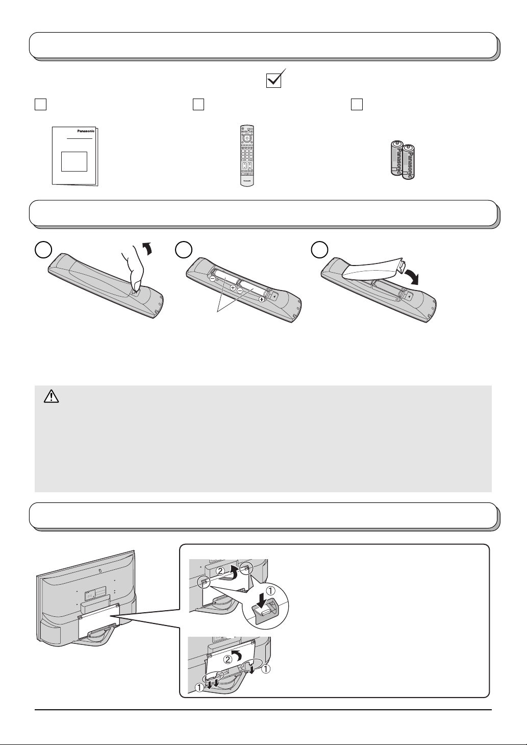
Accessories
Check that you have the accessories and items shown
Operating Instructions Remote Control Transmitter
(N2QAJB000156)
Batteries for the Remote
Control Transmitter
(2 × R6 (AA) size)
OK
123
456
7
89
0
TV
Fitting remote control batteries
1 2 3
“R6 (AA)” size
Pull and hold the hook, then
open the battery cover.
Insert batteries - note correct
polarity ( + and
-
).
Do not use rechargeable (Ni-Cad) batteries.
They are different in shape and performance and may fail to ensure correct operation.
Battery cautions
The incorrect use of batteries can cause electrolyte leakage which will corrode the Remote Control or cause
the batteries to burst.
Observe the following precaution:
1. Batteries shall always be replaced as a pair. Always use new batteries when replacing the old set.
2. Do not combine a used battery with a new one.
3. Do not mix battery types (example:“Zinc Carbon” with “Alkaline”).
4. Do not attempt to charge, short-circuit, disassemble, heat or burn used batteries.
5. Battery replacement is necessary when remote control acts sporadically or stops operating the TV set.
Replace the cover.
Cable cover removal and fitting
E.
ID
S
N
,
I
R
S
T
VE
R
O
A
C
P
E
E
D
V
L
E
O
B
I
A
M
F
I
E
E
L
C
R
A
I
U
V
T
Q
O
ER
N
O
S
T
.
O
-
Y
D
G
L
N
ER
I
ON
S
C
I
U
L
V
E
R
O
N
E
N
N
S
O
R
S
E
R
F
E
E
P
R
E
ay
C
m
I
V
it
n
ER
u
S
e
h
,
t
n
f
e o
ratio
c
e
a
f
p
r
o
u
A
∗
s
g
∗
∗
al.
h
:
.
rin
s
g
p
rm
u
∗
0
m
o
0
ou
A
d
5
.
n
h
x
X
m
a
L
T
2
M
is
3
-
ar
z
X
H
T
0
:
on
.
/6
o
0
iti
N
5
.
l
eel w
d
-
e
d
-
f
t
d
n
L
o
o
0V
M
4
.,
c
2
o
-
0
C
0
is
l
2
Removal
/
a
h
t
ri
n
27
t
a
1
s
-
p
0
a
V
0
du
J
1
T
n
I
:
n
D
i
g
c
C
i
n
i
r
L
e
t
t
d
a
c
a
R
le
r
e
E
M
w
a
o
t
i
P
h
s
su
n
t
a
a
p
M
Ja
a
k
a
s
O
:
.
o
N
al
i
r
e
S
DE.
I
TS INS
R
A
D
E
I
F
I
L
REMOVE COVER,
A
ICEABLE P
U
V
R
OT
E
N
O Q
S
T
.
Y
DO
L
R
E
ON
ICING
V
EL
R
N
E
NO US
N
O
y
REFER S
ma
ICE PERS
V
R
E
S
unit
e
of th
face
peration,
A
∗
∗
∗
:
.
s
p
∗
0
m
0
5
. A
x
X
a
L
Though sur
2
M
3
-
arm during o
z
X
H
w
T
:
on is normal.
l
.
60
i
/
o
0
e
N
5
.
l
e
-
e
-
f
td
d
L
o
0V
,
M
4
.
2
condit
-
0
Co
0
l
2
/
a
i
7
this
r
n
2
t
a
1
s
p
u
0
a
V
0
J
1
T
:
Ind
n
D
i
g
c
C
i
n
i
r
L
e
t
t
d
a
c
a
e
M
er R
El
a
t
i
Pow
ush
s
n
t
a
a
p
M
a
J
ka
a
Os
:
.
o
N
l
a
i
Ser
.
E
D
I
S
N
,
I
R
S
E
T
V
R
O
A
C
P
E
D
VE
L
E
O
B
A
FI
I
E
EM
L
C
R
A
I
U
V
R
Q
E
NOT
O
S
T
.
O
-
D
G
LY
R
N
E
I
ON
S
C
I
U
L
V
E
R
O
Fitting
Note:
To avoid interference appearing on
the screen, do not bundle the RF
cable and mains lead together.
N
E
N
N
S
O
R
S
E
R
F
E
E
P
y
R
E
a
C
m
I
V
R
nit
E
u
S
e
h
,
t
n
f
o
ti
e o
ra
c
e
a
f
p
r
o
u
A
∗
s
∗
∗
h
:
.
ring
s
mal.
g
p
r
∗
u
u
0
m
o
0
A
o
d
5
.
n
h
x
X
a
L
T
2
is
M
3
-
z
X
n
warm
T
0H
o
:
.
6
/
o
0
iti
5
N
.
l
eel
d
-
e
d
-
f
t
d
n
V
L
o
o
0
M
4
.,
c
2
o
-
0
C
0
is
l
2
/
h
ia
7
t
r
n
t
a
12
s
-
p
0
a
V
0
du
J
1
n
I
:
D T
in
g
c
C
i
n
i
L
e
t
tr
a
c
ad
R
le
r
e
M
E
a
it
Pow
h
s
u
s
n
t
a
a
p
M
a
J
aka
s
O
:
.
o
N
l
ia
er
S
1. Push down hooks and pull the cover
slightly towards yourself to disengage the
claws (at 3 points).
2. Slowly pull out in the downward direction.
1. Insert the claws (at 3 points) at the bottom
end.
2. Push until it clicks.
5
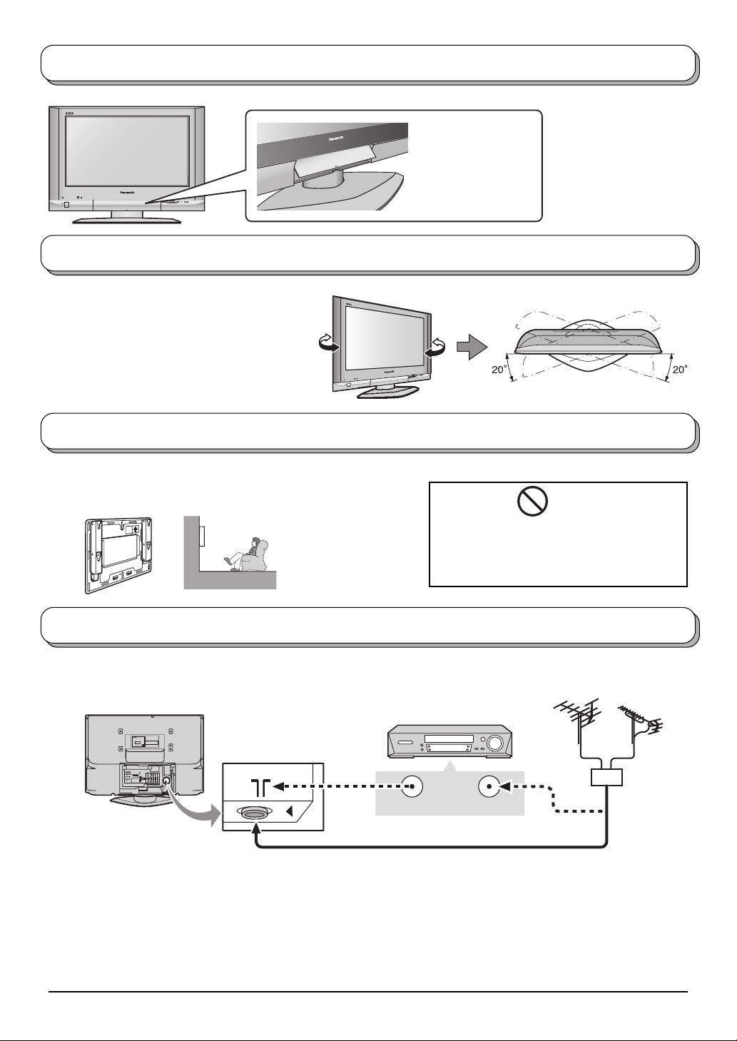
How to open the front cover
Raise the lower part
of the door marked
“PULL”.
How to use the LCD stand
Adjust the LCD panel to your desired angle.
The LCD panel can be adjusted the following
direction:
20° Right
20° Left
How to hang the LCD TV on the wall
This LCD TV is for use only with the following optional accessory.
Wall-hanging bracket ....................... TY-WK32LX20W
•
Always be sure to ask
a qualified technician
to carry out set-up.
WARNING
• DO NOT use other optional accessories.
Use with any other type of optional
accessories may cause instability which
could result in the possibility of injury.
Antenna connection
For proper reception of VHF / UHF channels, an external antenna is required. For best reception, an outdoor
antenna is recommended.
Back of the TV
DO NOT REMOVE COVER,
NO USER - SERVICEABLE PARTS INSIDE.
Model No. : TX-32LX500∗
REFER SERVICING TO QUALIFIED
LCD TV
SERVICE PERSONNEL ONLY.
Power Rating : 100-127/200-240V -- 50/60Hz Max. Amps. : ∗∗∗A
Matsushita Electric Industrial Co., Ltd.
Osaka Japan Made in Japan
Though surface of the unit may
feel warm during operation,
Serial No. :
this condition is normal.
S-VIDEO
U. S. patent No.4, 907, 093.
Y
VIDEO
PB/C
B
MONO MONO MONO
L
PR/C
R
AUDIO
R
MONITOR
AV1INAV2INAV4
COMPONENT
OUT
IN
VCR
ANT INPUTANT OUTPUT
75 Ω Coaxial cable
Notes:
• Additional equipment, cables and adapter plugs shown are not supplied with this TV set.
• To obtain optimum quality picture and sound, an Aerial, the correct cable (75 Ω coaxial) and the correct terminating
plug are required.
• If a communal Aerial system is used, you may require the correct connection cable and plug between the wall
Aerial socket and your TV.
• Your local Television Service Centre or Dealer may be able to assist you in obtaining the correct Aerial system for
your particular area and the accessories required.
• Any matters regarding Aerial installation, upgrading of existing systems or accessories required, and the costs
incurred, are the responsibility of you, the Customer.
6
VHF Aerial UHF Aerial
Mixer
OR
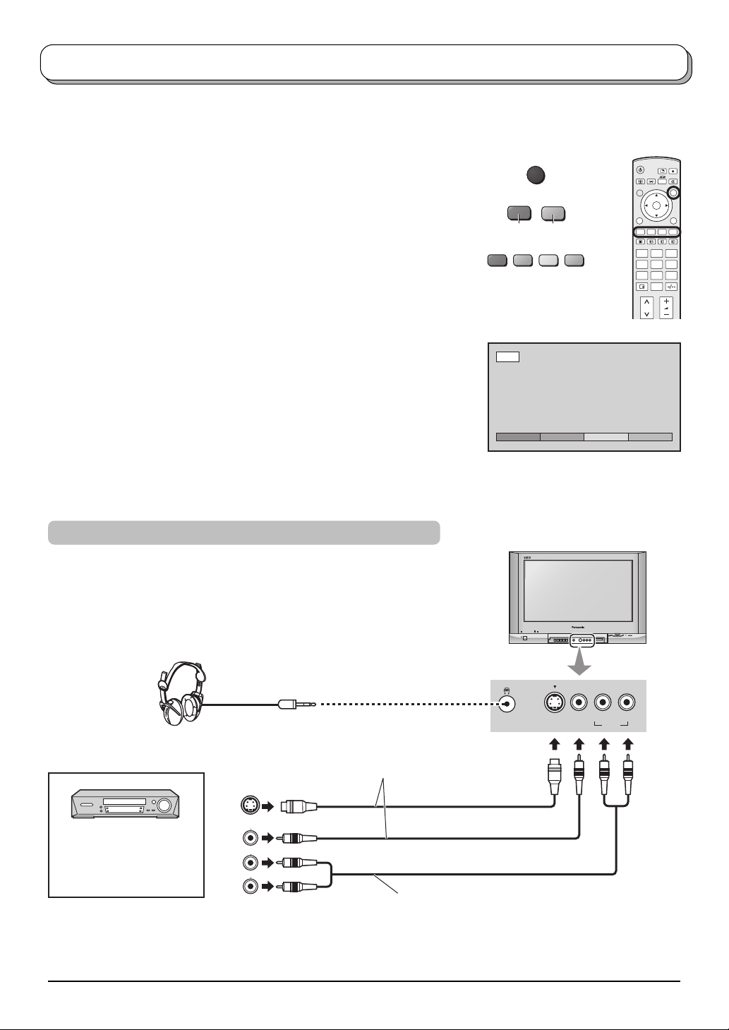
Audio / Video connections
It is possible to connect a variety of additional equipment to this TV. The following pages detail how to connect
external equipment to the front and rear of the TV.
Once your equipment is connected, use the following procedure to view the input:
Press the TV/AV button.
TV/AV
Whilst the on screen selector keys are displayed, select the page by
pressing the Red or Blue button and then press coloured buttons to select
the AV source you wish to view.
Red button : AV1 / Back page
Green button : AV2 / AV4
Yellow button : AV3 / PC
Blue button : Next page / HDMI
The on screen selector keys that appear clear after a few seconds. If you
want to select an input when the keys are not shown, press any coloured
button and the keys will reappear.
Notes:
• You can also select an AV source using the TV/AV button on the
front panel of the TV.
Press the TV/AV button repeatedly until you reach the AV source
you wish to view.
• When a Monaural VCR is used, connect the Monaural Audio cable
to the AUDIO L terminal. (without HDMI, PC)
• Additional equipment and cables shown are not supplied with this
TV set.
How to connect the Headphones / AV3 terminal
BlueRed
AV1
AV1 AV2 AV3 >>
OK
123
456
7
89
0
AV3 I N
(M3 plug)
(Optional)
S VIDEO VIDEO
L/MONO - R
AUDIO
Connect the S VIDEO or
VIDEO terminal.
S VIDEO
VIDEO
AUDIO
VCR / S VIDEO VCR
DVD PLAYER
CAMCORDER /
S VIDEO CAMCORDER
Notes:
S Video
OUT
Video
OUT
Audio
OUT
L
R
To receive monaural output,
connect to AUDIO L/MONO terminal.
• The volume level of the headphones can be adjusted by selecting “Headphone volume” from the Sound menu
(see page 18).
• Additional equipment and cables shown are not supplied with this TV set.
7

Audio / Video connections
How to connect the Monitor Output terminals to other Equipment
Example of output signal source
VCR
MONITOR
VIDEO
IN
L
Amplifier to speaker system
AUDIO
IN
R
How to connect the AV1/2 Input terminals
Example of input signal source
VCR
S VIDEO VCR
S VIDEO
DVD PLAYER
CAMCORDER
OUT
VIDEO
OUT
AUDIO
OUT
L
R
To receive monaural output,
connect to AUDIO L/MONO terminal.
Connect to VIDEO terminal in
MONITOR OUT.
Connect to AUDIO L and R
terminals in MONITOR OUT.
Connect the S VIDEO
or VIDEO terminal.
S VIDEO
VIDEO
L
AUDIO
MONITOR
OUT
R
MONITOR
S VIDEO 4 pin terminal
Chrominance in
Chrominance earth
S VIDEO
MONO
AV1 / 2 IN
VIDEO
AUDIO
L
R
MONITOR
MONO MONO MONO
AV1INAV2INAV4
OUT
MONO MONO MONO
AV1INAV2INAV4
OUT
COMPONENT
IN
Luminance in
Luminance earth
COMPONENT
IN
Y
PB/C
B
PR/C
R
Y
PB/C
B
PR/C
R
How to connect the DVD (AV4) Input terminals
Example of input signal source
DVD PLAYER
Digital TV-SET-TOP-BOX
(DTV-STB)
Note:
Component input terminals are used for 480i / p, 576i / p, 1080i / 50 Hz,
1080i / 60 Hz or SMPTE295M standard 1250i signal.
AUDIO
OUT
VIDEO
OUT
LR
Y, PB, PR,
OUT
COMPONENT VIDEO OUT
P
R
P
B
Connect the VIDEO or
COMPONENT VIDEO terminal.
To receive monaural output,
connect to AUDIO L/MONO terminal.
Y
8
S VIDEO
VIDEO
L
AUDIO
R
MONO
AV4 IN
MONO MONO MONO
MONITOR
OUT
Y
P
PR/C
AV1INAV2INAV4
B/CB
R
IN
Y
PB/C
B
PR/C
R
COMPONENT
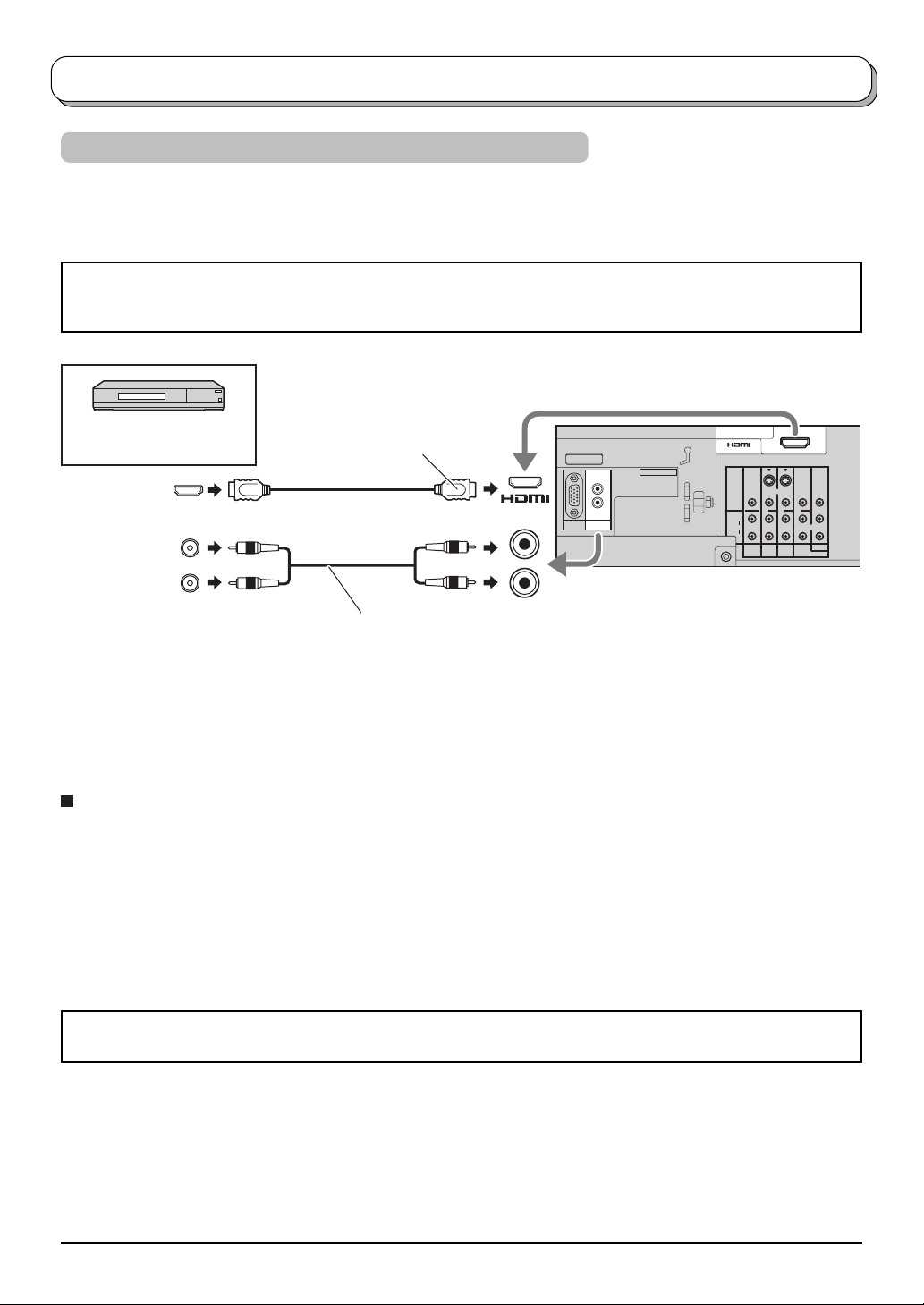
Audio / Video connections
How to connect the HDMI Input terminals
HDMI (High Definition Multi media Interface) is the first all-digital consumer electronics A/V interface that supports
uncompressed standard. The HDMI terminal supports both video and audio information.
An HDMI-compliant device*
connected to the HDMI input terminal.
• If the external device has DVI output only, use a DVI to HDMI adapter cable*
• Connect the audio cables to the AUDIO IN terminals when using a DVI to HDMI adapter cable.
• Select the audio setting in HDMI input. See page 18.
SET TOP BOX
DVD PLAYER
HDMI
OUT
L
AUDIO
OUT
R
Notes:
• This input terminal is not intended for use with computers.
• 720p/1080i signals will be re-formatted to view on your display.
• If the external devices have the aspect adjustment, set to 16:9.
• For applicable HDMI signals information see page 37.
1
such as a Set Top Box or DVD player with HDMI or DVI output terminal can be
2
to connect to the HDMI terminal.
Connect to HDMI AV IN terminal.
AV IN
U. S. patent No.4, 907, 093.
L
R
AUDIO
PC
IN
L
R
S VIDEO
AV IN
VIDEO
L
AUDIO
R
MONITOR
OUT
AUDIO IN
When using a DVI to HDMI adapter cable,
connect to AUDIO IN terminal.
MONO MONO MONO
AV1INAV2INAV4
Y
PB/C
B
PR/C
R
COMPONENT
IN
Compatible sampling frequency of AUDIO signal through HDMI (L.PCM) : 48 kHz / 44.1 kHz / 32 kHz
Notes:
• This HDMI connector is Type A.
• If you connect equipment without a digital output terminal, connect to the COMPONENT, S VIDEO or VIDEO input
terminal on the TV so you can receive an analogue signal.
• The HDMI IN terminal can only be used with 480i, 480p, 576i, 576p, 720p or 1080i picture signals. Set the Digital
Set Top Box DIGITAL OUT terminal output setting to 480i, 480p, 576i, 576p, 720p or 1080i. For detailed information,
refer to the Digital Set Top Box instruction manual. If you cannot display the picture because your Digital Set Top
Box does not have a DIGITAL OUT terminal output setting, use the component input (or the S Video input or
Video input). In this case the picture will be displayed as an analogue signal.
∗1. HDMI-compliant device is that has the HDMI Logo on it.
∗2. HDMI-DVI adapter cable: Consult your consumer electronics dealer for availability.
9
Audio / Video connections
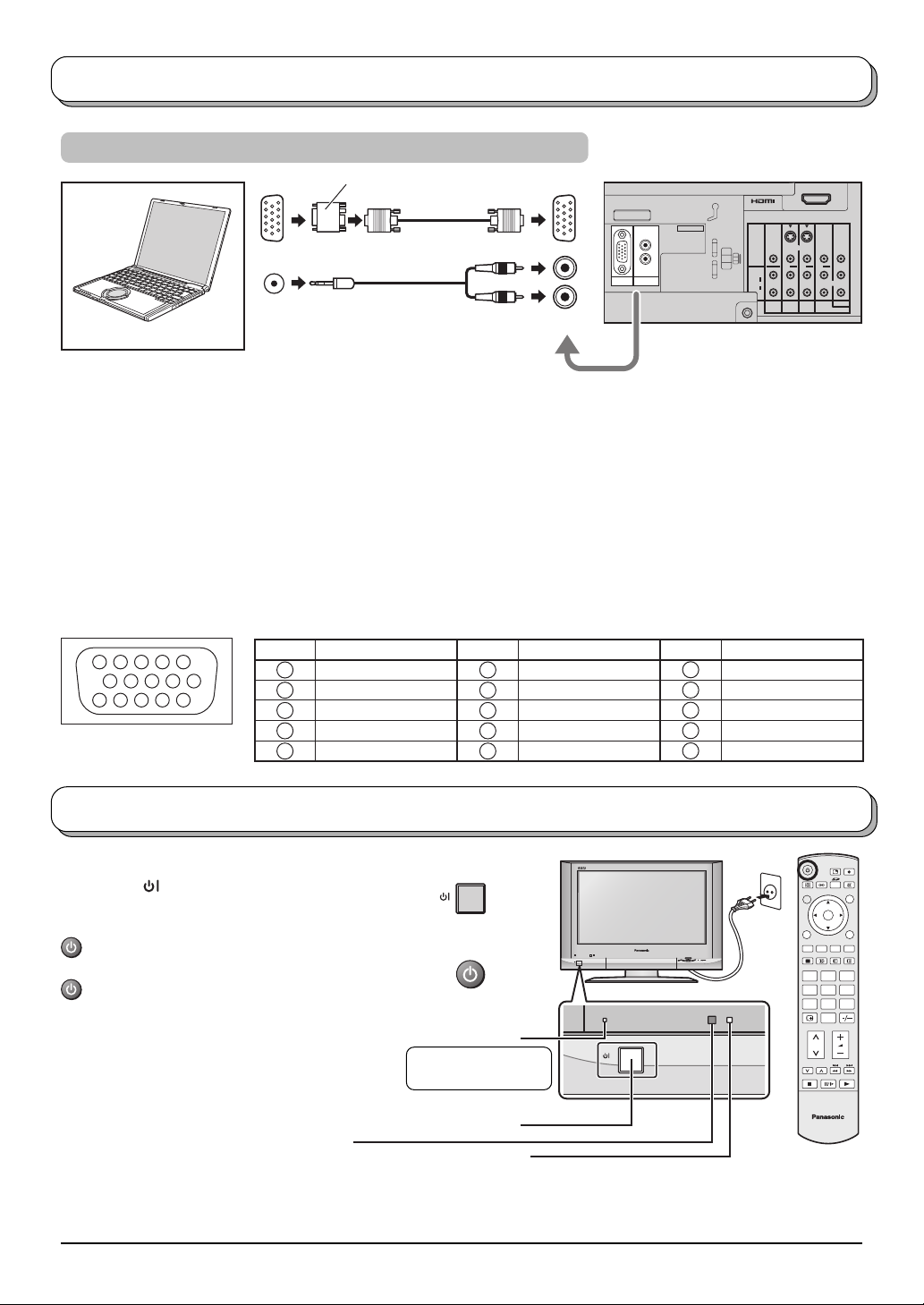
How to connect the PC Input terminals
Conversion adapter (if necessary)
RGB
U. S. patent No.4, 907, 093.
L
R
AUDIO
PC
IN
COMPUTER
AUDIO
(D-sub 15p)
(Stereo plug)
L
R
PC IN
AUDIO IN
Notes:
• Connect a cable which matches the audio output terminal on the computer.
Computer signals which can be input are those with a horizontal scanning frequency of 31 to 69 kHz and vertical
•
scanning frequency of 59 to 86 Hz. (However, the image will not be displayed properly if the signals exceed 1,024 lines.)
• When the aspect mode is set to “4:3”, maximum of 1,024 × 768 dots area of LCD panel is used for display, and
when the aspect mode is set to “16:9”, full area (1,366 × 768 dots) of LCD panel is used for display.
• Some PC models cannot be connected to the set.
• There is no need to use an adapter for computers with DOS/V compatible D-sub 15P terminal.
• The computer shown in the illustration is for example purposes only.
• Additional equipment and cables shown are not supplied with this set.
• Do not set the horizontal and vertical scanning frequencies for PC signals which are above or below the specified
frequency range.
• For applicable PC signals information see page 37.
Signal Names for D-sub 15P Connector
45
10
15 14 13 12 11
1
2
67839
Pin Layout for PC Input
Terminal
Pin No. Signal Name Pin No. Signal Name Pin No. Signal Name
1
2
3
4
NC (not connected)
5
GND (Ground)
R
G
B
6
7
8
9
10
GND (Ground)
GND (Ground)
GND (Ground)
NC (not connected)
GND (Ground)
11
12
13
14
15
AV IN
S VIDEO
VIDEO
MONO MONO MONO
L
AUDIO
R
MONITOR
AV1INAV2INAV4
OUT
Y
PB/C
PR/C
COMPONENT
IN
NC (not connected)
NC (not connected)
HD/SYNC
VD
NC (not connected)
B
R
Power On / Off
Connect the mains plug to the wall socket.
Press the [
set on.
To switch the TV set to Standby mode, press the
button on the remote control.
The TV set can be switched on by pressing the
button again if it was in Standby mode.
Note:
This TV will still consume some power
as long as the mains plug is still inserted
into the wall socket.
10
] switch on the TV set to turn the
Main POWER switch
Remote control signal sensor
Within about 23 feet (7 meters) in
front of the TV set.
OK
123
456
7
89
0
Power Indicator
Standby : Red
On : No Light
TV
C.A.T.S. sensor
LCD C.A.T.S. (Contrast Automatic Tracking System) automatically
senses the ambient light conditions and adjusts the brightness
and gradation accordingly, to optimize contrast.
C.A.T.S. is in effect when Menu mode (page 17) is set to Auto.
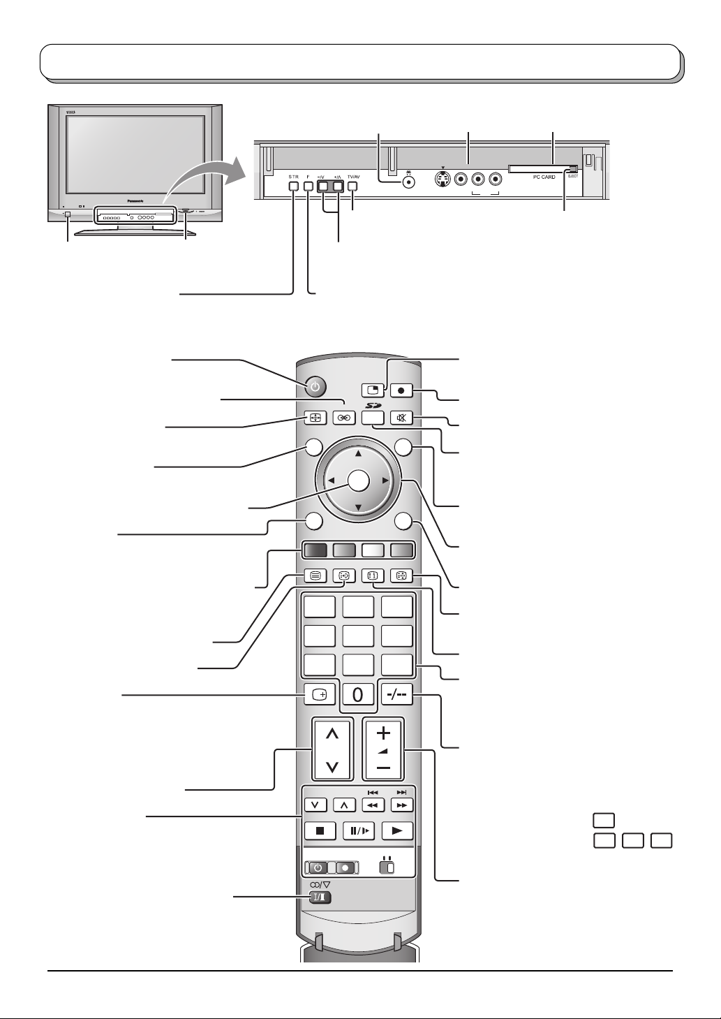
Basic controls: front panel and remote control
On / Off switch
SD CARD slot
(see page 24)
STR (Normalization store)
Used to store tuning and other function
settings.
Standby On / Off button
Switches TV On or Off (Standby mode).
Surround On / Off (see page 18)
Aspect control button
(see page 20)
N (Normalize) button
Resets all settings to their default levels.
Press to confirm selections and choices.
MENU button
Press to access the Picture, Sound and
Setup menus. (see page 17-19)
Coloured buttons used for the selection,
navigation and operation of various
functions.
Teletext button (see page 32-34)
Text F.P. button (see page 33)
Recall button
Press to display the current system status,
for example, Programme number, Channel
number, Stereo mode, Aspect mode,
Sound menu, Picture menu.
Channel up / down button
VCR / DVD buttons
(see page 34)
Headphone jack
(see page 7)
TV/AV button
(see page 7)
AV3 terminals
(see page 7)
AV3 IN
S VIDEO VIDEO L/MONO -
PC CARD slot
(see page 24)
R
AUDIO
PC CARD EJECT button
(see page 24)
Increases or decreases the programme position by one. When a function
is already displayed, press to increase or decrease the selected function.
When in Standby mode, switches TV On.
F (Function select)
Displays the On Screen Display functions, use repeatedly to select from the
available functions - Volume, Contrast, Brightness, Colour, Sharpness, Tint
(in NTSC mode), Bass, Treble, Balance and Tuning mode (for TV input only).
MULTI PIP button
(see page 21)
SD Record button (see page 26)
Sound mute On / Off
ASPECT
N
MULTIPIP
SURROUND
SD REC
TV/AV
SD button
Access Card operations.
MENU
OK
EXIT
(see page 24-31)
Switch between viewing TV or AV input.
(see page 7)
Cursor buttons to make selections and
TEXT
F.P. INDEX HOLD
adjustments.
Exit the mode.
123
456
Text Hold / Picture Still button
(see page 31, 32)
Text Index button (see page 34)
78
9
Programme / channel change buttons (0-9)
and Teletext page buttons.
(see page 32-34)
When in Standby mode, switches TV On.
Two digit button
You can select the numbers directly by
pressing Programme Number button and
the two digit Numbers by pressing “Two
Digit” and Programme Number buttons.
REC VCR D
Programme Number 8.....
Programme Number 12....
VD
8
-/--, 1, 2
Stereo / Bilingual Sound Selection
(see page 35)
Volume up / down button
11
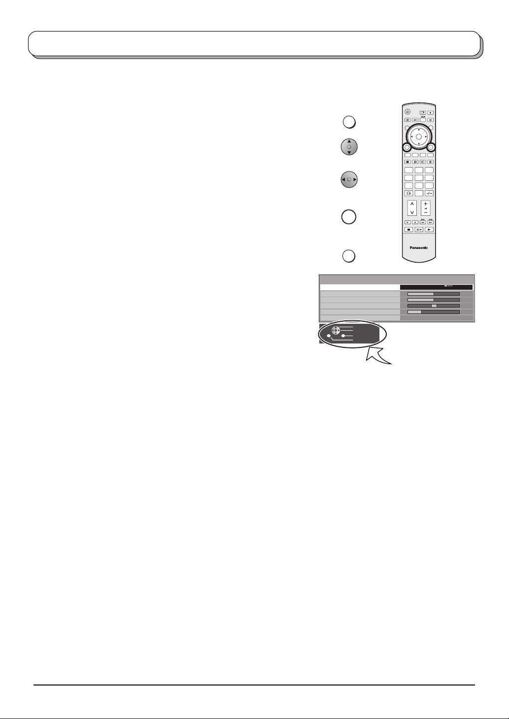
Using the On Screen Displays
Many features available on this TV can be accessed via the On Screen Display menu system. Use the remote
control as shown below to access and adjust features as desired.
The MENU button is used to open the main menus and
also to return to the previous menu.
The up and down cursor buttons are used to move the
cursor and select menus.
The left and right cursor buttons are used to access menus,
adjust levels or to select from a range of options.
The OK button is used with a number of features to store
settings after adjustments have been made or options have
been set.
The EXIT button is used to exit the menu system and return
to the normal viewing screen.
An On Screen Help box is displayed whenever a menu is
displayed on the TV. This Help box indicates which buttons on
the remote control are used to navigate the menu shown, see
above for descriptions of button functions.
Note:
The Help box is not shown in the menu pictures in this
instruction book due to space limitations.
MENU
OK
EXIT
Sound menu
Menu
Bass
Treble
Balance
Headphone volume
Surround
Select
Change
Exit
Return
OK
123
456
7
89
0
TV
Music
Off
ON SCREEN HELP
‘Instructions’ box
12
 Loading...