

TX-32LXD50
A
A
A
A
A
r
/
TX-26LXD50
TX-32LX50F
TX-32LX50P
TX-26LX50F
TX-26LX50P
LH41Chassis
ORDERNO.PCZ0503030C2
WideLCDTV
Specifications
PowerSource
PowerConsumption
LCD WideXGA(1,366×768pixels)
ScreenSize 575.8mm(W)×323.7mm(H)(TX-26LXD50,TX-26LX50F/P)
Sound
Speake
AudioOutput 20W(5.4W+5.4W,4.6W+4.6W)
Headphones M3(3.5mm)Jack×1
Scanningformat 480i(60Hz),480p(60Hz),576i(50Hz),576p(50Hz),720p(50Hz),1080i(50Hz)
ReceivingSystems
Bandname DVB(TX-26LXD50/32LXD50) DigitalterrestrialservicesviaUHFaerialinput.
C220-240V,50/60Hz
verageuse:133W(0.78A)(TX-26LXD50)
verageuse:169W(0.98A)(TX-32LXD50)
Standbycondition:
0 1W(WithoutDVBTimerprogrammes)
11W(WithDVBTimerprogrammes)
verageuse:126W(TX-26LX50F/P)
verageuse:161W(TX-32LX50F/P)
Standbycondition:0.4W
16:9aspectratioLCDpanel
697.7mm(W)×392.3mm(H)(TX-32LXD50,TX-32LX50F/P)
WooferØ8cm×2pcs,FullrangeØ5cm×2pcs
PALI(TX-26LXD50/32LXD50) UHFE21-68.
PALB,G,H,SECAMB,GSECAML/L’(TX-26LX50F/P,TX-32LX50F/P)
VHFE2-E12 VHFH1-H2(ITALY)
VHFA-H(ITALY) UHFE21-E69
CATV(S01-S05) CATVS1-S10(M1-M10)
w 2005MatsushitaElectricIndustrialCo.,Ltd.All
rightsreserved.Unauthorizedcopyingand
distributionisaviolationoflaw.
r
V
V
TX-32LXD50/TX-26LXD50/TX-32LX50F/TX-32LX50P/TX-26LX50F/TX-26LX50P
CATVS11-S20(U1-U10) CATVS21-S41(Hyperband)
PALD,K,SECAMD,K(TX-26LX50F/P,TX-32LX50F/P)
VHFR1-R2 VHFR3-R5
VHFR6-R12 UHFE21-E69
PAL525/60 PlaybackofNTSCtapefromsomePALVideorecord
M.NTSC PlaybackfromM.NTSCVideorecorders(VCR)
NTSC(AVinputonly) PlaybackfromNTSCVideorecorders(VCR)
Aerial-Rea
OperatingConditions Temperature:5°C-35°C
ConnectionTerminals
AV1(Scartconnecter) 21Pinterminal(Audio/Videoin,Audio/Videoout,RGBin)
AV2(Scartconnecter) 21Pinterminal(Audio/Videoin,Audio/Videoout,S-Videoin,Q-Link)
AV3
IDEO RCAPINType×1
S-VIDEO MiniDIN4-pin
AUDIOL-R RCAPINType×2
AV4(Scartconnecter) 21Pinterminal(Audio/Videoin,Audio/Videoout,RGBin,S-Videoin,Q-Link)
COMPONENT
IDEO Y,PB,PR
AUDIOL-R RCAPINType×2
Output
AUDIOL-R RCAPINType×2
Dimensions(W×H×D)
IncludingTVStand 663mm×556mm×299.5mm(TX-26LXD50,TX-26LX50F/P)
TVSetOnly 663mm×494.3mm×140.7mm(TX-26LXD50,TX-26LX50F/P)
Mass(Weight) 18kgNet(TX-26LXD50,TX-26LX50F/P)
UHF(TX-26/32LXD50)UHF/VHF(TX-26/32LX50F/P)
Humidity:5%-90%RH(non-condensing)
795mm×634.7mm×299.5mm(TX-32LXD50,TX-32LX50F/P)
795mm×573mm×140.7mm(TX-32LXD50,TX-32LX50F/P)
21kgNet(TX-32LXD50,TX-32LX50F/P)
ers(VCR)
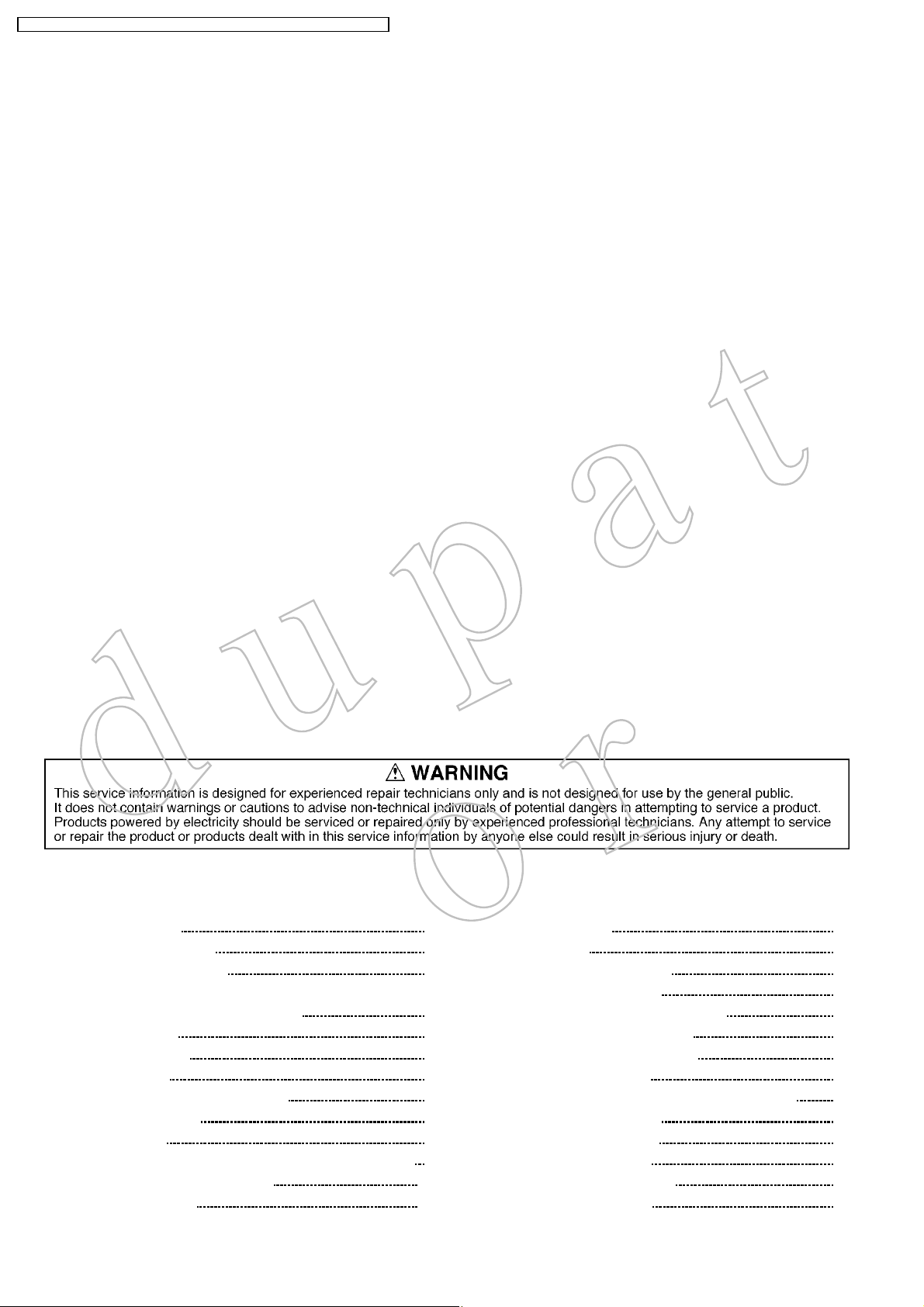
CONTENTS
1 SafetyPrecautions 4
2 PreventionofElectroStaticDischarge(ESD)to
ElectrostaticallySensitive(ES)Devices 5
3 Applicablesignals 5
4 SelfCheckFunction 6
5 ChassisBoardLayout 8
6 Beforeservicing 9
Page Page
1.1. GeneralGuidelines 4
1.2. Touch-CurrentCheck 4
4.1. SelfCheck 6
4.2. PowerLEDBlinkingtimingchart 7
6.1. Kindandlocationoftheflexiblecableandbridgecable 9
6.2. Howtoremovetheconnector 10
6.3. Wiredressing1 11
6.4. Wiredressing2 12
7 Servicingmethod 13
7.1. Removingthestandass y 13
7.2. Removingtherearcover 13
7.3. RemovingthespeakerboxLandR 13
7.4. RemovingtherearAVbracket 14
7.5. Removingtherearmetalframe 14
7.6. RemovingtheP-Board 14
7.7. RemovingtheXV-Board(ForLXD50modelonly) 14
7.8. RemovingtheDG-Board 15
7.9. RemovingtheAP-Board 15
7.10. RemovingtheH-Board 15
7.11. RemovingG-Boardbracket 15
7.12. RemovingtheG-Board 16
2

TX-32LXD50/TX-26LXD50/TX-32LX50F/TX-32LX50P/TX-26LX50F/TX-26LX50P
7.13. RemovingtheK-Board 16
7.14. RemovingtheV-Board 16
7.15. Removingthemainchassis 16
7.16. RemovingtheLCDpanel 17
8 ServiceModeFunction 18
8.1. HowtoenterSERVICE1 18
8.2. HowtoenterSERVICE2 18
8.3. OptionDescription 21
8.4. OptionCodeSetting 23
9 Adjustmentmethod 24
9.1. WhiteBalanceAdjustment 24
10 BlockDiagram 25
10.1. Signal(1/3)BlockDiagram 25
10.2. Signal(2/3)BlockDiagram 26
10.3. Signal(3/3)BlockDiagram 27
10.4. Power(1/3)BlockDiagram 28
10.5. Power(2/3)BlockDiagram 29
10.6. Power(3/3)BlockDiagram 30
11 SchematicDiagram 31
11.1. SchematicDiagramNotes 31
11.2. AP-Board(1/2)andK-BoardSchematicDiagram 32
11.3. AP-Board(2/2)SchematicDiagram 33
11.4. XV-Board(1/5)SchematicDiagram 34
11.5. XV-Board(2/5)SchematicDiagram 35
11.6. XV-Board(3/5)SchematicDiagram 36
11.7. XV-Board(4/5)SchematicDiagram 37
11.8. XV-Board(5/5)SchematicDiagram 38
11.9. H-Board(1/3)SchematicDIagram 39
11.10. H-Board(2/3)SchematicDiagram 40
11.11. H-Board(3/3)SchematicDiagram 41
11.12. DG-Board(1/6)SchematicDiagram 42
11.13. DG-Board(2/6)SchematicDiagram 43
11.14. DG-Board(3/6)SchematicDiagram 44
11.15. DG-Board(4/6)SchematicDiagram 45
11.16. DG-Board(5/6)SchematicDiagram 46
11.17. DG-Board(6/6)SchematicDiagram 47
11.18. G-BoardandV-BoardSchematicDiagram 48
12 PrintedCircuitBoard 49
12.1. AP-Board 49
12.2. XV-Board(TX-26/32LXD50only) 51
12.3. H-Board 53
12.4. DG-Board 56
12.5. G-Board 59
12.6. K-BoardandV-Board 60
13 ExplodedViewandReplacementPartsList. 61
13.1. SetLayout 61
13.2. FrontChassisLayout 62
13.3. PackingExplodedView 63
13.4. MechanicalReplacementPartsList 64
14 ElectricalReplacementPartsList 66
14.1. ElectricalReplacementPartsListNotes 66
14.2. ElectricalReplacementPartsList(TX-32/26LXD50) 67
14.3. ElectricalReplacementPartsList(TX-32/26LX50F/P) 85
3

TX-32LXD50/TX-26LXD50/TX-32LX50F/TX-32LX50P/TX-26LX50F/TX-26LX50P
1 SafetyPrecautions
1.1. GeneralGuidelines
1. Whenservicing,observetheoriginalleaddress.Ifashortcircuitisfound,replaceallpartswhichhavebeenoverheatedor
damagedbytheshortcircuit.
2. Afterservicing,seetoitthatalltheprotectivedevicessuchasinsulationbarriers,insulationpapersshieldsareproperly
installed.
3. Afterservicing,makethefollowingleakagecurrentcheckstopreventthecustomerfrombeingexposedtoshockhazards.
1.2. Touch-CurrentCheck
1. PlugtheACcorddirectlyintotheACoutlet.Donotuseanisolationtransformerforthischeck.
2. Connectameasuringnetworkfortouchcurrentsbetweeneachexposedmetallicpartonthesetandagoodearthgroundsuch
asawaterpipe,asshowninFigure1.
3. UseLeakageCurrentTester(Simpson228orequivalent)tomeasurethepotentialacrossthemeasuringnetwork.
4. Checkeachexposedmetallicpart,andmeasurethevoltageateachpoint.
5. ReservetheACplugintheACoutletandrepeateachoftheabovemeasure.
6. Thepotentialatanypoint(TOUGHCURRENT)expressedasvoltageU1andU2,doesnotexceedthefollowingvalues:
Fora.c.:U1=35V(peak)andU2=0.35V(peak);
Ford.c.:U1=1.0V,
Note:
ThelimitvalueofU2=0.35V(peak)fora.c.andU1=1.0Vford.c.correspondtothevalues0 7mA(peak)a.c.and2.0
mAd.c.
ThelimitvalueU1=35V(peak)fora.c.correspondtothevalue70mA(peak)a.c.forfrequenciesgreaterthan100kHz.
7. Incaseameasurementisoutofthelimitsspecified,thereisapossibilityofashockhazard,andtheequipmentshouldbe
repairedandrecheckedbeforeitisreturnedtothecustomer.
Figure1
4

TX-32LXD50/TX-26LXD50/TX-32LX50F/TX-32LX50P/TX-26LX50F/TX-26LX50P
2 PreventionofElectroStaticDischarge(ESD)to
ElectrostaticallySensitive(ES)Devices
Somesemiconductor(solidstate)devicescanbedamagedeasilybystaticelectricity.Suchcomponentscommonlyarecalled
ElectrostaticallySensitive(ES)Devices.ExamplesoftypicalESdevicesareintegratedcircuitsandsomefield-effecttransistorsand
semiconductor"chip"components.Thefollowingtechniquesshouldbeusedtohelpreducetheincidenceofcomponentdamage
causedbyelectrostaticdischarge(ESD).
1. Immediatelybeforehandlinganysemiconductorcomponentorsemiconductor-equippedassembly,drainoffanyESDonyour
bodybytouchingaknownearthground.Alternatively,obtainandwearacommerciallyavailabledischargingESDwriststrap,
whichshouldberemovedforpotentialshockreasonspriortoapplyingpowertotheunitundertest.
2. AfterremovinganelectricalassemblyequippedwithESdevices,placetheassemblyonaconductivesurfacesuchasalminum
foil,topreventelectrostaticchargebuilduporexposureoftheassembly.
3. Useonlyagrounded-tipsolderingirontosolderorunsolderESdevices.
4. Useonlyananti-staticsolderremovaldevice.Somesolderremovaldevicesnotclassifiedas"anti-static(ESDprotected)"can
generateelectricalchargesufficienttodamageESdevices.
5. Donotusefreon-propelledchemicals.ThesecangenerateelectricalchargessufficienttodamageESdevices.
6. DonotremoveareplacementESdevicefromitsprotectivepackageuntilimmediatelybeforeyouarereadytoinstallit.(Most
replacementESdevicesarepackagedwithleadselectricallyshortedtogetherbyconductivefoam,alminumfoilorcomparable
conductivematerial).
7. ImmediatelybeforeremovingtheprotectivematerialfromtheleadsofareplacementESdevice,touchtheprotectivematerial
tothechassisorcircuitassemblyintowhichthedevicewillbeinstalled.
Caution
Besurenopowerisappliedtothechassisorcircuit,andobserveallothersafetyprecautions.
8. MinimizebodilymotionswhenhandlingunpackagedreplacementESdevices.(Otherwisehamlessmotionsuchasthebrushing
togetherofyourclothesfabricortheliftingofyourfootfromacarpetedfloorcangeneratestaticelectricity(ESD)sufficientto
damageanESdevice).
3 Applicablesignals
ApplicableinputsignalforComponent(Y,PB,PR)
Note:
Signalswithoutabovespecificationmaynotbedisplayedproperly.
5
TX-32LXD50/TX-26LXD50/TX-32LX50F/TX-32LX50P/TX-26LX50F/TX-26LX50P
4 SelfCheckFunction
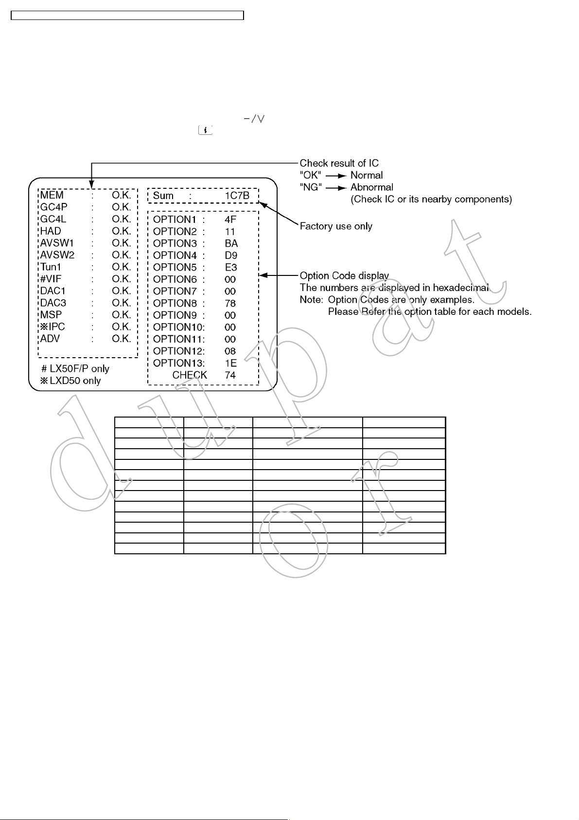
4.1. SelfCheck
1. Self-CheckisusedtoautomaticallycheckthebuslinesandhexadecimalcodeoftheTVset.
2. TogetintotheSelf-Checkmodepressthe Down ( )buttononthecustomercontrolsatthefrontoftheset,atthesame
timepressingthe Status/Information( ) buttonontheremotecontrol,andthescreenwillshow:
3. TurnofftheTVtoresetJPEGViewercircuitafterSELF-CHECK.
IftheCCUportshavebeencheckedandfoundtobeincorrectornotlocatedthen“--”willappearinplaceof“O.K.”.
Display Ref.No. Description P.C.B.
MEM IC1107 Memory DG-Board
GC4P IC4054 GlobalCore DG-Board
GC4L IC4057 GlobalCore DG-Board
HAD IC4012 OSDRGBA/DConverter DG-Board
AVSW1 IC3005 AVSwitchVIDEO H-Board
AVSW2 IC2105 AVSwitchAUDIO H-Board
Tun1 TU3201 Tuner H-Board
DAC1 IC1106 DACcontrol1 DG-Board
DAC3 IC3006 DACcontrol3 H-Board
MSP IC2106 StereoDecoder H-Board
IPC IC8013 HDSLPEAKSLite XV-Board
ADV IC4005 A/DConverter DG-Board
6
TX-32LXD50/TX-26LXD50/TX-32LX50F/TX-32LX50P/TX-26LX50F/TX-26LX50P
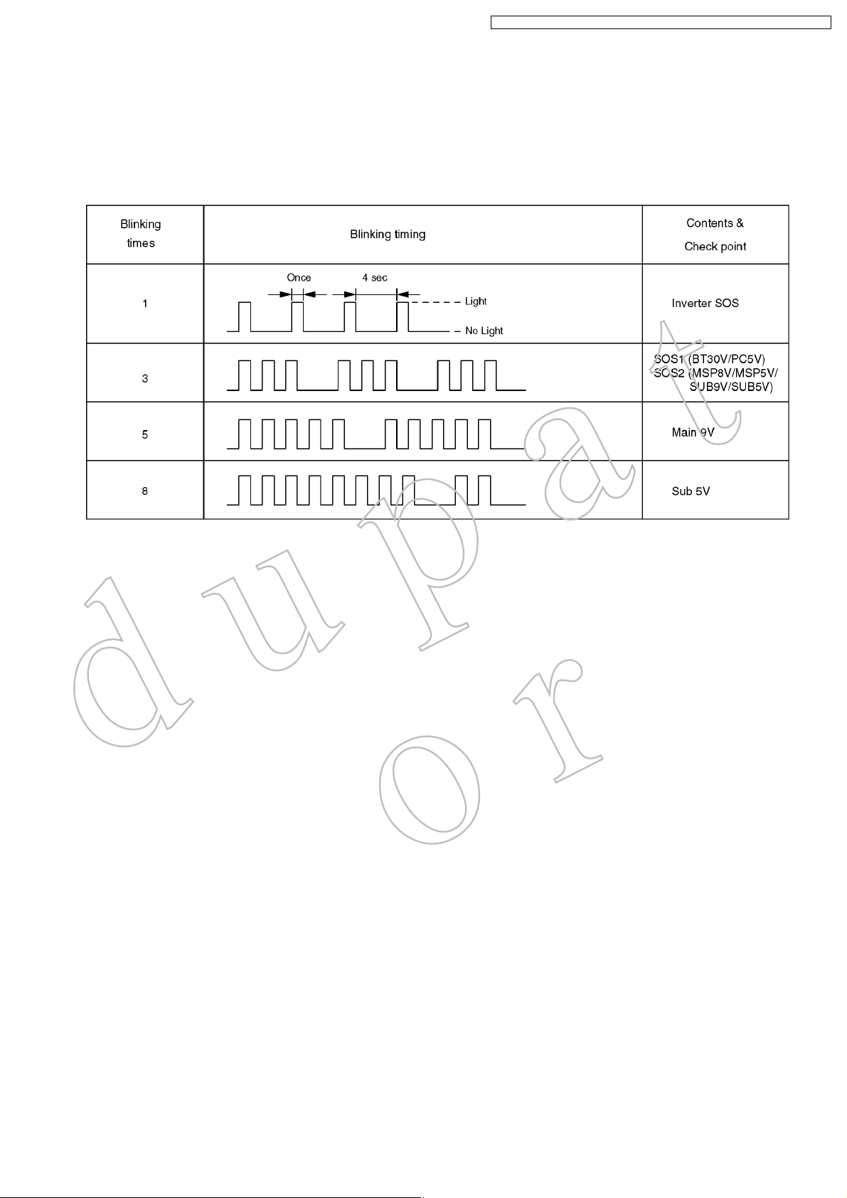
4.2. PowerLEDBlinkingtimingchart
1. Subject
InformationofLEDFlashingtimingchart.
2. Contents
Whenanabonormalityhasoccurredtheunit,theprotectioncircuitoperatesandresettothestandbymode.Atthistime,the
defectiveblockcanbeidentifiedbythenumberofblinkingofthePowerLEDonthefrontpaneloftheunit.
7
TX-32LXD50/TX-26LXD50/TX-32LX50F/TX-32LX50P/TX-26LX50F/TX-26LX50P
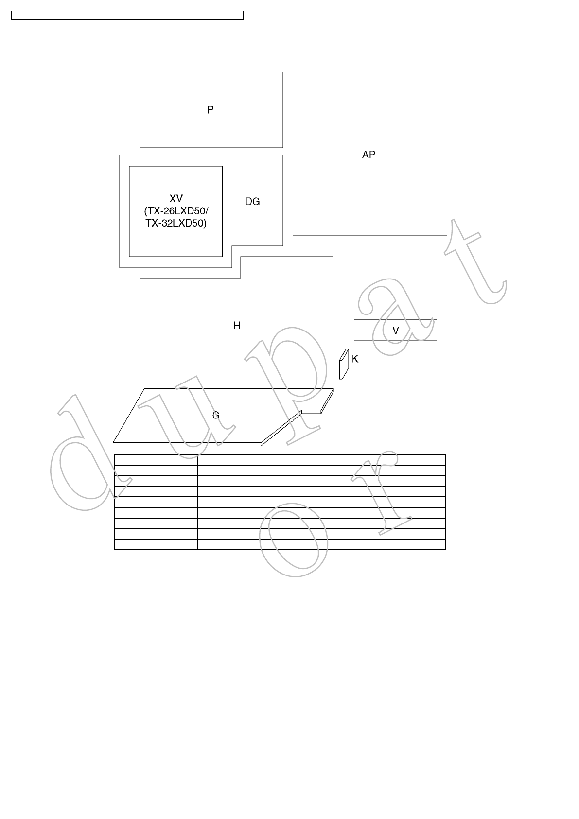
5 ChassisBoardLayout
BoardName Function
AP-Board Regulator
DG-Board GlobalCore,A/DConverter,MCU
H-Board AVconnector,TVTuner,AVSwitch
K-Board PowerSwitch
G-Board FrontAV&HPconnector,KeySwitch
P-Board DCPowerSupply
V-Board RemoteReceiver,LED
XV-Board DVBTuner
8
TX-32LXD50/TX-26LXD50/TX-32LX50F/TX-32LX50P/TX-26LX50F/TX-26LX50P
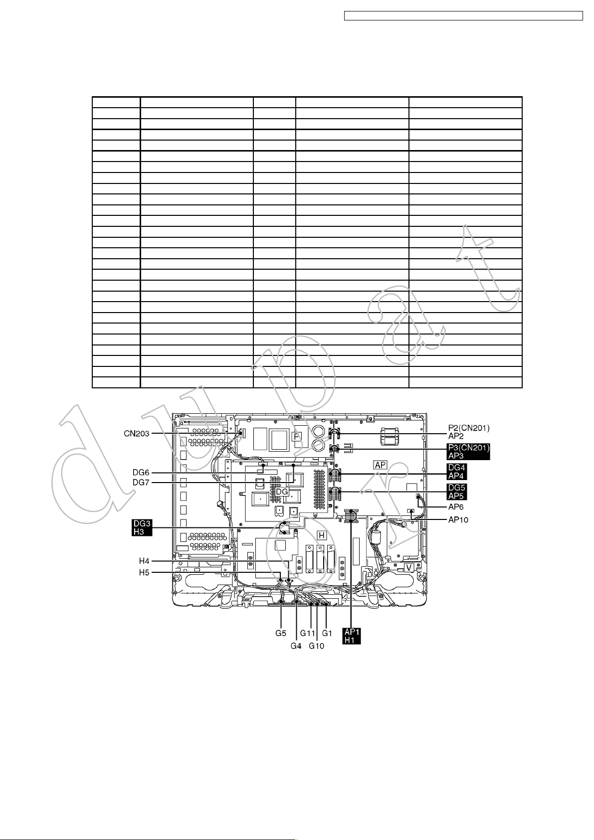
6 Beforeservicing
6.1. Kindandlocationoftheflexiblecableandbridgecable
RefNo. Connectertype Pins Location OppositeRefNo.
G1 - 10pin G-Board V1
G4 - 30pin G-Board H4
G5 - 20pin G-Board H5
G10 - 4pin G-Board speakerboxL
G11 - 5pin G-Board speakerboxR
AP1 BridgeType 23pin AP-Board H1
AP2 - 7pin AP-Board P5(CN101)
AP3 BridgeType 11pin AP-Board P3
AP4 BridgeType 22pin AP-Board DG4
AP5 BridgeType 22pin AP-Board DG5
AP6 - 3pin AP-Board K6
DG3 Flexibletype 40pin DG-Board H3
DG4 Bridgetype 23pin DG-Board AP4
DG5 Bridgetype 23pin DG-Board AP5
DG6 - 8pin DG-Board LCDPanel
DG7 - 32pin DG-Board LCDPanel
H1 Bridgetype 23pin H-Board AP1
H4 - 30pin H-Board G4
H5 - 20pin H-Board G5
H3 Flexibletype 40pin H-Board DG3
AP10 - 2pin AP-Board ACcord
K6 - 3pin K-Board AP6
P1(CN203) - 8pin P-Board CN1(Inverter)
P2(CN101) - 7p n P-Board AP2
P3(CN201) BridgeType 11pin P-Board AP3
V1 - 10pin V-Board G1
9
TX-32LXD50/TX-26LXD50/TX-32LX50F/TX-32LX50P/TX-26LX50F/TX-26LX50P
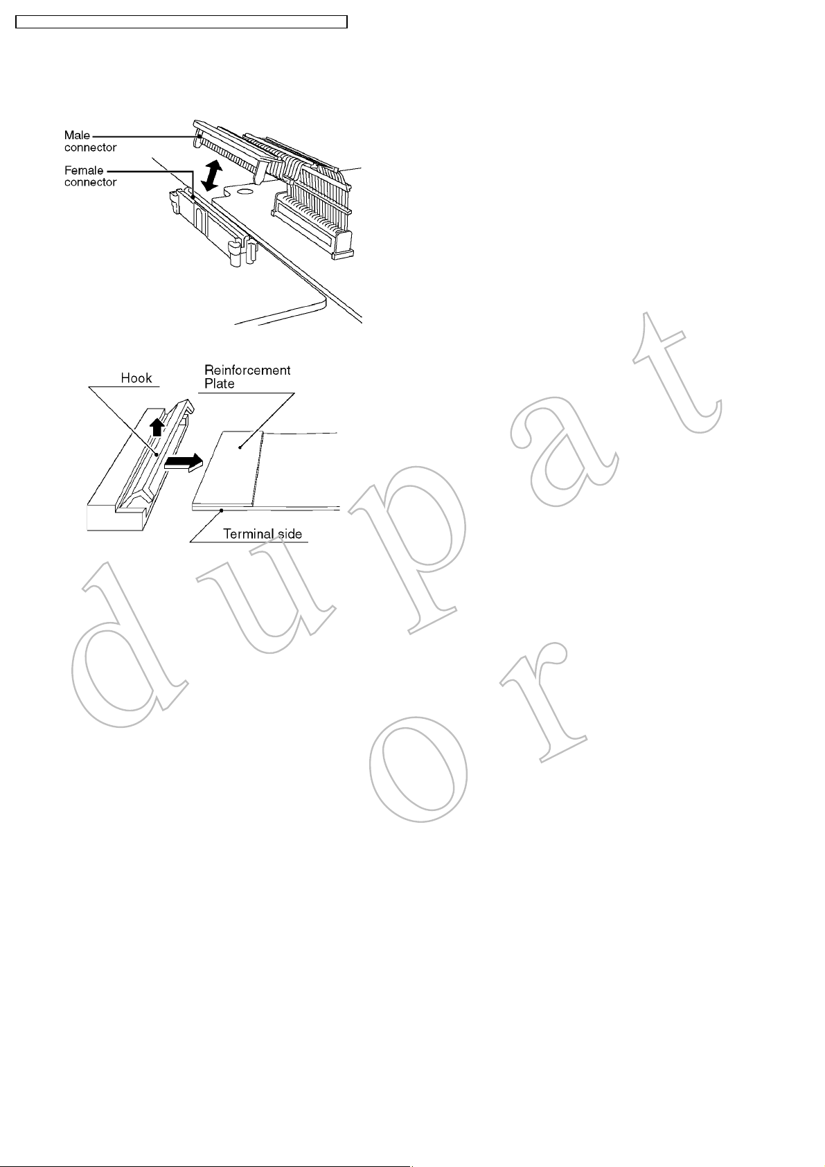
6.2. Howtoremovetheconnector
Bridgecableconnector
Flexiblecableconnector
10
TX-32LXD50/TX-26LXD50/TX-32LX50F/TX-32LX50P/TX-26LX50F/TX-26LX50P
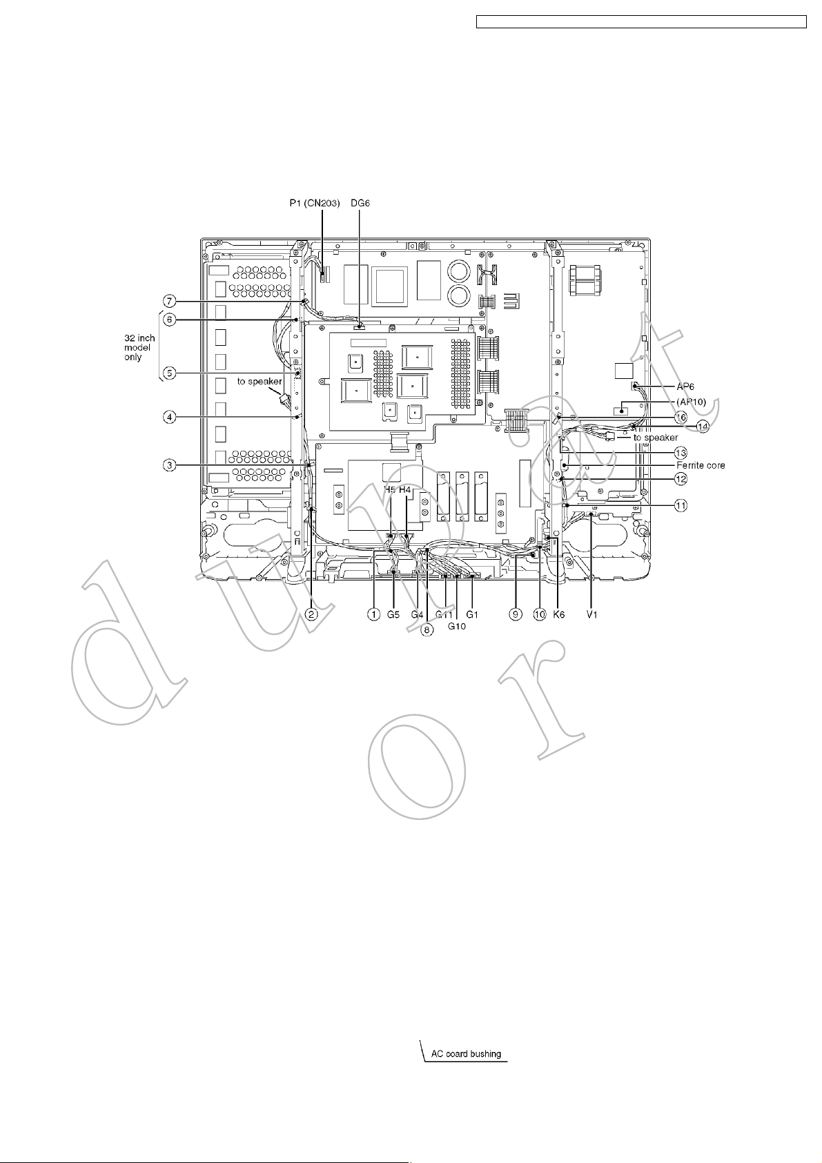
6.3. Wiredressing1
1. Putaferritecore(JOKF00000018)totheAP6-K6(PowerSwitch)connectingwireasillustratedbelow.
2. Putaferritecore(JOKG00000054)tothepowercordasillustratedbelow.
3. Makethewiredressingasillustratedbelow.
11
TX-32LXD50/TX-26LXD50/TX-32LX50F/TX-32LX50P/TX-26LX50F/TX-26LX50P
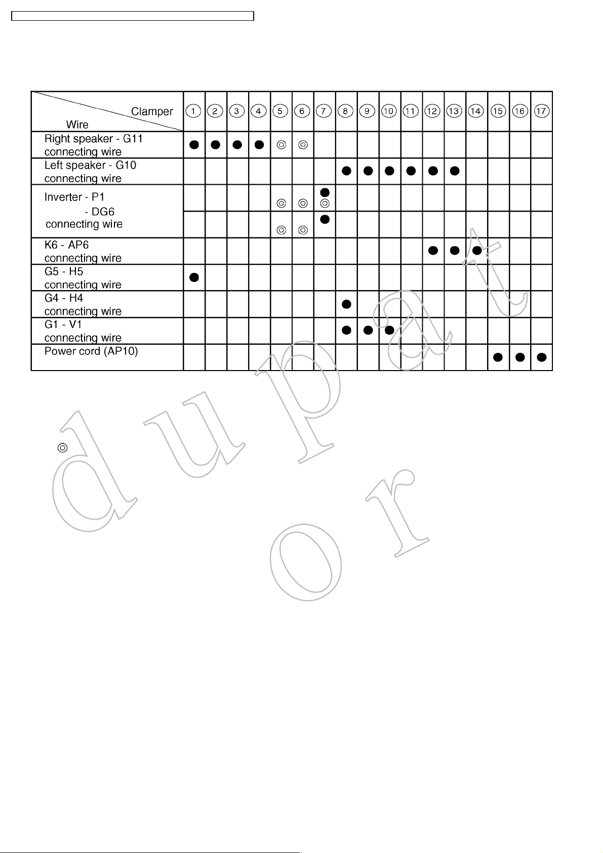
6.4. Wiredressing2
<Clamping>
Notes:
1. Connecteveryconnectorsurely.
2. Managewiresnottotouchanysharpedgeofthemetalparts.
3. Managewiresnottohavetoomuchtension.
4. :for32inchmodelonly.
12
7 Servicingmethod
TX-32LXD50/TX-26LXD50/TX-32LX50F/TX-32LX50P/TX-26LX50F/TX-26LX50P
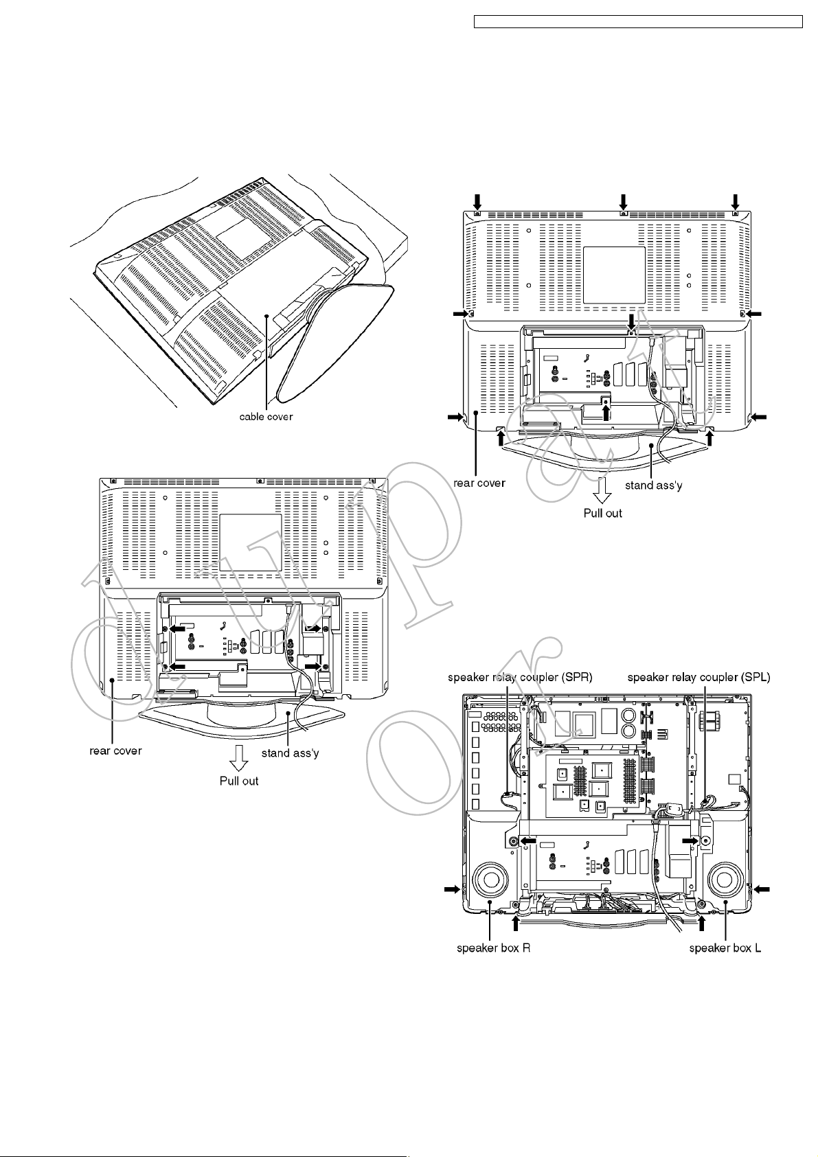
7.1. Removingthestandass´y
1. Laydownthemainunitsothattherearcoverfacesupward.
2. Removethecablecover.
3. Removethefixingscrews(4pcs).
4. Removethestandass´y.
7.2. Removingtherearcover
1. Removethestandass´y.(See7.1.)
2. Removethefixingscrews(11pcs).
3. Removetherearcover.
7.3. RemovingthespeakerboxL
andR
1. Removetherearcover.(See7.2.)
2. Disconnectthespeakerrelaycouplers(SPLandSPR).
3. Removethefixingscrews(6pcs).
4. RemovethespeakerboxLandR.
13

TX-32LXD50/TX-26LXD50/TX-32LX50F/TX-32LX50P/TX-26LX50F/TX-26LX50P
7.4. RemovingtherearAVbracket
1. Removetherearcover(See7.2.)andthespeakerboxL
andR.(See7.3.)
2. ReleasetheACcordfromtherearAVbracketandclamper
ontherearmetalframe,andremovetheACcord.(the
couplerAP10)
3. Removethefixingscrews(3pcs).
4. RemovetherearAVbracketass´y.
7.6. RemovingtheP-Board
1. Removetherearcover.(See7.2.)
2. DisconnectthecouplersP2(CN101),P3(CN201)andP1
(CN203).
3. Removethefixingscrew(4pcs).
4. RemovetheP-Board.
7.5. Removingtherearmetalframe
1. RemovetherearAVbracket.(See7 4.)
2. Releasethecablesfromtheclampersontherearmetal
frames.
3. Removethefixingscrews(4pcs).
4. Removetherearmetalframes(rightandleft).
7.7. RemovingtheXV-Board(For
LXD50modelonly)
1. RemovetherearAVbracket(See7.4.)andtherearmetal
frame.(See7.5.)
2. Disconnectthecouplerscarefully(XV22andDG22).
3. Removethefixingscrews(5pcs).
4. RemovetheXV-Boardunit.
5. Removethescrews(×5 )
6. RemovetheXV-Board.
14

TX-32LXD50/TX-26LXD50/TX-32LX50F/TX-32LX50P/TX-26LX50F/TX-26LX50P
7.8. RemovingtheDG-Board
1. RemovetherearAVbracket(See7.4.)andtherearmetal
frame.(See7.5.)
2. Disconnectthecouplers(DG6andDG7),theflexiblecable
(DG3)andthebridgecables(DG4andDG5).
3. Removethefixingscrews(6pcs).
4. RemovetheDG-Board.
7.10. RemovingtheH-Board
1. RemovetherearAVbracket(See7.4.)(andtherearmetal
frame).(See7.5.)
2. Disconnecttheflexiblecable(H3),thebridgecable(H1)
andthecouplers(H4andH5).
3. Removethefixingscrews(4pcs).
4. RemovetheH-Board.
7.9. RemovingtheAP-Board
1. RemovetherearAVbracketass´y(See6.4.)andtherear
metalframe.(See6 5.)
2. Disconnectthecouplers(AP2,AP6andAP10(ACCord))
andthebridgecables(H1(AP1)ontheH-Board,P3/CN201
(AP3)ontheP-BoardandDG4(AP4)andDG5(AP5)on
theDG Board.
3. Removethefixingscrews(7pcs).
4. RemovetheAP-Board.
7.11. RemovingG-Boardbracket
1. RemovetherearAVbracket(See7.4.).
2. Disconnectthecouplers(G1,G4,G5,G10andG11).
3. RemoveascrewontheDG-Boardandreleasetheearth
lugfromtheG-Board.
4. ReleasethecablesfromthecableholdersoftheG-Board
bracket.
5. Removethefixingscrews(2pcs).
6. RemovetheG-Boardbracket(withtheG-Board).
15
TX-32LXD50/TX-26LXD50/TX-32LX50F/TX-32LX50P/TX-26LX50F/TX-26LX50P
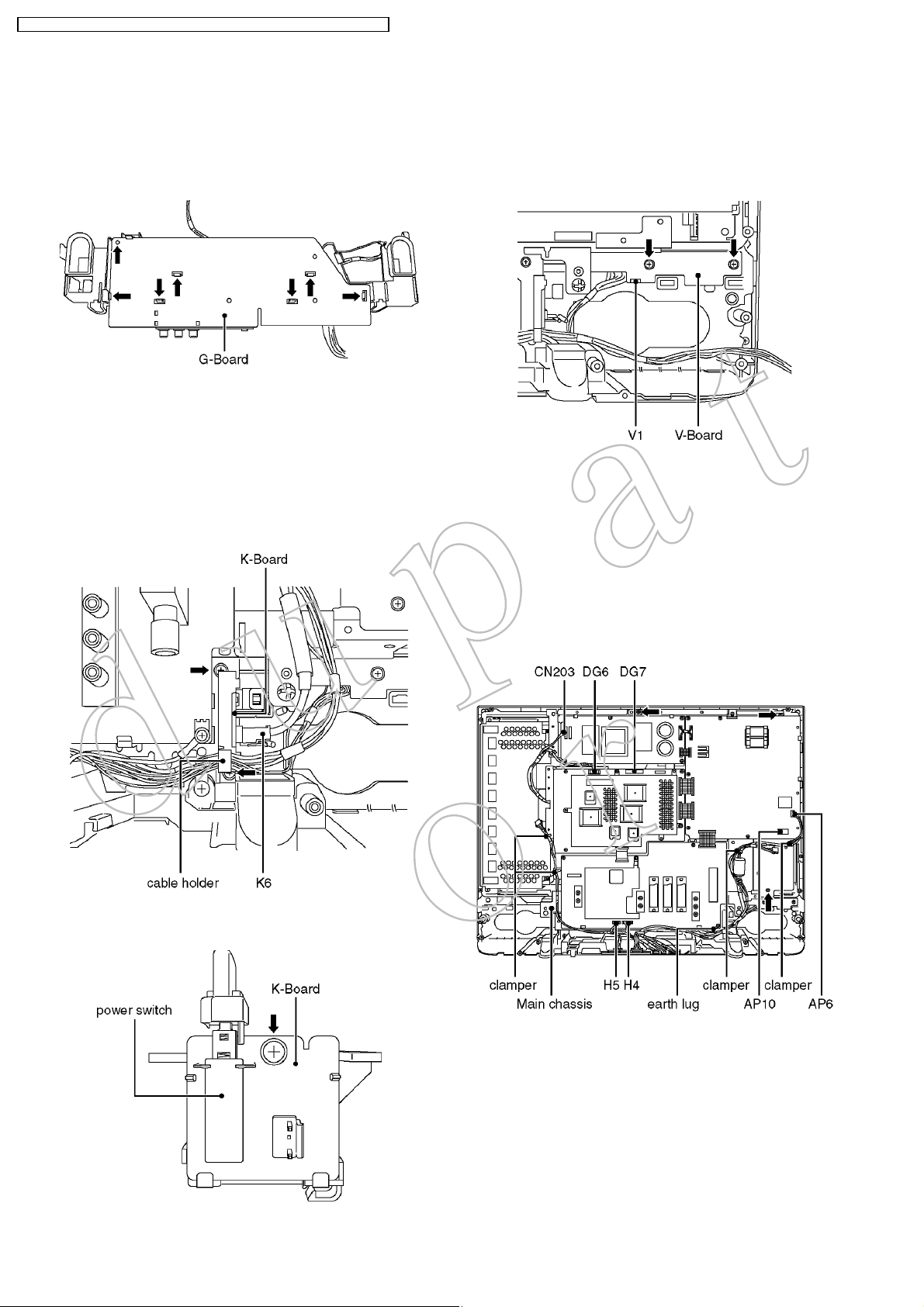
7.12. RemovingtheG-Board
1. RemovetheG-Boardbracket.(See7.10.)
2. Pushthehooks(7points)toreleasetheG-Boardfromthe
G-Boardbrackets.
3. RemovetheG-Board.
7.13. RemovingtheK-Board
1. RemovetherearAVbracket(See7.4.)andtherearmetal
frame(right).(See7.5.)
2. Removeacoupler(K6)andreleasethecablesfromholder
ontheK-Boardbracket.
3. Removethescrews(2pcs).
4. RemovetheK-BoardbracketwiththeK-board.
7.14. RemovingtheV-Board
1. Removetherearcover.(See7.2.)
2. Removethescrews(2pcs).
3. RemovetheV-Board.
4. Disconnectthecoupler(V1).
7.15. Removingthemainchassis
1. RemovetherearAVbracket(See7.4.)andtherearmetal
frame.(See7.5.)
2. Disconnectthecouplers(CN203,DG6,DG7,H4,H5,AP6,
AP10)andtheearthlug(ontheH-Board)fromG-Board.
3. Releasethecablesfromtheclampersonthemainchassis.
4. Removethefixingscrews(3pcs).
5. RemovethemainchassiswiththeP-Board,theAP-Board,
theDG-BoardandtheH-Board.
5. Removeascrew.
6. RemovetheK-Board.
16
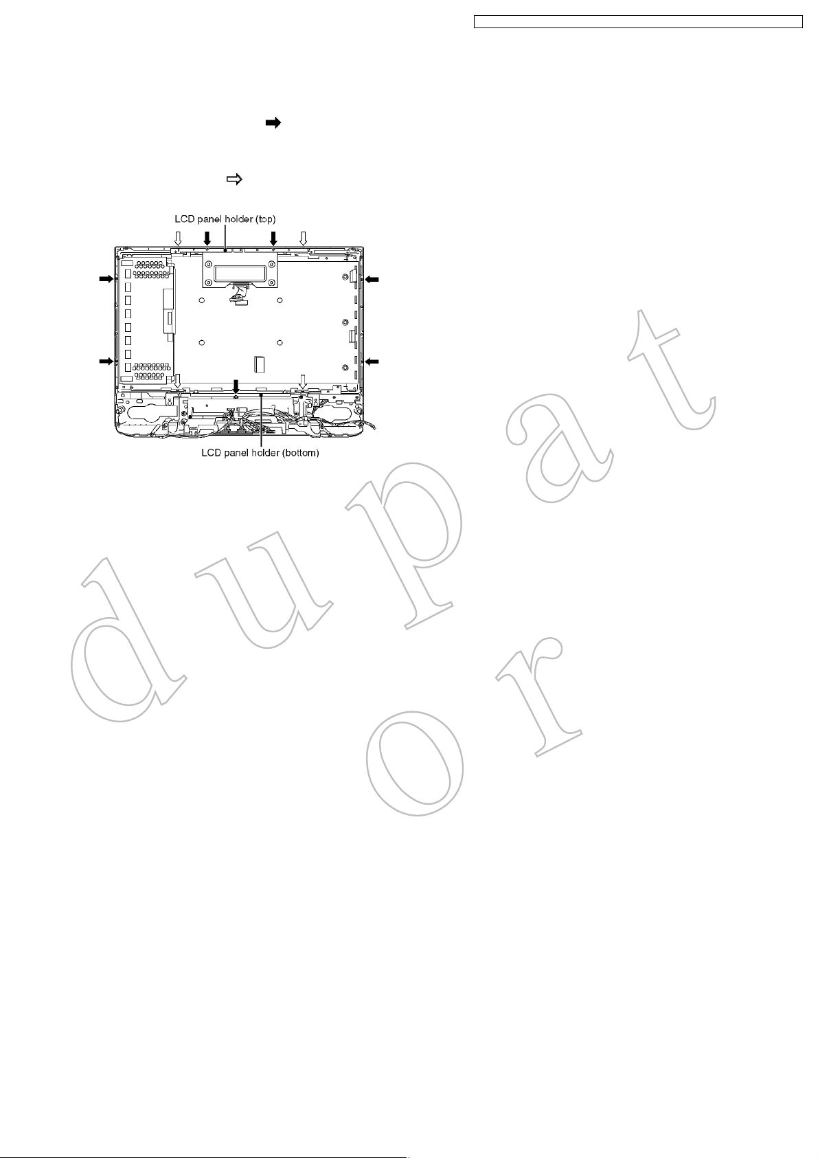
7.16. RemovingtheLCDpanel
1. Removethemainchassis.(See7.15.)
2. Removethefixingscrews(7pcs ).
3. RemovetheLCDpanelandLCDpanelholders(rightand
left).
4. Removethescrew(4pcs ).
5. RemovetheLCDpanelholders(topandbottom).
TX-32LXD50/TX-26LXD50/TX-32LX50F/TX-32LX50P/TX-26LX50F/TX-26LX50P
17

TX-32LXD50/TX-26LXD50/TX-32LX50F/TX-32LX50P/TX-26LX50F/TX-26LX50P
8 ServiceModeFunction
MPUcontrolsthefunctionsswitchingforeachIICsthroughIICbusinthischassis.Thefollowingsettingandadjustmentcanbe
adjustedbyremotecontrolinServiceMode.
8.1. HowtoenterSERVICE1
1. Inmainmenu,movetochoosesoundmenu,setBASStoMAXIMUM,andsetTREBLEtoMINIMUM.
2. Simultaneouslypress INDEX buttononremotecontroland DOWN button[ ]ontheTVset.
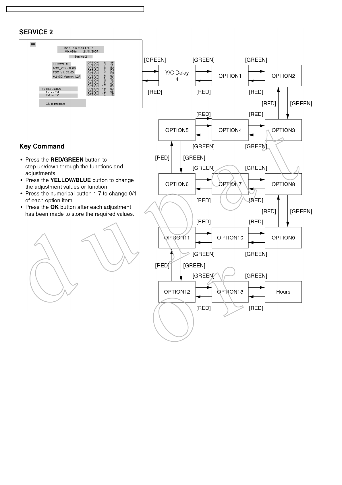
8.2. HowtoenterSERVICE2
1. EntertheSERVICE1mode.
2. SetthechanneltoCH99.
3. PressHOLDbuttononremotecontrol.
Note:
ToexittoServicemode,pressNorPowerbuttononremotecontrol.
18

TX-32LXD50/TX-26LXD50/TX-32LX50F/TX-32LX50P/TX-26LX50F/TX-26LX50P
19
TX-32LXD50/TX-26LXD50/TX-32LX50F/TX-32LX50P/TX-26LX50F/TX-26LX50P
20
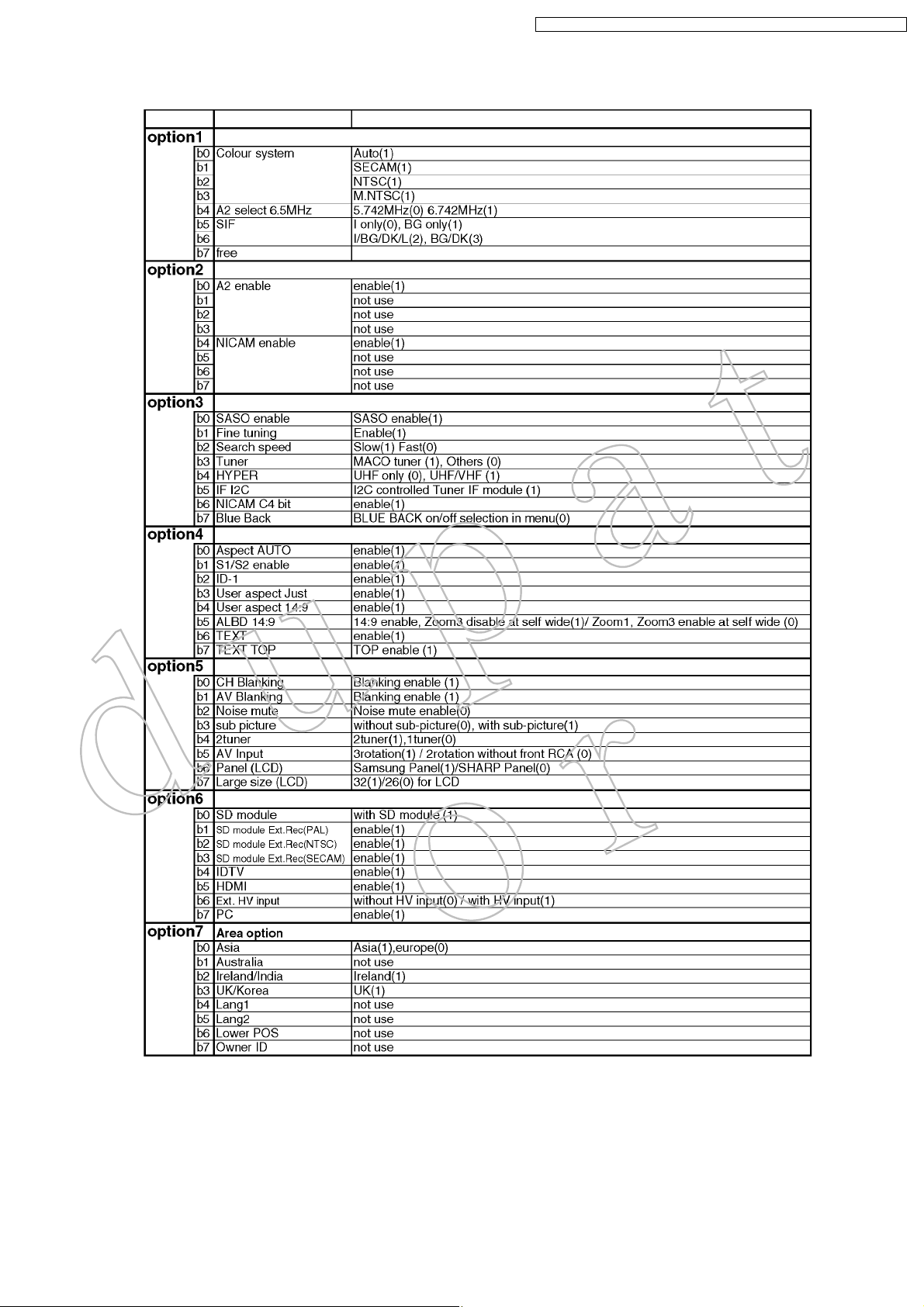
8.3. OptionDescription
TX-32LXD50/TX-26LXD50/TX-32LX50F/TX-32LX50P/TX-26LX50F/TX-26LX50P
21

TX-32LXD50/TX-26LXD50/TX-32LX50F/TX-32LX50P/TX-26LX50F/TX-26LX50P
22
TX-32LXD50/TX-26LXD50/TX-32LX50F/TX-32LX50P/TX-26LX50F/TX-26LX50P
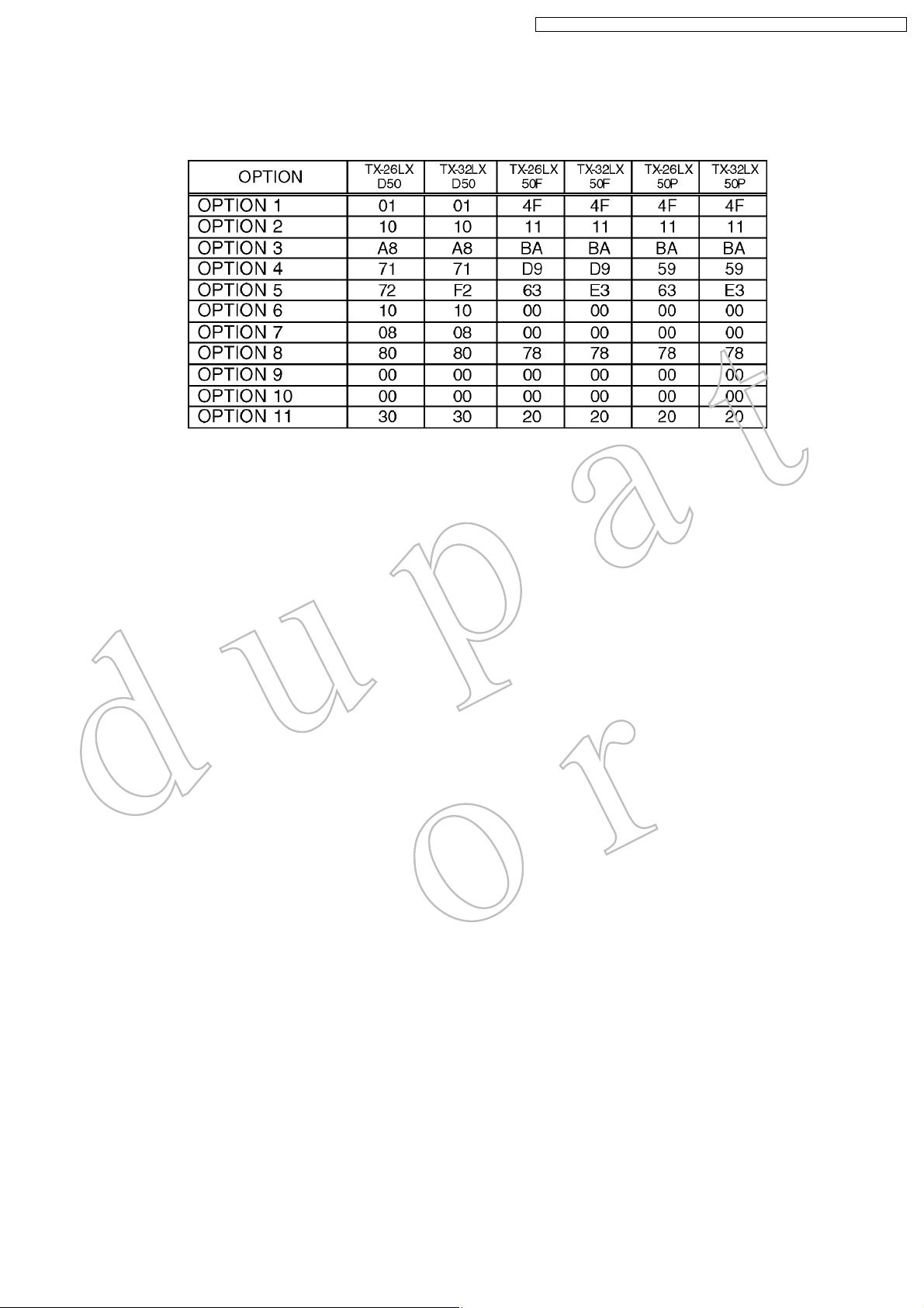
8.4. OptionCodeSetting
IfthememoryIC(IC1107)orDGBoardisreplaced,optioncodeshouldbere-memorized.
Ifyouuseforothermodel,youshouldre-memorizedthedifferentoptioncodeinSERVICE2mode.
23
TX-32LXD50/TX-26LXD50/TX-32LX50F/TX-32LX50P/TX-26LX50F/TX-26LX50P
9 Adjustmentmethod
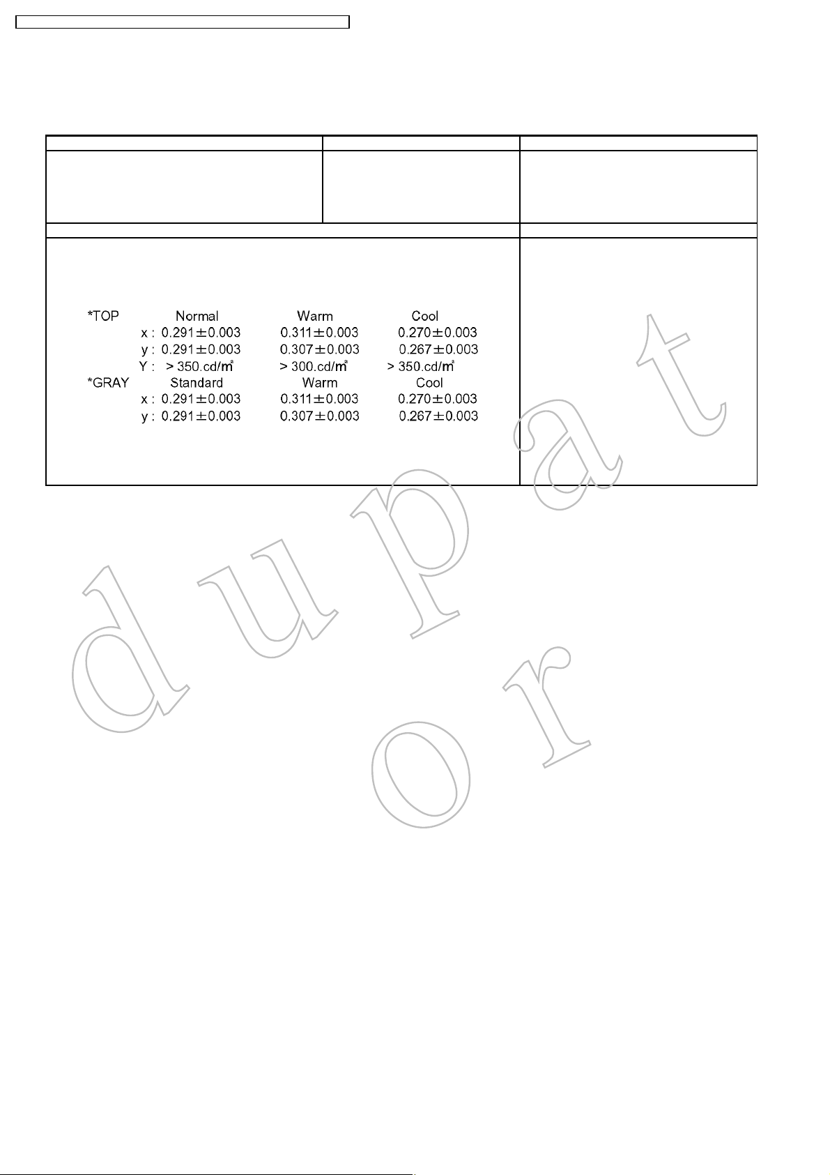
9.1. WhiteBalanceAdjustment
InstrumentName Connectto Remarks
1. Remotecontroller
2. LCDWBmeter(MinoltaCS-1000Aequivalent)
3. Communicationjig
4. Computerforexternalcontrol
Procedure Remarks
1. ProcedureBasicallyperformcheckingusingtheproductionsoftwareandmakeautomatic
adjustmentusingexternalcomputer.
2. ItadjustsinthemodeofColourbalanceNormal/Warm/Coolasfollows.
(UK/Euromodel)
CorrelationcanbealsotakenbyCA-210or
equivalent
Letthepanelstandformorethan3hoursat
morethan20°C.
Basicallyperformassembletocompletionin
theambientenvironmentofroomtemperature
morethan20°C.
Theagingtimeismorethan20minatabove
roomtemperature
*TheaddressofEEPROMtowriteisasfollows.
Add.C80-C91
24
TX 32LX D5 0 / TX 2 6LX D50 / T X 3 2L X50 F / TX 3 2LX 50P / T X 2 6LX 50F / T X 2 6LX 50 P
ÍÞÑð
ÍÞ×ð
25
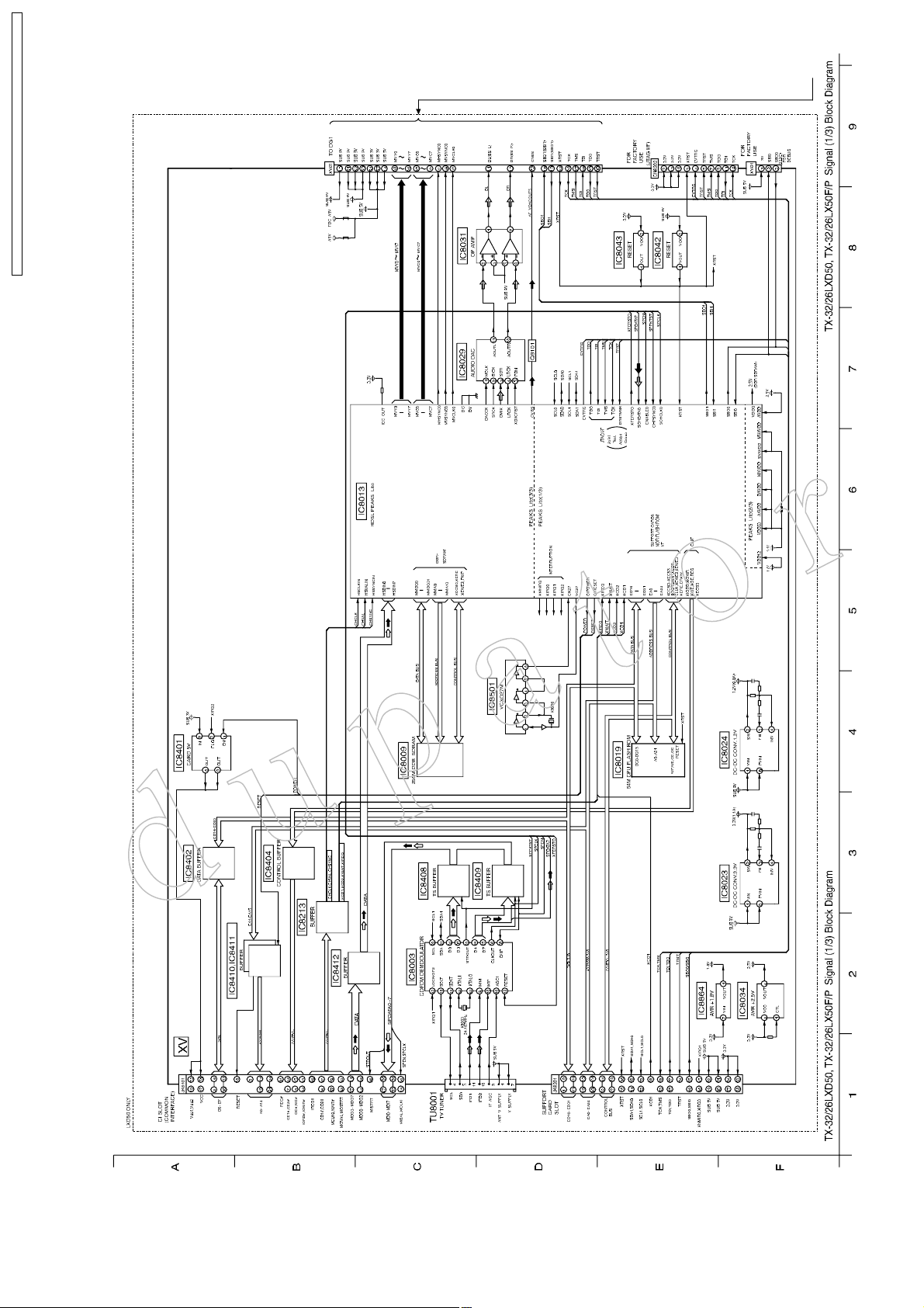
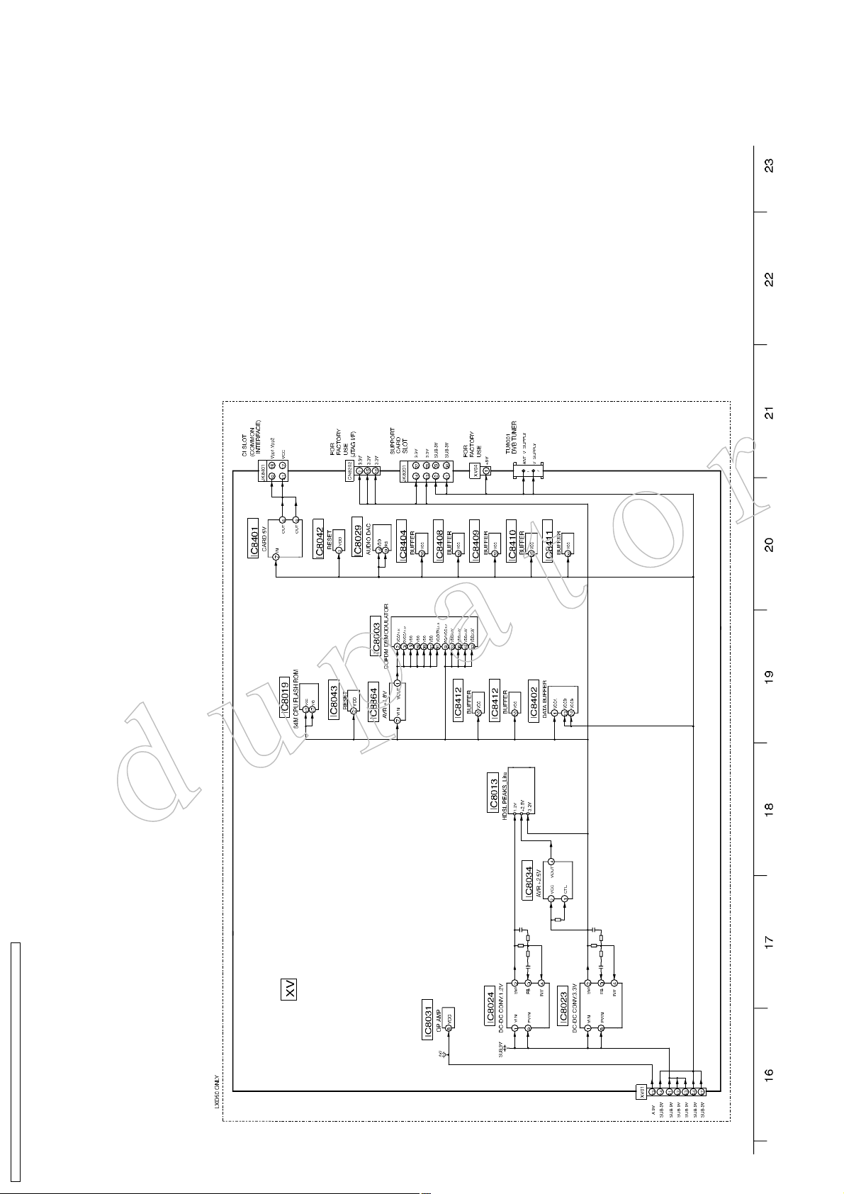
10 Block Diagram
ÈÝÜï
10.1. Signal (1/3) Block Diagram
ÚÞ
26
ÜÊÞÊ
МИуносокФИЬлрф МИуносокФИлрЪсР Н·¹²¿´ шоснч Ю´±½µ Ь·¿¹®¿³ МИуносокФИЬлрф МИуносокФИлрЪсР Н·¹²¿´ шоснч Ю´±½µ Ь·¿¹®¿³
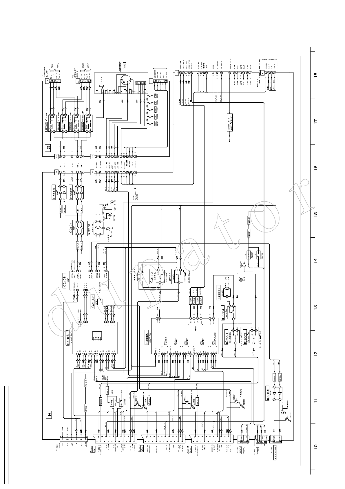
10.2. Signal (2/3) Block Diagram
TX 32LX D5 0 / TX 2 6LX D50 / T X 3 2L X50 F / TX 3 2LX 50P / T X 2 6LX 50F / T X 2 6LX 50 P

TX 32LX D5 0 / TX 2 6LX D50 / T X 3 2L X50 F / TX 3 2LX 50P / T X 2 6LX 50F / T X 2 6LX 50 P
ймолУШ¦±мФЫИЭФХТч
приУШ¦¬±мФшЪОЭФХЧТч
27
10.3. Signal (3/3) Block Diagram
ÌÎÍÌ
ÌÜÑ
ÌÜ×
ÌÓÍ
ÌÝÕ
УКЭФХр
УКНЗТЭр
УШНЗТЭр
ÓÊÝé
ÓÊÝé
ÓÊÝé
ÓÊÝé
ÓÊÝé
ÓÊÝð
ÓÊÝð
ÓÊÝð
ÓÊÇé
ÓÊÇê
ÓÊÇë
ÓÊÇì
ÓÊÇí
ÓÊÇî
ÓÊÇï
ÓÊÇð
ÈÎÍÌ
НЮЧпшНЮСпч
НЮСпшНЮЧпч
ÝÊÞÍ
ЬФшЮНБФч
ЬОшЮНБОч
МИуносокФИЬлрф МИуносокФИлрЪсР Н·¹²¿´ шнснч Ю´±½µ Ь·¿¹®¿³ МИуносокФИЬлрф МИуносокФИлрЪсР Н·¹²¿´ шнснч Ю´±½µ Ь·¿¹®¿³
õ
ï
ОЫЪЫОЫТЭЫ
ЯТСЬЫ
í
î
ЭЯМШСЬЫ
õ
МИуносокФИЬлрф МИуносокФИлрЪсР
Р±©»® шпснч Ю´±½µ Ь·¿¹®¿³
КБСЛМп
КБСЛМп
СТсСЪЪп
КБСЛМо
СТсСЪЪо
ÊÁÒ
ÊÁÒ
омКСТ
îìÊ
îìÊ
îìÊ
îìÊ
öö
öö ö
ú
ÜÝó
ÜÝõ
öö
КБСЛМп
КБСЛМп
СТсСЪЪп
КБСЛМо
СТсСЪЪо
ÊÁ×Ò
ÊÁ×Ò
28
î
Î
ß
ï
í
Õ
ö
öö
ì
í
ÒÝ
ÒÝ
è
ïî
ÒÝ
ÒÝ
é
ïï
ÒÝ
ÒÝ
ê
ïð
ÒÝ
ç
ö
öö
ï
î
ÔÚÔÚÔÚ
í³
МИуносокФИЬлрф МИуносокФИлрЪсР
Р±©»® шпснч Ю´±½µ Ь·¿¹®¿³
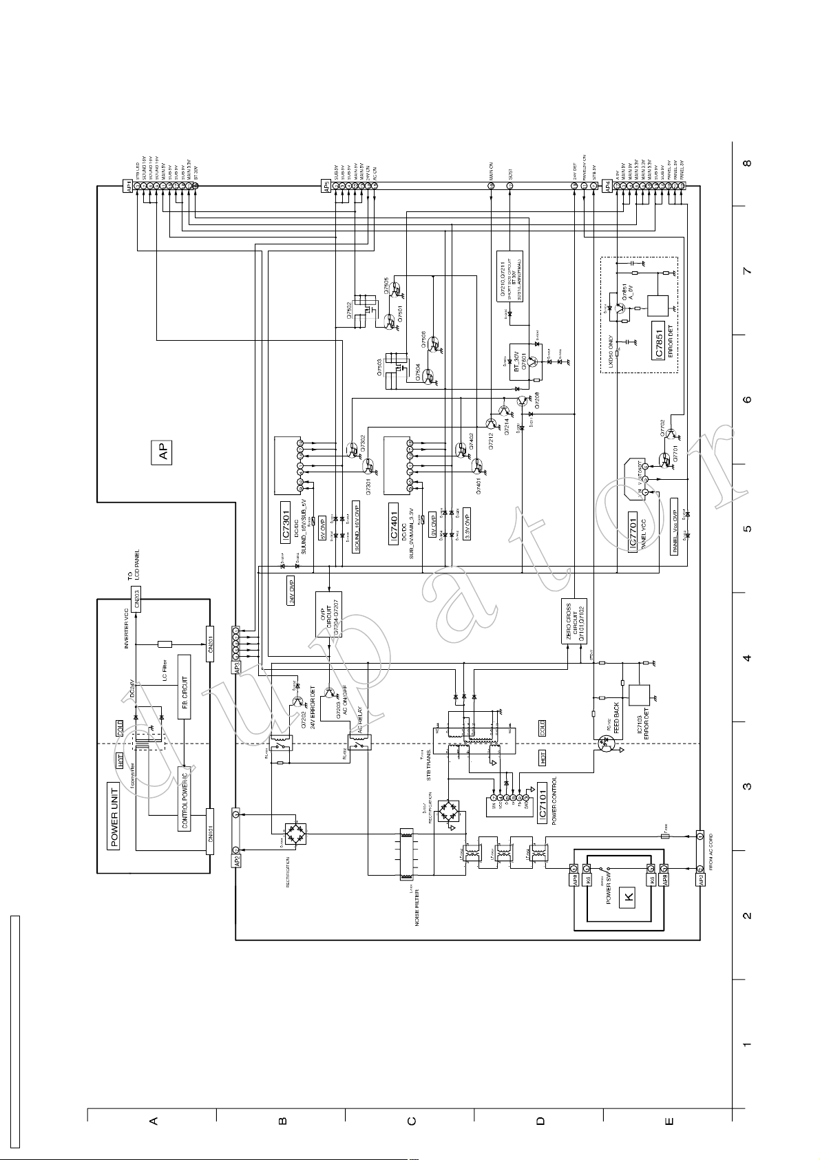
10.4. Power (1/3) Block Diagram
TX 32LX D5 0 / TX 2 6LX D50 / T X 3 2L X50 F / TX 3 2LX 50P / T X 2 6LX 50F / T X 2 6LX 50 P
МИуносокФИЬлрф МИуносокФИлрЪсР
TX 32LX D5 0 / TX 2 6LX D50 / T X 3 2L X50 F / TX 3 2LX 50P / T X 2 6LX 50F / T X 2 6LX 50 P
ÎÛÝ ÔÛÜ
Р±©»® шоснч Ю´±½µ Ь·¿¹®¿³
ОЫУСМЫ
ЯЧ НЫТНСО
ÕÛÇ ÍßÝÒ
ÔÛÜ Î
ÍÌÞ íòíÊ
ÍÑÍî
29
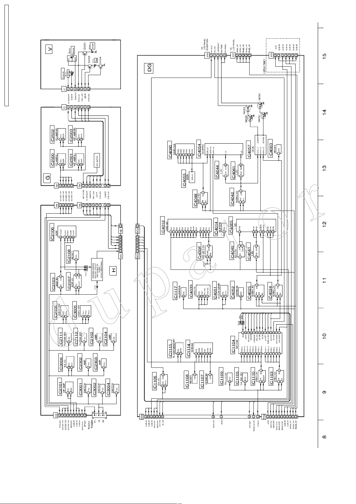
10.5. Power (2/3) Block Diagram
МИуносокФИЬлрф МИуносокФИлрЪсР
Р±©»® шоснч Ю´±½µ Ь·¿¹®¿³
МИуносокФИЬлрф МИуносокФИлрЪсР
Р±©»® шнснч Ю´±½µ Ь·¿¹®¿³
30
МИуносокФИЬлрф МИуносокФИлрЪсР Р±©»® шнснч Ю´±½µ Ь·¿ ¹®¿³
10.6. Power (3/3) Block Diagram
TX 32LX D5 0 / TX 2 6LX D50 / T X 3 2L X50 F / TX 3 2LX 50P / T X 2 6LX 50F / T X 2 6LX 50 P
 Loading...