

Panasonic TX-28SL1F, TX-25SL1F Diagram

TX-28/25SL1F Service Manual
Safety
Specifications
Parts List
Service
Information
Adjustments
Self Check
Service Hints
Mechanical
View
Disassembly
Location of
Controls
Waveforms
Block Diagrams
Schematic Diagrams
PCB Views
Service Support
Service and repair of
this product is
supported by
Panasonic's LUCI
interface.
This interface provides a
link between the TV and
a standard PC to allow a
number of diagnostic
and control functions to
be performed.
For more details contact
your local Panasonic
company.
BACK
EXIT
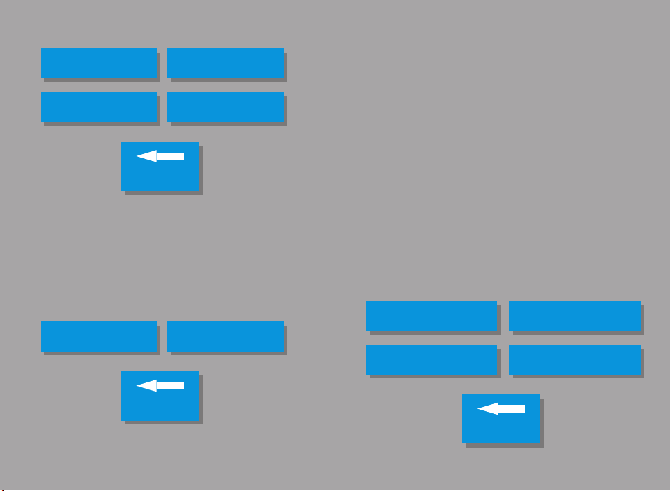
Audio
Control
Power supply
BACK
E - PCB Y - PCB
BACK
Video
E - Schematic
N - Schematic
H - Schematic
Y - Schematic
BACK

ORDER No. SM-98055
Colour Television
TX-28SL1F / TX-25SL1F
EURO4 Chassis
SPECIFICATIONS
(Information in brackets { } refer to TX-25SL1F)
Power Source: 220-240V AC, 50Hz
Power Consumption: 85W
Aerial Impedance: 75Ω unbalanced, Coaxial Type
Standby Power Consumption: 1,8W
Receiving System: PAL-I, B/G, H, D/K, PAL-525/60
Receiving Channels:
VHF E2-E12 VHF H1-H2 (ITALY)
VHF A-H (ITALY) VHF R1-R2
VHF R3-R5 VHF R6-R12
UHF E21-E69 CATV (S01-S05)
CATV S1-S10 (M1-M10) CATV S11-S20 (U1-U10)
CATV S21-S41 (HYPERBAND)
Intermediate Frequency:
Video 38,9MHz, 34MHz
Sound 32,9MHz, 33,4MHz, 33,16MHz
Colour 34,47MHz (PAL)
Video/Audio Terminals:
AUDIO MONITOR OUT Audio (RCAx2) 500mV rms1k
AV1 IN Video (21 pin) 1V p-p 75
AV1 OUT Video (21 pin) 1V p-p 75
AV2 IN Video (21 pin) 1V p-p 75
AV2 OUT Video (21 pin) 1V p-p 75
AV3 IN Audio (RCAx2) 500mV rms10k
High Voltage: 28,5kV ±1kV {28,2kV ±1kV}
Picture Tube: A66EAK071X11 66cm
Audio Output: 2 x 15W (Music Power)
Headphones 8Ω Impedance
Accessories supplied: Remote Control
Dimensions:
Height: 596,5 mm {550,5 mm}
Width: 778 mm {730 mm}
Depth: 479 mm {478,5 mm}
Net Weight: 32kg {27kg}
Specifications are subject to change without notice.
Weights and dimensions shown are approximate.
NOTE: This Service Manual should be used in conjunction with the
EURO4 technical guide.
SECAM L/L’, B/G, D/K
M.NTSC
NTSC (AV only)
32,4MHz, 40,4MHz, 33,05MHz
32,66MHz
34,5MHz, 34,65MHz (SECAM)
Audio (21 pin) 500mV rms 10k
RGB (21 pin)
Audio (21 pin) 500mV rms 1k
Audio (21 pin) 500mV rms 10k
S-Video IN Y: 1V p-p 75
(21 pin) C: 0.3V p-p 75
Audio (21 pin) 500mV rms 1k
Selectable Output (21 pin)
Video (RCAx1) 1V p-p 75
{A59EAK071X11 59cm}
8Ω Impedance
2 x R6 (UM3) Batteries
Ω
Ω
Ω
Ω
Ω
Ω
TECHNISCHE DATEN
(Werte in klammern gelten { } nur fur TX-25SL1F)
Netzpannung: 220-240V AC, 50Hz
Leistungsaufnahme: 85W
Antennenimpedanz: 75Ω asymmetrisch, Koaxial-Typ
Standby Leistungsaufnahme: 1,8W
Empfangssystem: PAL-I, B/G, H, D/K, PAL-525/60
Empfangsbereiche:
VHF E2-E12 VHF H1-H2 (ITALY)
VHF A-H (ITALY) VHF R1-R2
VHF R3-R5 VHF R6-R12
UHF E21-E69 CATV (S01-S05)
CATV S1-S10 (M1-M10) CATV S11-S20 (U1-U10)
CATV S21-S41 (HYPERBAND)
Zwischenfrequenz:
Video 38,9MHz, 34MHz
Sound 32,9MHz, 33,4MHz, 33,16MHz
Colour 34,47MHz (PAL)
Ω
Ω
Ω
Ω
Ω
Ω
Ω
Video/Audio Anschlüsse:
AUDIO MONITOR OUT Audio (RCAx2) 500mV rms1k
AV1 EINGANG Video (21 pin) 1V p-p 75
AV1 AUSGANG Video (21 pin) 1V p-p 75
AV2 EINGANG Video (21 pin) 1V p-p 75
AV2 AUSGANG Video (21 pin) 1V p-p 75
AV3 EINGANG Audio (RCAx2) 500mV rms10k
Hochspannung: 28,5kV ±1kV {28,2kV ±1kV}
Bildrohre: A66EAK071X11 66cm
Ton Ausgangsleistung: 2 x 15W (Musikleistung)
Lautsprecher 8Ω Impedanz
Kopfhörer: 8Ω Impedanz
Mitgel. Zubehör: Fernbedienung
Abmessungen:
Höhe: 596,5 mm {550,5 mm}
Breite: 778 mm {730 mm}
Tiefe: 479 mm {478,5 mm}
Gewicht: 32kg {27kg}
Änderungen der Technisichen Daten vorbehalten.
Gewichte und Abmessungen sind Näherungsangaben.
Hinweis: Bitte verwende Sie das Service Manual zusammen mit dem
Technical Guide.
SECAM L/L’, B/G, D/K
M.NTSC
NTSC (nur AV Eingang)
32,4MHz, 40,4MHz, 33,05MHz
32,66MHz
34,5MHz, 34,65MHz (SECAM)
Audio (21 pin) 500mV rms 10k
RGB (21 pin)
Audio (21 pin) 500mV rms 1k
Audio (21 pin) 500mV rms 10k
S-Video IN Y: 1V p-p 75
(21 pin) C: 0.3V p-p 75
Audio (21 pin) 500mV rms 1k
Wählbarer Ausgang
Video (RCAx1) 1V p-p 75
{A59EAK071X11 59cm}
2 x R6 (UM3) Batterien
Ω
Ω
Ω
Ω
Ω
Ω
Ω
Ω
Ω
Ω
Ω
Ω
Ω

CONTENTS
SAFETY PRECAU TIO NS ....................................................2
SERVICE HINTS.................................................................4
SERVICE MODE.................................................................5
SELF CHECK......................................................................7
ADJUSTMENT PROCEDURE .............................................8
WAVEFORM PATTERN TABLE..........................................9
ALIGNMENT SETTINGS .....................................................10
BLOCK DIAGRAMS.............................................................12
PARTS LOCATION..............................................................16
REPLACEMENT PARTS LIST.............................................17
SCHEMATIC DIAGRAMS....................................................26
CONDUCTOR VIEWS.........................................................30
SAFETY PRECAUTIONS
GENERAL GUIDE LINES
1. It is advisable to insert an isolation transformer in the
AC supply before servicing a hot chassis.
2. When servicing, observe the original lead dress in the
high voltage circuits. If a short circuit is found, replace
all parts which have been overheated or damaged by
the short circuit.
3. After servicing, see that all the protective devices
such as insulation barriers, insulation papers, shields
and isolation R-C combinations are correctly
installed.
4. When the receiver is not being used for a long period
of time, unplug the power cord from the AC outlet.
5. Potentials as high as 29,5kV {29,2kV} are present
when this receiver is in operation. Operation of the
receiver without the rear cover involves the danger of
a shock hazard from the receiver power supply.
Servicing should not be attempted by anyone who is
not familiar with the precautions necessary when
working on high voltage equipment. Always
discharge the anode of the tube.
6. After servicing make the following leakage current
checks to prevent the customer from being exposed
to shock hazard.
LEAKAGE CURRENT COLD CHECK
1. Unplug the AC cord and connect a jumper between
the two prongs of the plug.
2. Turn on the receiver’s power switch.
3. Measure the resistance value with an ohmmeter,
between the jumpered AC plug and each exposed
metallic cabinet part on the receiver, such as screw
heads, aerials, connectors, control shafts etc. When
the exposed metallic part has a return path to the
chassis the reading should be between 4M ohm and
20M ohm. When the exposed metal does not have a
return path to the chassis the reading must be
infinite.
INHALT
SICHERHEITSVORKEHRUNGEN ...................................... 2
SERVICE HINWEISE..........................................................4
ABGLEICHVERFAHREN.....................................................6
SELBSTDIAGNOSE ............................................................ 7
ABGLEICH..........................................................................8
SIGNAL TABELLE...............................................................9
ABGLEICHTABELLE........................................................... 11
SCHALTBILD BLOCK..........................................................12
EXPLOSIONSZEICHNUNG.................................................16
ERSATZTEILLISTE.............................................................17
SCHALTBILD SCHEMA ...................................................... 26
ANSICHT DER LEITERBAHNEN ........................................ 30
SICHERHEITSVORKEHRUNGEN
ALLGEMEINE RICHTLINIEN
1. Es ist empfehlenswert einen Trenntransformator in
die Stromversorgung zu schalten, bevor Reparaturen
an einem Gerät vorgenommen werden, dessen
Chassis unter Spannung steht.
2. Bei der Durchführung von Servicearbeiten dürfen die
ursprünglichen Kabelanschlüsse nicht vertauscht
werden. Dies gilt insbesondere für die Anschlüsse im
Hochspannungsteil. Hat sich ein Kurzschluß ereignet,
dann sind alle Teile, an denen Spuren von
Überhitzung sichtbar sind, auszuwechseln.
3. Nach Beenden der Servicearbeiten ist
sicherzustellen, daß alle Sicherheitsvorrichtungen,
wie Isolationsstege, Isolationspapiere,
Abschirmungen und Isolations -R-C- Glieder wieder
richtig eingesetzt sind.
4. Wenn der Fernseher während längerer Zeit nicht in
Betrieb gesetzt wird, sollte der Netzstecker aus der
Netzsteckdose gezogen werden.
5. Im Betrieb sind Spannungen bis zu 29,5kV {29,2kV}
in diesem Gerät vorhanden. Die Inbetriebnahme des
Fernsehers ohne aufgesetzte Rückwand bringt die
Gefahr eines elektrischen Schlages von der
Fernseher - Stromversorgung mit sich.
Servicearbeiten solten daher auch nie durch
Personen versucht werden, die nicht in vollem.
Umfang mit den Sicherheitsvorkehrungen beim
Umgang mit Hochspannungsgeräten vertraut sind.
Vor der Handhabung mit der Bildröhre ist die Anode
der Bildrohre immer an dem Empfängerchassis zu
entladen.
6. Nach Beenden der Servicearbeiten sind die
folgenden Kriechstrom-Prüfungen durchzuführen, um
den Kunden vor der Gefahr eines elektrischen
Schlages zu schützen.
MESSUNG DES ISOLATIONSWIDERSTANDES
IM ABGESCHALTETEN ZUSTAND
1. Den Netsztecker aus der Netzsteckdose ziehen und
die beiden Steckerstifte kurzschließen.
2. Den Geräteschalter des Fernsehgerätes einschalten.
3. Mit einem Ohmmeter den Widerstandswert zwischen
dem überbrückten Netzkabelsteckerund jendem
zugänglichen Metallteil am Gehäuse des
Fernsehgerätes, wie Schraubenköpfe, Antennen,
Achsen der Regler, Griffassungen usw.messen.
Wenn ein zugängliches Metallteil keine Rückleitung
zum Chassis hat, Muß die Anzeige unendlich
betrgen.
2

LEAKAGE CURRENT HOT CHECK
1. Plug the AC cord directly into the AC outlet. Do not
use an isolation transformer for this check.
2. Connect a 2kΩ 10W resistor in series with an
exposed metallic part on the receiver and an earth,
such as a water pipe.
3. Use an AC voltmeter with high impedance to
measure the potential across the resistor.
4. Check each exposed metallic part and check the
voltage at each point.
5. Reverse the AC plug at the outlet and repeat each of
the above measurements.
6. The potential at any point should not exceed 1,4 V
rms. In case a measurement is outside the limits
specified, there is a possibility of a shock hazard, and
the receiver should be repaired and rechecked before
it is returned to the customer.
HOT CHECK CIRCUIT
SCHALTUNGSAUFBAU FÜR PRUFUNG
IM EINGESCHALTETEN ZUSTAND
A.C. VOLTMETER
WECHSELSTROM-VOLTMETER
TO INSTRUMENT’S
EXPOSED
METALLIC PARTS
MESSUNG DES KRIECHSTROMS IM
EINGESCHALTETEN ZUSTAND
1. Den Netzstecker direkt in eine Netsteckdose stecken.
Für diese Messung keinen Trenntransformator
verwenden.
2. Einen 2kΩ / 10W-Widerstand in Serie mit einem von
außen zugänglichen Metallteil am Fernsehgerät und
einer guten, Erdung z.B Wasserleitung, anschließen.
3. Ein Wechselstrom-Voltmeter mit einem Meßbereich
von 1000 Ohm.Volt oder größer verwenden, um die
Spannung über den Widerstand zu messen.
4. Jedes zugängliche Metallteil prüfen, und an jedem
Punkt dies Spannung messen.
5. Den Netztecker umgekehrt in die Steckdose stecken
und jede der obigen Messungen wiederholen.
6. Die Spannung darf an keinem der Punkte 1,4V eff.
überschreiten. Wird dieser Wert nicht eingehalten,
besteht die Gefar eines elektrischen Schlages, und
das Fernsehgerät sollte daher repariert und
nachgeprüft werden, bevor es an den Kunden
zurückgegeben wird.
AN ZUGANGLICHE
METALLTEILE DAS
TV-GERATES
2k ohm
Water Pipe
(Earth)
Wasserleitung
(Erdung)
Fig.1.
Abb.1.
X-RADIATION WARNING
1. The potential sources of X-Radiation in TV sets are
the high voltage section and the picture tube.
2. When using a picture tube test jig for service, ensure
that the jig is capable of handling 29,5kV without
causing X-Radiation.
NOTE : It is important to use an accurate
periodically calibrated high voltage meter.
1. Set the brightness to minimum.
2. Measure the high voltage. The meter should indicate
28,5kV± 1kV {28,2kV± 1kV}. If the meter indication is
out of tolerance, immediate service and correctio n is
required to prevent the possibility of premature
component failure.
3. To prevent any X-Radiation possibility, it is essential
to use the specified tube.
RÖNTGENSTRAHLUNG ACHTUNG :
1. Potentielle Quellen von Röntgenstrahlung in
Fernsehgeräten sind das Hochspannungsteil und die
Bildröhre.
2. Bei Verwendung eines Bildröhren-Prüfgerätes für den
Service ist sicherzustellen, daß es für die Belastung
von 29,5kV geeignet ist, ohne daß eine
Röntgenstrahlung verursacht wird.
ANMERKUNG : Es ist wichtig, daß ein präzises,
regelmäßig geprüftes Voltmeter verwendet wird.
1. Helligkeit auf Minimum stellen.
2. Die Hochspannung messen. Die Anzeige des
Instrumentes sollte 28,5kV ± 1kV {28,2kV± 1kV}.
Falls die Anziege diese Toleranzgrenzen
überschreitet, ist die sofortige Behebung nötig, um
die Möglichkeit vorzeitigen Komponentenausfalls zu
verhüten.
3. Um die Möglichkeit von Röntgenstrahlung zu
begrenzen, ist es wichtig, daß nur die
vorgeschriebene Bildröhre verwendet wird.
3
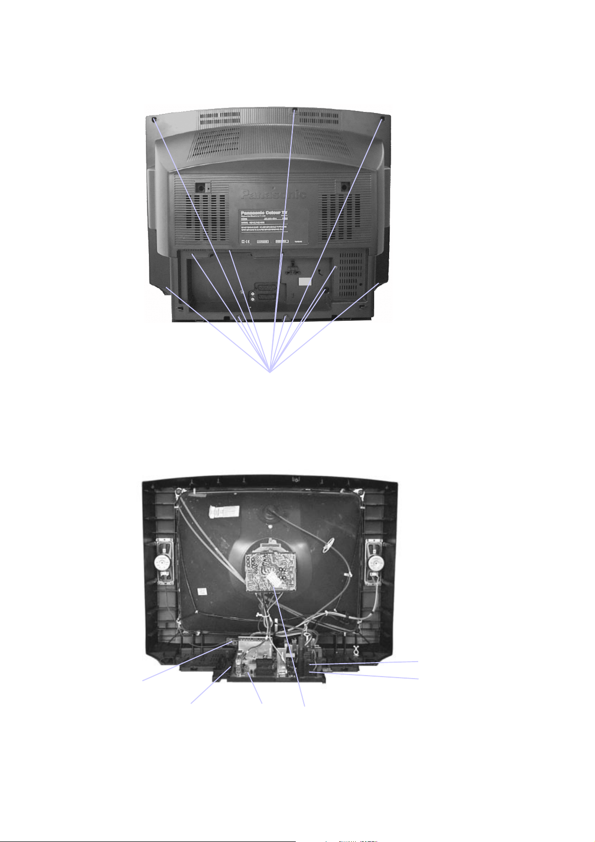
SERVICE HINTS
HOW TO REMOVE THE REAR COVER
1. Remove the 12 screws as shown in Fig.2.
SERVICE HINWEISE
ENTFERNEN DER GERÄTERÜCKWAND
1. Die 12 Schrauben entfernen, siehe Abb.2.
Screws
Schrauben
Fig.2.
Abb.2.
LOCATION OF CONTROLS LAGE DER EINSTELLREGLER
Focus
N - Board
E - Board
H - Board
Fig.3.
Abb.3.
Screen
Y - Board
4
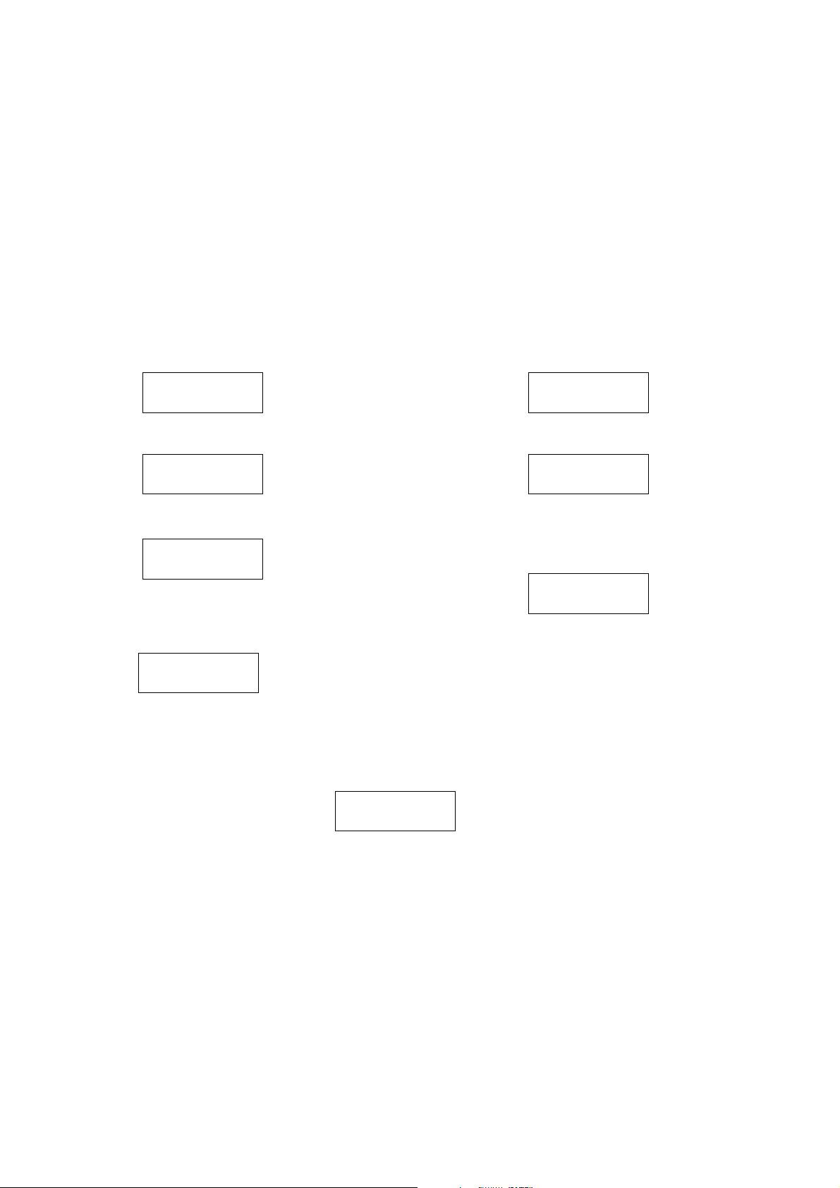
SERVICE MODE
The remote control is used for entering and storing adjustments, with the exception of Cut-off adjustments, which must
always be done prior to service adjustment. Perform adjustments in accordance with screen display. The display on the
screen also specifies the CCU variants as well as the approx. setting values. The adjustment sequence for the service mode
is indicated below.
2. Press the RED / GREEN buttons to step up / down
1. Set the Bass to maximum position, set the Treble to
minimum position, press the volume down button
(-/v) on the customer controls at the front of the TV
and at the same time press the INDEX button on the
remote control, this will place the TV into the Service
Mode.
NOTE: This TV also has the option of using a Memory Pack which enables you to copy the preset TV channels into the
Memory Pack and then download them onto this or any other EURO-4 TV set.
TV to Memory Pack process
1. Plug the memory pack into the AV1 21 pin terminal at
the back of the TV and switch the TV on.
2. Go into Service Mode as explained above. The
screen will show :-
through the functions.
3. Press the YELLOW / BLUE buttons to alter the
function values.
4. Press the STR button after each adjustment has
been made to store the required values.
5. To exit the Service Mode, press the "N" button.
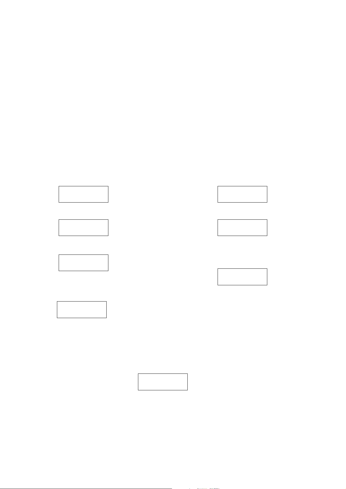
Memory Pack to TV process
1. Plug the memory pack into the AV1 21 pin terminal at
the back of the TV and switch the TV on.
2. Go into the Service Mode as explained above. The
screen will show :-
Program
External>>TV
3. Press the BLUE button on the remote control. The
screen will show :-
Program
TV>>External
4. Press the STR button on the remote control. The
screen will show :-
Please Wait
5. All the tuning information stored inside the TV will
now be transferred to the Memory Pack. This process
will take 2-3 minutes to complete and when finished
the screen will show :-
Complete
3. Press the STR button on the remote control. The
screen will show :-
4. All the tuning information stored inside the Memory
Pack will now be transferred to the TV. This process
will take 2-3 minutes to complete and when finished
the screen will show :-
5. The tuning information from the Memory Pack has
now been copied into the TV.
6. To exit from the Service Mode press the "N" button.
7. The process has now been completed and the
Memory Pack can now be removed.
Program
External>>TV
Please Wait
Complete
ERRORS
If an error occurs while using the Memory Pack the TV will detect this and the screen will show: -
Error !!
If this happens then press the "N" button and repeat the process that was being used. If the errors continue to occur then
check the connectors between the TV and the memory pack and check the 9V battery inside the memory pack.
5
ABGLEICHVERFAHREN
Die Fernbedienung dient zum Eingeben und Abspeichern der Einstellwerte, mit Ausnahme der Sperrpunkteinstellung, die
grundsätzlich vor den hier beschriebenen Einstellungen vorgenommen werden muss. Die Einstellungen erfolgen
entsprechend dem Bildschirm-Display. Auf dem Bildschirm-Display erscheinen die ungefähren Einstellwerte. Die Einstellfolge
für den Service-Modus ist nachstehend beschrieben.
4. Die einzelnen Funktionen mit Hilfe der ROTEN und
1. Um in den Service-Mode zu gelangen, gehen sie
bitte wie folgt vor.
2. Stellen sie im Toneinstellungs-Menü die Bässe auf
Maximun und die Höhen auf Minimum.
3. Halten sie die INDEX-Taste auf der Fernbedienung
gedrückt und drücken zusätzlich die Taste -/v im
Bedienteil des TV-Gerätes. Auf dem Bildschirm
erscheint die entsprechende Anzeige für den
Service-Mode.
HINWEIS: Dieses FS-Gerät bietet auch die Möglichkeit eines Memory Pack, mit dem Sie die gewählten Fernsehkanäle
abspeichern und auf jedes beliebige EURO-4 FS-Gerät umkopieren können.
Kopieren der Einstelldaten vom FS-Gerät in das
Memory Pack.
1. Das Memory Pack in die AV1-Buchse an der
Rückseite des FS-Gerätes stecken und das Gerät
einschalten.
2. Wie schon oben beschrieben auf Service-Modus
umschalten. Auf dem Bildschirm erscheint :-
GRÜNEN Taste anwählen.
5. Mit der GELBEN und BLAUEN Taste die Werte der
einzelnen Funktionen ändern.
6. Nach jeder Einstellung die Taste STR auf der
Fernbedienung drücken, um die geänderten Werte
abzuspeichern.
7. Zum Verlassen des Service-Modus die "N" - Taste
auf der Fernbedienung drücken.
Kopieren der Einstelldaten vom Memory Pack in
das FS-Gerät.
1. Das Memory Pack in die AV1-Buchse an der
Rückseite des FS-Gerätes stecken und das Gerät
einschalten.
2. Wie schon oben beschrieben auf Service-Modus
umschalten. Auf dem Bildschirm erscheint :-
Program
External>>TV
3. Nun die BLAUE Taste an der Fernbedienung
betätigen. Auf dem Bildschirm erscheint :-
Program
TV>>External
4. Nun die STR Taste an der Fernbedienung betätigen.
Der Bildschirm meldet nun :-
Please Wait
5. Die im FS-Gerät abgespeicherten KanalEinstelldaten werden nun in das Memory Pack
überspielt. Bei abgeschlossener Datenübertragung
meldet der Bildschirm :-
Complete
FEHLER
Program
External>>TV
3. Nun die STR Taste an der Fernbedienung betätigen.
Der Bildschirm meldet nun :-
Please Wait
4. Die im Memory Pack abgespeicherten KanalEinstelldaten werden nun in das FS-Gerät überspielt.
Bei abgeschlossener Datenübertragung meldet der
Bildschirm :-
Complete
5. Die Kanal-Einstelldaten sind damit von Memory Pack
in das das FS-Gerät überspielt.
6. Zum Verlassen des Service-Modus die "N" - Taste
auf der Fernbedienung drücken.
7. Das Kopiervorgang ist somit abgeschlossen, und das
Memory Pack kann von der Steckerleiste abgezogen
werden.
Falls beim Gebrauch des Memory Packs Fehler aufreten, zeigt das FS-Gerät dies auf dem Bildschirm mit der folgenden
Meldung an : -
Error !!
In diesem Fall muss der Service-Modus durch Drücken der "N" - Taste auf der Fernbedienung verlassen und anschliessend
der Vorgang wiederholt werden. Falls weiterhin Fehlermeldungen erscheinen, müssen die Anschlusskontakte zwischen FSGerät und Memory Pack sowie die 9V Batterie im Memory Pack kontrolliert werden.
6
SELF CHECK
technischen Informationen.
,
1. Self-check is used to automatically check the bus
lines and hexadecimal code of the TV set.
2. To get into the Self-Check mode press the down
(-/v) button on the customer controls at the front of
the set,at the same time pressing the STATUS
button on the remote control, and the screen will
show :-
SELBSTDIAGNOSE
1. Die Selbstdiagnose dient zum automatischen Prüfen
der Bus-Leitungen sowie des Hexadezimalcodes des
FS-Geräts. Zum Umschalten auf Selbstdiagnose
zunächst die Taste "STATUS" auf der
Fernbedienung und gleichzeitig die-Taste am
Bedienteil des FS-Gerätes drücken (-/v), auf dem
Bildschirm erscheint hierauf :-
2. Nach der Selbstdiagnose wird das Gerät automatisch
auf sämtliche werksseitigen Standardeinstellungen
zurückgesetzt :-
VDP O.K.
TUN O.K.
E2 O.K.
MSP O.K.
DPL - -
OPTION 1 39
OPTION 2 0C
OPTION 3 1F
OPTION 4 00
OPTION 5 CF
OPTION 6 25
If the CCU ports have been checked and found to be incorrect or not located then " - - " will appear in place of "O.K.".
Wenn der Hauptprozesser (CCU) an den Anschlüssen einen Fehler erkennt, oder der entsprechende Anschluss nicht belegt
zeigt die entsprechende Position " - - " anstelle von OK an.
ist
Service Aids
To aid in the service of our current chassis there are a number
of Service Aids which have been made available.
• LUCI interface kit (Linked Utility Computer Interface)
Part number: TZS6EZ002
This contains interface and cables for connecting TV
service connector and a PC as well as diagnostic software.
As new models are introduced upgrade software will
become available.
PCB O.K.
Cab O.K.
Sum Factory use
only
Nur für
Herstellung
Service-Hilfen
Zur Unterstützung der Servicearbeiten stehen weitere
Hilfsmittel zur Verfügung.
• LUCI interface kit (PC-unterstützes Diagnosesystem)
Bestell-Nr.: TZS6EZ002
Es beinhaltet ein Interface, die Anschlusskabel zum FSGerät und die Diagnose-Software. Bei Einführung von
neuen Modellen ist ein Update der Software jederzeit
möglich.
• VICI (Visual Interactive Computer Information)
These C.D.'s contain multimedia documentation providing
quick access to service information.
Part No. TZS7EZ006 & TZS7EZ005
1. Service Manuals
2. Instruction Books
3. Technical Information
• TASMIN (Technically Advanced System for Multimedia
Interactive Notes)
As well as providing a first step towards more interactive
training this product also achieves quick access to
Technical Information.
• VICI (Interaktive CD-ROM) mit schnellem Zugiff auf
Serviceinformationen.
Bestell-Nr.:TZS7EZ006 & TZS7EZ005
1. Service Manuals
2. Bedienungsanleitungen
3. Technical Information
• TASMIN (Technisch erweitertes System für interaktive
Multimedia-Hinweise und Notizen)
Genauso wie dieses Produkt einen ersten Schritt in
Richtung erweitertes interaktives Training bereitstellt,
ermöglicht es einen noch schnelleren Zugang zu
7
ADJUSTMENT PROCEDURE
Item/Preparation Adjustments
+B SET-UP
1. Receive a Greyscale signal.
2. Set the controls:Brightness Minimum
Contrast Minimum
Volume Minimum
Cut-Off / Ug2 Test
1. Receive a Greyscale signal.
2. Degauss the tube externally.
3. Set the TV into Service Mode 1.
4. Select Cutoff mode.
1. Set the +B voltage up as follows:Adjust R811 so that B2 shows 148V±1V
2. Confirm the following voltages.
B9 5 ± 0,25V B10 5 ± 0,25V
B5 12 ± 0,5V B11 33 ± 1,5V
B4 16 ± 1V B7 8 ± 0,5V
B12 26 ± 1V B8 5,5 ± 0,5V
B3 35 ± 1V B13 15 ± 1V
B1 200 ± 10V B14 -15 ± 1V
To adjust Cutoff connect an oscilloscope to the blue
cathode, adjust "cutoff" value using the "Yellow" and
"Blue" buttons until the black level is 160V±5V press
"STR" to store the value. Remove the oscilloscope.
Select Ug2 adjustment and adjust the screen VR until the
display shows "O.K."
ABGLEICH
Vorbereitungen Abgleich
+B - Abgleich
1. Testbild empfangen.
Helligkeit aufMinimum
Kontrast auf Minimum
Lautstärke Minimum
Cut-Off / Ug2 Test
1. Testbild empfangen.
2. Bildröhre entmagnetisieren.
3. Service-Mode 1 anwählen.
4. Im Service-Mode den Abgleichpunkt Cutoff DC-Mode
wählen .
1. Mit R811 muß die B2 auf 148V± 1V einges tel lt
werden.
2. Folgende Spannungen sind zu überprüfen.
B9 5 ± 0,25V B10 5 ± 0,25V
B5 12 ± 0,5V B11 33 ± 1,5V
B4 16 ± 1V B7 8 ± 0,5V
B12 26 ± 1V B8 5,5 ± 0,5V
B3 35 ± 1V B13 15 ± 1V
B1 200 ± 10V B14 -15 ± 1V
Einen Oszillographen an die blaue Katode der Bildröhre
anschliessen. Mit der gelben und blauen Taste den
CUT-OFF Wert auf 160V±5V abgleichen und mit der
STR-Taste abspeichern. Den Oszillograph entfernen und
den Ug2 Test aufrufen. Den Abgleichwert solange
ändern, bis OK auf dem Bildschirm erscheint. Den Wert
abspeichern.
8

Vert Out
IC601 Pin 31
WAVEFORM PATTERN TABLE SIGNAL TABELLE
Vert Drive
IC451 Pin 2
VFLB
IC451 Pin 3
0.7V
H - Out
IC601 Pin 50
3V
HFLB
IC601 Pin 13
6.2V
20mS
64µS
64µS
57V
H - Out
IC701 Pin 5
30mV
HFLB
IC701 Pin 8
1.5V
20mS
64µS
64µS
1V
20mS
H - Pulse
Base Q503
2V
64µS
Video Out
IC601 Pin 59
2V
64µS
R - Out
IC601 Pin 37
275mV
R - Out
E8 Pin 5
4.6V
SCL
IC1201 Pin 3
3.7V
64µS
64µS
G - Out
IC601 Pin 38
275mV
G - Out
E8 Pin 3
4.4V
SVM Out
IC601 Pin 34
88mV
64µS
64µS
B - Out
IC601 Pin 39
275mV
64µS
B - Out
E8 Pin 4
4.6V
64µS
13µS
64µS
9
 Loading...