

Page 1

Operating Instructions
Wide LCD TV
Model No.
TX-26LE60F
TX-32LE60F
Please read these instructions before operating your set
and retain them for future reference.
English
Page 2

Dear Panasonic Customer,
We hope that you have many years of enjoyment from your new TV. The Quick Start Guide section at the be gin ning of
this instruction book will allow you to use the TV as quickly as possible. We recommend that you then read the complete
instruction book, and keep it to refer to as you explore the range of advanced features that this LCD TV offers.
Contents
Accessories ................................................................ 2
Warnings and Precautions ......................................... 3
Fitting remote control batteries ................................... 3
Installation .................................................................. 4
How to use the LCD stand.......................................... 4
Maintenance ............................................................... 4
Quick Start Guide ....................................................... 5
Basic controls: control panel and remote control........ 7
Using the On Screen Displays.................................... 8
Programme guide ....................................................... 8
Picture menu .............................................................. 9
Sound menu ............................................................. 10
Setup menu ...............................................................11
Tuning menu – overview .......................................... 12
Tuning menu – Programme edit ............................... 13
Adding / deleting a programme channel ................ 13
Moving a programme channel ............................... 13
Tuning a programme channel ................................ 13
Renaming a programme channel .......................... 14
Locking a programme channel .............................. 14
Changing the sound system for a channel ............ 14
Copying programme information to a recording
device ................................................................. 14
Tuning menu – Auto setup ........................................ 15
Tuning menu – Manual tuning .................................. 16
Manual tuning (via control panel) ............................. 16
Q-Link ....................................................................... 17
Aspect Controls ........................................................ 18
VCR / DVD operation ............................................... 20
Teletext operation ..................................................... 21
Still ............................................................................ 23
Connections.............................................................. 24
How to connect the Headphones / AV3 terminals . 24
How to connect the AV1 / 2 Scart terminals .......... 25
How to connect the Component Input terminals ... 25
How to connect the HDMI Input terminal ............... 26
Input signal that can be displayed ........................... 27
Scart, S-video and HDMI terminals information ....... 27
Troubleshooting ........................................................ 28
Specifi cations ........................................................... 29
Accessories
Check that you have the accessories and items shown
Operating
Instructions
2
Remote Control
Transmitter
(EUR7651030A)
Batteries for the
Re mote Control
Transmitter
(2 × R6 (UM3) size)
Clamper
Pan European
Guarantee Card
Page 3
Warnings and Precautions
• This TV set is designed to operate on AC 220-240 V,
50 Hz.
• To prevent damage which might result in elec tric shock
or fi re, do not expose this TV set to rain or excessive
moisture. This TV must not be exposed to dripping or
splashing water and ob jects fi lled with liq uid, such as
vases, must not be placed on top of or above the TV.
• Keep unneeded small parts and other objects out
of the reach of small children. These objects can
be accidentally swallowed. Also, be careful about
packaging materials and plastic sheets.
• Use only the accessories appropriate to handling with
fragile products.
• To prevent injury, this apparaturs must be securely
attached to the fl oor/wall in accordance with installation
instructions (mounting bracket is not supplied) .
• WARNING: HIGH VOLTAGE!!!
Do not remove the rear cover as live parts are
accessible when it is removed. There are no user
serviceable parts inside.
Ensure that the mains plug is easily accessible.
• TV Games / Home Computers
Extended use of TV games or home computers with
any television set can cause a ‘shadow’ on the screen.
This type of LCD panel phenomenon, can be limited
by observing the following points:
• Reduce the brightness and contrast levels to a
minimum viewing level.
• Do not operate the television set for a continuous
period of time while using TV games or home
computers.
• Do not allow a still picture to be displayed for an
extended period, as this can cause a permanent
after-image to remain on the LCD TV screen.
• Examples of still pictures include logos, video games,
computer images, teletext and images displayed in
4:3 mode.
• This type of LCD panel damage, is not an operating
defect, and as such is not covered by the Panasonic
warranty.
• Remove the mains plug from the wall when TV is not
in use. Remove the mains plug from the wall socket
before connecting or disconnecting any leads.
Sleep feature:
If the set is not switched off when the TV station stops
transmitting, it will automatically go to Standby mode
after 30 minutes. This function will not operate when
the TV is in AV mode.
• Cabinet and LCD panel care
Remove the mains plug from the wall socket. The
cabinet and LCD panel can be cleaned with a soft cloth
moistened with mild detergent and water. Do not use
solutions containing benzol or petroleum.
• When ambient temperature is cool, the picture may
take a short time to reach normal brightness, but this
is not a malfunction. (After brief moment, the picture
will have normal brightness.)
• Adequate ventilation is essential to prevent failure of
electrical components, we recommend that a gap of
at least 10 cm is left all around this television receiver
even when it is placed inside a cabinet or between
shelves.
• Avoid exposing the TV set to direct sunlight and other
sources of heat. To prevent fi re, never place any type
of candle or naked fl ame on top or near the TV set.
• Ventilation should not be impleded by covering the
ventilation openings with items such as newspapers,
table cloths and curtains.
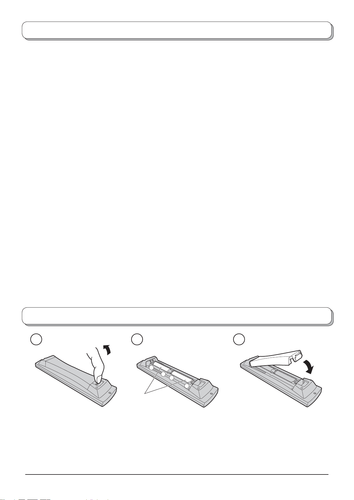
Fitting remote control batteries
321
+
+
-
“R6 (UM3)” size
Pull and hold the hook, then
open the battery cover.
• Make sure that the batteries are fi tted the correct way round.
• Do not mix old batteries with new batteries. Remove old, exhausted batteries immediately.
• Do not mix different battery types, i.e. Alkaline and Manganese or use rechargeable (Ni-Cd, Ni-MH) batteries.
Insert batteries - note correct
polarity ( + and -).
Replace the cover.
3
Page 4
Installation
Please use the apparatus only with the stands supplied or with appropriate wall mount kits.
Receiver Location
Locate for comfortable viewing. Avoid placing where sunlight or other bright light (including refl ections) will fall on the
screen.
Use of some types of fl uorescent lighting can reduce remote control transmitter range.
Adequate ventilation is essential to prevent internal component failure. Keep away from areas of excessive heat or
moisture.
Optional External Equipment
The Video/Audio connection between components can be made with shielded video and audio cables. For best
performance, Antenna cables should utilize 75 Ohm coaxial shielded wire. Cables are available from your dealer or
electronic supply store.
Before you purchase any cables, be sure you know what type of output and input connectors your various components
require. Also determine the lenght of cable you `ll need.
For optimum quality picture
When the LCD is exposed to light from outdoors or lighting fi xtures, high-contrast pictures may not be displayed clearly.
Turn off fl uorescent lamps near the LCD and place in location not exposed to outdoor light.
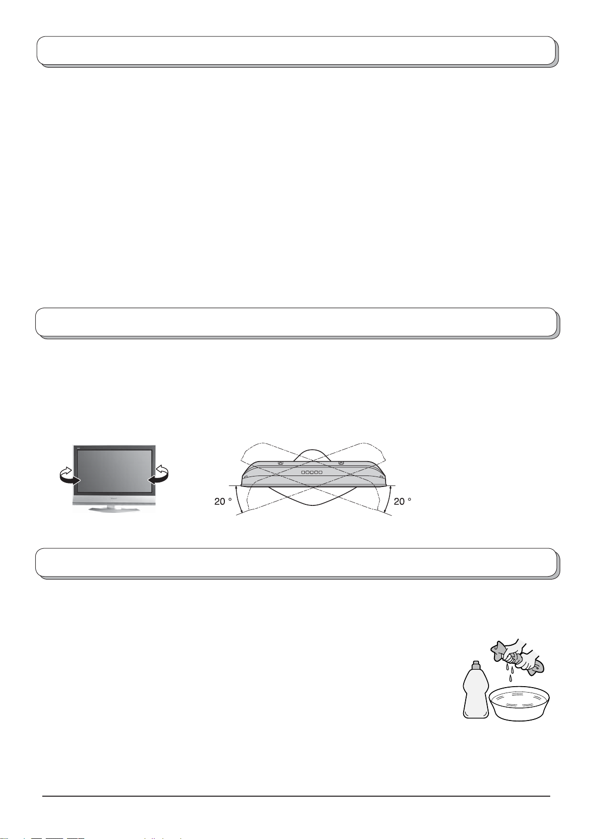
How to use the LCD stand
Adjust the LCD panel to your desired angle.
The LCD panel can be adjusted the following direction:
20° Right
20° Left
(View from the top)
Maintenance
To clean this set, wipe with a soft, dry cloth.
If the surfaces are extremely dirty, use a soft cloth dipped in soap-and-water solution or a
weak detergent solution.
• Use eyeglass cleaner to remove stubborn dirt from the LCD.
• Never use alcohol, paint thinner or benzine to clean this set.
• Before using chemically treated cloth, read the instructions that came with the cloth
carefully.
• Do not wipe the LCD with water.
Neutral
detergent
Wipe the cabinet with a soft cloth.
If the cabinet is heavily soiled, wipe with a well-wrung soft cloth dipped in neutral cleanser diluted with water.
CAUTION:
If water or similar substances get inside the monitor via the liquid crystal panel surface, a malfunction may result.
4
Page 5
Quick Start Guide
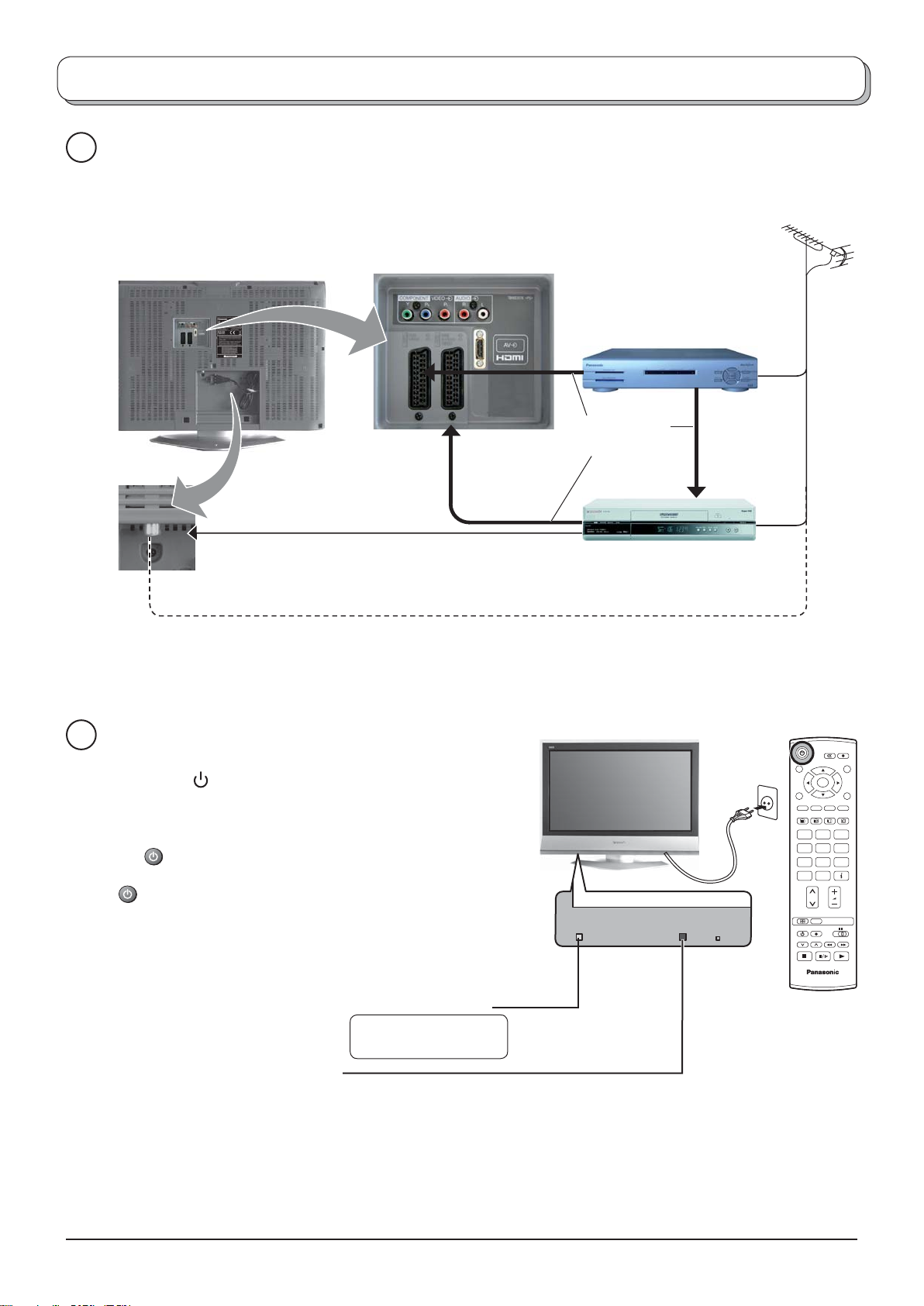
Connection and setting up options
1
Please ensure that the unit is disconnected from the mains
before attaching or disconnecting any leads.
RF cable
(Not supplied)
SET TOP BOX
Scart cables
(Not supplied)
RF cable (Not supplied)
2
Connect the mains plug to the wall sock et.
Press the [ ] switch on the TV set to turn the
set on.
To switch the TV set to Standby mode, press
the button on the remote control.
The TV set can be switched on by pressing the
button again if it was in Stand by mode.
Note:
This TV will still consume some power as long
as the mains plug is still inserted into the wall
socket.
Remote control signal sensor
VCR / DVD
Recorder
Plug in aerial and connect ancillary equipment.
Power Indicator
Standby : Red
On : No Light
OR
OK
123
456
789
C
0
N
TV
Red light indicates Standby mode.
When using remote control, this indicates the
TV has received a command.
5
Page 6
Quick Start Guide
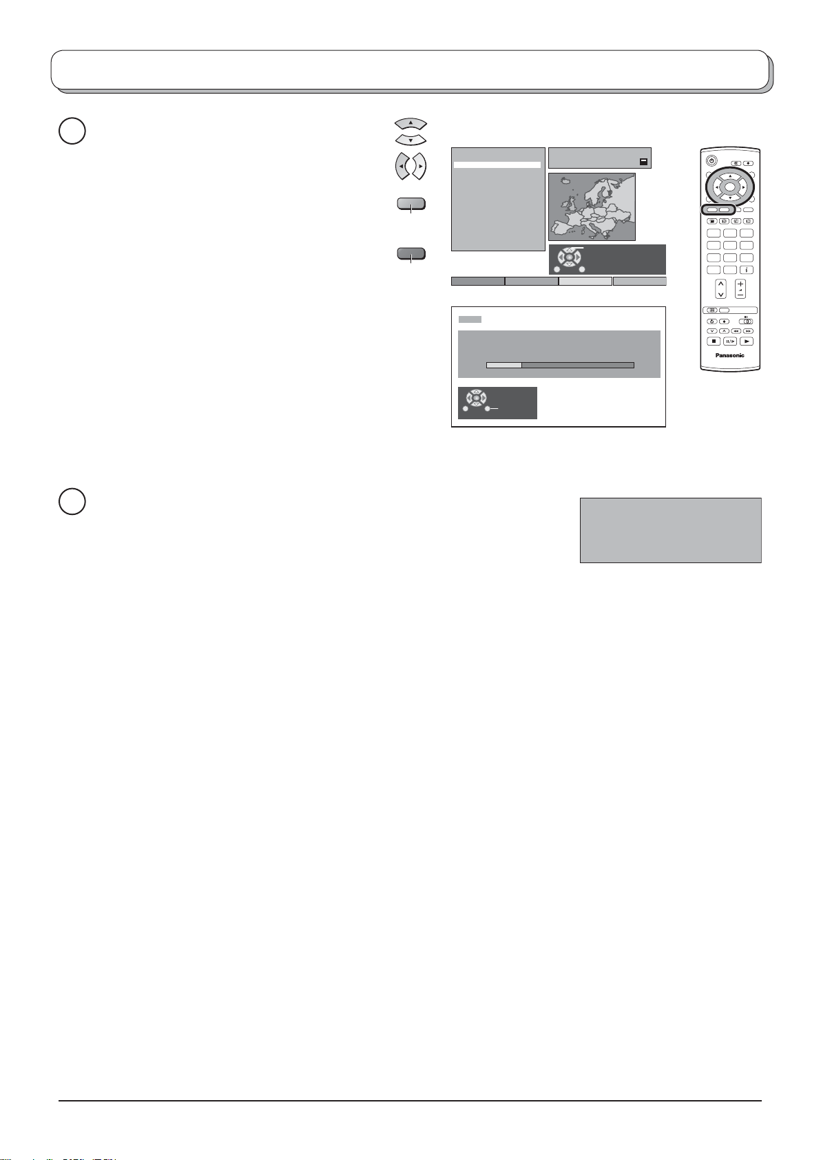
Select your country.
3
For Belgium, Switzerland and E.Eu, select
the desired language.
If you wish to perform manual tuning, press
the Green button.
See page 16.
Press the Red button to start Auto Setup.
Auto setup will begin, your stations will be
located and stored.
If a compatible recording device is connected
to the correct Scart ter mi nal, programme
data will be down load ed to the device via
Q-Link.
See page 17.
Green
Red
Land
Deutschland
Österreich
France
Italia
España
Portugal
Nederland
Danmark
Sverige
Norge
Suomi
Belgien
Schweiz
ELLADA
Polska
Česká republika
Magyarország
E.Eu
CH12
AUTO SETUP IN PROGRESS
SEARCHING : PLEASE WAIT
02 99:21 41
Exit
OSD Sprache
Deutsch
SuchlaufStart ATP Abbruch
Auswählen
OK
123
456
789
C
0
N
TV
TV to VCR or DVD Recorder Download
4
If a “Q-Link”, “NEXTVIEWLINK” or compatible recording device has been
connected to a Scart terminal before starting Step 2, programme information
will be downloaded to that device.
DOWNLOAD IN PROGRESS
PLEASE WAIT
Programme : 63
Remote control unavailable
The programme positions will be downloaded to the recording device, in the same order as stored in the TV.
See page 17.
Not all VCRs / DVD Recorders support this download of programme information, some may require to be
started manually.
Refer to the recording device’s operating instruction book.
If a recording device other than those described above has been connected, then there will be no download
operation.
Notes:
• If the recording device has not accepted download data from the TV, you may need to select the Download
option from the device’s menu system. Refer to the recording device’s operating instruction book.
• If Q-Link is not operating correctly, check the following:
The Scart cable is connected to the TV’s Scart terminal, AV1 or AV2, and correctly setup in the menu.
The Scart cable is connected to the recording device’s compatible (Q-Link, NEXTVIEWLINK or similar
technology) Scart terminal.
The Scart cable is a “fully wired” type.
• For further information on Q-Link and connecting equipment, see page 17, 25, 27.
6
Page 7
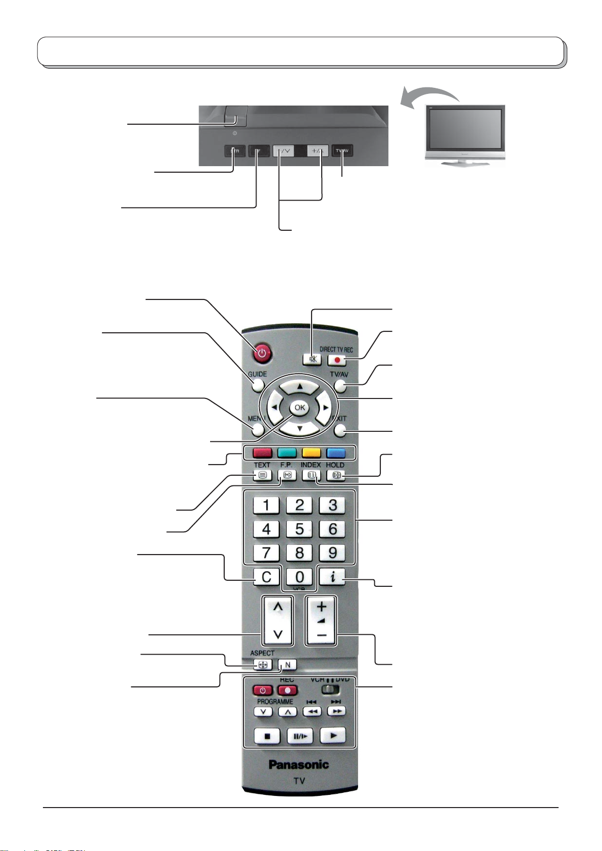
Basic controls: control panel and remote control
On / Off switch
STR (Normalization store)
Used to store tuning and other function settings.
F (Function select)
Displays the On Screen Display functions, use
repeatedly to select from the available functions -
Volume, Backlight
Sharpness, Tint (in NTSC mode), Bass, Treble,
Balance and Tuning mode.
Standby On / Off button
Switches TV On or Off (Standby mode).
, Contrast, Brightness, Colour,
Increases or decreases the programme position by one. When a
function is already displayed, press to increase or decrease the
selected function. When in Standby mode, switches TV On.
TV/AV button (see page 24)
Sound mute On / Off
GUIDE button
Displays the Programme table.
Move the cursor to choose the position,
then press the OK button to the viewing
screen.
Menu button
Press to access the Picture, Sound and
Setup menus. (see page 8-11)
Press to confi rm selections and choices.
Coloured buttons used for the selection,
navigation and operation of various
functions.
Teletext button (see page 21-23)
Text F.P. button (see page 22)
Direct channel access
During normal TV viewing or when
in the Tuning, Programme edit or
Manual tuning menus, press and then
enter channel number using the numeric
buttons.
Channel up / down button
ASPECT control button
(see page 18, 19)
DIRECT TV Record button
(see page 17)
Switch between viewing TV or AV input.
(see page 24)
Cursor buttons to make selections and
adjustments.
Exit the mode.
Text Hold / Picture Still button
(see page 22, 23)
Text Index button (see page 23)
Programme / channel change buttons (0-
9) and Teletext page buttons.
(see page 21-23)
When in Standby mode, switches TV
On.
Status button
Press to display status information for the
current Programme position, Programme
name, Channel number, MPX mode,
Receiving system and ASPECT mode.
Press again to remove the information.
Volume up / down button
N (Normalize) button
Resets all settings to their default levels.
VCR / DVD buttons
(see page 20)
7
Page 8
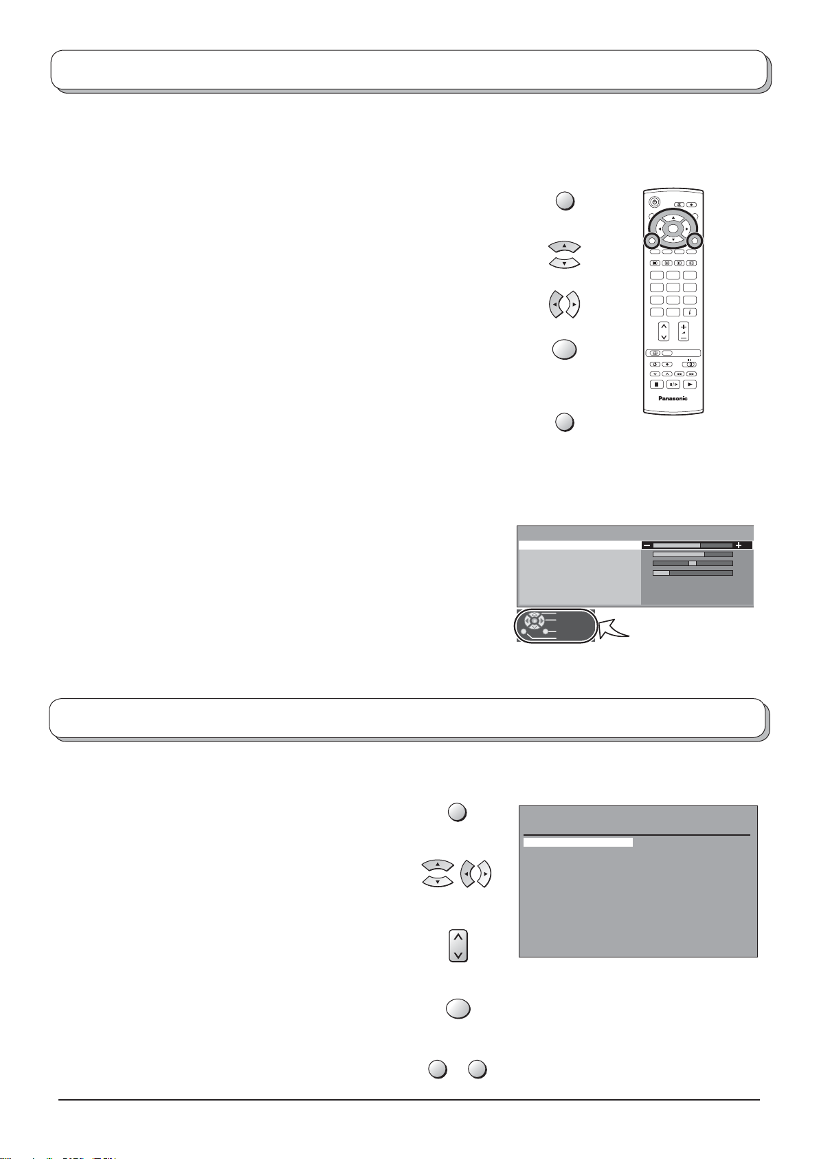
Using the On Screen Displays
Many features available on this TV can be accessed via the On Screen Display menu system. Use the remote control
as shown below to access and adjust features as desired.
The MENU button is used to open the main menus and also
to return to the previous menu.
The up and down cursor buttons are used to move the
cursor and select menus.
The left and right cursor buttons are used to access menus,
adjust levels or to select from a range of options.
The OK button is used with a number of features to store
settings after adjustments have been made or options have
been set.
The EXIT button is used to exit the menu system and re turn
to the normal viewing screen.
An On Screen Help box is displayed whenever a menu is
dis played on the TV. This Help box indicates which buttons on
the remote control are used to navigate the menu shown, see
above for descriptions of button functions.
Note:
The Help box is not shown in the menu pictures in this in struc tion
book due to space limitations.
MENU
OK
EXIT
Sound menu
Bass
Treble
Balance
Headphone volume
MPX
Mode
Ambience
Select
Adjust
Exit
Return
OK
123
456
789
C
0
N
TV
Stereo
Music
Off
ON SCREEN HELP
‘Instructions’ box
Programme guide
The programme guide shows programme list
To view a list of the stations that have been found, press
the GUIDE button on the remote control.
In this guide, use the cursor buttons to move the cursor
bar around the list.
Use the programme change button to step through the
guide page by page.
Pres the OK button to view the selected programme.
Note:
The Guide can be cleared from the screen using the
EXIT or GUIDE button.
8
GUIDE
OK
EXIT GUIDE
Programme guide
Prog . Name Chan.
VCR : CH21
Das Erste CH44
1 :
2 : ZDF CH51
3 : RTL CH41
4 : CH23
5 : CH26
6 : CH58
7 : 8 : 9 : 10 : 11 : 12 : -
Prog . Name Chan.
13 : -
14 : 15 : 16 : 17 : 18 : 19 : 20 : 21 : 22 : 23 : 24 : -
Page 9

Picture menu
Press the MENU button.
Move to choose Picture menu.
Access Picture menu.
Move to choose menu option.
Adjust chosen option or access chosen menu.
Press the EXIT button at any time to go back to watching TV.
Viewing mode The Viewing mode menu allows you to select three different
screen settings - Dynamic, Normal and Cinema. In each
Viewing mode setting, Backlight, Contrast, Brightness,
Colour, Sharpness, Tint (in NTSC only), Colour balance,
P-NR, can be adjusted and stored to suit your particular
viewing requirement. (e.g., you may require different
settings for viewing sports, fi lms, news etc.)
Viewing mode offers you up to a maximum of three
separate settings for each signal source: RF, AV1,
AV2, AV3 Component and HDMI. Changes will be
stored automatically. By analysing and processing the
incoming picture, all three modes feature automatic
enhancement.
MENU
123
456
789
C
EXIT
Main menu
Picture menu
Sound menu
Setup menu
Picture menu
Viewing mode
Backlight
Contrast
Brightness
Colour
Sharpness
Colour balance
P-NR
OK
0
N
TV
Dynamic
Normal
Auto
Backlight, Contrast, Brightness, Colour, Sharpness
Increase or decrease the levels of these options ac cord ing
to your personal preference.
Tint With an NTSC signal source connected to the TV, the
picture hue can be adjusted to suit your taste.
Colour balance Allows you to set the overall colour tone of the picture.
Choose from Cool, Normal and Warm.
P-NR Automatically reduces unwanted picture noise.
If receiving HD signal or in HDMI mode only two choices
are avaiable.
Picture menu
Viewing mode
Backlight
Contrast
Brightness
Colour
Sharpness
Colour balance
P-NR
Picture menu
Viewing mode
Backlight
Contrast
Brightness
Colour
Sharpness
Colour balance
P-NR
Dynamic
Normal
Auto
Dynamic
Normal
Auto
9
Page 10

Sound menu
Press the MENU button.
Move to choose Sound menu.
Access Sound menu.
Move to choose menu option.
Adjust chosen option or access chosen menu.
Press the EXIT button at any time to go back to watching TV.
Press the OK button after having adjusted some features to store the new
settings as the default (replacing the factory setting).
Bass Increase or decrease level to enhance or minimise lower,
deeper sound output.
Treble Increase or decrease level to enhance or minimise
sharper, higher sound output.
MENU
EXIT
OK
Main menu
Picture menu
Sound menu
Setup menu
OK
123
456
789
C
0
N
TV
Balance The levels of sound between the left and right speak ers
can be adjusted to suit your listening position.
Headphone volume Can be adjusted independently of the TV speakers so
that everyone can enjoy listening at a level com fort able
for them.
MPX Usually set to Stereo to provide the best re pro duc tion,
but if reception deteriorates or if the service is not
available then switch to Mono. Mono (M1) and (M2) can
also be selected if a mono signal is being transmitted.
Mode Sound quality can be improved when watching music
scene or drama by selecting the appropriate Music or
Speech mode.
Ambience Ambience provides a dynamic enhancer to simulate
improved spatial effects.
Switching is also possible by pressing the Ambience
button.
Sound menu
Bass
Treble
Balance
Headphone volume
MPX
Mode
Ambience
Sound menu
Bass
Treble
Balance
Headphone volume
MPX
Mode
Ambience
Sound menu
Bass
Treble
Balance
Headphone volume
MPX
Mode
Ambience
Sound menu
Bass
Treble
Balance
Headphone volume
MPX
Mode
Ambience
Stereo
Music
Off
Stereo
Music
Off
Stereo
Music
Off
Stereo
Music
Off
HDMI input Displayed during HDMI input mode.
Allows you to choose from Auto, Digital and
Analogue.
Select to fi t the input signal.
Auto : Set in normal use
Digital : HDMI cable connection
Analogue : HDMI-DVI adapter cable connection
See page 26.
10
HDMI mode
Sound menu
Bass
Treble
Balance
Headphone volume
Mode
Ambience
HDMI input Auto
Music
Off
Page 11
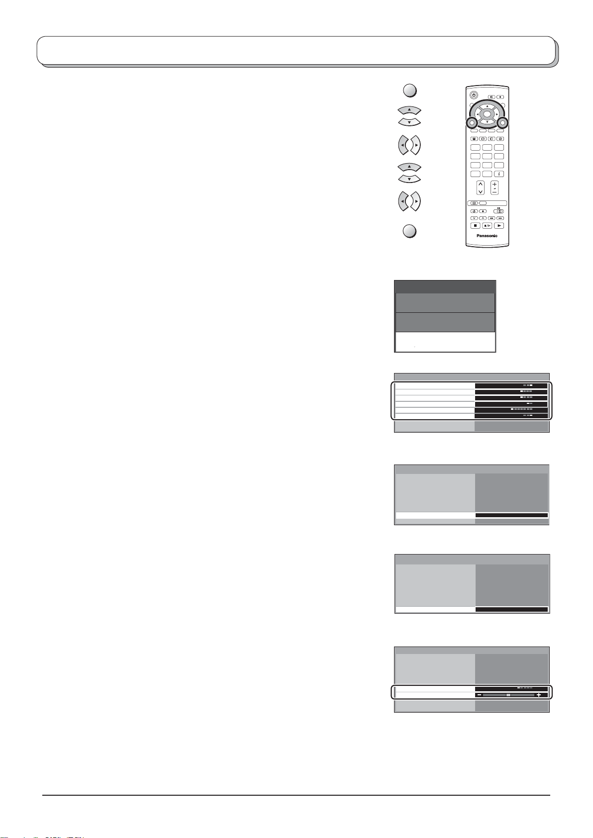
Setup menu
Press the MENU button.
Move to choose Setup menu.
Access Setup menu.
Move to choose menu option.
Adjust chosen option or access chosen menu.
Press the EXIT button at any time to go back to watching TV.
Q-Link Allows you to select which AV terminal is to be used for data
communication between this TV and a com pat i ble recording
device. Choose from Off, AV1 and AV2. See page 17.
AV1 out Offers a choice of signals to send to the AV1 Scart socket.
You can choose from the current TV programme position, the
signal en ter ing AV2 / AV3 or Monitor - the picture displayed
on screen.
HDMI and component signal inputs cannot be output to these
Scart terminals.
AV2 out Offers a choice of signals to send to the AV2 Scart socket.
You can choose from the current TV programme position, the
signal en ter ing AV1 / AV3 or Monitor - the picture displayed
on screen.
HDMI and component signal inputs cannot be output to these
Scart terminals.
Teletext Allows you to choose between TOP / FLOF or List mode.
See page 21-23.
Off timer Switches the TV off within a preset time which you can choose
from between 0 to 90 minutes in 15 minute intervals.
Text language Select character set, so that all characters needed are
availabe for text on teletext pages (e.g., cyrillic char ac ters,
etc.).
Mode Languages
West: English, French, German, Greek, Italian, Spanish,
Swedish, Turkish
East1: English, Estonian, Latvian, Rumanian, Russian,
Lithuanian, Ukrainian
East2: Czech, Hungarian, Latvian, Polish, Rumanian,
Lithuanian
Tuning menu Provides access to many other features including Programme
edit and Auto setup. See page 12-16.
OSD language When you fi rst install the TV, the On Screen Display language
is set according to your choice of country. OSD language lets
you change the language used for On Screen Displays.
Colour system During AV mode, Colour system is displayed. See page 12.
Volume
correction
During AV mode, Volume correction is displayed. You
can adjust volume level of AV mode. Volume level is
memorised.
MENU
EXIT
Main menu
Picture menu
Sound menu
Setup menu
Setup menu
Q-Link
AV1 out
AV2 out
Teletext
Off timer
Text language
Tuning menu
OSD language
Setup menu
Q-Link
AV1 out
AV2 out
Teletext
Off timer
Text language
Tuning menu
OSD language
Setup menu
Q-Link
AV1 out
AV2 out
Teletext
Off timer
Text language
Tuning menu
OSD language
AV mode
Setup menu
Q-Link
AV1 out
AV2 out
Teletext
Off timer
Colour system
Volume correction
Text language
OSD language
OK
123
456
789
C
0
N
TV
AV2
TV
TV
FLOF
Off
East 2
AV2
TV
TV
FLOF
Off
East2
Access
AV2
TV
TV
FLOF
Off
East 2
Access
AV2
TV
TV
FLOF
Off
Auto
West
11
Page 12
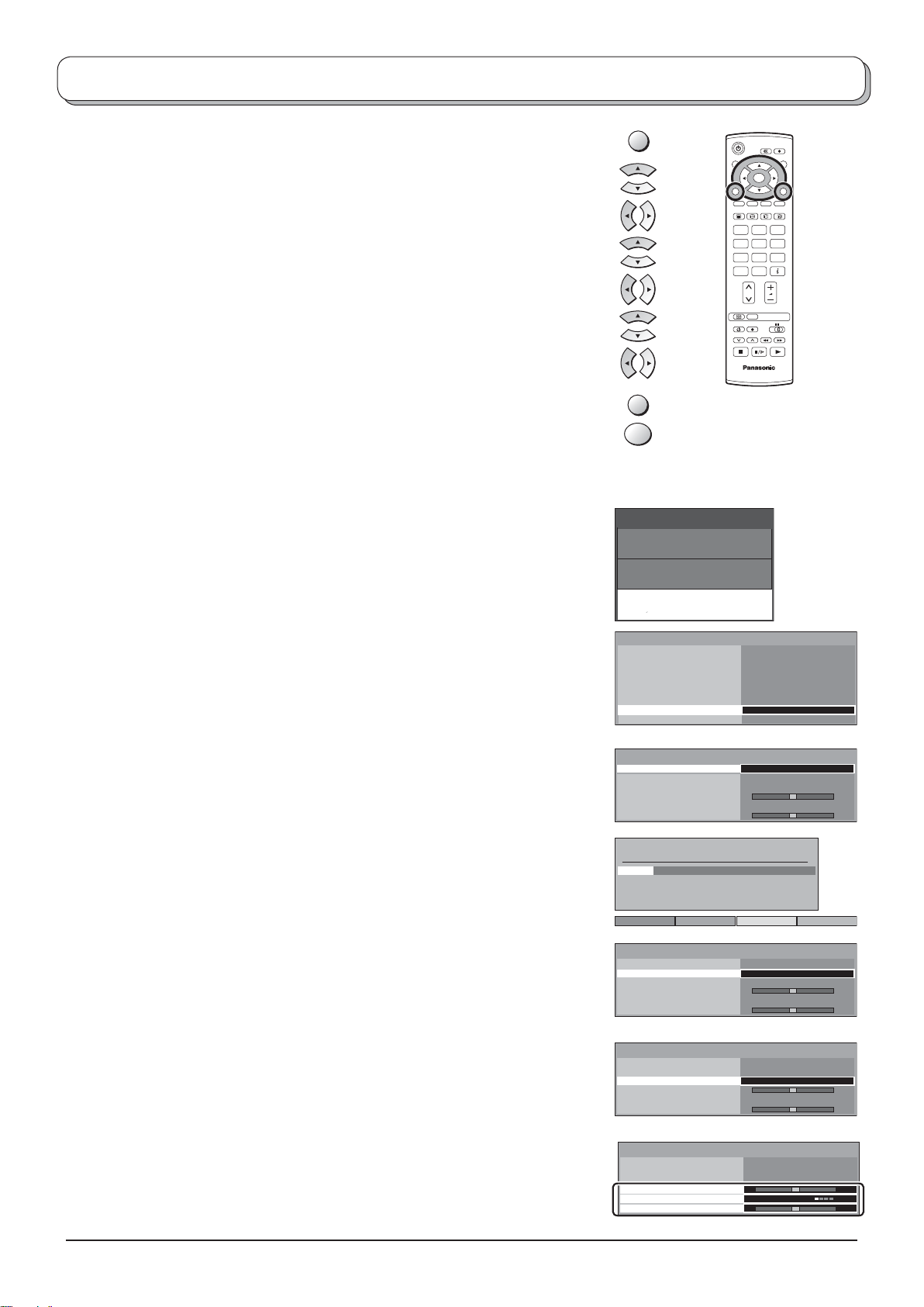
Tuning menu – overview
Press the MENU button.
Move to choose Setup menu.
Access Setup menu.
Move to choose Tuning menu.
Access Tuning menu.
Move to choose menu option.
Adjust chosen option or access chosen menu.
Press the EXIT button at any time to go back to watching TV.
Press the OK button after having adjusted some features to store
the new settings as the default (replacing the factory setting).
Programme edit Access in order to customize your programme set tings
(e.g., adding or deleting a programme position). See
page 13, 14.
MENU
EXIT
OK
Main menu
Picture menu
Sound menu
OK
123
456
789
C
0
N
TV
Auto setup Allows you to automatically retune the TV. Useful if you
move house and wish to retune your TV to the local
stations. See page 15.
Manual tuning Allows individual programme positions to be tuned
manually. See page 16.
Fine tuning Use to make small adjustments to the tuning of an individual
station (useful for example when weather conditions are
affecting reception quality of a programme).
Colour system Lets you select the correct transmission standard for the
transmission signal being received.
Volume correc. Lets you adjust the volume level of individual stations. Use
this feature if the volume level varies signifi cantly between
stations. Adjusting one station’s volume to bring it into line
with the other stations means you can avoid having to
adjust the volume each time you change channels.
Setup menu
Setup menu
Q-Link
AV1 out
AV2 out
Teletext
Off timer
Text language
Tuning menu
OSD language
Tuning menu
Programme edit
Auto setup
Manual tuning
Fine tuning
Colour system
Volume correc.
Programme edit
Prog. Chan. Name Lock Sys
1 :
CH44
2 :
CH51
3 :
CH41
4 :
CH47
5 :
CH37
Delete Add Move Download
Tuning menu
Programme edit
Auto setup
Manual tuning
Fine tuning
Colour system
Volume correc.
Tuning menu
Programme edit
Auto setup
Manual tuning
Fine tuning
Colour system
Volume correc.
ABC
XYZ
FTP
123
456
AV2
TV
TV
FLOF
Off
East2
Access
Access
Auto
Off
Off
Off
Off
Off
Access
Auto
Access
Auto
SC1
SC1
SC1
SC1
SC1
12
Tuning menu
Programme edit
Auto setup
Manual tuning
Fine tuning
Colour system
Volume correc.
-
Auto
-
+
+
Page 13
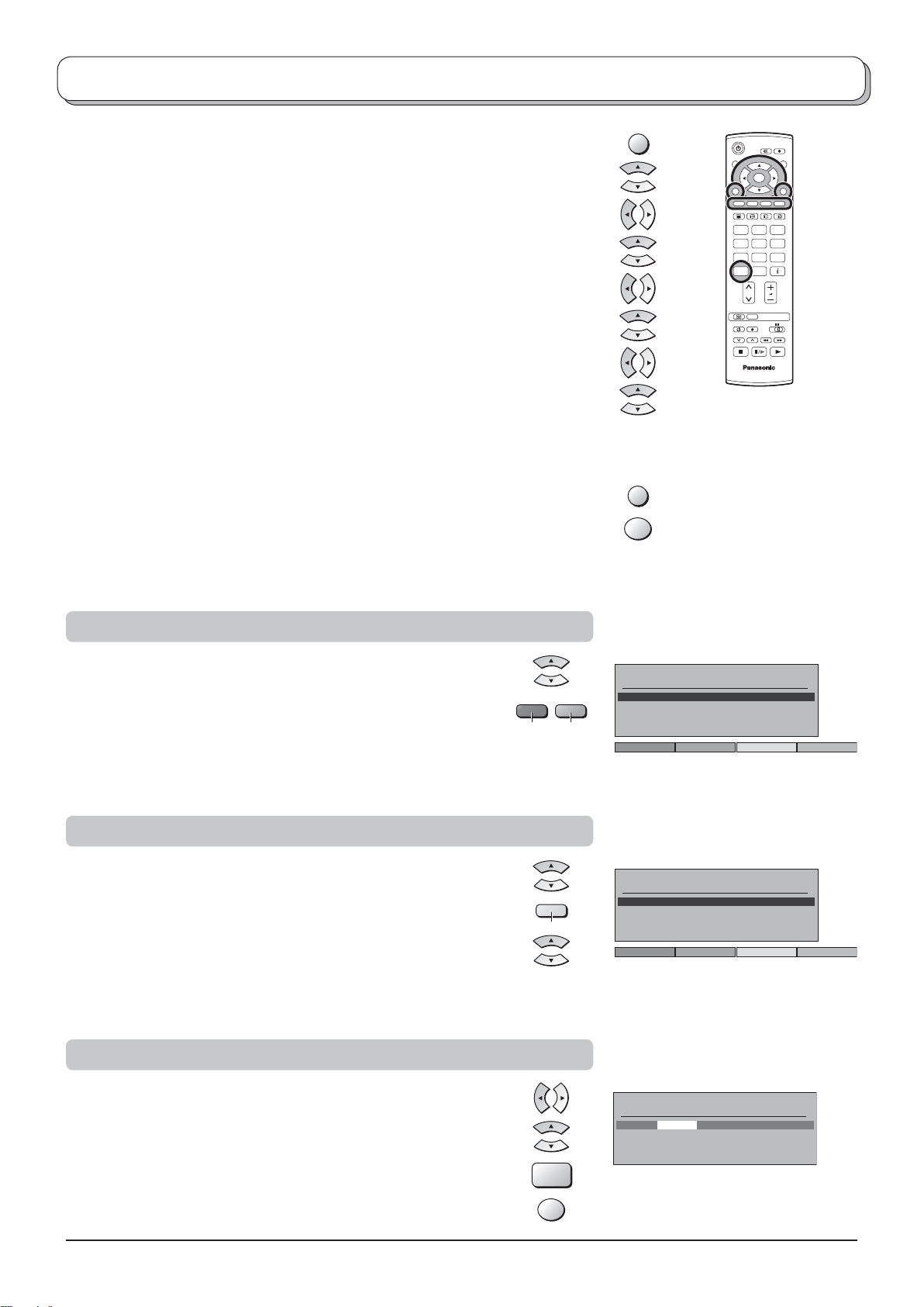
Tuning menu – Programme edit
Press the MENU button.
Move to choose Setup menu.
Access Setup menu.
Move to choose Tuning menu.
Access Tuning menu.
Move to choose Programme edit.
Access Programme edit.
Move to choose programme position (e.g., Prog. 3).
Make required change, e.g., moving a programme channel (see the
relevant procedure below).
Press the EXIT button at any time to go back to watching TV.
Press the OK button after having adjusted some features to store the
new settings.
MENU
EXIT
OK
OK
123
456
789
C
0
N
TV
Adding / deleting a programme channel
Move the cursor to the programme to be deleted or added.
Press the Green button to add a programme channel to the
programme position, or the Red button to delete one.
Press the same button again to confi rm your decision.
Moving a programme channel
Move the cursor to the programme to be moved.
Press the Yellow button.
Choose the new position for the programme channel.
Press the Yellow button again to confi rm your decision.
Tuning a programme channel
Yellow
Programme edit
Prog. Chan. Name Lock Sys
1 :
CH44
2 :
CH51
3 :
CH41
4 :
GreenRed
CH47
5 :
CH37
Add Cancel
Programme edit
Prog. Chan. Name Lock Sys
1 :
CH44
2 :
CH51
3 :
CH41
4 :
CH47
5 :
CH37
ABC
XYZ
FTP
123
456
ABC
XYZ
FTP
123
456
Confirm Cancel
Off
Off
Off
Off
Off
Off
Off
Off
Off
Off
SC1
SC1
SC1
SC1
SC1
SC1
SC1
SC1
SC1
SC1
Move to the Chan. column.
Increase or decrease the programme channel number (you will
see the TV retune to the new number as you change it) or use the
C button for Direct Channel Ac cess. See page 7.
Press the OK button to store this change.
C
OK
Programme edit
Prog. Chan. Name Lock Sys
1 :
CH44
ABC
Off
2 :
3 :
4 :
5 :
CH51
CH41
CH47
CH37
XYZ
FTP
123
456
Off
Off
Off
Off
SC1
SC1
SC1
SC1
SC1
13
Page 14
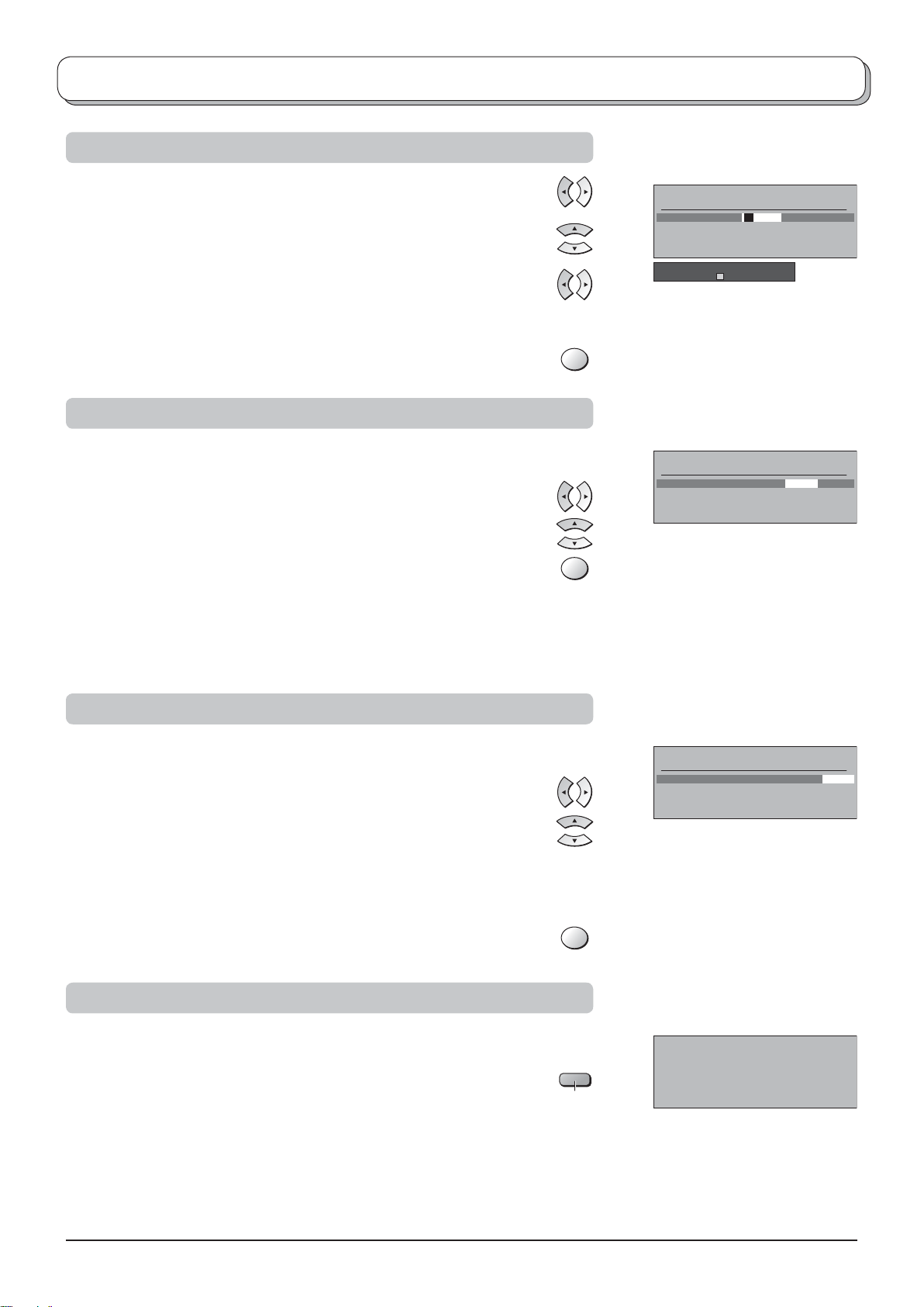
Tuning menu – Programme edit
Renaming a programme channel
Move to the Name column.
Choose the new character. The box at the bottom of the screen shows
the character currently selected.
Move to the next character position.
Continue until renaming is done.
Press the OK button to store the new name.
Locking a programme channel
You may wish to lock a programme channel to prevent ac cess to it.
Move to the Lock column.
Choose between Lock On or Lock Off.
Press the OK button to store the new setting.
Note:
When a programme position is locked, Direct Channel Access
using the C and numeric buttons on the remote control is not
available.
OK
OK
Programme edit
Prog.
Chan. Name Lock Sys
1 :
CH44
2 :
CH51
3 :
CH41
4 :
CH47
5 :
CH37
ABCDEFGHIJKLMNOPQRST
UVWXYZ+
-
. 0123456789
Programme edit
Prog. Chan. Name Lock Sys
1 :
CH44
2 :
CH51
3 :
CH41
4 :
CH47
5 :
CH37
XYZ
FTP
123
456
ABC
XYZ
FTP
123
456
Off
Off
Off
Off
Off
Off
Off
Off
Off
Off
SC1
SC1
SC1
SC1
SC1
SC1
SC1
SC1
SC1
SC1
Changing the sound system for a channel
You can change the sound system used for a programme channel.
Move to the Sys column.
Choose the required sound system:
SC1 : PAL B, G / SECAM B, G
SC2 : PAL I
SC3 : PAL D, K / SECAM D, K
F : SECAM L / L’
Press the OK button to store the new setting.
Copying programme information to a recording device
You can copy programme information to a compatible re cord ing device
connected to AV1 / AV2. See page 25 for con nec tion information.
Press the Blue button.
Programme data will now be sent to the recording device(s). This
might take a few seconds, depending on the number of stations stored.
If the message “Feature not available” ap pears on the screen, the
television is unable to send the programme information to the recording
device(s). See the device’s instruction book for further information.
OK
Blue
Programme edit
Prog. Chan. Name Lock Sys
1 :
CH44
ABC
Off
2 :
CH51
3 :
4 :
5 :
DOWNLOAD IN PROGRESS
Remote control unavailable
XYZ
CH41
FTP
CH47
123
CH37
456
PLEASE WAIT
Programme : 63
Off
Off
Off
Off
SC1
SC1
SC1
SC1
SC1
Note:
This is not available when you choose Q-Link Off in Setup menu.
14
Page 15
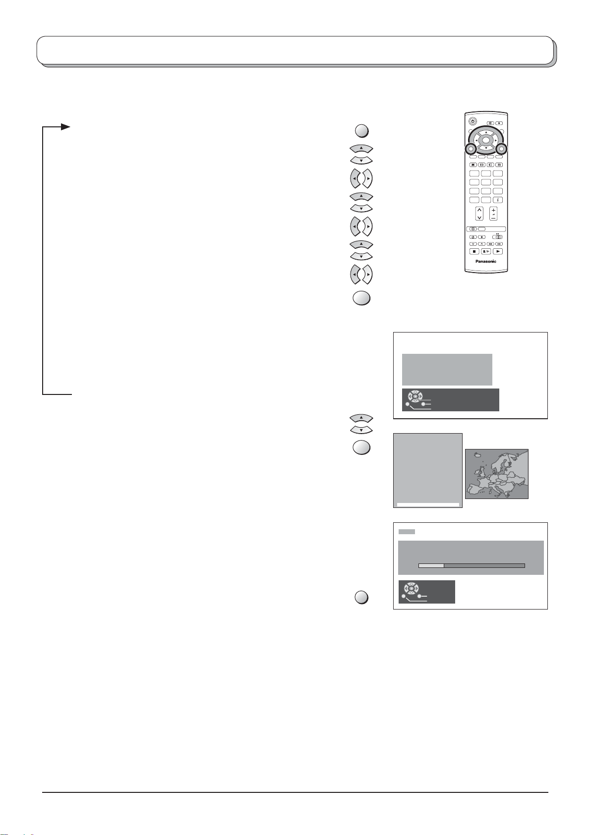
Tuning menu – Auto setup
Auto setup automatically retunes your TV. This feature is useful if, e.g., you move house and wish to retune your TV
to receive the local stations.
Press the MENU button.
MENU
Move to choose Setup menu.
Access Setup menu.
Move to choose Tuning menu.
Access Tuning menu.
Move to choose Auto setup.
Access Auto setup.
Press to confi rm start.
OK
Notes:
• If you proceed with the next step all tuning data will be erased
(all stations and their programme positions stored in your TV’s
memory will be wiped out so the new settings can be stored).
• If you exit the procedure after this point and before Auto setup is
complete, no station information will be stored. Restart and complete
the Auto setup procedure so that the TV is retuned.
Select your country.
Press to start Auto setup.
OK
The TV will search for, locate, store and then sort into
order your local stations.
If compatible recording device is connected via the AV1 /
AV2
terminal, programme data will be sent to the device
via Q-Link. See page 17.
Once this operation is completed the TV will display the
programme now stored on programme position 1.
Press the EXIT button at any time to go back to watching
EXIT
TV (please read the Notes in the above procedure).
123
456
789
C
WARNING
All current tuning
data will be erased
Start ATP
Exit
Return
Country
Deutschland
Österreich
France
Italia
España
Portugal
Nederland
Danmark
Sverige
Norge
Suomi
Belgium
Schweiz
ELLADA
Polska
Česká republika
Magyarország
E.Eu
CH12
AUTO SETUP IN PROGRESS
SEARCHING : PLEASE WAIT
02 99 :21 41
Exit
Return
OK
0
N
TV
15
Page 16
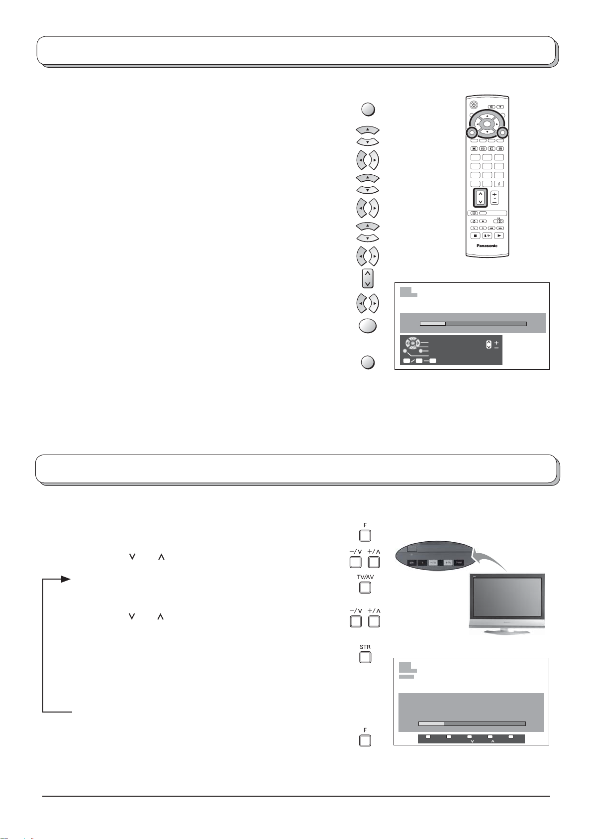
Tuning menu – Manual tuning
It is possible to retune individual programme positions:
Press the MENU button.
Move to choose Setup menu.
Access Setup menu.
Move to choose Tuning menu.
Access Tuning menu.
Move to choose Manual tuning.
Access Manual tuning.
Select the programme position to be tuned.
Press repeatedly until required station is found.
When the desired station is found, press the OK button to store.
The programme position will fl ash.
Press the EXIT button at any time to go back to watching TV.
MENU
OK
EXIT
1
CH12
Manual tuning
02 99:21 41
Search down/up
Store
Exit
Return
C
0 9
Direct entry
OK
123
456
789
C
0
N
TV
Note:
If your VCR is connected to this TV by an RF cable only, choose programme position “0” to tune to the VCR
signals.
Manual tuning (via control panel)
It is also possible to use the control panel buttons on the top of your TV to tune individual programme positions:
Press the F button until Tuning mode is reached.
Press the –/ or +/ button to access Tuning mode.
Press the TV/AV button to move between Change
programme, Search and Change TV system.
Press the –/ or +/ button to change programme position
or start search.
When the desired station is found, press the STR button
to store.
The programme position will fl ash.
1
CH12
SC3
16
Repeat above procedure to tune additional programme
positions.
Press the F button at any time to go back to watch ing TV.
Manual tuning
-
, + : Search
TV / AV : Move cursor
STR : To store
F : To exit
02 99:21 41
STR F- / + / TV / AV
Page 17
Q-Link
Q-Link allows the television to communicate with a compatible VCR or DVD Recorder.
For Q-Link communication to work, the TV must be connected to a recording device with the “Q-Link”, “NEXTVIEWLINK”,
“DATA LOGIC”, “Easy Link”, “Megalogic” or “SMARTLINK” logo using a “fully wired” Scart cable between the AV1 /
AV2 terminal of the television and the appropriate terminal on your VCR or DVD Recorder.
For connection to the appropriate Scart terminal on the recording device, refer to the device’s instruction book.
When using a “NEXTVIEWLINK” device the main features possible are the following:
Preset Download
This allows the programme order from the TV to be downloaded to the recording device, helping to ensure that correct
recordings are made; there are several ways to perform this operation:
1. During installation as explained in the “Quick Start Guide” on page 5, 6.
2. When Auto setup is started from within the Tuning menu. See page 12.
3. Preset download started from the recording device, refer to the device’s instruction book.
What You See Is What You Record (DIRECT TV RECORDING)
This will allow the immediate recording of the programme currently shown on the TV, by the recording
device attached to the Scart terminal, which can be chosen using “Q-Link”. See page 11.
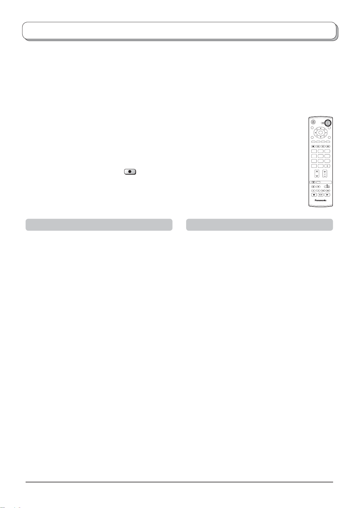
Press the DIRECT TV REC button.
DIRECT TV REC
If the recording device is in Standby mode with usable recording media inserted, it will automatically
switch on when you press the DIRECT TV REC button.
If a “Q-Link” device is connected, a message will appear on the TV screen showing what is being recorded,
or if it is not possible to record. Some “Q-Link” compatible devices will only display the message when
on the VCR programme position “0” or in AV mode. Refer to the device’s instruction book.
OK
123
456
789
C
0
N
TV
Recording in progress No recording - Check tape or Disc
The recording device is recording the programme signal
from its own tuner. If you wish you can switch off the TV
and leave the device recording in the normal way.
Additionally, when using a “Q-Link” device the main features possible are the following:
The following features are only available from the device connected to the Scart terminal selected using “Q-Link”.
See page 11.
TV / Recording device Auto Power On
If you insert pre-recorded media into the recording device and press the Play button whilst the TV is in Standby mode,
the TV will automatically switch on and select the correct AV input so that you can view the content.
Recording device Auto Power Standby
When the TV is switched into Standby mode, the recording device will also switch into Standby mode if there is no
media inserted, or if there is media inserted and the device is in Rewind or Stop mode. If a VCR is rewinding a tape,
it will not switch into Standby mode until rewinding has fi nished.
Recording device Image View On
If the TV is in Standby mode and the recording device sends a menu to be displayed on the TV screen (e.g., Main
menu), the TV will automatically switch On and the menu will be displayed.
This TV will also communicate with other recording device’s that bear the following logos:
• “DATA LOGIC” (a trademark of Metz Corporation) • “Megalogic” (a trademark of Grundig Corporation)
• “Easy Link” (a trademark of Philips Corporation) • “SMARTLINK” (a trademark of Sony Corporation)
Important Note:
Some recording devices may not support all or some of the above functions. Refer to the instruction book for the
device.
If Q-Link functions do not work, check the connection and ensure that the scart lead is a fully-wired type.
The tape or disc may have been “write protected”,
miss ing or may be damaged. The device may already be
re cord ing. Refer to the device’s instruction book.
To share tuning information
To ensure correct recordings are made, the television and VCR (DVD/R) should share tuning information see page 14.
• Whenever the Auto setup (ATP) function is used, tuning data will be downloaded to the VCR (DVD/R).
To turn off Q-Link communication
If you do not wish to use the Q-Link feature, go to the Setup menu and set the Q-Link option to "Off". See page 11.
17
Page 18
A
Aspect Controls
The Widescreen TV will allow you to enjoy viewing the picture at its optimum size and aspect, including widescreen
cinema format pictures.
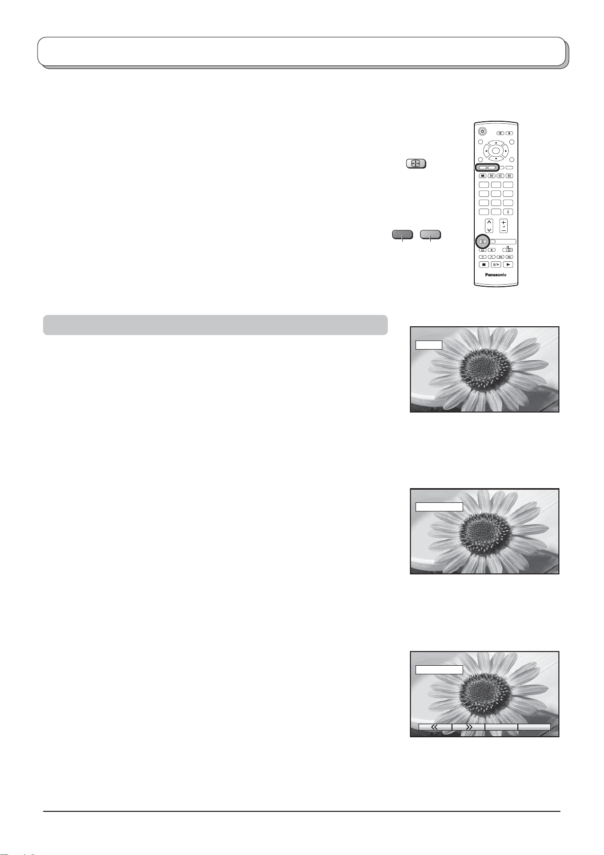
Press the ASPECT button repeatedly to move through the nine aspect
options:
Auto aspect, 16:9, 14:9, Just, 4:3, 4:3 Full (HD signal), Zoom1,
Zoom2 and Zoom3
OR
Press the ASPECT button. Whilst the on screen selector keys are
displayed, use the Red or Green buttons to move in either direction
through the nine aspect options.
Auto aspect
Auto aspect determines the best aspect ra tio to use to fi ll your screen. It does
this using a four step process to determine if the picture being viewed is a
widescreen picture.
If Auto aspect detects a widescreen signal it switches into the ap pro pri ate
widescreen mode. If Auto aspect does not detect a widescreen signal then
this advanced TV set enhances the picture for optimum viewing pleasure.
The text shown on the screen indicates how Auto aspect de ter mined which
ratio to use:
SPECT
GreenRed
WIDE
OK
123
456
789
C
0
N
TV
“WIDE” ap pears in the top left of
the screen, Auto aspect switch es
to the ap pro pri ate 16:9 or 14:9
widescreen ratio.
Auto aspect switches to the appropriate widescreen ratio.
“Auto aspect” appears in the top left of the screen if black stripes above and
below the picture are detected.
Auto aspect chooses the best ratio and expands the picture to fi ll the screen.
This process can take several minutes, depending on the darkness of the
picture.
You may prefer to manually select one of the other aspect options available
to view the picture.
Notes:
• If, in Auto aspect mode, you experience problems with the screen display
size when playing back widescreen format recordings from your VCR then
it is possible that the tracking control of your VCR requires adjustment (your
VCR instruction book will contain adjustment details).
• The widescreen aspect ratios of different fi lms and programmes can vary.
If these are wider than a standard 16:9 aspect picture then a black band may
be visible at the top and bottom of the screen.
• “WIDE” will appear in the top left corner of the screen and picture aspect
changes accordingly in any aspect modes, if a widescreen identifi cation signal
(WSS) is detected or a control signal is found through a Scart terminal.
• Automatic aspect ratio adjustment by WSS signal is not available for
progressive and high defi nition component signals input.
Auto aspect
“Auto aspect” appears in the top
left of the screen. The best ratio is
chosen and the picture expanded
to fi ll the screen.
Auto aspect
Press the ASPECT button, then
use the Red or Green buttons to
move in either direction through
the eight aspect options.
18
Page 19
Aspect Controls
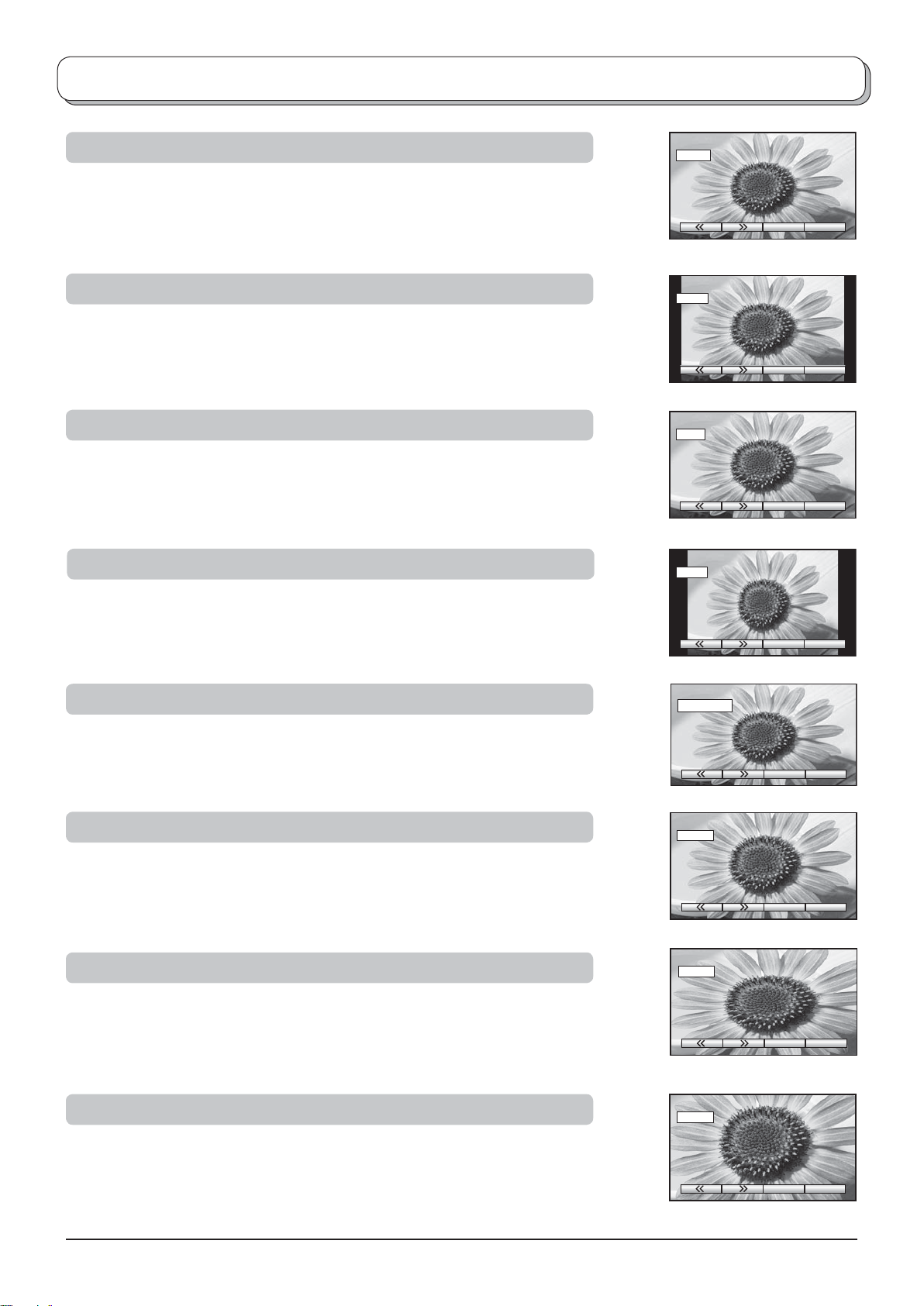
16 : 9
16:9 will display a true 16:9 (anamorphic) picture with no aspect distortions.
14 : 9
14:9 will display a 14:9 picture at its standard 14:9 size without any
stretching.
Just
Use Just when you wish to expand a 4:3 picture to fi ll the whole screen (rather than
watching a programme with black stripes down the left and right sides of the picture).
The 4:3 picture will be stretched horizontally so that the image fi lls the screen, this is
done in such a way that the stretching is only obvious at the left and right edges of the
screen.
4 : 3
16 : 9
16 : 9
14 : 9
14 : 9
Just
Just
4 : 3
4:3 will display a 4:3 picture at its standard 4:3 size with no aspect
distortions.
4 : 3 Full
4:3 will display a 4:3 picture enlarged horizontally to fi t the screen.
Zoom1
Zoom1 will display 16:9 letterbox or 4:3 pictures with no aspect distortions.
Zoom2
Zoom2 will display 16:9 anamorphic letterbox pictures as a full screen display
with no aspect distortions.
4 : 3
4 : 3 Full
4 : 3 Full
Zoom1
Zoom1
Zoom2
Zoom3
Zoom3 will display 21:9 letterbox pictures as a full screen display with no
aspect distortions.
16:9 will display the picture at its maximum size but with slight stretching.
Zoom2
Zoom3
Zoom3
19
Page 20
VCR / DVD operation
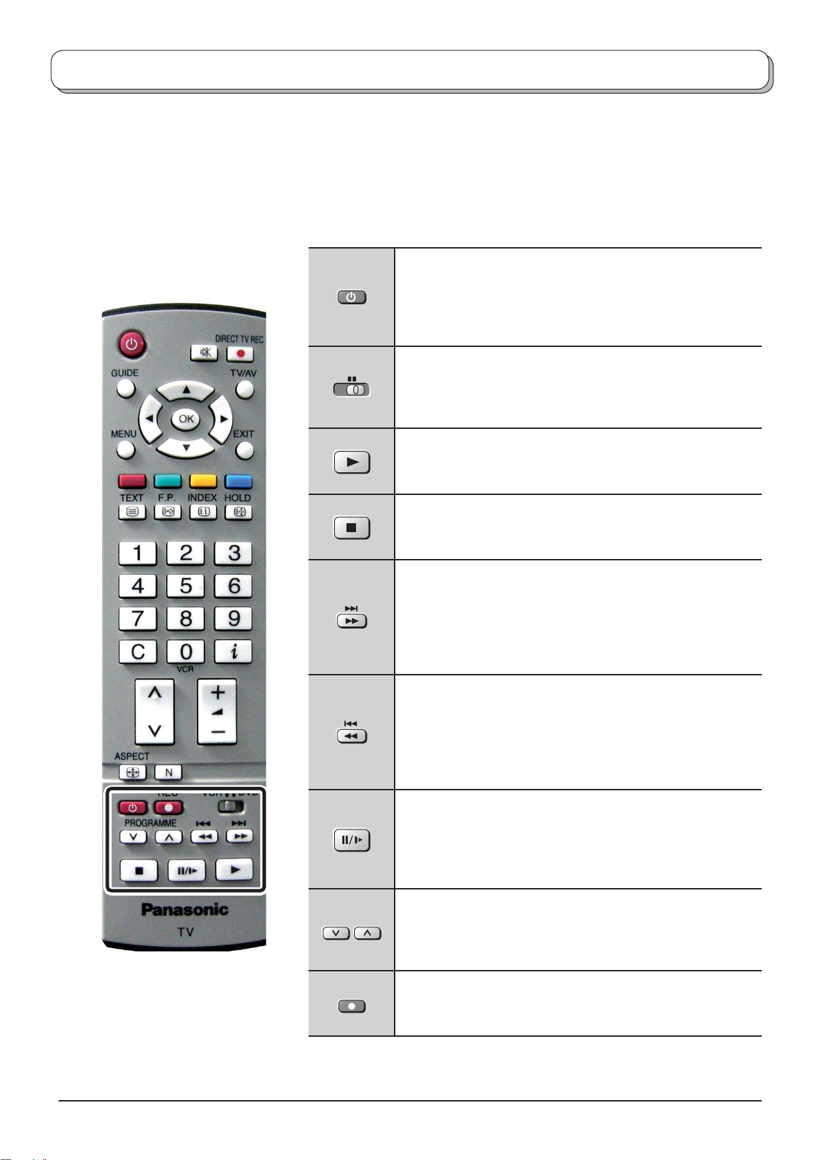
The Remote Control is capable of operating some functions of selected Panasonic VCRs and DVD (Digital Versatile
Disc) equipment. Some VCR and DVD equipment have different functions, so to ensure compatibility please refer to
the equipment’s instruction book or consult your dealer for details.
Standby
Press to switch the VCR, DVD or DVD recorder to Standby
mode.
Press again to switch back on.
VCR DVD
VCR / DVD switch
Use this switch to select whether controls operate the DVD
equipment or VCR.
Play
Press to playback the tape or DVD.
Stop
Press to stop the tape or DVD.
Skip / Fast Forward / Cue
VCR: Press to fast forward the tape. In Play mode, press
to view the picture rapidly forward (Cue).
DVD/R: Press to skip to the next track or title.
Press and hold to search forward.
Skip / Rewind / Review
VCR: Press to rewind the tape. In Play mode, press to
view the picture rapidly in reverse (Review).
DVD/R: Press to skip to the previous track or title.
Press and hold to search backward.
20
PROGRAMME
REC
Pause / Still
Press in Play mode, the picture will pause.
Press again to restart play.
DVD/R: Press and hold for slow-motion play.
Programme Up / Down
Press to increase or decrease the programme position by
one.
Record
Press this button to start recording.
Page 21
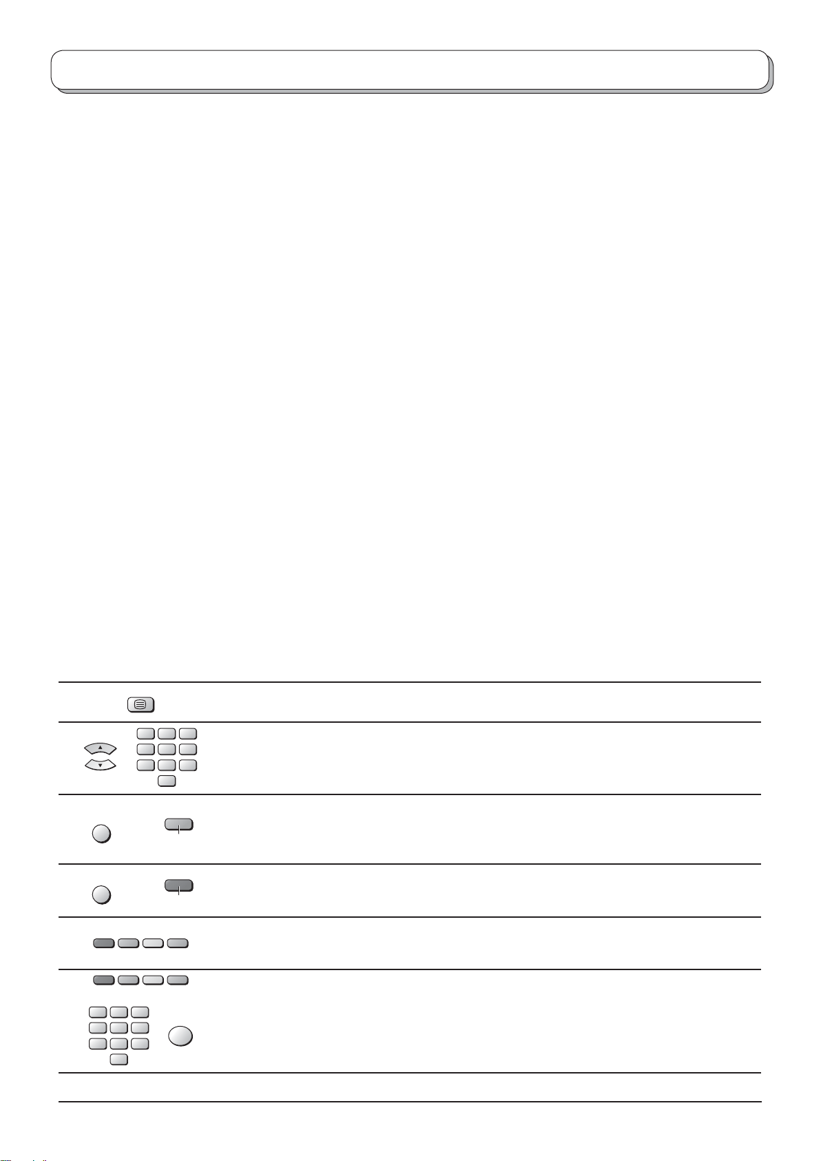
Teletext operation
• Teletext features may vary depending on the Broadcasting Companies and is only available if the channel selected
is transmitting Teletext.
• Pressing the MENU button thrice whilst in Teletext operation will display the contrast function with a cyan bar, press
the left and right cursor buttons to alter the setting as required.
• Pressing the MENU button whilst in Teletext operation will display special function options at the bottom of the
screen.
• Pressing the Volume up / down button whilst in Teletext operation will display the volume function with a green bar,
press the volume up / down button to alter the setting as required.
What is List mode ?
In List mode, four differently coloured page numbers are situated at the bottom of the screen. Each of these numbers
can be altered and stored in the TV’s memory.
What is FLOF (FASTEXT) mode?
In TOP / FLOF mode, four differently coloured subjects are situated at the bottom of the display. To access more
information about one of these subjects, press the appropriately coloured button. This facility enables fast access to
information on the subjects shown.
What is TOP Teletext?
TOP Teletext makes the task of selecting the desired Teletext pages easier and shorter. In fact page access time is
almost instantaneous, just press the button and the page appears.
How does it work?
TOP Teletext uses the four coloured buttons, Red, Green, Yellow and Blue to select the following information.
• To move between subject blocks (SPORT for example) use the Blue button. Within this SPORT topic it is possible to
select different groups such as Tennis, Football, Baseball etc, by using the Yellowbutton. When the last group within
the block is reached, the yellowbuttonmoves to the next block.
• The Green button will select the next available page UP.
• The Red button will select the next available page DOWN.
What are the advantages?
• Page selection at the touch of a single button.
• Easy to use step by step selection of the topical subject.
• Reduction of waiting time.
• If a non existent page number is entered, a question mark will appear at the bottom of the screen.
• Page status line at the bottom of the screen so you always know which button will take you to the information
required.
MENU
MENU
TEXT
123
456
789
0
VCR
Green
Red
TV / Teletext mode
Press the TEXT button to switch between the current programme and teletext.
Page Selection
Pages can be selected in two ways:
a. Press the Up / Down cursor buttons to increase or decrease the page number by one.
b. By entering the page number, using 0 - 9 on the remote control.
Full / Top / Bottom
Press the MENU button to display special functions, followed by the Green button.
Press the Green button again to expand the BOTTOM half.
Press again to return to normal (FULL) size.
Reveal
Press the MENU button to display special functions, followed by the Red button to reveal
hidden words e.g., quiz page answers. Press again to hide.
Red / Green / Yellow / Blue buttons
In TOP / FLOF mode they correspond to the differently coloured subjects.
In List mode they correspond to the differently coloured page numbers.
123
456
789
0
VCR
OK
List Store
In List mode the four page numbers can be altered (programme positions 1 - 25 only).
To do this, press one of the four coloured buttons and enter the new page number.
Press and hold the OK button, the page numbers will change to white indicating that the
page is stored.
21
Page 22
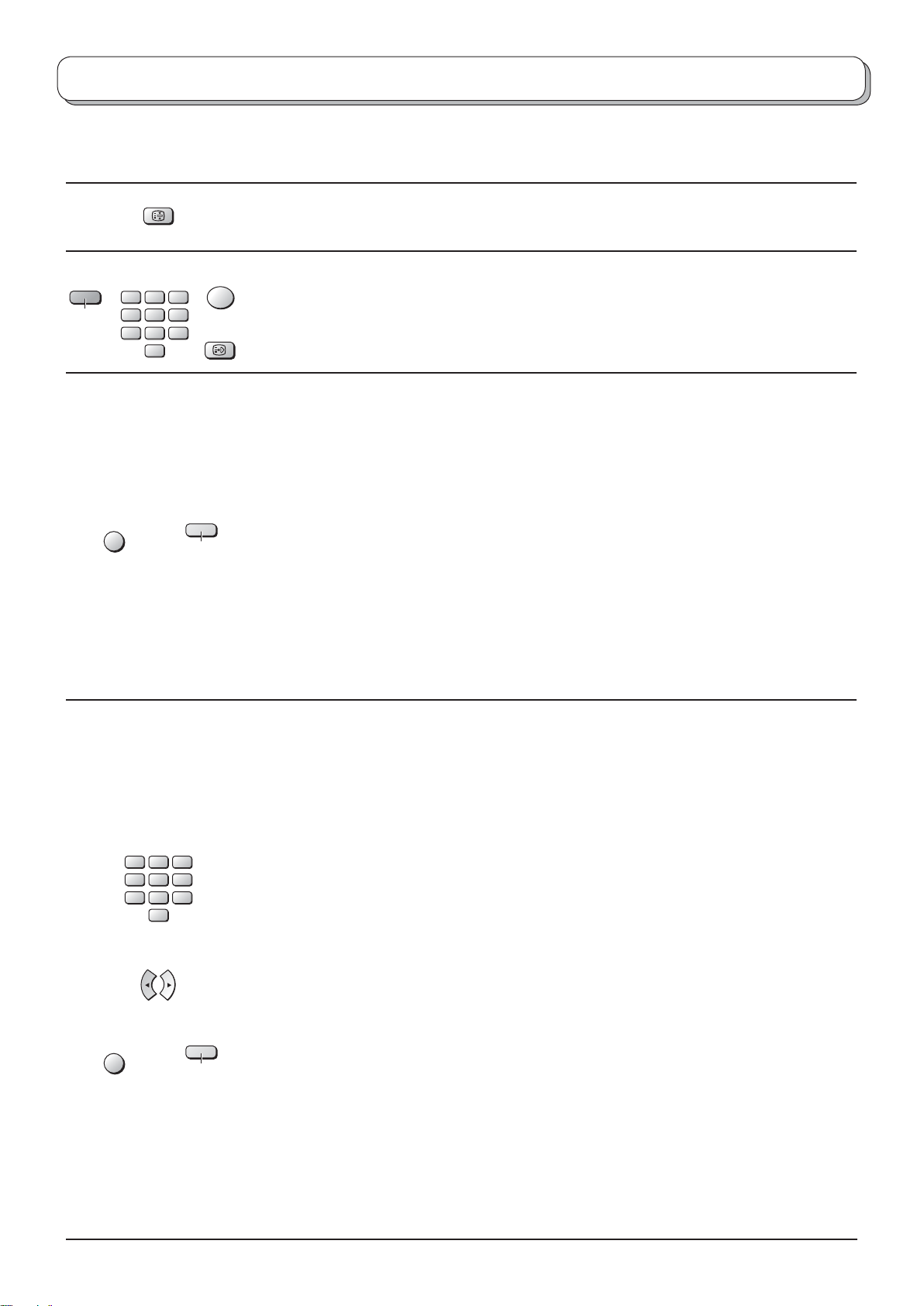
Teletext operation
It is not possible to change the programme position when in News fl ash, Update or Sub Coded Page Access
operation.
Blue
MENU
HOLD
123
456
789
0
VCR
Yellow
HOLD
To hold the Teletext page when viewing multi-page information.
Press again to return to automatic page update.
Favourite Page (F.P.)
Stores a favourite page in memory for instant recall. To store such a page, the TV must be
OK
in List mode, and the programme position must be from 1 - 25.
Press the Blue button, select the page number, then press and hold the OK button. The
F. P.
page number is now stored.
Press F.P. to recall this page.
Update Display
Press the MENU button to display special functions, followed by the Yellow button to view
the TV picture whilst searching for a Teletext page (this is not necessary in Picture and text
mode, as the picture is displayed on the left of the screen). When found, the screen will
display the page number at the top left. Press the Yellow button to view the page.
Press the TEXT button again to return to normal TV operation.
News Flash
When a news fl ash page has been selected, press the MENU, Yellow buttons, to view the
TV picture. When an update is received, the page number will be displayed on screen.
Press the Yellow button to display the News Flash.
Press the TEXT button to return to normal TV operation.
Update
Press the MENU, Yellow buttons to see the update of information on certain pages.
When an update is received, the page number will be displayed at the top left of the
screen.
Press the Yellow button to view the page.
Press the TEXT button to return to normal TV operation.
MENU
123
456
789
0
VCR
Yellow
Accessing sub pages
When Teletext information exceeds one page, it may take some time for the automatic
changing of the sub pages to reach the sub page you require. As each sub page is found
its number is displayed at the top of the page so that you may select it; as more sub pages
are picked up, the display at the top of the page changes, so that you are always offered
the most recently transmitted selection of sub pages.
In Teletext operation, use the following procedure to access sub pages:
If the sub page you want to look at is not yet available, press the MENU button (to display
special functions) followed by the Yellow button to view the TV picture whilst waiting for
more sub pages to be found. The sub pages found will be displayed across the top of the
screen.
When the sub page you are waiting for is available press the Yellow button to return to
viewing the Teletext pages, then use the left and right cursor buttons to select the sub
page of your choice.
The maximum number for sub page that can be entered is restricted to 79 by
broadcasters.
Notes:
• If you do not want to display the on screen selector keys on the TV picture whilst waiting
for a sub page to be found, press the MENU button to clear the keys from the screen.
Press again to redisplay the keys.
• If you have cleared the special function keys from the screen and then used the left and
right cursor buttons to select a sub page, whilst still viewing the TV picture, you must
press the MENU button then the Yellow button to display the Teletext page again.
• If the top of the page indicates that sub pages are being transmitted but the page displayed
never changes, then the ‘sub page number’ is there to show the page contents have been
updated, there are no sub pages.
22
Page 23
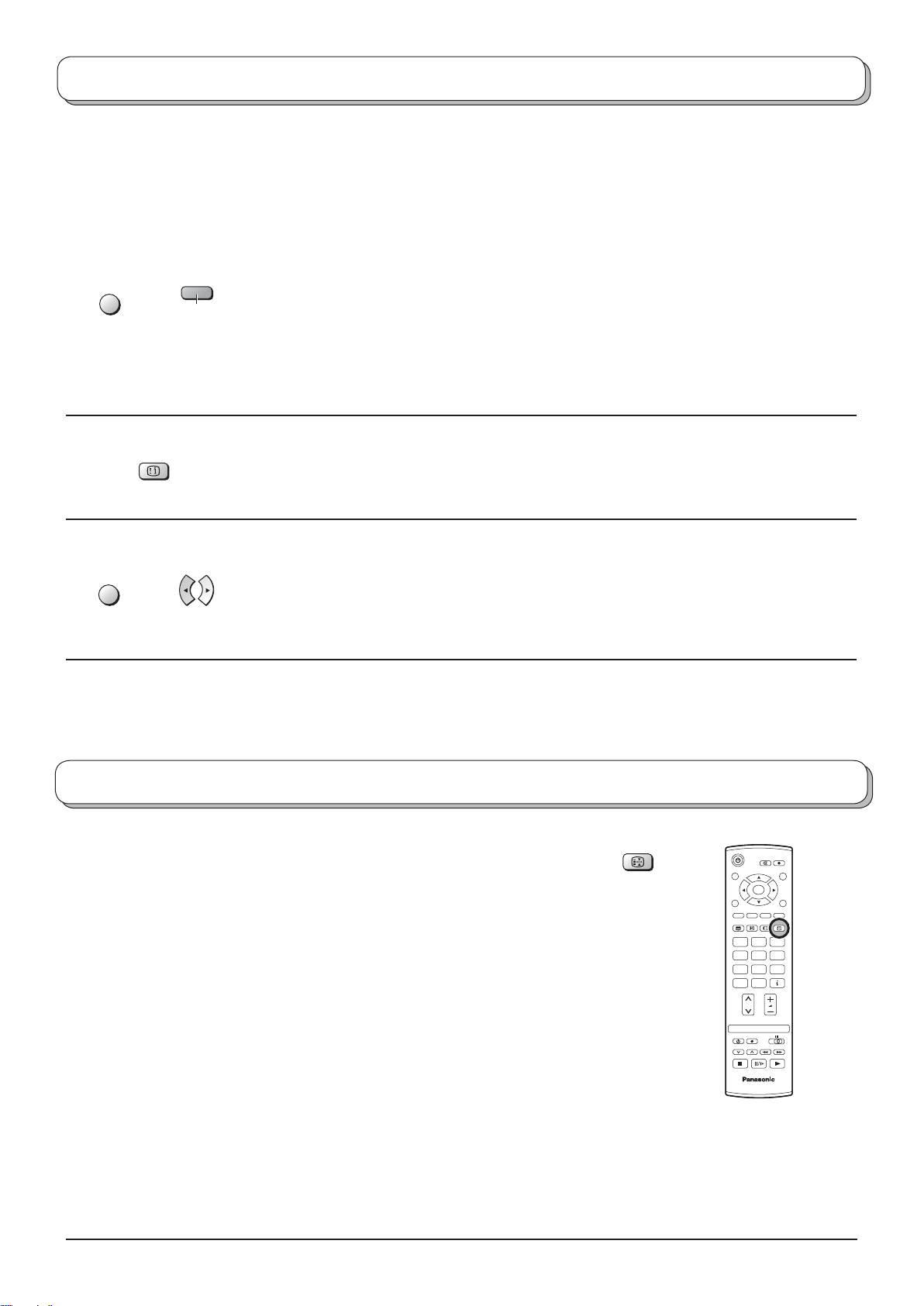
Teletext operation
Alternatively, if you know which sub page you require, press the MENU button (to display
special functions) followed by the Blue button; T**** will be displayed where the page number
is normally found.
Enter desired sub page number before the T**** disappears.
MENU
INDEX
Blue
e.g., to select page 6 enter 0, 0, 0 and 6.
Press the Yellow button to view the TV picture whilst waiting for more sub pages to be found.
The sub pages found will be displayed across the top of the screen.
When the page is available, press the Yellow button to view the page. Regardless of how
many pages are found, pressing the Yellow button will take you to the sub page which you
requested.
Press the TEXT button to return to normal TV operation.
INDEX
When in TOP / FLOF operation
Press the INDEX button to return to the main index page.
Depending on the way information is transmitted, this may have to be pressed more than
once to return to the main index page.
Picture and text
Press the MENU button twice to display special functions, followed by the left or right cursor
MENU
button to select Picture and text On or Off.
Picture and text mode lets you see the current programme and a page of teletext side by
side. Whilst using this feature, the remote control affects the teletext page; if you wish to
make changes to the programme viewed press the TEXT button to return to watching the
programme on its own then make the desired changes.
Still
Press the HOLD button to freeze the picture.
Press again to return to watching the current programme.
(Not when viewing Component and HDMI inputs.)
HOLD
OK
123
456
789
C
0
N
TV
23
Page 24
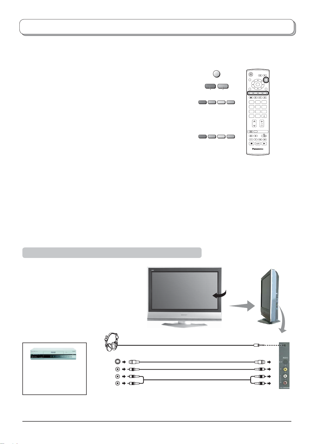
Connections
It is possible to connect a variety of additional equipment to this TV. The following pages detail how to connect external
equipment to the side and rear of the TV.
Once your equipment is connected, use the following procedure to view the input:
Press the TV/AV button.
TV/AV
Whilst the on screen selector keys are displayed, select the page by
pressing the Red or Blue button and then press coloured buttons to
Red Blue
OK
select the AV source you wish to view.
Red button : AV1 Video, Scart terminal / Back
Green button : AV2 Video, S-Video Scart terminal
Yellow button : AV3 Video, S-Video terminals /
123
456
789
C
0
Component terminal
Blue button : Next / HDMI
The on screen selector keys that appear clear after a few seconds. If you
N
want to select an input when the keys are not shown, press the colour
keys once more and the keys will reappear.
TV
Notes:
• You can also select an AV source using the TV/AV button on the top panel of the TV.
Press the TV/AV button repeatedly until you reach the AV source you wish to view.
• When in A V or HDMI mode a reduced number of options are available in the Picture, Sound and Setup menus
(e.g., in the Setup menu there is no Tuning menu option).
• This television may automatically switch over to the AV mode if the connected device sends a switch signal to
the SCART cable connector. In this case, the "EC" will be displayed in the left top corner of the screen and the
signal from the AV equipment (for the RGB signal the "EC/RGB" will be displayed). The picture received will
remain the same when the TV programme is changed.
• You may switch back to the television by pressing button TV/AV or by disconneting the AV device.
• If the external devices have selectable aspect ratio, please choose 16:9.
How to connect the Headphones / AV3 terminals
(Optional)
Connect the S-VIDEO or VIDEO terminal.
(M3 plug)
S-Video
OUT
VCR / S-VIDEO VCR
DVD PLAYER
CAMCORDER /
S-VIDEO CAMCORDER
Video
OUT
Audio
OUT
L
R
Notes:
• The volume level of the headphones can be adjusted by selecting “Headphone volume” from the Sound menu.
• Additional equipment and cables shown are not supplied with this TV set.
S-VIDEO
VIDEO
AUDIO
24
Page 25
Connections
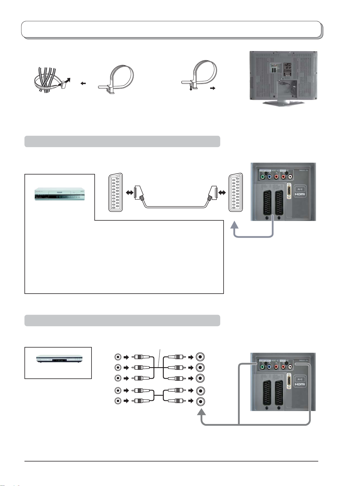
To bundle the cables with the clamper
To tighten: To loosen:
Pull
PullKeep the
knob pressed.
Note: Do not put the RF cable and the mains lead together to avoid noise.
How to connect the AV1 / 2 Scart terminals
AV1:
VCR
Q-Link COMPATIBLE VCR
SET TOP BOX
DVD PLAYER
DVD RECORDER
Q-Link COMPATIBLE DVD RECORDER
CAMCORDER
GAME CONSOLE / COMPUTER (RGB)
AV2:
VCR / S-VIDEO VCR
Q-Link COMPATIBLE VCR
SET TOP BOX
DVD PLAYER
DVD RECORDER
Q-Link COMPATIBLE DVD RECORDER
CAMCORDER / S-VIDEO CAMCORDER
GAME CONSOLE / COMPUTER (RGB)
AV1 /2
How to connect the Component Input terminals
This terminal accepts progressive or non-progressive signals format, as well as
high defi nition 750(720)/50p, 750(720)/60p, 1125(1080)/50i and 1125(1080)/60i.
Y
Y, P B, PR
B
P
DVD PLAYER
OUT
AUDIO
OUT
PR
L
R
Notes:
• Additional equipment and cables shown are not supplied with this TV set.
• Do not connect a computer with TTL output (5V) to this set.
• For Scart terminal wiring and applicable component signals information see page 27.
Y
B
P
PR
L
R
25
Page 26
Connections
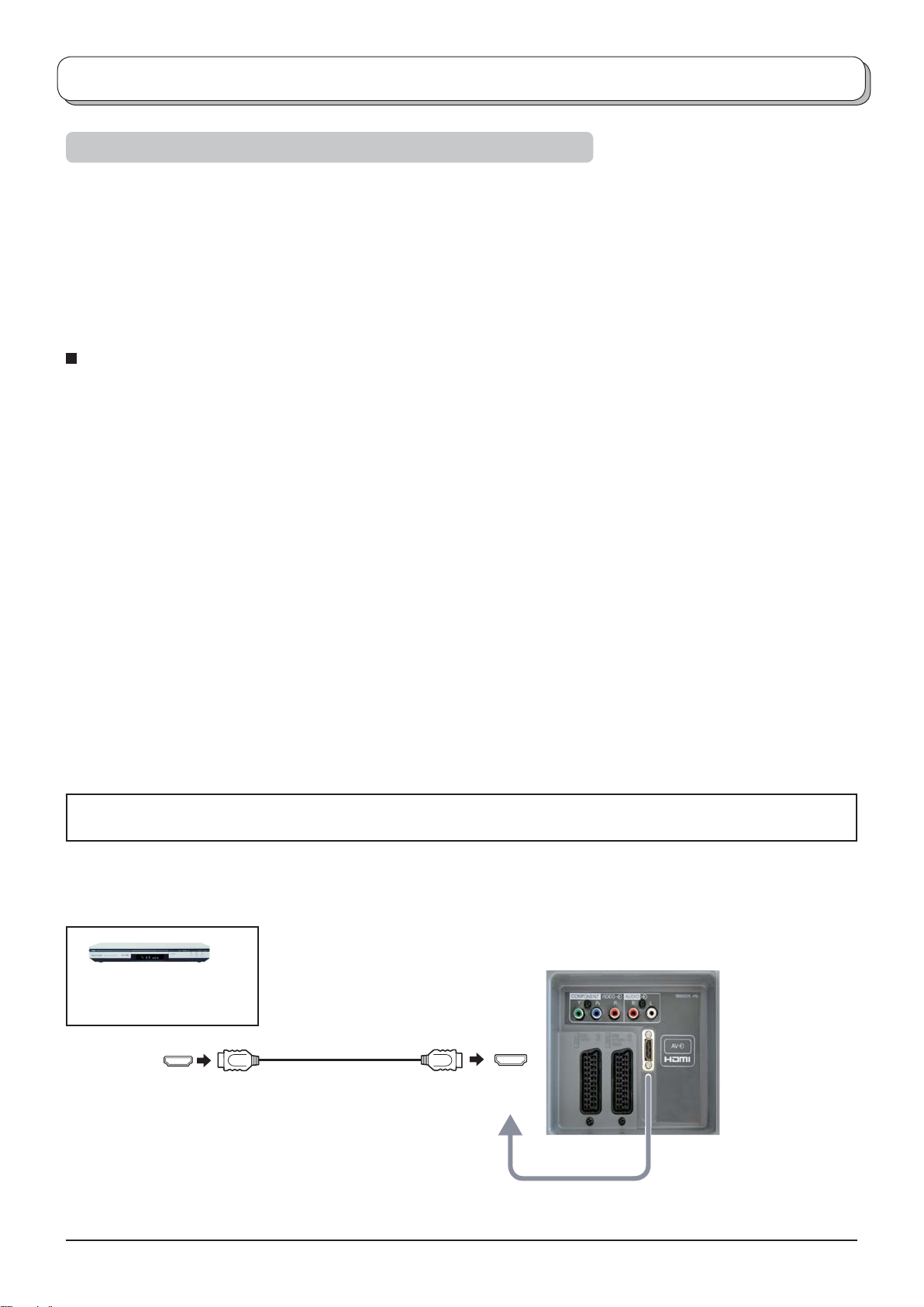
How to connect the HDMI Input terminal
HDMI (High Defi nition Multi media Interface) is the fi rst all-digital consumer electronics A/V interface that supports
uncompressed standard. The HDMI input supports both video and audio digital information.
1
An HDMI-compliant device
to the HDMI input terminal.
Compatible sampling frequency of AUDIO signal through HDMI : 48 kHz / 44.1 kHz / 32 kHz
Notes:
• If the external device has DVI output only, use a DVI to HDMI adapter cable
• Connect the audio cables to the AUDIO IN terminals when using a DVI to HDMI adapter cable.
• Audio settings can be made on the "HDMI input" menu screen. See page 10.
• This HDMI connector is Type A.
• An equipment having no digital output terminal may be connected to the input terminal of either "Component", "S-
Video", or "Scart" to receive analogue signals.
• The HDMI input terminal can be used with only the following image signals: 480i, 480p, 576i, 576p, 720p and 1080i.
Match the output setting of the digital equipment.
• This input terminal is not intended for use with computers.
• Non-HDMI-compliant cables cannot be utilized. It is recommended that you use Panasonic’s HDMI cable.
• 720p/1080i signals will be re-formatted to view on your display.
• If the external devices have selectable aspect ratio, please choose 16:9.
• For applicable HDMI signal information see page 27.
∗
, such as a Set Top Box or DVD player with HDMI or DVI output terminal can be connected
2
∗
to connect to the HDMI terminal.
∗1. HDMI-compliant device is that has the HDMI Logo on it.
∗2. HDMI-DVI adapter cable: Consult your consumer electronics dealer for availability.
SET TOP BOX
DVD PLAYER
HDMI
OUT
HDMI IN
26
Page 27
Input signal that can be displayed
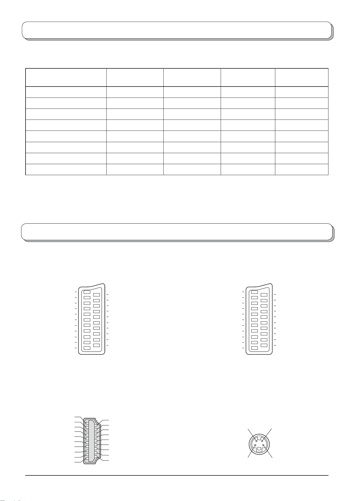
Applicable input signal for Component (Y, PB, PR) and HDMI (∗ Mark)
Signal name
Horizontal
frequency (kHz)
525 (480) / 60i 15.73 59.94
525 (480) / 60p 31.47 59.94
625 (576) / 50i 15.63 50.00
625 (576) / 50p 31.25 50.00
750 (720) / 60p 45.00 60.00
750 (720) / 50p 37.50 50.00
1125 (1080) / 60i 33.75 60.00
1125 (1080) / 50i 28.13 50.00
Vertical
frequency (Hz)
Component HDMI
∗∗
∗∗
∗∗
∗∗
∗∗
∗∗
∗∗
∗∗
Notes:
• Signals other than above may not be displayed properly.
Scart, S-video and HDMI terminals information
AV1 Scart terminal (RGB, VIDEO, Q-Link)
Socket Earth
CVBS out (video)
CVBS earth
Red in
Red earth
Green in
Green earth
Blue in
Blue earth
Audio out (L)
Audio out (R)
21
19
17
15
13
11
9
7
5
3
1
CVBS in (video)
20
RGB status earth
18
Status RGB
16
Earth
14
--
12
Q-Link data
10
Status CVBS
8
Audio in (L)
6
Audio earth
4
Audio in (R)
2
Suitable inputs for AV1 include
RGB (Red / Green / Blue).
HDMI terminal
Hot Plug Detect 19
DDC / CEC Ground 17
SCL 15
CEC 13
TMDS Clock Shield 11
TMDS Data 0- 9
TMDS Data 0+ 7
TMDS Data 1 Shield 5
TMDS Data 2- 3
TMDS Data 2+ 1
18 +5V Power
16 SDA
14
Reserved (in cable but N.C. on device)
12 TMDS Clock 10 TMDS Clock +
8 TMDS Data 0 Shield
6 TMDS Data 14 TMDS Data 1+
2 TMDS Data 2 Shield
AV2 Scart terminal
(RGB, VIDEO, S-VIDEO, Q-Link)
Socket Earth
CVBS out (video)
CVBS earth
Red in / S.C. - in
Red earth
Green in
Green earth
Blue in
Blue earth
Audio out (L)
Audio out (R)
Suitable inputs for AV2 include RGB
(Red / Green / Blue).
AV2 - Pins 15 and 20 are dependent
on AV2 S-VHS / VIDEO switching.
21
19
17
15
13
11
CVBS in (video)
20
RGB status earth
18
Status RGB
16
Earth
14
--
12
Q-Link data
9
7
5
3
1
10
Status CVBS
8
Audio in (L)
6
Audio earth
4
Audio in (R)
2
AV3 S-VIDEO 4 pin terminal
Chrominance in Luminance in
Chrominance earth Luminance earth
27
Page 28
Troubleshooting
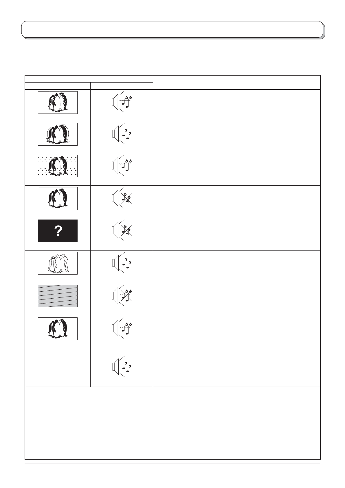
If there is a problem with your TV please refer to the table below to determine the symptoms, then carry out the
suggested check. If this does not solve the problem, please contact your local Panasonic dealer, quoting the model
number and serial number (both found on the rear of the TV).
Symptoms
Picture Sound
Snowy Picture
Multiple Images
Interference
Normal Picture
No Picture
Normal Sound
Noisy Sound
Noisy Sound
No Sound
No Sound
Checks
Aerial location, direction or connection
Aerial location, direction or connection
Electrical appliances
Cars / Motorcycles
Fluorescent lights
Switch on P-NR in Picture menu to reduce picture noise.
Volume level
Sound mute switched on.
TV set to AV mode.
Not plugged into AC outlet.
Not switched on.
Picture / Sound controls set at minimum levels.
Check if in Standby mode.
No Colour
Poor or Distorted Picture
Normal Picture
There may be red spots,
blue spots and green
spots on the screen.
Poor Video.
(Snow noise, no picture, picture runs, etc.)
H
D
M
Poor Audio.
I
Normal Sound
Weak or No Sound
Weak or Distorted
Normal Sound
Colour controls set at minimum levels.
Retune Channel (s).
Sound reception may have deteriorated.
Switch MPX setting (Sound menu) to Off until reception improves.
Sound
This is a characteristic of liquid crystal panels and is not a problem. The
liquid crystal panel is built with very high precision technology giving you
fi ne picture details. Occasionally, a few non-active pixels may appear on
the screen as a fi xed point of blue, green, or red.
Please note this does not affect the performance of your LCD.
HDMI cable is not connected securely.
Turn the power supply of the TV and connected equipment off then turn on.
Check compatibility of input signal from the connected equipment.
The connected equipment must be EIA/CEA-861/861B compliant.
Change the audio setting of the connected equipment to L.PCM.
Check the setting of HDMI input in Sound menu.
If the problem is due to the digital audio connection, change to the
analogue audio connection.
The error message appears. Please consult an Authorized Service Center.
28
Page 29
Specifi cations
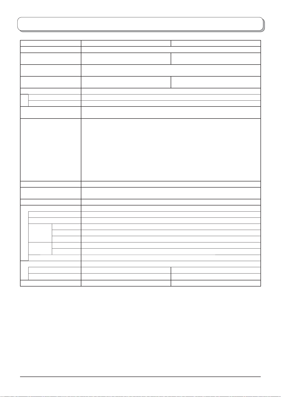
TX-26LE60F TX-32LE60F
Power Source AC 220-240 V, 50 Hz
Power Consumption
LCD
Screen Size
(
Visible Diagonal)
Sound
Audio Output
Headphones
Scanning format
Receiving Systems /
Band name
Aerial - Rear
Operating Conditions
Teletext Pages 200
Connection Terminals
AV1 (Scart connecter)
AV2 (Scart connecter)
AV3 VIDEO
S-VIDEO
AUDIO L - R
COMPONENT
HDMI
Dimensions ( W × H × D )
Including TV Stand
TV Set Only
Weight
VIDEO Y, P B, PR
AUDIO L - R
480i(60Hz), 480p(60Hz), 576i(50Hz), 576p(50Hz), 720p(50Hz), 720p(60Hz), 1080i(50Hz),
1080i(60Hz)
PAL B, G, SECAM B, G SECAM L / L’
VHF E2 - E12 VHF H1 - H2 (ITALY)
VHF A - H (ITALY) UHF E21 - E69
CATV (S01 - S05) CATV S1 - S10 (M1 - M10)
CATV S11 - S20 (U1 - U10) CATV S21 - S41 (Hyperband)
PAL D, K, SECAM D, K
VHF R1 - R2 VHF R3 - R5
VHF R6 - R12 UHF E21 - E69
PAL 525/60 Playback of NTSC tape from some PAL Video re cord ers (VCR)
M.NTSC Playback from M. NTSC Video recorders (VCR)
NTSC (AV input only) Playback from NTSC Video recorders (VCR)
UHF / VHF
Temperature : 5 °C - 35 °C
Humidity : 5 % - 90 % RH (non-condensing)
21 Pin terminal (Audio/Video in, Audio/Video out, RGB in, Q-Link)
21 Pin terminal (Audio/Video in, Audio/Video out, RGB in, S-Video in, Q-Link)
RCA PIN Type × 1
Mini DIN 4-pin
RCA PIN Type × 2
RCA PIN Type × 2
TYPE A Connector
Average use : 104 W
Standby condition : 1 W
Wide XGA (1366 × 768 pixels)
16:9 aspect ratio LCD panel
66 cm 80 cm
2 x 8 W RMS, 8 Ω
M3 (3.5 mm) Jack × 1
657 mm × 525 mm × 301 mm 791 mm × 615 mm × 301 mm
657 mm × 473 mm × 107 mm 791 mm × 563 mm × 107 mm
14 kg Net 17,5 kg Net
Average use : 117 W
Standby condition : 1 W
Note:
• Design and Specifi cations are subject to change without notice. Weight and Dimensions shown are approximate.
• HDMI, the HDMI Logo and High-Defi nition Multimedia Interface are trademarks or registered trademarks of HDMI
Licensing LLC.
29
Page 30

Page 31

Page 32
Information on Disposal for Users of Waste Electrical & Electronic Equipment
(private households)
This symbol on the products and/or accompanying documents means that used electrical and
electronic products should not be mixed with general household waste.
For proper treatment, recovery and recycling, please take these products to designated
collection points, where they will be accepted on a free of charge basis. Alternatively, in some
countries you may be able to return your products to your local retailer upon the purchase of
an equivalent new product.
Disposing of this product correctly will help to save valuable resources and prevent any
potential negative effects on human health and the environment which could otherwise arise from inappropriate
waste handling. Please contact your local authority for further details of your nearest designated collection point.
Penalties may be applicable for incorrect disposal of this waste, in accordance with national legislation.
For business users in the European Union
If you wish to discard electrical and electronic equipment, please contact your dealer or supplier for further
information.
Information on Disposal in other Countries outside the European Union
This symbol is only valid in the European Union.
If you wish to discard this product, please contact your local authorities or dealer and ask for the correct method of
disposal.
Customer’s Record
The model number and serial number of this product can be found on its rear panel. You should note this serial
number in the space provided below and retain this book, plus your purchase receipt, as a permanent record of
your purchase to aid in identifi cation in the event of theft or loss, and for Warranty Service purposes.
Model Number Serial Number
2006CS
 Loading...