

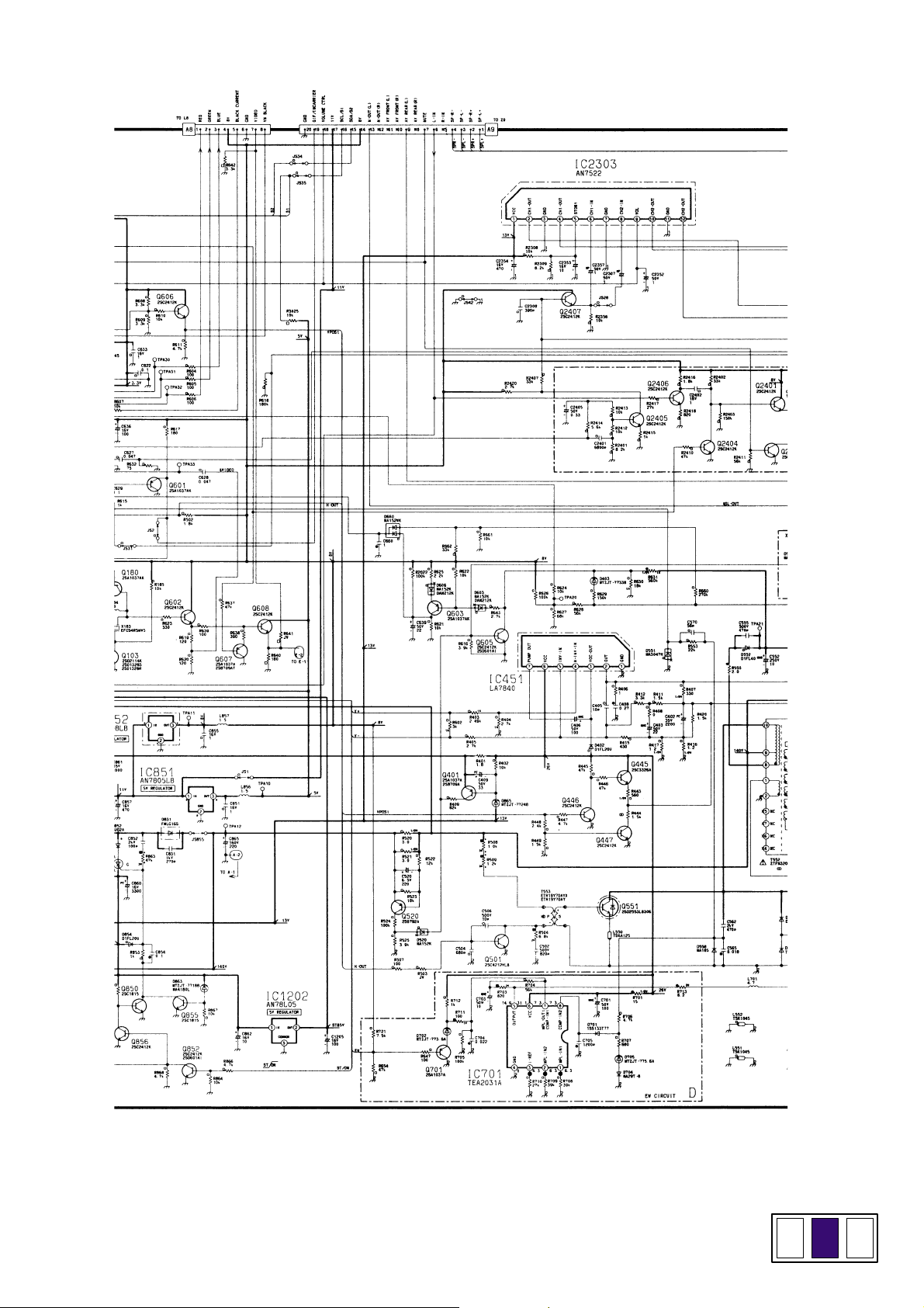
Panasonic TX-21PM30T Schematic
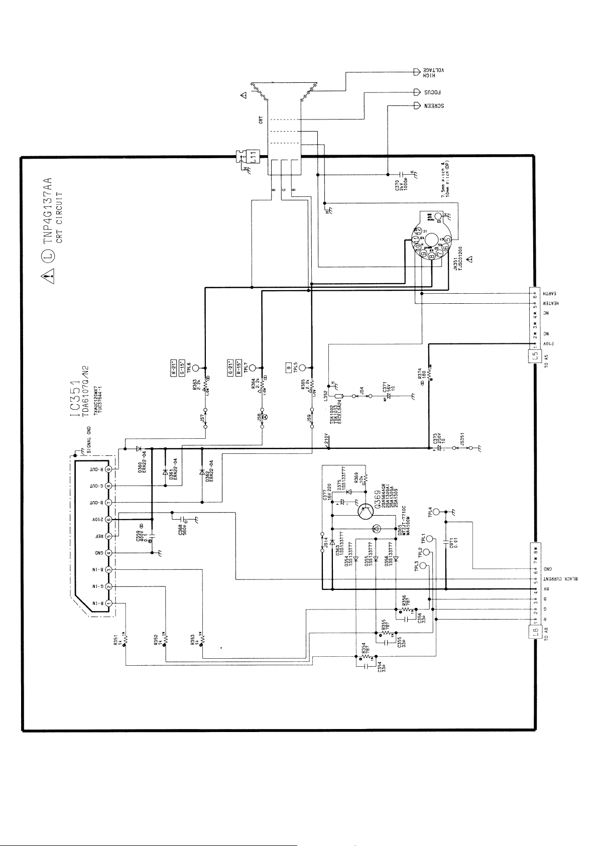
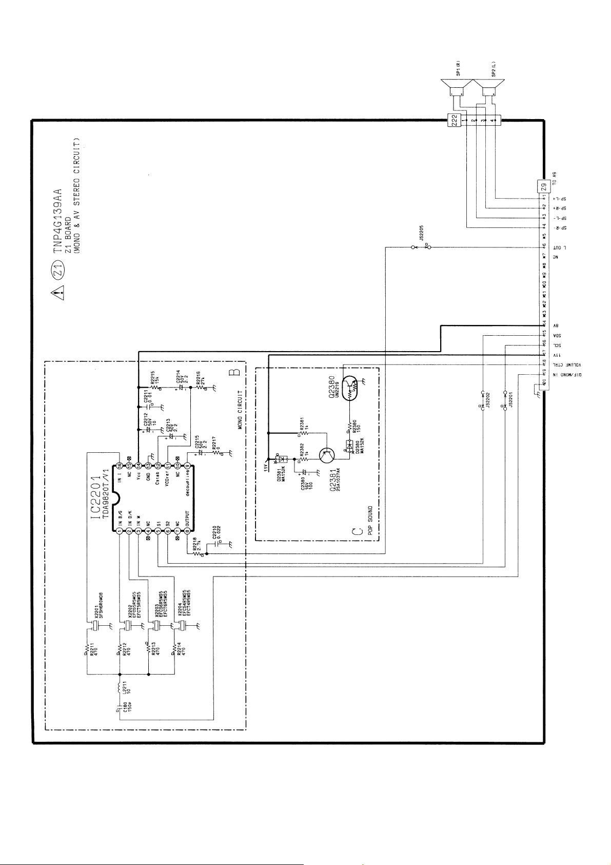
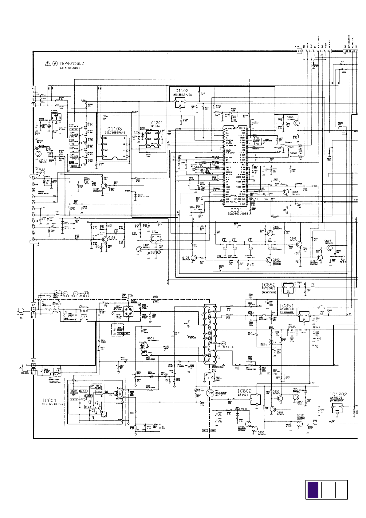
6 Schematic Diagram for models TX-21PM30T (MX-7
Chassis)
IMPORTANT SAFETY NOTICE Components identified by
! mark have special characteristics important for safety.
When replacing any of these components, use only
manufacturer’s specified parts.
Notes:
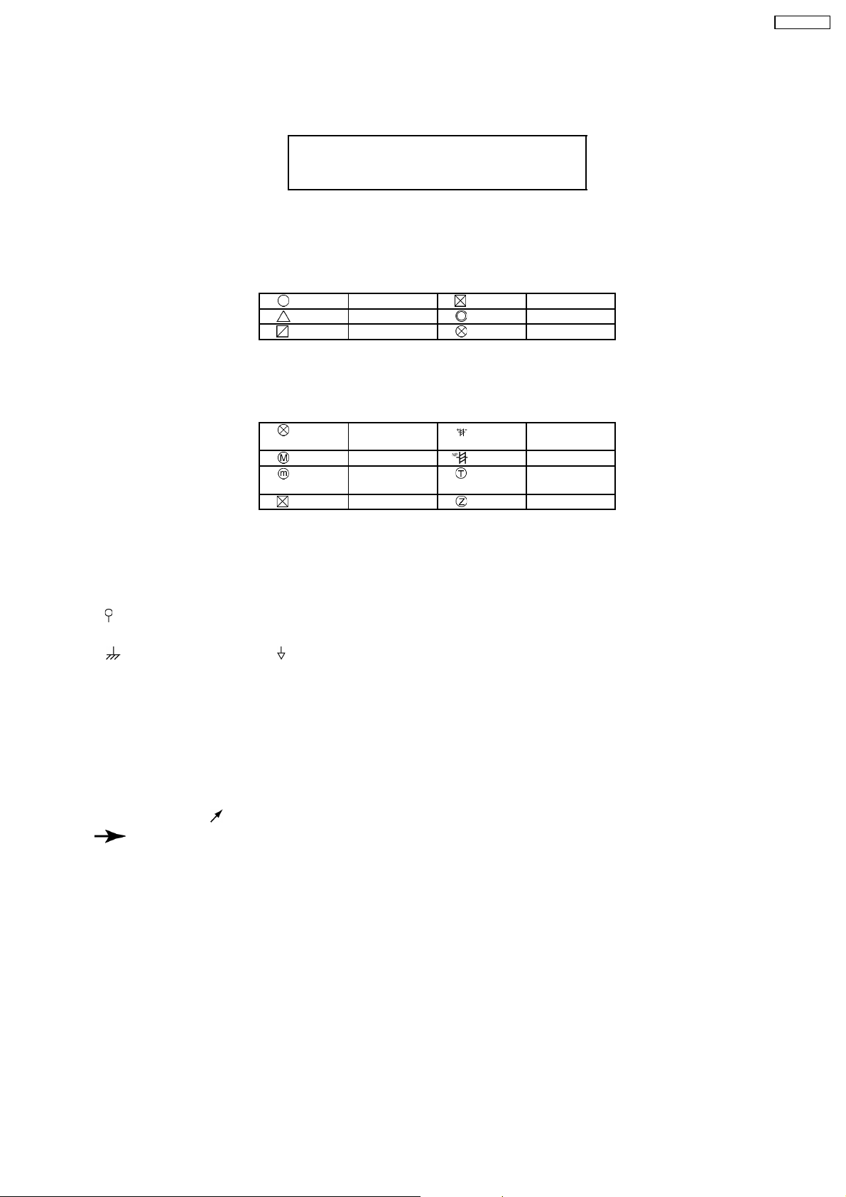
1. Resistor
All resistors are carbon 1.4W resistors unless marked as follows:
Unit of resistance is OHM (Ω) (K=1 000 M=1 000 000)
Nonflammable Metal Oxide
Solid Metal Film
Wire Wound Fuse
2. Capacitor
All capacitors are ceramic 50V capacitors unless marked as follows:
Unit of capacitance is µF, unless otherwise noted.
Temperature
Compensation
Polyester Bipolar
Metalized
Polyester
Polypropylene Z-Type
Electrolytic
Dipped
Tantalum
TX-21PM30T
3. Coil
Unit of inductance is µH, unless otherwise noted.
Unit of resistance is OHM (Ω) (K=1 000 M=1 000 000)
4. Test Point
: Test Point position
5. Earth Symbol
: Chassis Earth (Cold) : Line Earth (Hot)
6. Voltage Measurement
Voltage is measured using a DC voltmeter.
Conditions of the measurement are the following:
Power Source..........................AC 220V, 50Hz
Receiving Signal.....................Colour Bar signal (RF)
All customer’s controls............Maximum positions
7. Number in red circle indicates waveform number.
(See waveform pattern table)
8. When arrow mark (
9.
: Indicates the major signal flow.
) is found, connection is easily found from the direction of arrow.
10. This schematic diagram is the latest at the time of printing and subject to change without notice.
Remarks:
1. The Power Circuit contains a circuit area which uses a separate power supply to isolate the earth connection. The circuit is
defined by HOT and COLD indications in the schematic diagram. Take the following precautions:
All circuits except the Power Circuit are cold.
Precautions:
a Do not touch the hot part or the hot and cold parts at the same time or you may be
shocked
b Do not short-circuit the hot and cold circuits or a fuse may blow and parts may break
c Do not connect an instrument such as an oscilloscope to the hot and cold circuits
simultaneously or a fuse may blow. Connect the earth of instruments to the earth
connection of the circuit being measured.
d Make sure to disconnect the power plug before removing the chassis.
2. The following diodes are interchangeable: MA150 - MA162 (Replacement part).
13
 Loading...