

Page 1
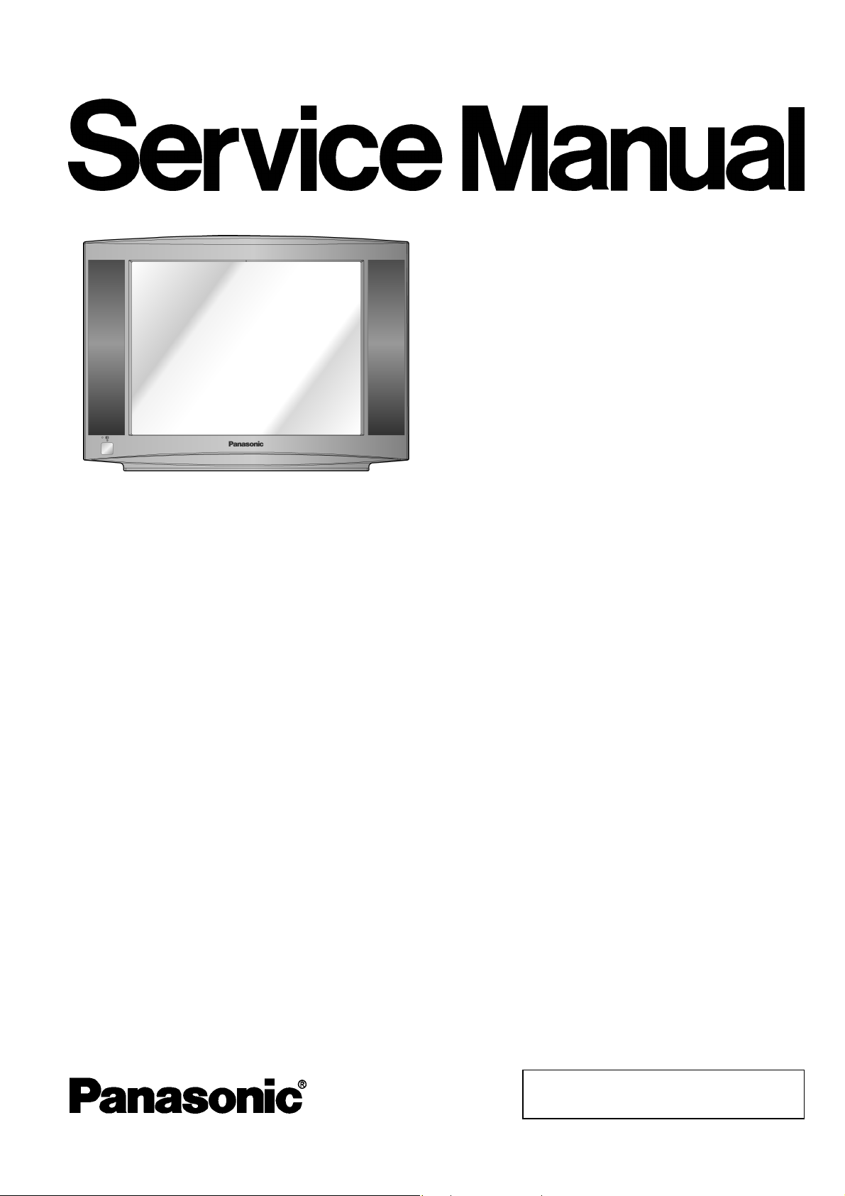
Colour Television
TX-21RX20T
GP41Z Chassis
ORDER NO. MTV0801643CE
Specifications
Power Source : AC SINGLE 220-240 V, 50/60 Hz
Power Consumption : 86 W
Aerial Impedance : 75 Ω unbalanced
Coaxial type
Receiving System : 17 Systems
SYSTEMS FUNCTIONS
———————————————————————————————
1 PAL B, G, H
2 PAL I Reception
3 PAL D, K
4 SECAM B, G
5 SECAM D, K
6 SECAM K1
7 NTSC M
(NTSC 3.58 / 4.5 MHz)
———————————————————————————————
8 NTSC 4.43 / 5.5 MHz
9 NTSC 4.43 / 6.0 MHz
10 NTSC 4.43 / 6.5 MHz
11 NTSC 3.58 / 5.5 MHz Playback from
12 NTSC 3.58 / 6.0 MHz
13 NTSC 3.58 / 6.5 MHz
14 SECAM I
———————————————————————————————
15 PAL 60 Hz / 5.5 MHz Playback from
16 PAL 60 Hz / 6.0 MHz
17 PAL 60 Hz / 6.5 MHz
of broadcast
transmission and
playback from
video cassette tape
recorders.
special VCR only.
special Disc player
and VCR only.
Receiving Channels :
VHF 2-12 PAL / SECAM B, K1
0-12 PAL B (AUST)
1-9 PAL B (N. ZEALAND)
1-12 PAL / SECAM D
1-12 NTSC M (JAPAN)
2-13 NTSC M (U.S.A.)
UHF 21-69PALG,H,I/SECAMG,K,K1
28-69 PAL B (AUST)
13-57 PAL D, K
13-62 NTSC M (JAPAN)
14-69 NTSC M (U.S.A.)
CATV S1-S20 (OSCAR)
1-125 (U.S.A. CATV)
C13-C49 (JAPAN)
S21-S41 (HYPER)
Z1-Z37 (CHINA)
5A, 9A (AUST)
Tuning System : Frequency synthesizer
Auto search tuning : 100 position
© 2008 Matsushita Electric Industrial Co., Ltd. All
rights reserved. Unauthorized copying and
distribution is a violation of law.
Page 2
A
TX-21RX20T
Video / Audio Terminal :
DVD
Y 1.0 Vp-p 75 Ω
P
B
P
R
V1,2,3
Video In 1Vp-p75Ω
Audio In Approx. 0.5 V, 47 kΩ
Monitor Out
Video Out 1Vp-p75Ω
Audio Out Approx. 0.5 V, 1 kΩ
Picture Tube : Viewable Picture tube measured
0.7 Vp-p 75 Ω
0.7 Vp-p 75 Ω
diagonally : 51 cm
Measured diagonally,
Audio Output : 10 W x 2 = 20 W
Operating Conditions :
Temperature : 0°C - 35°C
Humidity : 20°C - 80°C RH (non-condensing)
Dimensions : Height : 431 mm
Mass : 20.5 kg (Net)
Specifications are subject to change without notice.
Mass and dimensions shown are approximate.
90° deflection
Width : 596 mm
Depth : 340 mm
CONTENTS
Page Page
1 Safety Precautions
1.1. General Guidelines
1.2. Leakage Current Cold Check
1.3. Leakage Current Hot Check (Fig. 1)
1.4. X-Radiation
1.5. SW-Board Fix to Cabinet
1.6. GP41Z Chassis Block Diagram
2 Service Hints
2.1. Service Position for E-Board
2.2. Service Mode Explanation
2.3. Adjustment for White Balance
2.4. Adjustment for CRT CUT OFF
2.5. Adjustment Procedure
2.6. Adjustment of Purity
3 Location of Lead Wiring
3.1. Wire Dressing
3
3
3
3
4
4
5
6
6
6
7
7
7
8
20
20
3.2. Wire Dressing and Connections
4 Conductor Views
5 Schematic Diagram
5.1. A Board
5.2. L Board
5.3. V Board
5.4. G Board
5.5. P Board
5.6. K Board
5.7. SW Board
6 Parts Locations
6.1. Packing Exploded View - A
6.2. Packing Exploded View - B
6.3. Parts Locations
7 Replacement Parts List
7.1. Replacement Parts List
21
22
23
25
30
33
35
37
38
39
41
41
42
43
44
45
2
Page 3
TX-21RX20T
1 Safety Precautions
1.1. General Guidelines
1. It is advisable to insert an isolation transformer in the AC supply before servicing this hot chassis.
2. When servicing, observe the original lead dress, especially the lead dress in the high voltage circuits. If a short circuit is found,
replace all parts which have been overheated or damaged by the short circuit.
3. After servicing, see to it that all the protective devices such as insulation barriers, insulation papers, shields and isolation R-C
combinations are properly installed.
4. When the receiver is not to be used for a long period of time, unplug the power cord from the AC power socket.
5. Potential, as high as 25.0 kV is present when this receiver is in operation. Operation of the receiver without the rear cover
involves the danger of a shock hazard from the receiver power supply. Servicing should not be attempted by anyone who is not
thoroughly familiar with the precautions necessary when working on high voltage equipment. Always discharge the anode of the
picture tube to the receiver chassis before handling the tube. After servicing, make the following leakage current check to
prevent the customer from being exposed to shock hazards.
1.2. Leakage Current Cold Check
1. Unplug the power cord and connect a jumper between the two prongs on the plug.
2. Turn on the receiver’s power switch.
Measure the resistance value, with an ohmmeter, between the jumper and each exposed metallic cabinet part on the receiver,
such as screw heads, aerials, connectors, control shafts, etc. When the exposed metallic part has a return path to the chassis,
the reading should be between 4 MΩ and 20 MΩ. When the exposed metal does not have a return path to the chassis, the
reading must be infinite.
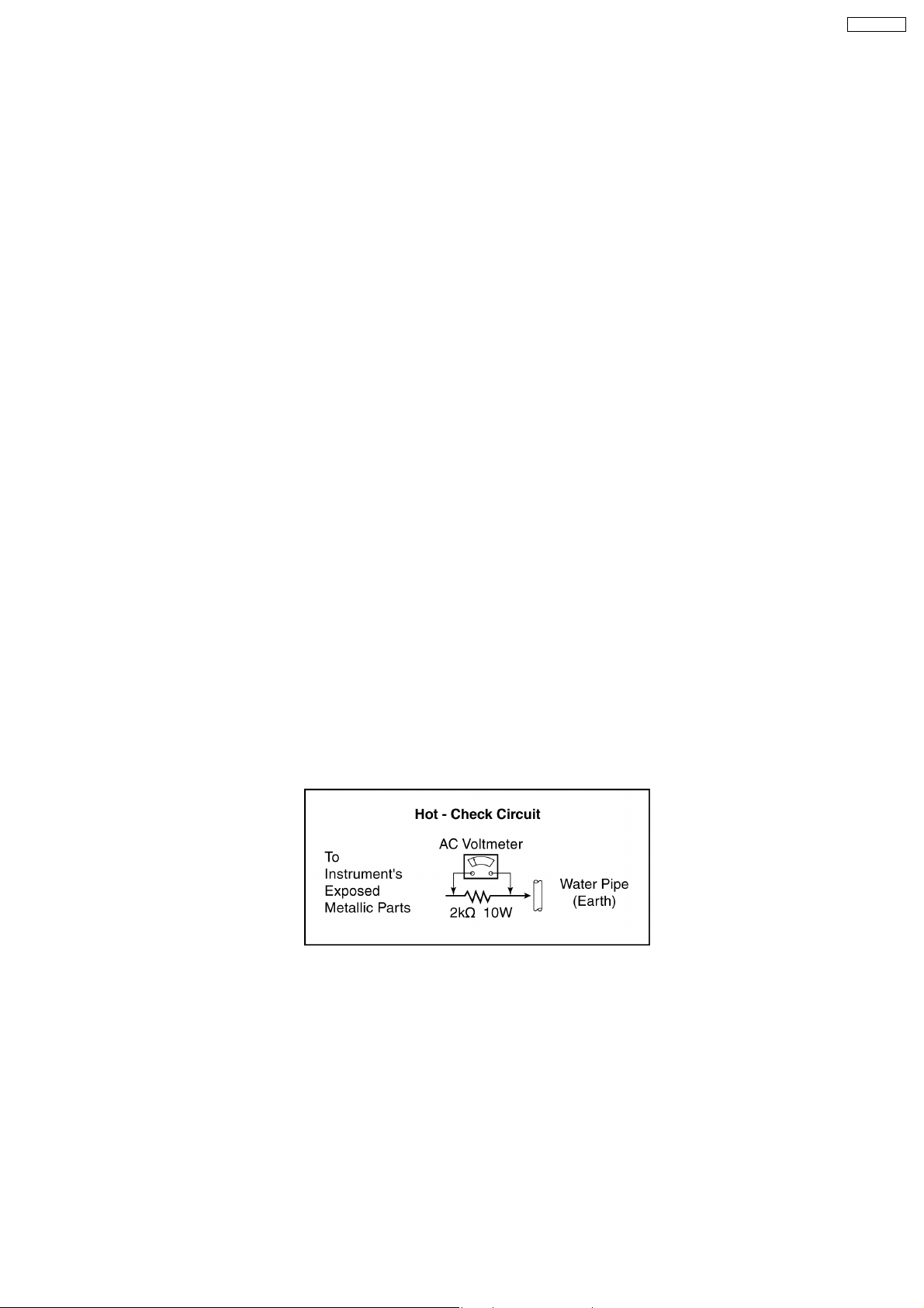
1.3. Leakage Current Hot Check (Fig. 1)
1. Plug the power cord directly into the power socket. Do not use an isolation transformer for this check.
2. Check that a 2 kΩ non-inductive resistor and an AC/DC current meter are in series with each exposed metallic part on the
receiver in turn and an earth such as a water pipe.
The current from any point should not exceed 0.7 mA peak AC or 2 mA DC. In the case of a measurement being outside of
these limits specified, there is a possibility of a shock hazard and the receiver should be repaired and rechecked before it is
returned to the customer.
Fig. 1
3
Page 4
TX-21RX20T
1.4. X-Radiation
Warning:
The potential sources of X-Radiation in TV set are the EHT section and the picture tube. When using a picture tube test jig for
service, ensure that the jig is capable of handling 25.5 kV without causing X-Radiation.
Note: It is important to use an accurate periodically calibrated high voltage meter.
1. Set the brightness to minimum.
2. Use the remote to get into Service Mode.
3. Measure the EHT. The meter reading should indicate 24.0 ± 1.5 kV. If the meter indication is out of tolerance, immediate
service and correction are required to prevent the possibility of premature component failure.
4. To prevent the possibility of X-Radiation, it is essential to use the specified picture tube, if service replacement becomes
necessary.
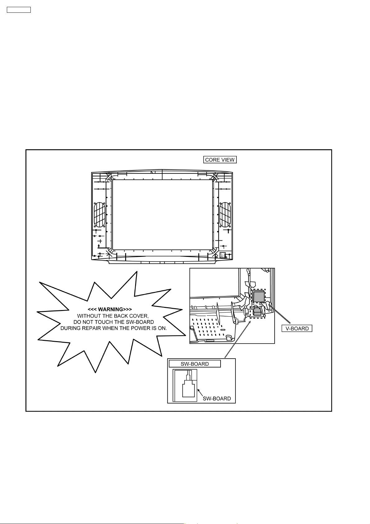
1.5. SW-Board Fix to Cabinet
4
Page 5
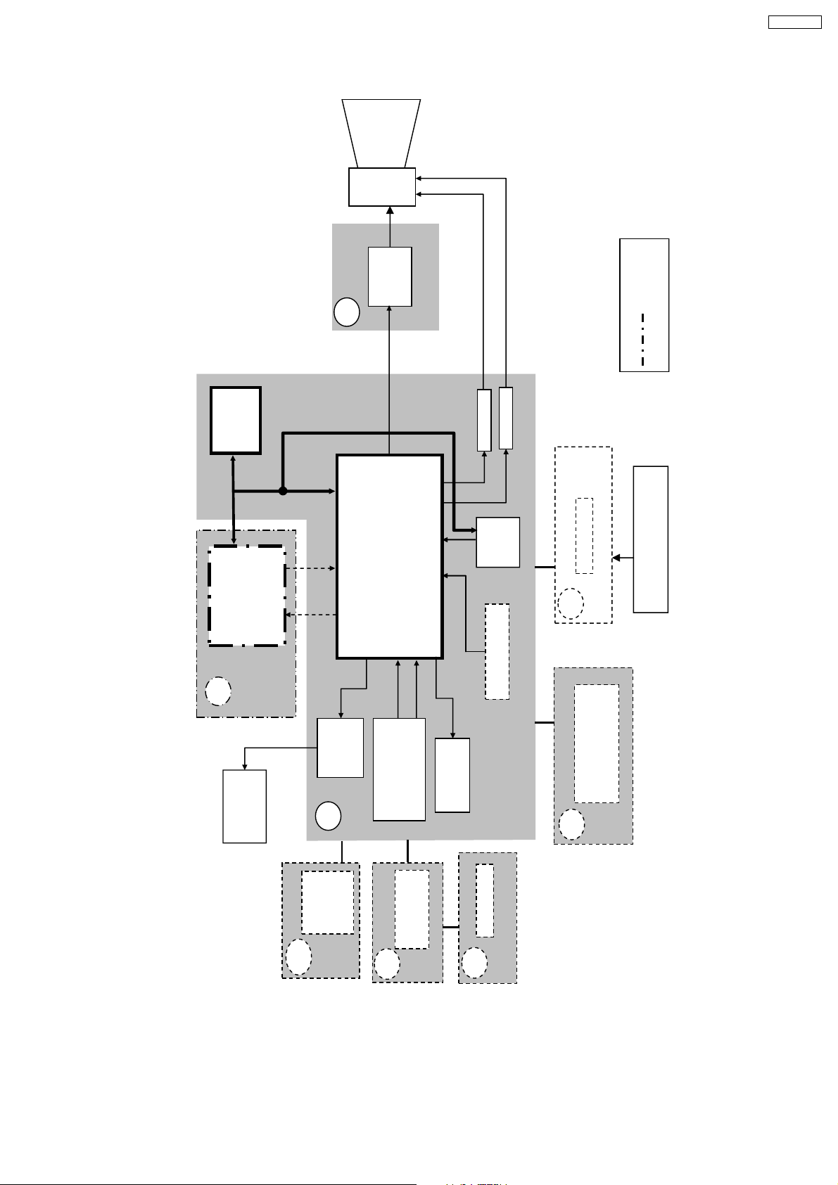
1.6. GP41Z Chassis Block Diagram
CRT
coil
defl.
CRT
DRIVE
L
TX-21RX20T
PIP MODEL
IC1101
EEPROM
SCL
SDA
PVP
PP
SPEAKER
R/G/B
IC1801
CVBS IN
SCL SDA
R/G/B
CVBS OUT
AMP
IC2301
AUDIO
A
R
G
IC601
VCT-IF
OUT
AUDIO
V_IN
REAR INPUTS
AV1 : V/L/R
B
V
H
IF
GEO
A_IN
MON_OUT
V/L/R
MON_OUT
AV3 : YUV/V/L/R
V OUT
H OUT
TUNER
GEOMAGNETIC
LINE FILTER
P
&
REMOTE RECEIVER
ONLY FOR MODEL WITH
5TH HARMONIC COIL
LED
V
SW
MAIN
POWER
SWITCH
AV2 : V/L/R
SIDE INPUTS
G
5
PANEL KEY
K
Page 6
TX-21RX20T
2 Service Hints
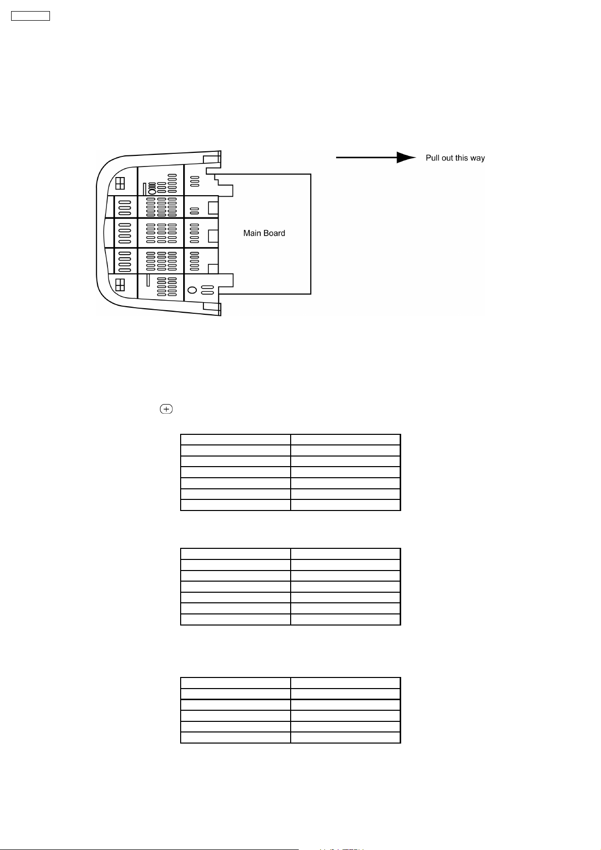
2.1. Service Position for E-Board
1. Remove the back cover.
2. Stand the TV set as shown in Fig. 2.
3. Remove the A-Board from the TV set by pulling the main board out as shown in Fig. 2.
Fig. 2
2.2. Service Mode Explanation
1. Service Mode Access
a) Set the timer ON.
b) Press remote’s RECALL (
2. Service Mode 1 Controls
3. Service Mode 2 Controls
To enter SERVICE 2; press channel key ‘1’ in SERVICE 1 entry screen.
) and panel’s volume down key simultaneously to enter SERVICE 1.
Key 3/4 Previous/Next Service 1 Item
Key 8/9 Adjust user Brightness (-/+)
Program up/down Program position up/down
Volume + Increment of selected item
Volume - Decrement of selected item
OK Store/Save selected item
Normalize Exit service mode
Key 3/4 Previous/Next Service 2 Item
Key 8/9 Toggle for option bit 0-7
Program up/down Program position up/down
Volume + Increment of selected item
Volume - Decrement of selected item
OK Store/Save selected item
Normalize Exit service mode
NOTE:- Service Mode 2 options bit refer to each model front cover spec.
4. Service Mode 3 Controls
To enter SERVICE 3; press channel key ‘1’ in SERVICE 2 entry screen.
Key 3/4 Previous/Next Service 1 Item
Program up/down Program position up/down
Volume + Increment of selected item
Volume - Decrement of selected item
OK Store/Save selected item
Normalize Exit service mode
6
Page 7
2.3. Adjustment for White Balance
Preparation:
1. Receive the white balance pattern and aging should be performed over 30 minutes.
2. Set the picture menu to DYNAMIC NORMAL.
3. Degausse the CRT face.
4. Fix the CRT colour analyzer receiver unit to CRT face.
Adjustment of Low Light
1. Adjustment Sub Bright, so that Y = 6.5 ± 1.0 nit.
2. Adjustment R-CUT OFF, so that X = 0.241 ± 0.005 nit.
3. Adjustment G-CUT OFF, so that Y = 0.242 ± 0.005 nit.
Adjustment of High Light
1. Adjustment Sub Bright, so that Y = 150 nit.
2. Adjustment R-Drive, so that X = 0.263 ± 0.003 nit.
3. Adjustment B-Drive, so that Y = 0.261 ± 0.003 nit.
TX-21RX20T
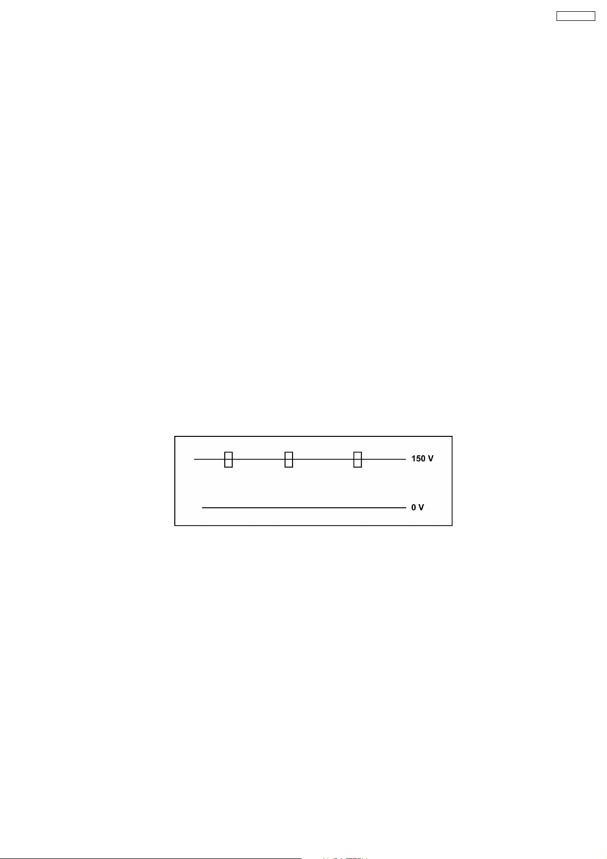
2.4. Adjustment for CRT CUT OFF
Preparation:
1. Connect the oscilloscope probe to TPL5.
2. Screen VR min.
3. Set the data Sub Bright, Bright.
4. In service Mode at “Bright” dac press [5] in factory mode to enter vertical line and adjust by volume down or up button.
5. Adjust “Screen VR” until 1-H Line appears.
2.5. Adjustment Procedure
2.5.1. +B Voltage
Item / preparation
1. Operate the TV set.
2. Set control as follows :
Brightness ........... minimum
Contrast ............... minimum
Adjustment procedure
1. Confirm the DC voltage at the indicated test points, as follows :
TPA 15 : 3.35 ± 0.2 V
TPA 16 : 130 ± 2 V
TPA 17 : 8.25 ± 0.35 V
TPA 18 : 1.85 ± 0.15 V
TPA 19 : 5.30 ± 0.2 V
TPA 20 : 188 ± 15 V
7
Page 8
TX-21RX20T
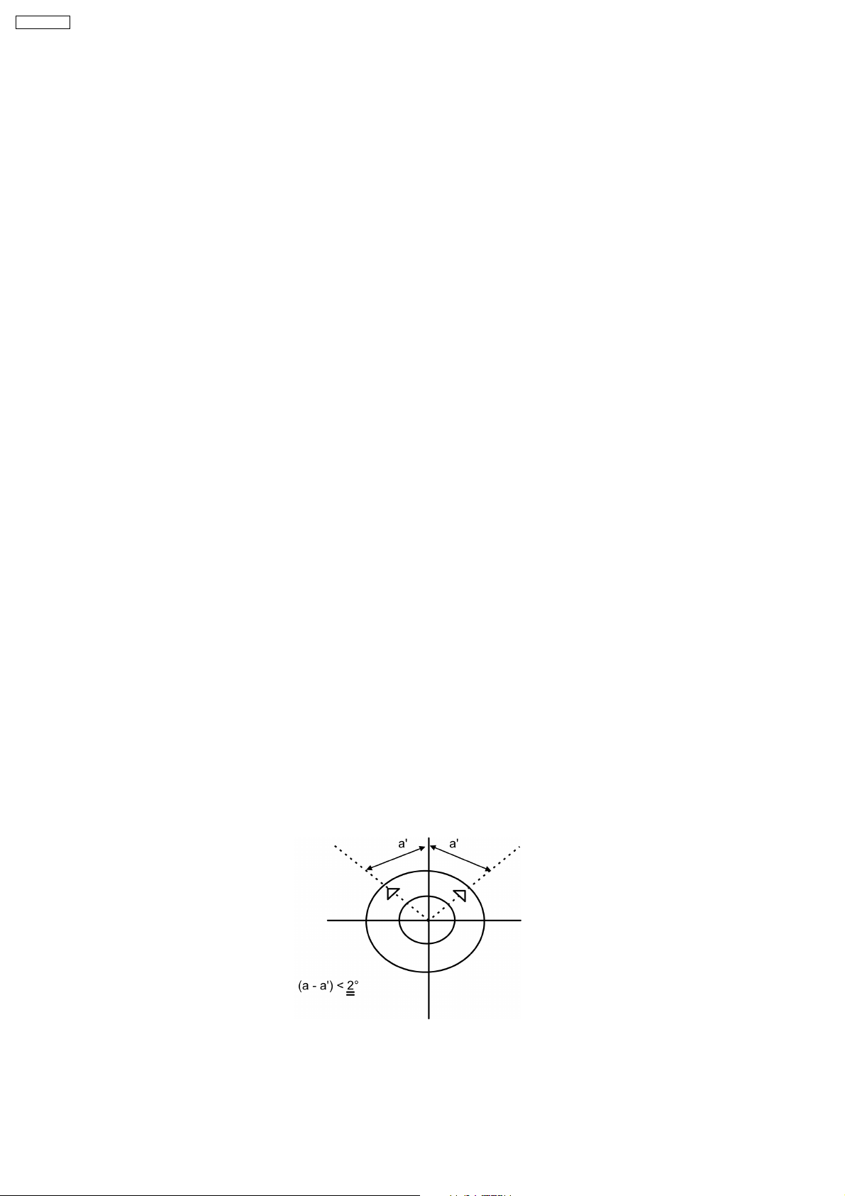
2.5.2. High Voltage
Item / preparation
1. Receive the crosshatch pattern.
2. Set to 0 Beam.
Screen VR .......... minimum
Contrast .............. minimum
Adjustment procedure
1. Connect a DC voltage meter to TPA 16 and confirm the +B voltage is 130.0 V ± 2.
2. Connect a high frequency voltmeter to heater and confirm that voltage reads 6.3 V (RMS) ± 0.24.
3. Normalize the brightness and contrast.
2.6. Adjustment of Purity
1. INSTRUMENTS
a. Purity Jig
b. Helmhortz device
2. PREPARATION
a. Set the Helmhortz device to local magnetic field.
Horizontal : 0 ± 0.03 × 10⁻⁴T
b. Aging should be performed over 60 minutes.
c. Receive the purity pattern (White pattern).
d. Picture menu : CONTRAST ... Max. BRIGHT ... Max.
e. Set V-CENTER to [4].
f. Static convergence should have been roughly adjusted.
g. Connect DC current meter through FBT (pin 3) and adjust to [1200 ± 10%] µA.
3. ADJUSTMENT
a. Set both purity magnets’ knobs to top.
b. Adjust the purity so that the markers on monitor scope of purity jig become symmetrical in horizontal direction.
c. Only for stripe CRT, correct vertical centre by purity magnet too.
d. Set up deflection yoke so that the position of deflection yoke becomes [10 µm ± 5] forward on monitor scope at this time by
attention note to tile deflection yoke.
e. Repeat procedures (a) ~ (d).
f. Tighten deflection yoke band.
g. Adjust beam landing by microscope. (Only for model change or check instruments)
8
Page 9
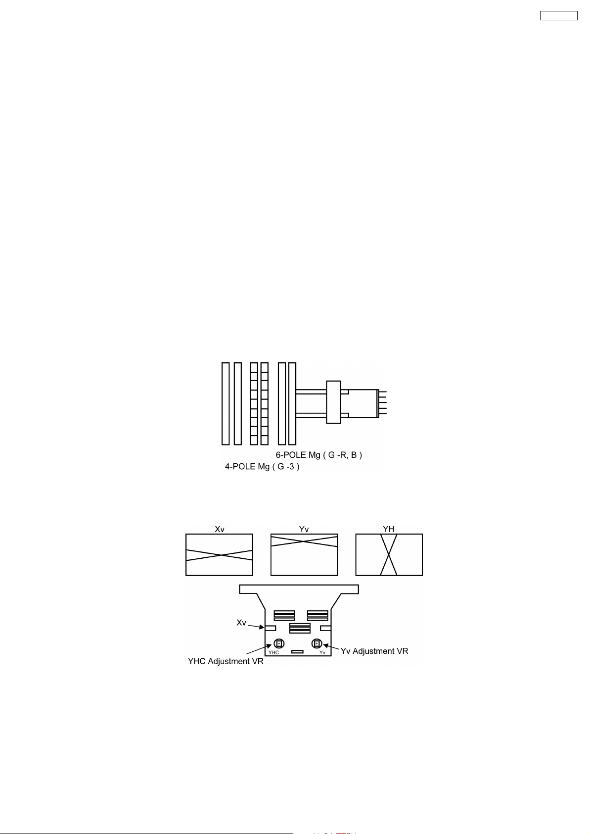
ADJUSTMENT OF CONVERGENCE
1. INSTRUMENT
a. Helmhortz device
2. PREPARATION
a. Set the Helmhortz device to local magnetic field.
Horizontal : 0 ± 0.03 × 10⁻⁴T
b. Receive the crosshatch pattern.
c. Picture menu : DYNAMIC Normal and adjust BRIGHT DAC until gray portion of crosshatch.
d. Set DY to CRT not to tilt (up and down and left right).
3. ADJUSTMENT
a. Static Convergence Adjustment
a. Make sure that the magnets are positioned as shown as in Fig. 1.
b. Adjust the 4-pole magnets (Fig. 1) to align centre dots of R and B adjust 6-pole magnets to align centre dots to G.
c. After adjustment, secure magnets with magnet lock of white lacquer.
• Beams move with rotating when static magnet is turned. Rotational reduce of beams differs by angle of two
magnets. Therefore, repeat magnet adjustment several times so that all are aligned completely.
b. YHC, YV, XV Adjustment (Fig. 2)
a. Adjust that static and Dynamic convergence is best with YHC VR, YV VR and XV coil. In case static convergence is
tilted, repeat (1) Static Convergence Adjustment.
c. Dynamic Convergence Adjustment
a. When dynamic convergence is bad, fix permalloy between neck and DY so that dynamic convergence best.
TX-21RX20T
Fig. 1
4. CONFIRM THAT LEFT UPPER SIDE LINE IS STRAIGHT.
When left upper side line is not straight, put magnet on DY and adjust the left upper side line so it is straight.
Fig. 2
9
Page 10
TX-21RX20T
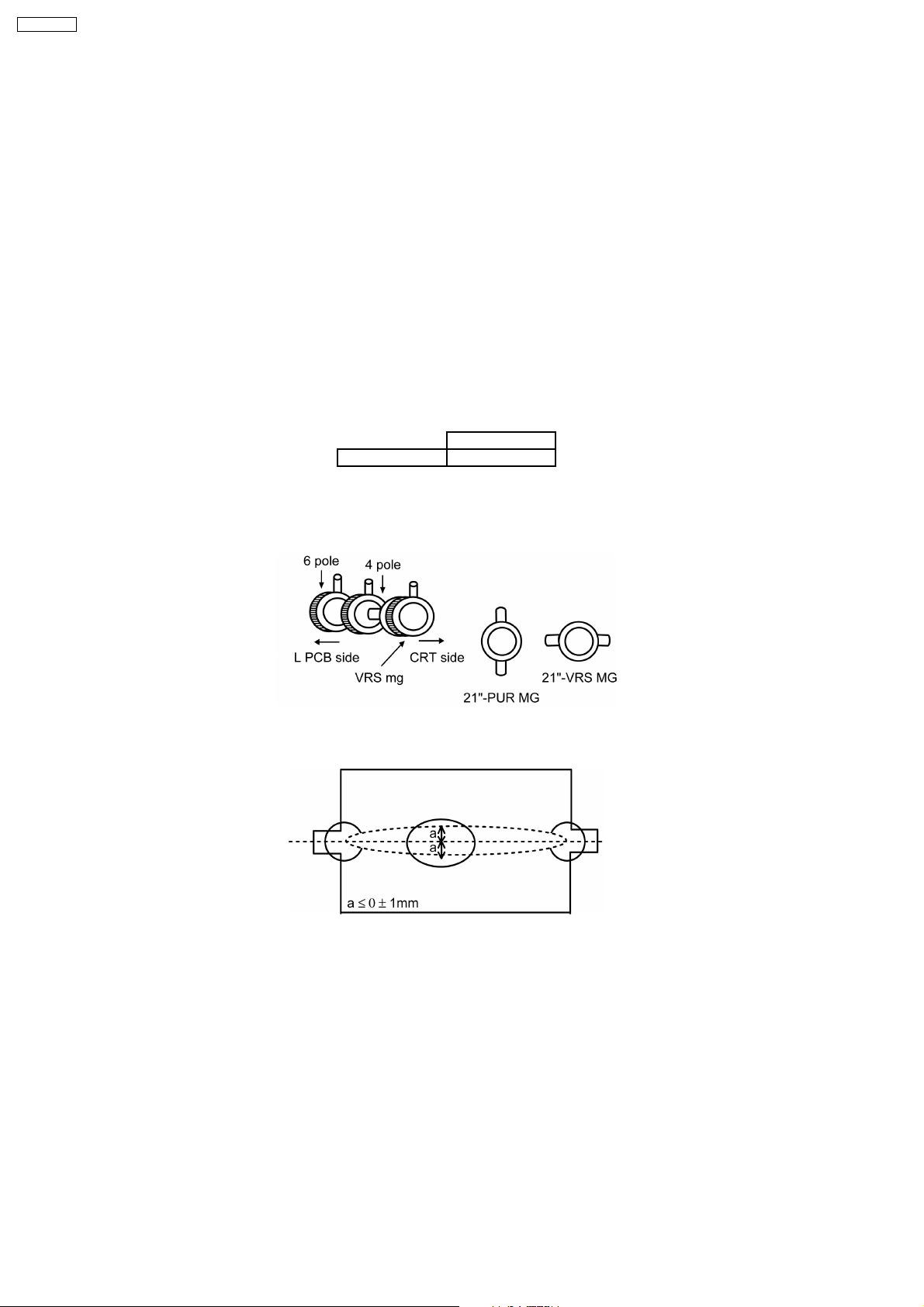
ADJUSTMENT OF CRT VRS
1. PREPARATION
a. Set DY to CRT not to tilt up and down left and right deflection. (Fig. 1)
b. Set CY to CRT and set CY magnet primarily.
Pur Mg : Set Pur Mg so that 2 magnets are horizontal position.
VRS Mag : Set VRS Mg so that 2 magnets are top position.
c. Set geomagnetic correction DAC. As in TABLE 1.
2. ADJUSTMENT
a. Receive the white balance pattern.
b. Adjust V-CENTER.
c. Set R,B CUT OFF to minimum, and set G CUT OFF to centre.
d. Receive the aging pattern.
e. Set 2 magnets of vertical position to up and down equally so that centre part of CRT. (Fig. 2)
MANUAL
DAC 0
TABLE 1
Fig. 1
Fig. 2
10
Page 11
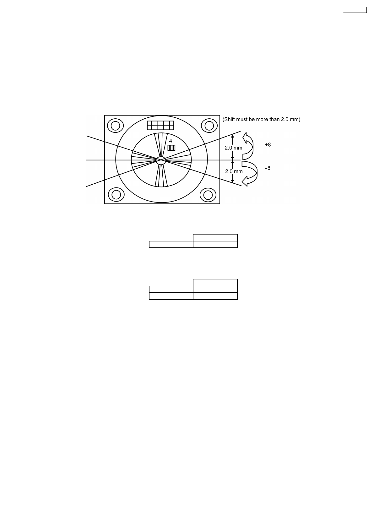
TERRESTRIAL MAGNETISM CIRCUIT CONFIRMATION
1. CONFIRMATION OF GEOMAGNETIC CIRCUIT
a. Select GEOMAGNETIC mode in PRESET MENU.
b. Confirm that it leans right side as shown (Fig. 1), when change the DAC (*).
c. Confirm that it leans left side as shown (Fig. 1), when change the DAC (**).
d. Confirm that purity is changed, when changing the DAC.
e. Set Geomagnetic DAC as in TABLE 1.
TX-21RX20T
Fig. 1
MANUAL
DAC 0
TABLE 1
MANUAL
*DAC -1 ~ -8
**DAC +1 ~ +8
TABLE 2
11
Page 12
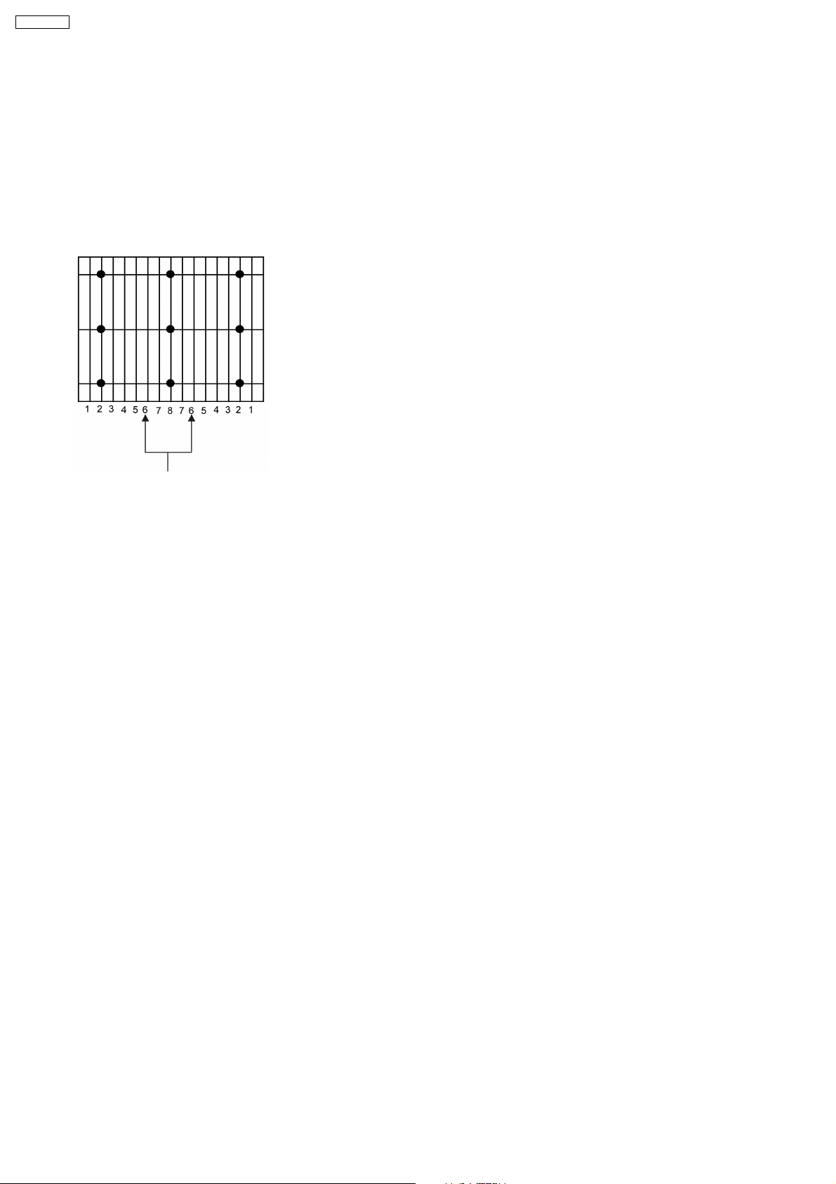
TX-21RX20T
FOCUS ADJUSTMENT
1. PREPARATION
a. Receive crosshatch pattern E-4
b. Picture menu : DYNAMIC NORMAL
2. ADJUSTMENT
a. Adjust focus VR for best position.
Adjust focus base on no. 6 line
Fig. 1. Crosshatch Pattern
12
Page 13
DEFLECTION
Note:- For Philippines model, all 50 Hz adjustment is made in AV mode.
A . DEFLECTION ADJUSTMENT / CONFIRMATION (50 Hz, 4:3 Mode ONLY)
(Service 1)
1. INSTRUMENT
a. Helmhortz device
2. PREPARATION
a. Set the Helmhortz device to local magnetic field.
b. Picture menu : DYNAMIC Normal
3. CONFIRMATION AND ADJUSTMENT
a. Adjustment of 50 Hz V-CENTER
a. Receive the monoscope pattern (E11).
b. Adjust V-POS so that centre of monoscope pattern is at CRT centre.
TX-21RX20T
b. Adjustment of 50 Hz V-AMP
a. Receive the monoscope pattern (E11).
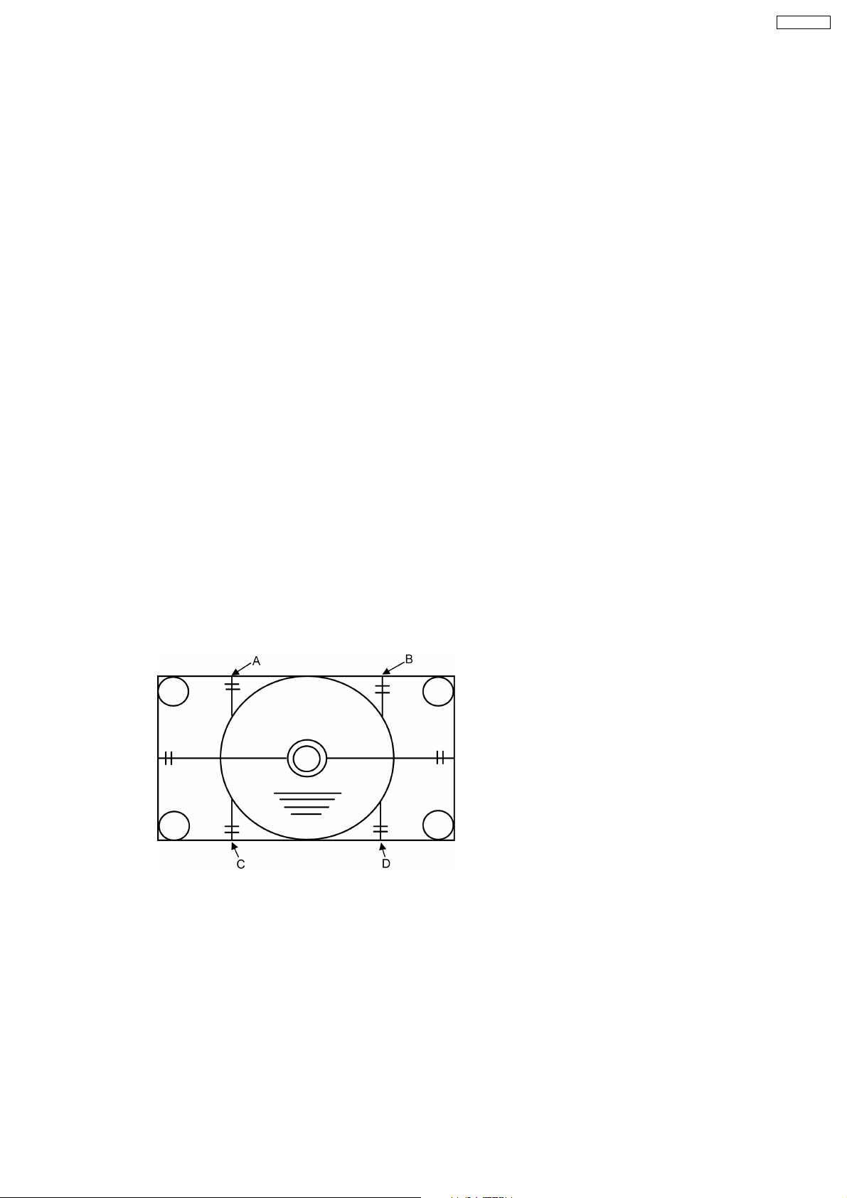
b. Adjust V-AMP so that
C, D (Fig. 3) is 2.0 ± 0.1
A, B (Fig. 3) is 2.0 ± 0.1
c. Adjustment of 50 Hz H-CENTER
a. Receive the monoscope pattern (E11).
b. Adjust H-POS so that horizontal position is at centre of CRT.
Fig. 3
13
Page 14
TX-21RX20T
B . DEFLECTION ADJUSTMENT / CONFIRMATION (50 Hz, 4:3 Mode ONLY)
(Service 1)
1. INSTRUMENT
a. Helmhortz device
2. PREPARATION
a. Set the Helmhortz device to local magnetic field.
b. Picture menu : DYNAMIC Normal
3. CONFIRMATION AND ADJUSTMENT
a. Adjustment of 50 Hz V-CENTER
a. Receive the Philips pattern (US11).
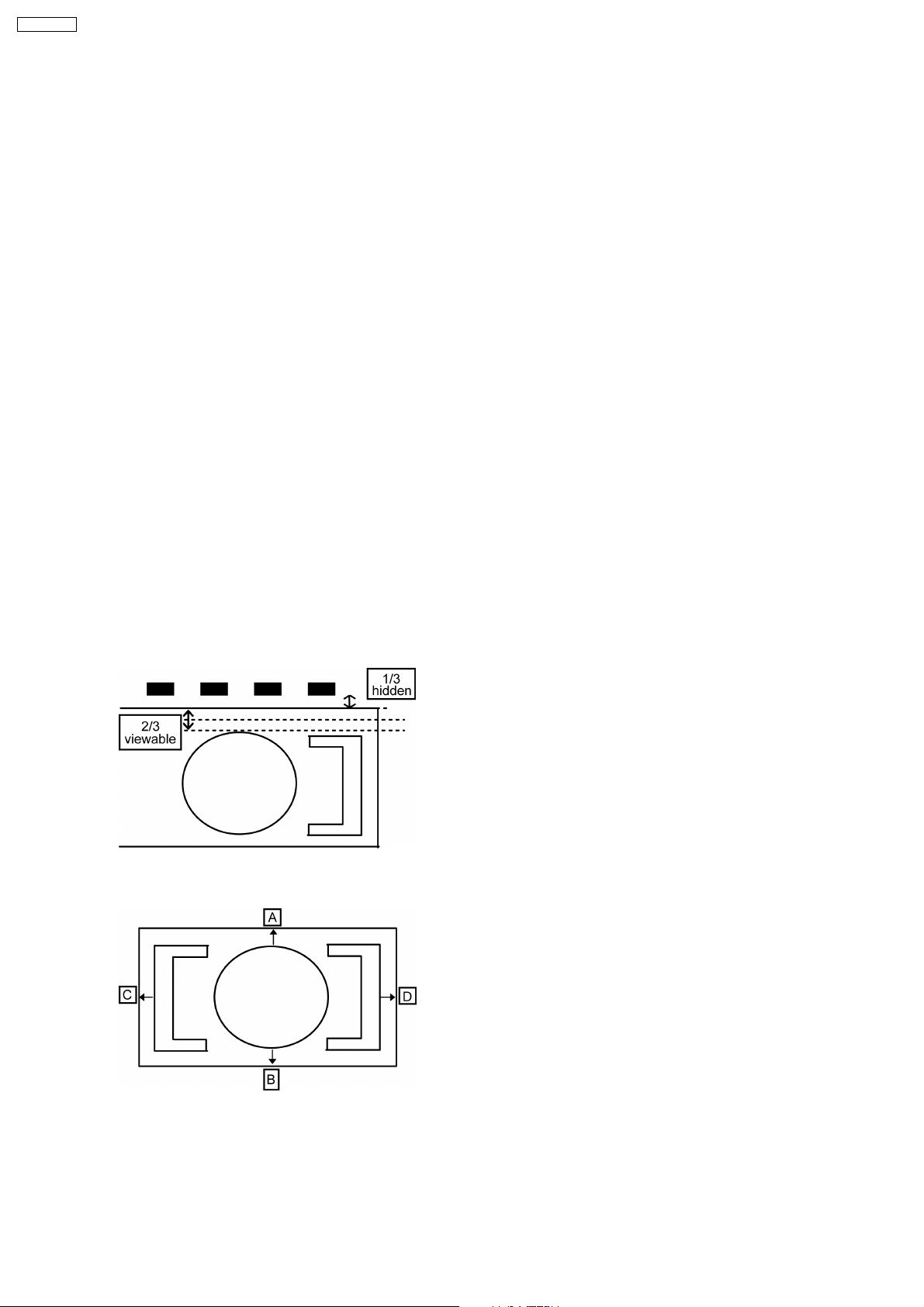
b. Adjust V-POS so that centre of Philips pattern is at 2/3 of Top and Bottom.
A, B (Fig. 3c) is 2/3 of viewable size
b. Adjustment of 50 Hz V-AMP
a. Receive the Philips pattern (US11).
b. Adjust V-AMP so that
A (Fig. 3b) is 2/3 of viewable size
c. Adjustment of 50 Hz H-CENTER
a. Receive the Philips pattern (US11).
b. Adjust H-POS so that horizontal position is at centre of CRT.
C, D (Fig. 3c) is 2/3 of viewable size
Fig. 3b
Fig. 3c
14
Page 15
4. ADJUSTMENT OF 50 Hz H-AMP
a. Receive the monoscope pattern (E11).
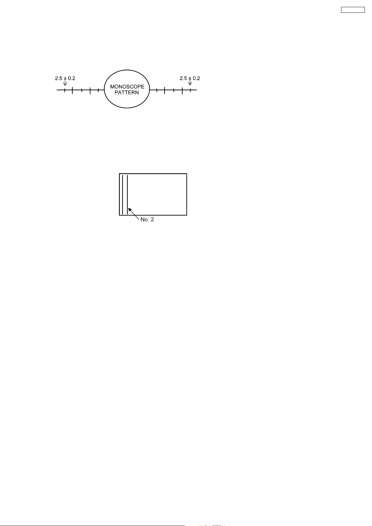
b. Adjust H-AMP so that both edges are within 2.5 ± 0.2. Refer to Fig. 1.
Fig. 1
5. EW ADJUSTMENT / CONFIRMATION
a. PREPARATION
a. Receive crosshatch pattern (E4).
b. EW ADJUSTMENT
a. Adjust the vertical line no. 2 to straight line (parabola) by EW-AMP 1. (Refer to Fig. 1c)
TX-21RX20T
Fig. 1c
15
Page 16
TX-21RX20T
(16:9 MODE) ADJUSTMENT / CONFIRMATION
1. V-ZOOM (16:9) ADJUSTMENT
(Service 3)
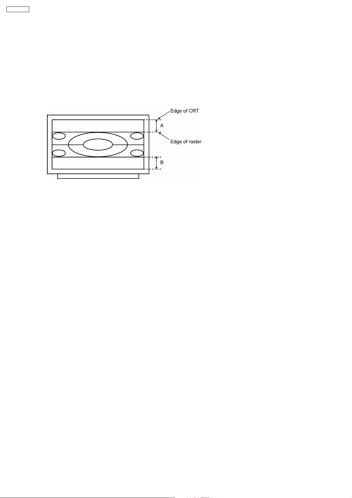
*a. Receive PAL monoscope pattern E11. (If no burst signal : Set to force PAL)
b. Set the aspect to 16:9.
c. Confirm that A, B in Fig. 1 is 4.0 cm ± 1.5, if not, adjust V-ZOOM.
d. Receive NTSC monoscope patern US13. (If no burst signal : Set to force NTSC)
c. Confirm that A, B in Fig. 1 is *a, if not, adjust V- ZOOM.
Fig. 1
16
Page 17
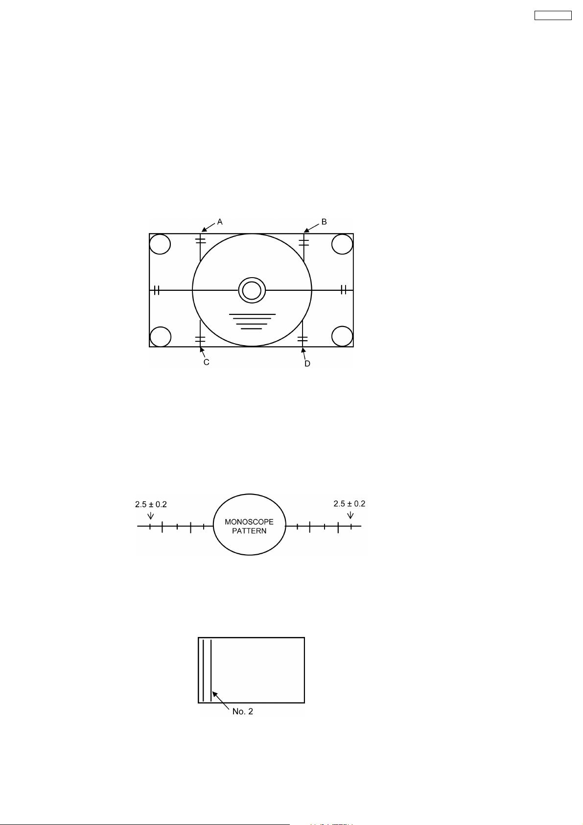
1. Confirmation of deflection setting, if not in spec, touch up as below :(Service 3)
A) For 60 Hz (4:3 only) :
a. Adjustment of 60 Hz V-CENTER
a. Receive the monoscope pattern (US13).
b. Adjust V-POS 60 Hz offset so that centre of monoscope pattern is at CRT centre.
b. Adjustment 60 Hz V-AMP
a. Receive the monoscope pattern (US13).
b. Adjust V-AMP 60 Hz offset so that
C, D (Fig. 3) is 2.0 ± 0.1
A, B (Fig. 3) is 2.0 ± 0.1
TX-21RX20T
Fig. 3
c. Adjustment of 60 Hz H-CENTER
a. Receive the monoscope pattern (US13).
b. Adjust H-POS 60 Hz offset so that horizontal position is at centre of CRT.
d. Adjustment of 60 Hz H-AMP
a. Receive the monoscope pattern (US13).
b. Adjust H-AMP 60 Hz offset so that both edges are within 2.5 ± 0.2. Refer to Fig. 1.
c. Touch up if necessary.
Fig. 1
e. EW ADJUSTMENT
a. Receive crosshatch pattern. (JA7)
b. Adjust the vertical line no. 2 to straight line (parabola) by EW-AMP1 60 Hz offset. (Fig. 3)
c. Touch up if necessary.
Fig. 3
17
Page 18
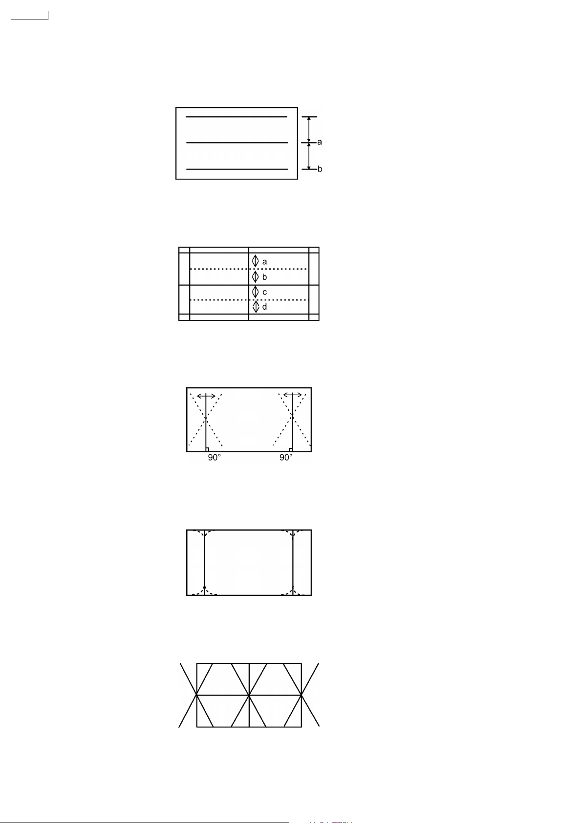
TX-21RX20T
B) For other Deflection touch up 50 & 60 Hz ; 4:3 & 16:9
1. Adjustment of V-Sym
a. Adjust V-SYM so that a=b in Fig. 1
2. Adjustment of V-LIN
a. Adjust V-LIN a=b=c=d in Fig. 2.
Fig. 1
Fig. 2
3. Adjustment of TRAPEZOID
a. Adjust the vertical line to straight line of both sides of vertical lines (trapezoid) in Fig. 3 by TRAPEZ 1.
Fig. 3
4. Adjustment of UPPER CORNER AND LOWER CORNER
a. Adjust the EW at corner in Fig. 4 by UPPER-CORNER and LOW- CORNER.
Fig. 4
5. Adjustment of ANGLE
a. Adjust ANGLE so that the vertical line is orthogonal to the horizontal line (Fig. 5).
Fig. 5
18
Page 19
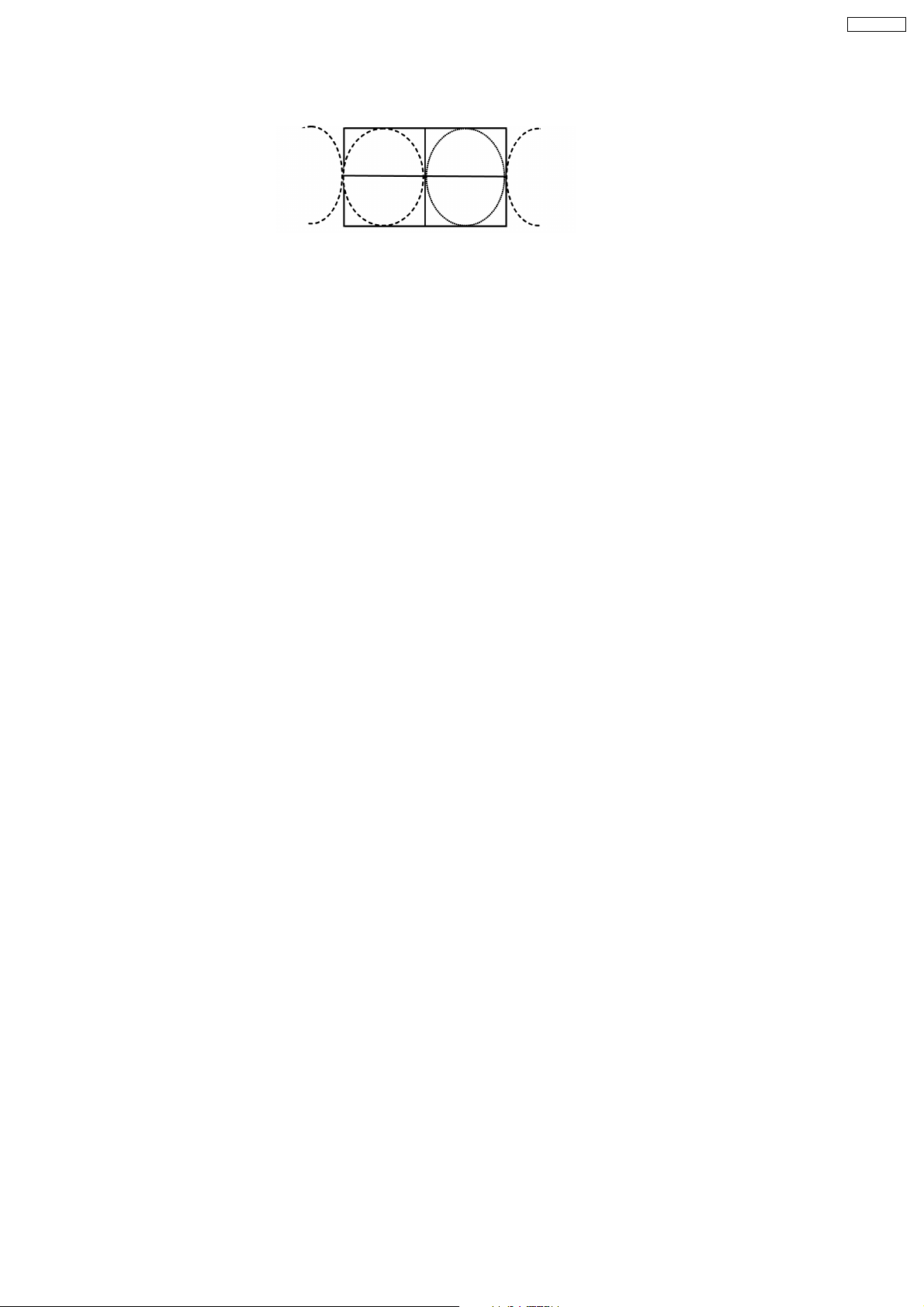
6. Adjustment of BOW
a. Adjust BOW so that the vertical lines are straight. (Fig. 6)
Fig. 6
TX-21RX20T
19
Page 20
TX-21RX20T
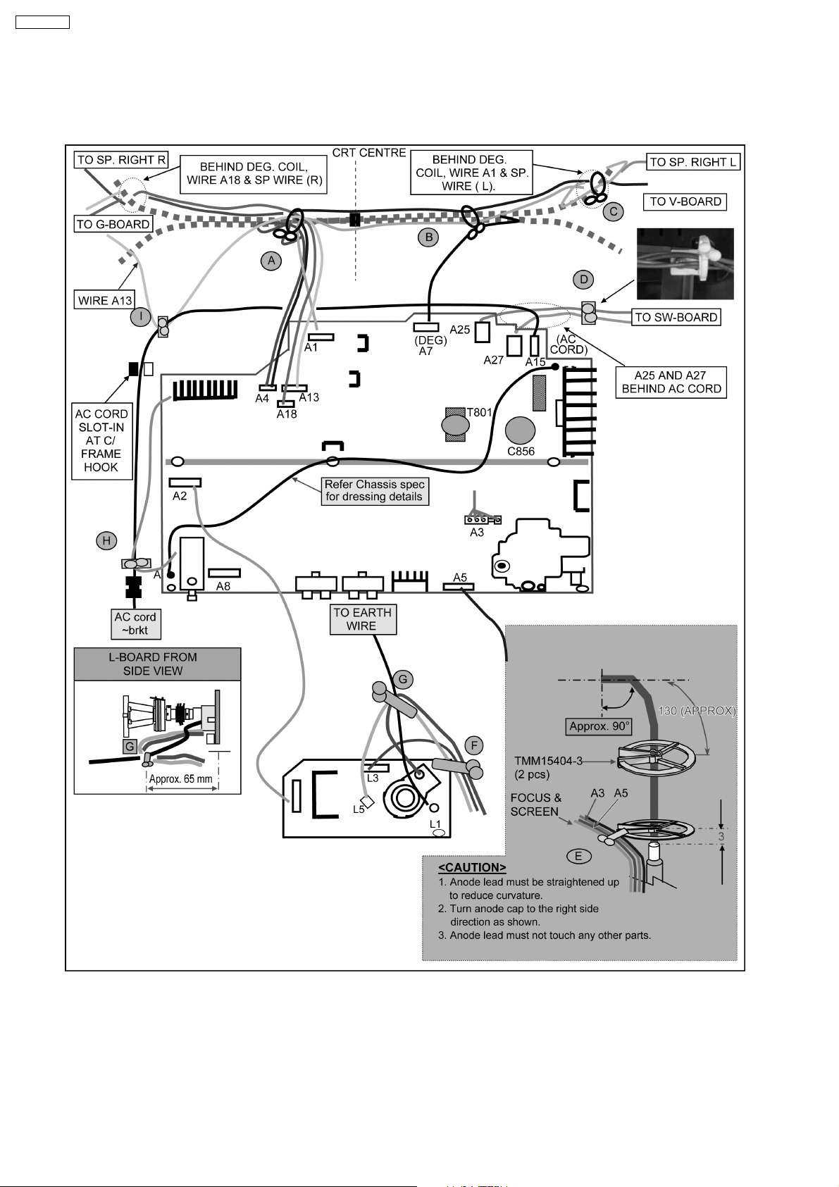
3 Location of Lead Wiring
3.1. Wire Dressing
20
Page 21
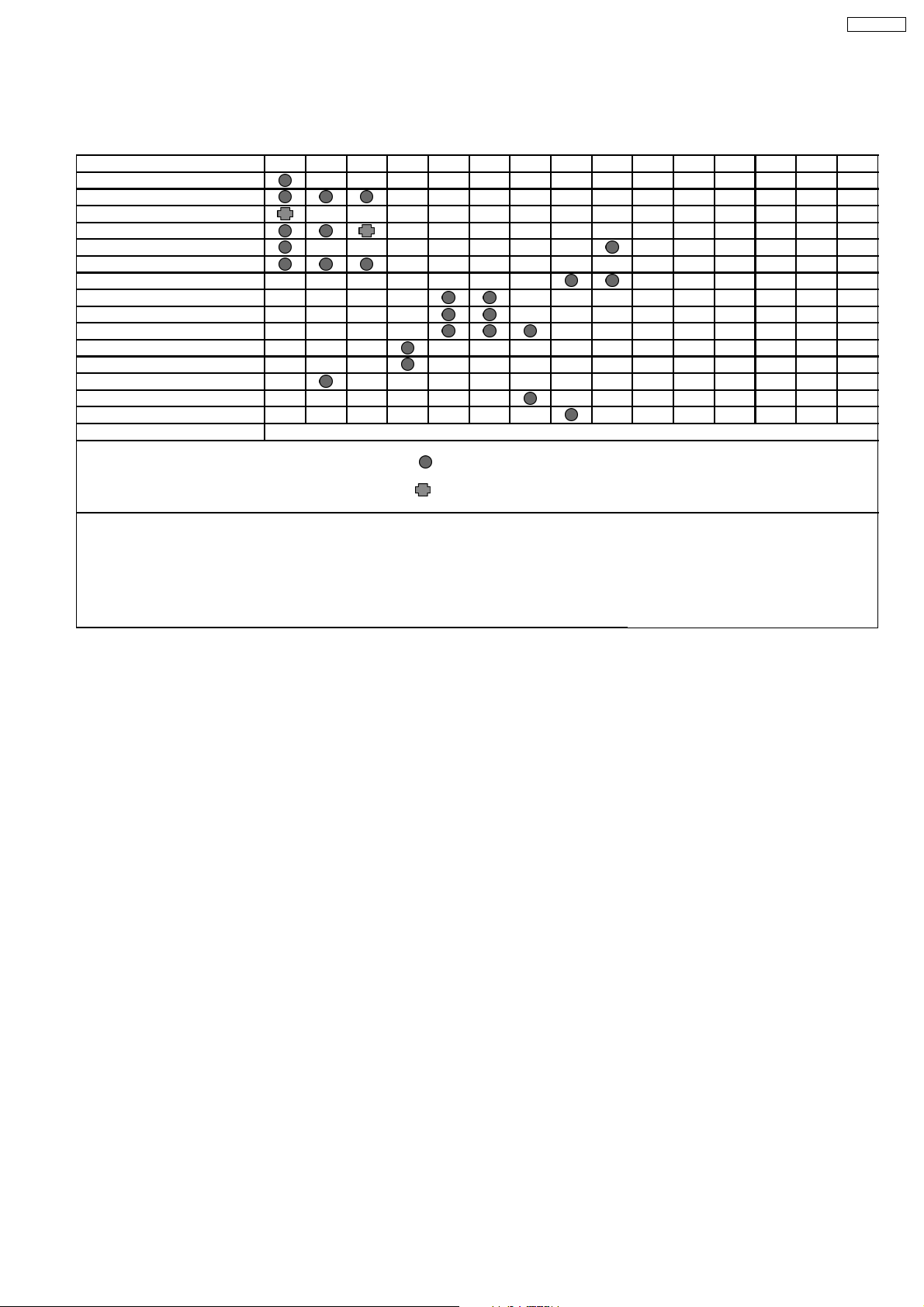
3.2. Wire Dressing and Connections
< CONNECTIONS >
LEAD \ CLAMPER A B C D E F G H I
A18 ~ G18
DEG COIL
SPEAKER (R)
SPEAKER (L)
A13 ~ G13)
A1 ~ V1
AC CORD
A5 ~ L3
A3
FOCUS & SCREEN
A27 ~ SW5
A25 ~ SW15
A7
L1
C~C
G20 ~ K20 WIRE MUST BE INSERTED AT G-BOARD AND K-B0ARD CONNECTORS.
= SINGLE CLAMP
TX-21RX20T
= DOUBLE CLAMP
< SAFETY CAUTION POINTS >
1. ALL LEADS MUST NOT TOUCH THE HIGH TEMPERATURE PARTS.
(HEAT SINK / FBT / POWER CIRCUIT)
2. DY LEAD MUST BE KEPT A DISTANCE (MINIMUM 10 mm) FROM FBT BODY.
3. ANODE LEAD MUST BE KEPT A DISTANCE (MINIMUM 10 mm) FROM OTHER PARTS.
4. AC CORD MUST BE INSERTED ACCORDING TO POLARITY AND COLOUR.
21
Page 22
TX-21RX20T
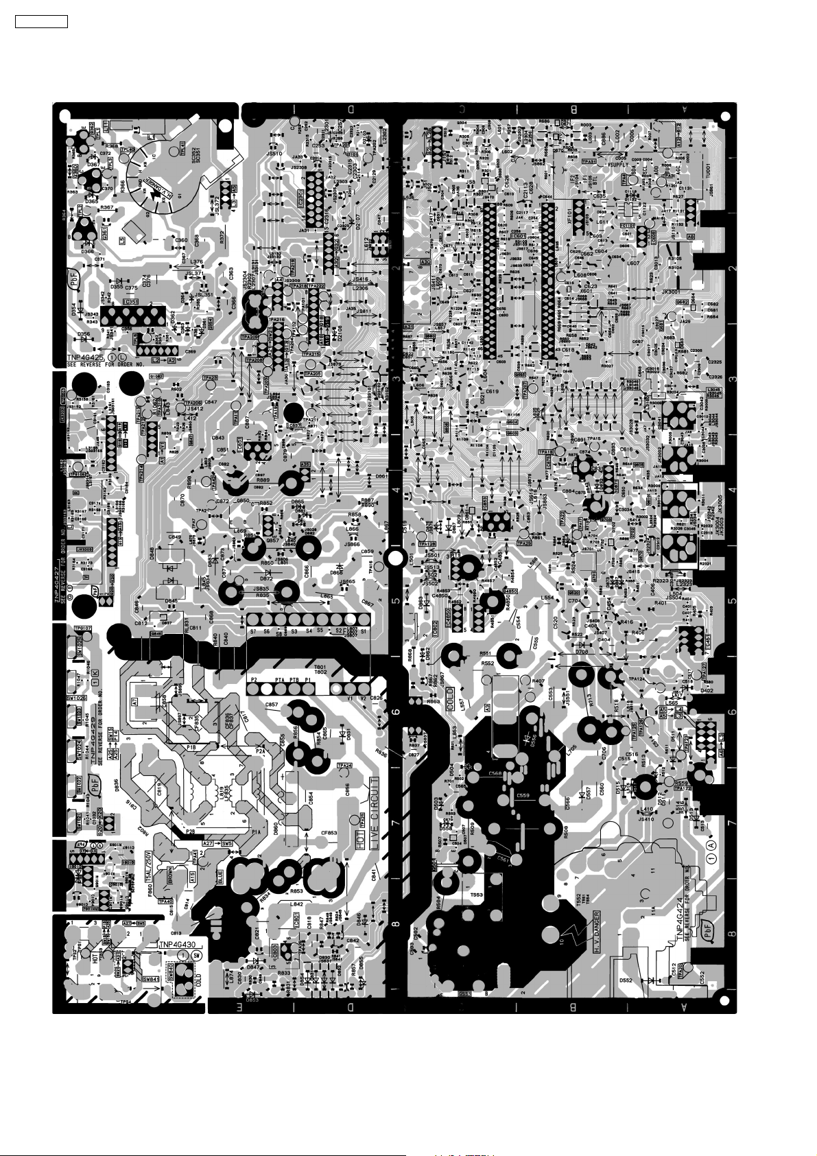
4 Conductor Views
22
Page 23
5 Schematic Diagram
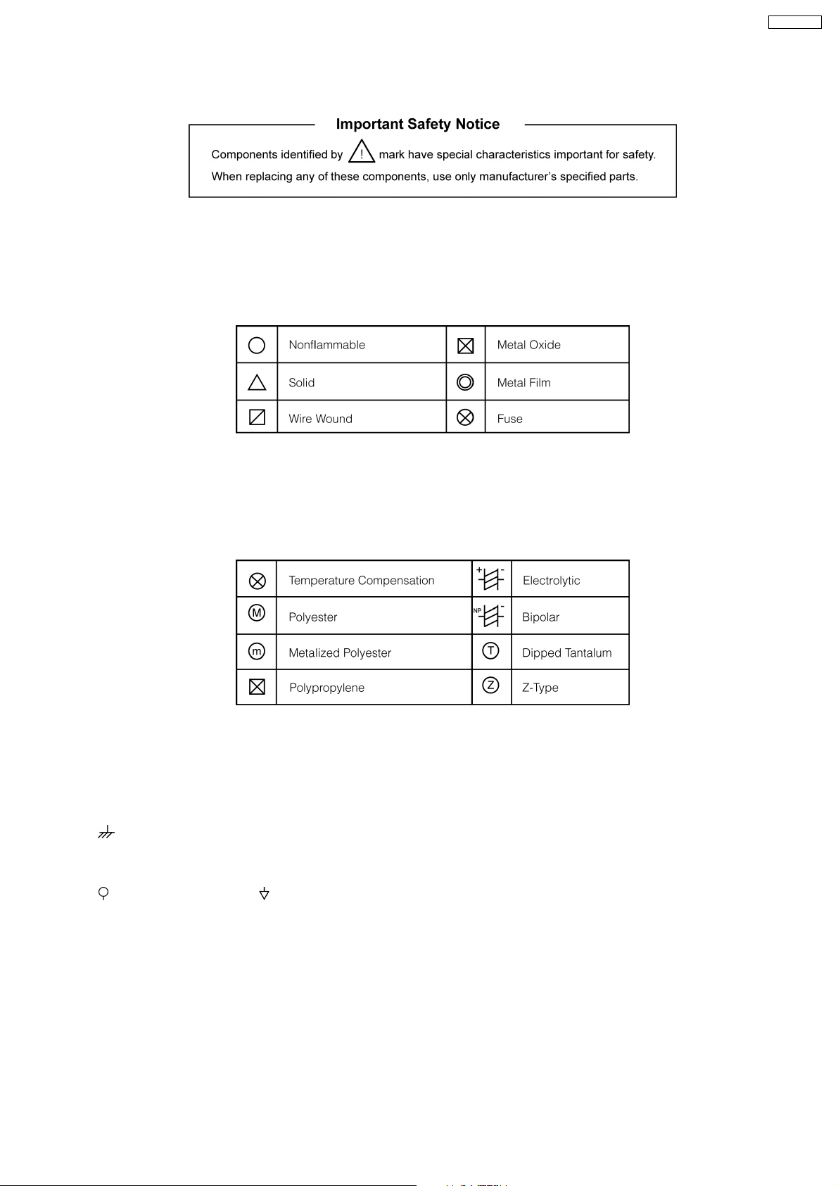
Notes :
1. Resistor
All resistors are carbon 1/4 W resistors unless marked as follows :
Unit of resistance is OHM (Ω) (K = 1 000 M = 1 000 000)
TX-21RX20T
2. Capacitor
All capacitors are ceramic 50 V capacitors unless marked as follows :
Unit of capacitance is µF unless otherwise noted.
3. Coil
Unit of inductance is µH, unless otherwise noted.
4. Test Point
: Test Point position
5. Earth Symbol
: Chassis Earth (Cold) : Line Earth (Hot)
6. Voltage Measurement
Voltage is measured using DC voltmeter.
Conditions of the measurement are the following :
Power Source....................AC AUTO 110-240 V, 50/60 Hz
Receiving Signal................Colour Bar signal (RF)
All customer’s controls.......Maximum positions
7. Number in red circle indicates waveform number.
(See waveform pattern table)
23
Page 24
TX-21RX20T
8. When an arrow mark ( ) is found, connection is easily found from the direction of the arrow.
9.
: Indicates the major signal flow.
10. This schematic diagram is the latest at the time of printing and subject to change without notice.
Remarks :
The Power Circuit contains a circuit area which uses a separate power supply to isolate the earth connection.
The circuit is defined by HOT and COLD indications in the schematic diagram.
Take the following precautions:
All circuits, except the Power Circuit are cold.
Precautions:
a. Do not touch the hot part or the hot and cold parts at the same time or you may be shocked.
b. Do not short-circuit the hot and cold circuits or a fuse may blow and parts may break.
c. Do not connect an instrument such as an oscilloscope to the hot and cold circuits simultaneously or a fuse may blow.
Connect the earth of instruments to the earth connection of the circuit being measured.
d. Make sure to disconnect the power plug before removing the chassis.
24
Page 25
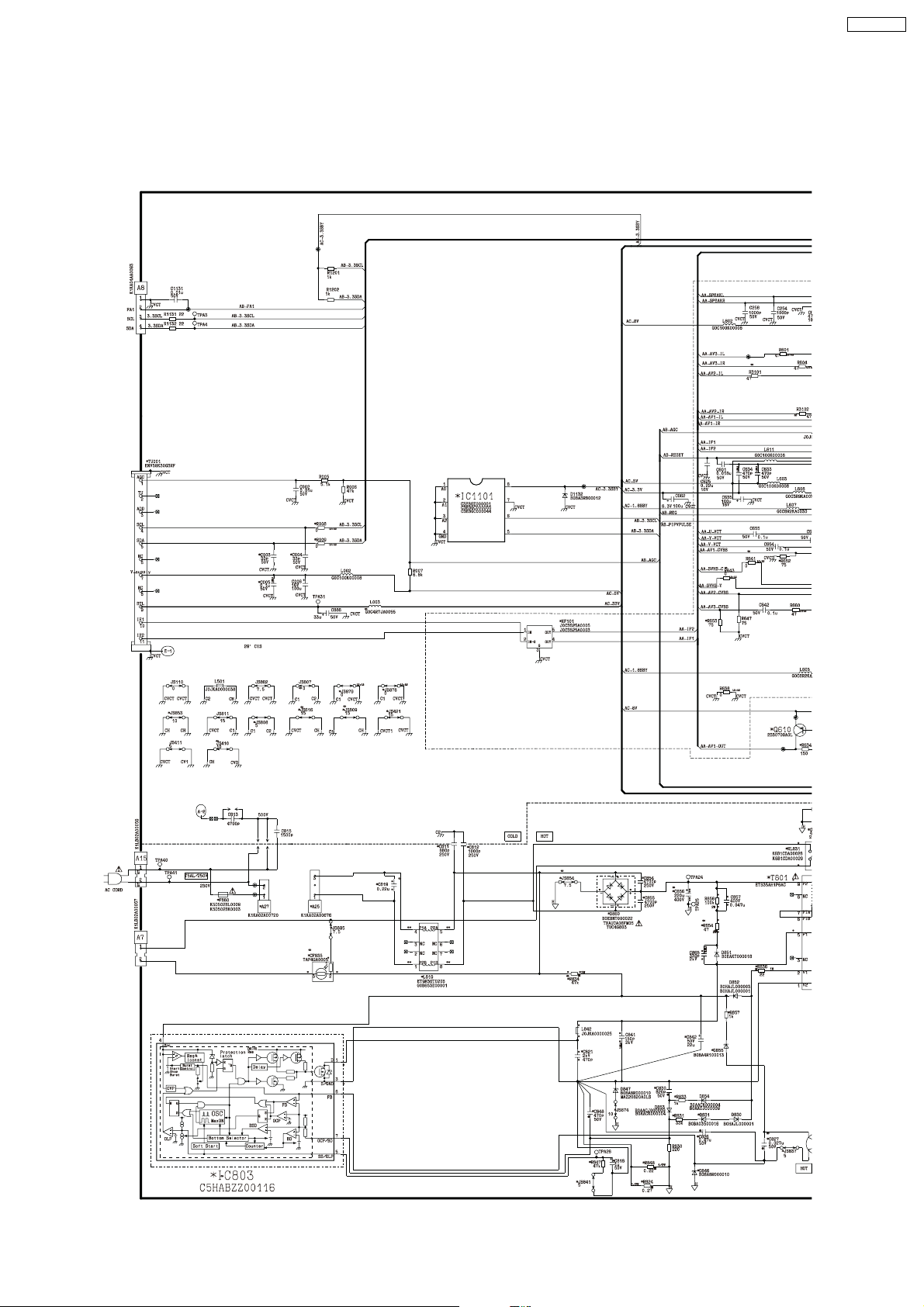
5.1. A Board
5.1.1. A Board (1/5)
TX-21RX20T
<1A>
<2A>
<3A>
<4A>
<5A>
<6A>
<7A>
25
<8A>
Page 26
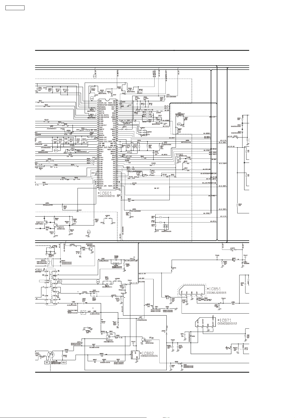
TX-21RX20T
5.1.2. A Board (2/5)
<1A>
<2A>
<3A>
<4A>
<5A>
<1B>
<2B>
<6A>
<7A>
<3B>
<4B>
<5B>
<8A>
<6B>
<7B>
26
Page 27
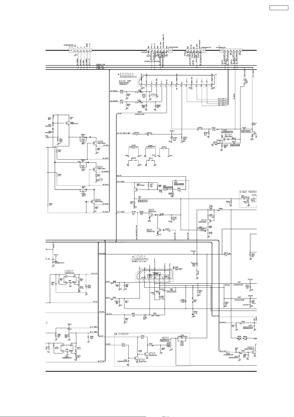
5.1.3. A Board (3/5)
TX-21RX20T
<1B>
<2B>
<1C>
<2C>
<3B>
<4B>
<5B>
<3C>
<4C>
<5C>
<6C>
<7C>
<6B>
<7B>
<8C>
27
Page 28
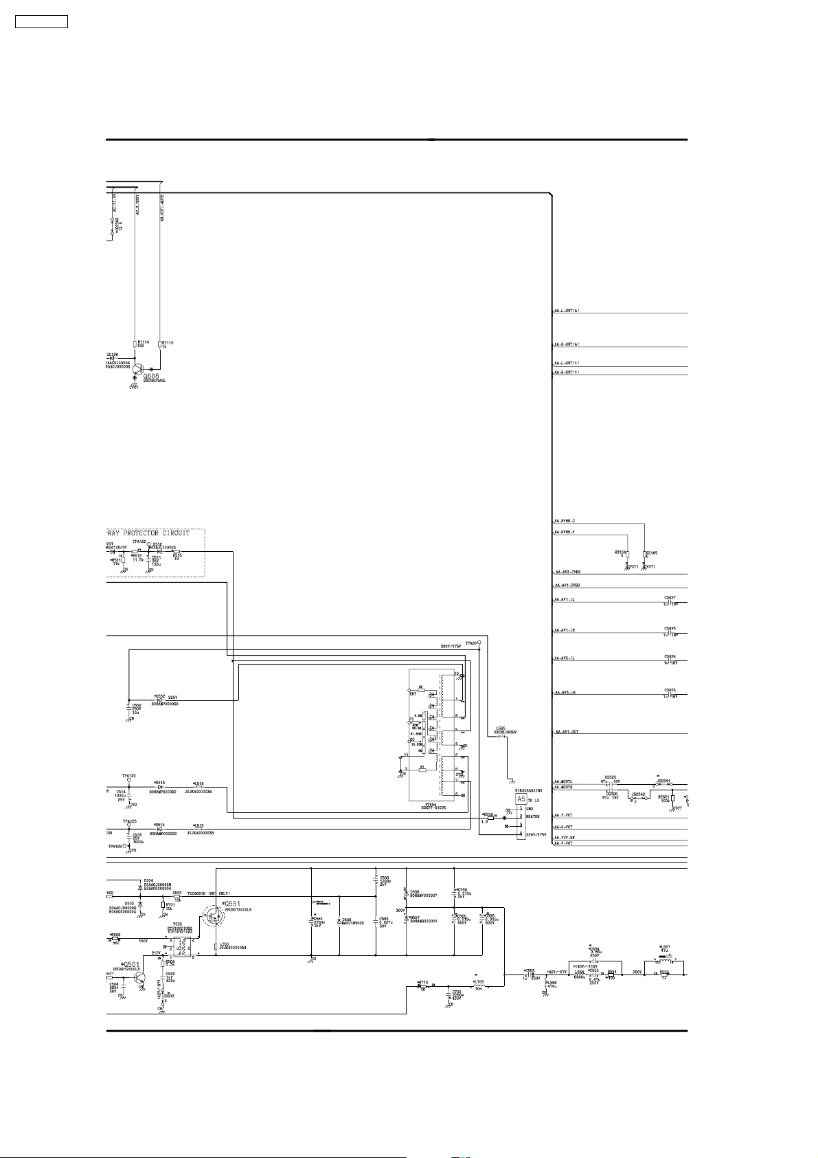
TX-21RX20T
5.1.4. A Board (4/5)
<1C>
<2C>
<1D>
<2D>
<3D>
<3C>
<4C>
<5C>
<6C>
<7C>
<4D>
<5D>
<6D>
<7D>
<8C>
<8D>
<9D>
28
Page 29
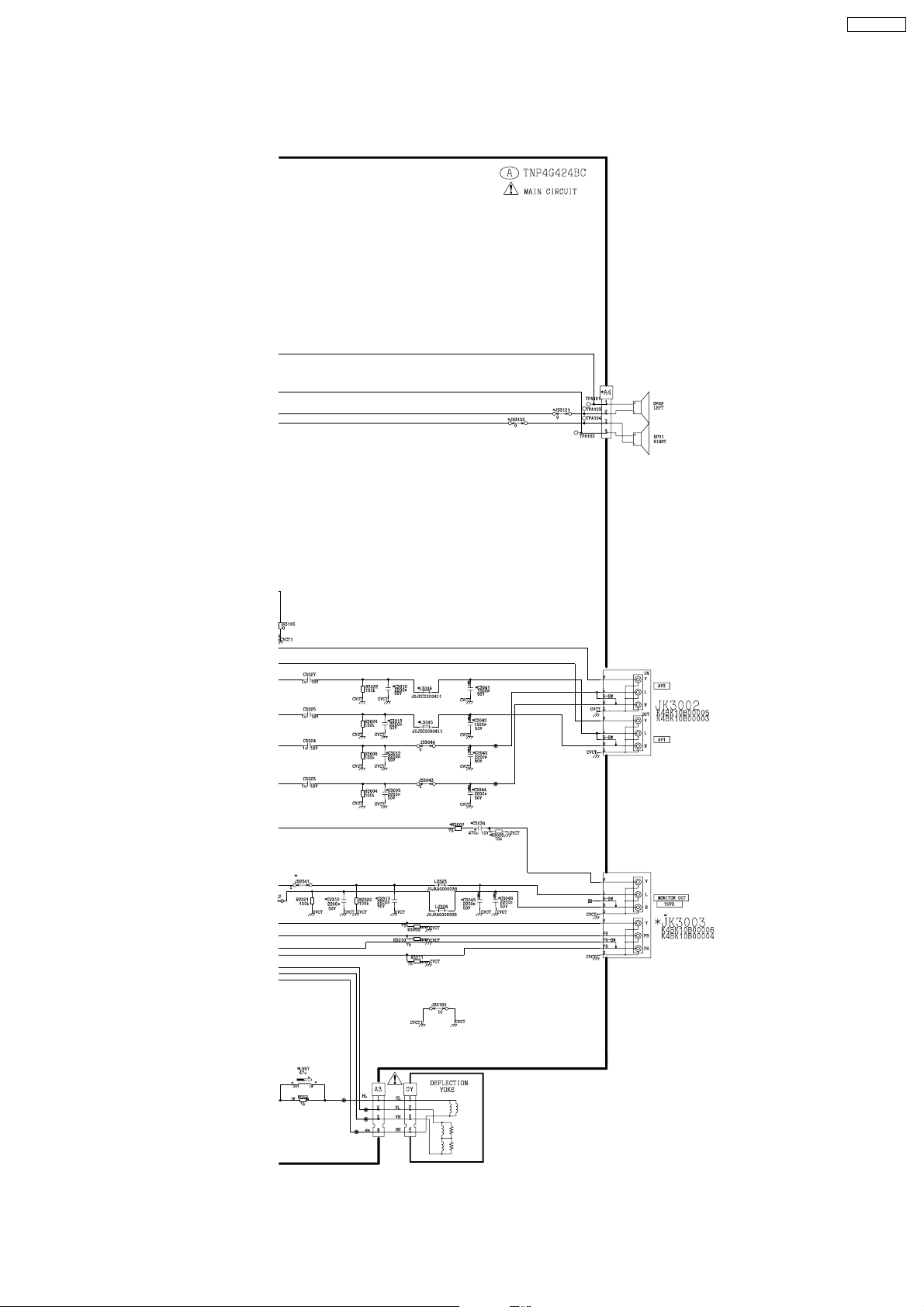
5.1.5. A Board (5/5)
<1D>
<2D>
<3D>
TX-21RX20T
<4D>
<5D>
<6D>
<7D>
<8D>
<9D>
29
Page 30
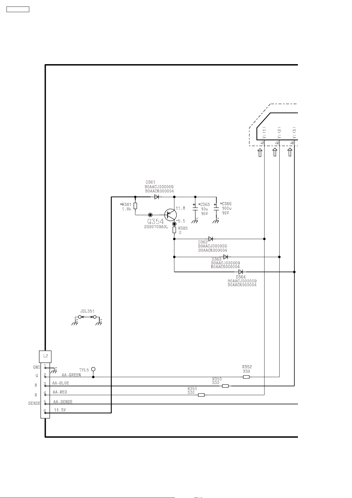
TX-21RX20T
5.2. L Board
5.2.1. L Board (1/3)
<1A>
<2A>
<3A>
30
<4A>
<5A>
Page 31
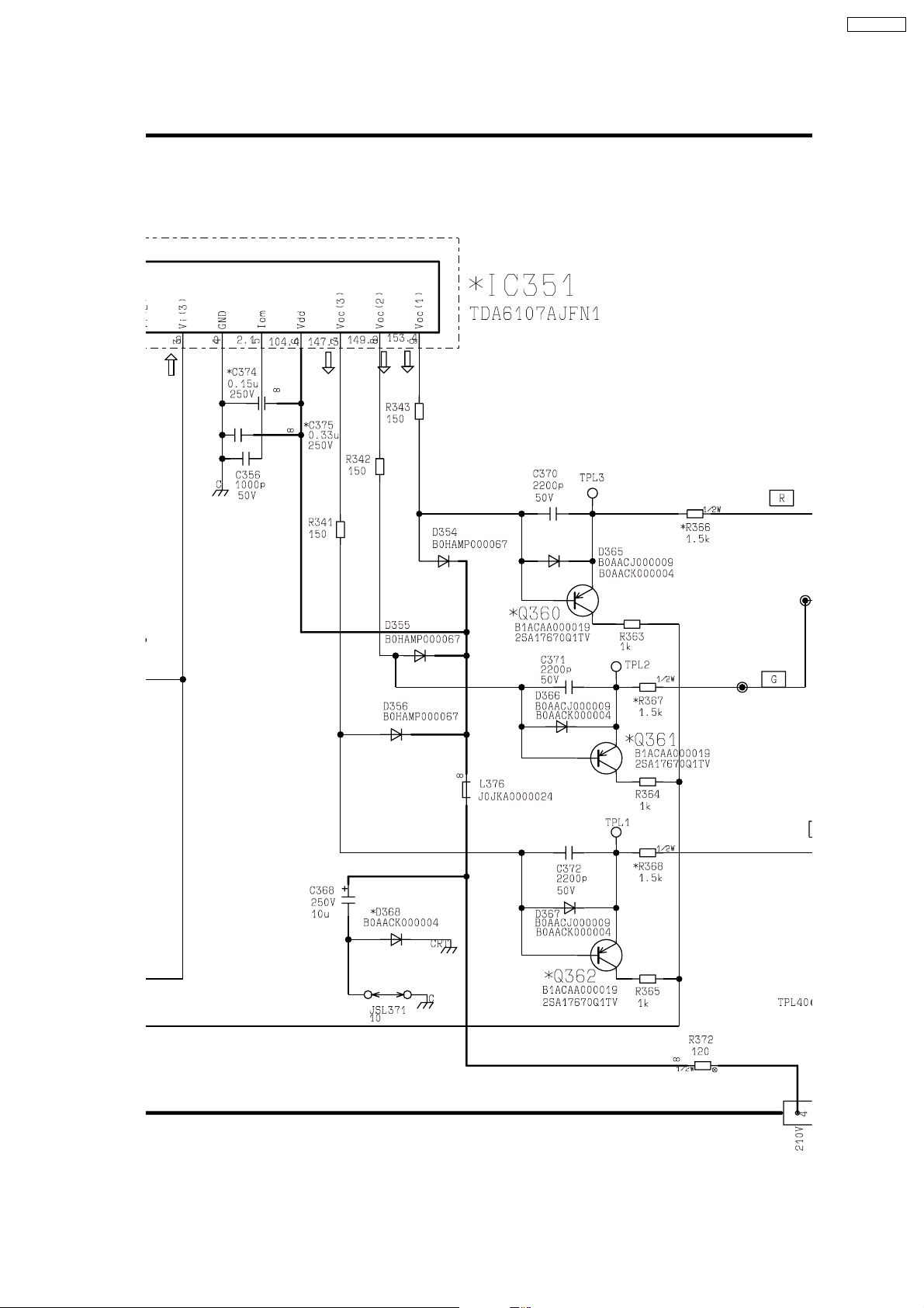
5.2.2. L Board (2/3)
TX-21RX20T
<1A>
<2A>
<3A>
<1B>
<2B>
<4A>
<5A>
<3B>
<4B>
31
Page 32
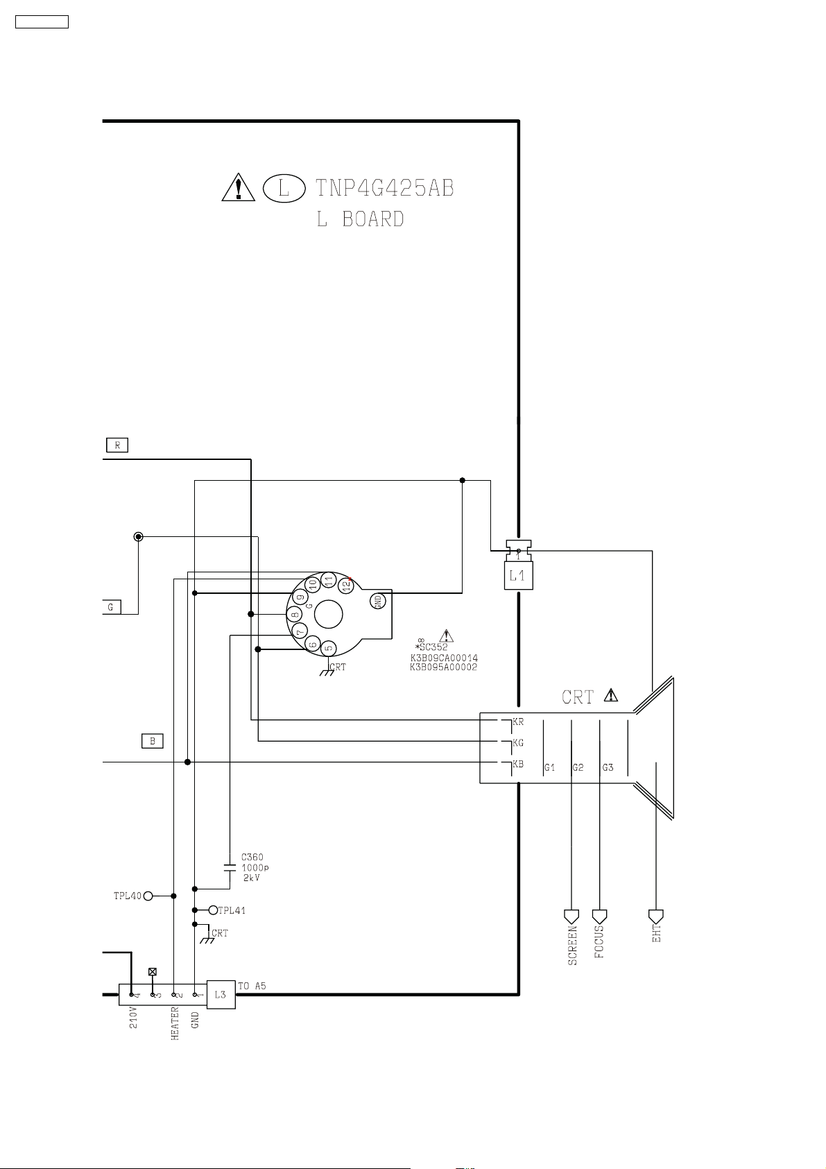
TX-21RX20T
5.2.3. L Board (3/3)
<1B>
<2B>
<3B>
<4B>
32
Page 33
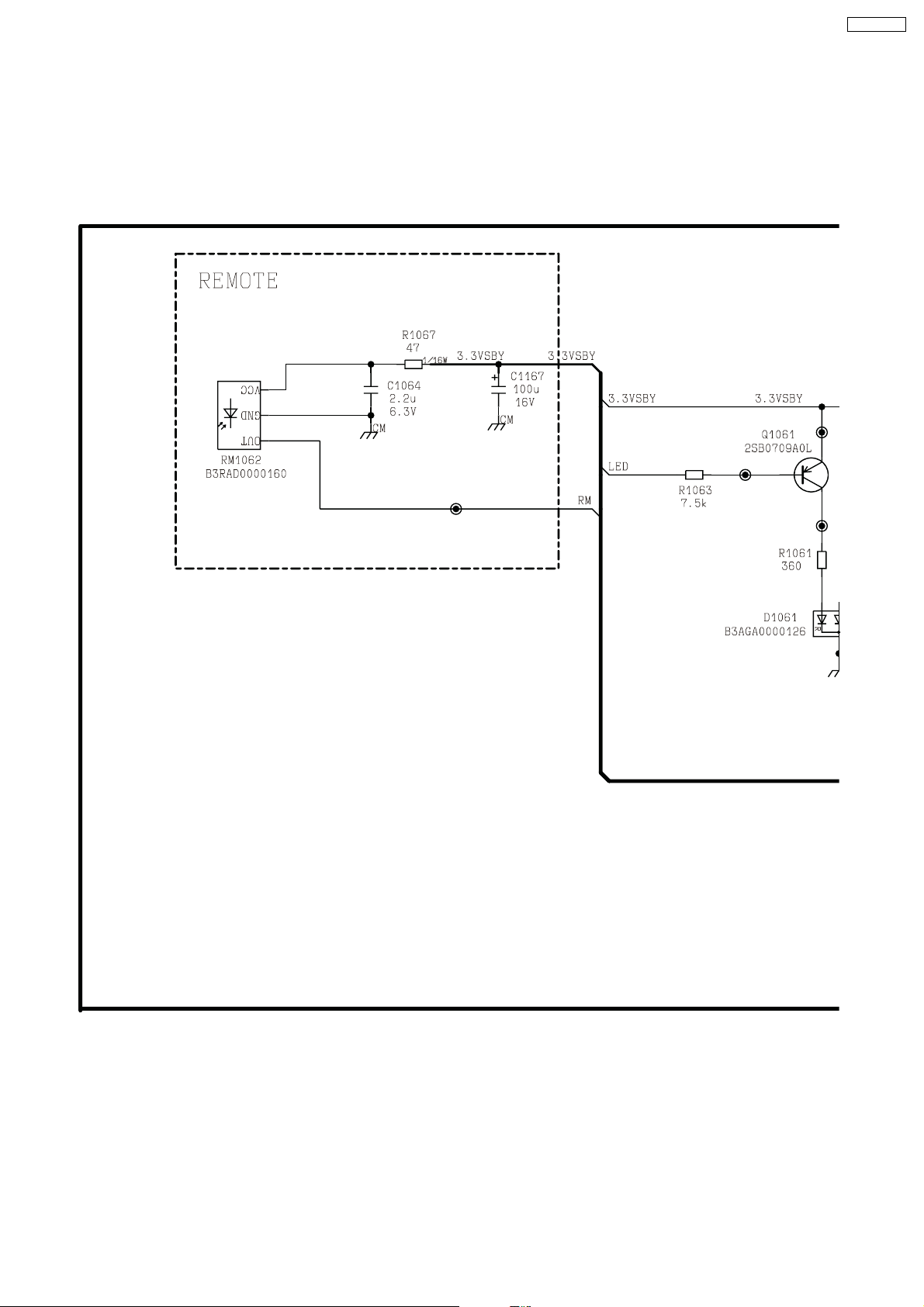
5.3. V Board
5.3.1. V Board (1/2)
TX-21RX20T
<1A>
<2A>
<3A>
<4A>
33
Page 34
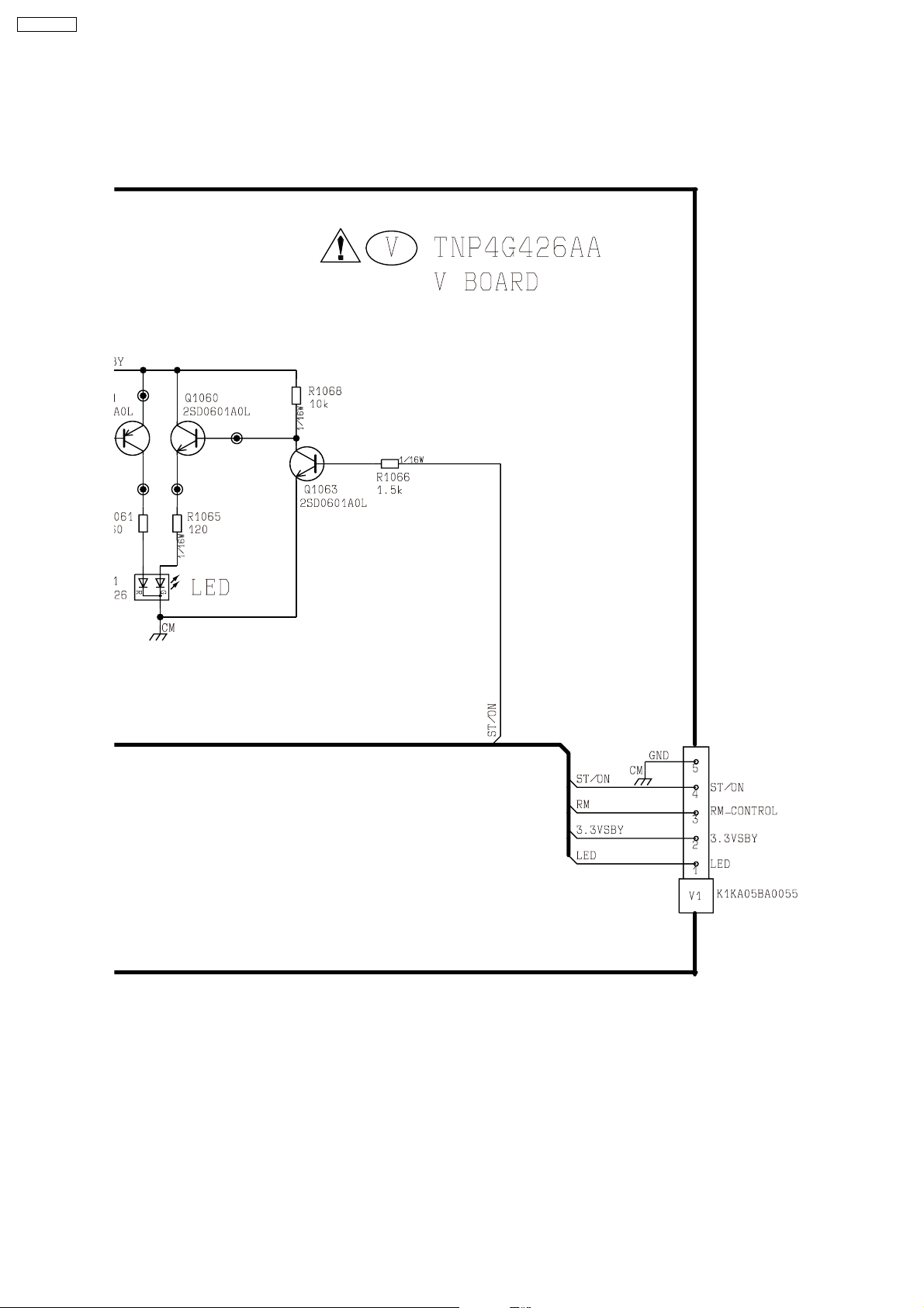
TX-21RX20T
5.3.2. V Board (2/2)
<1A>
<2A>
<3A>
<4A>
34
Page 35
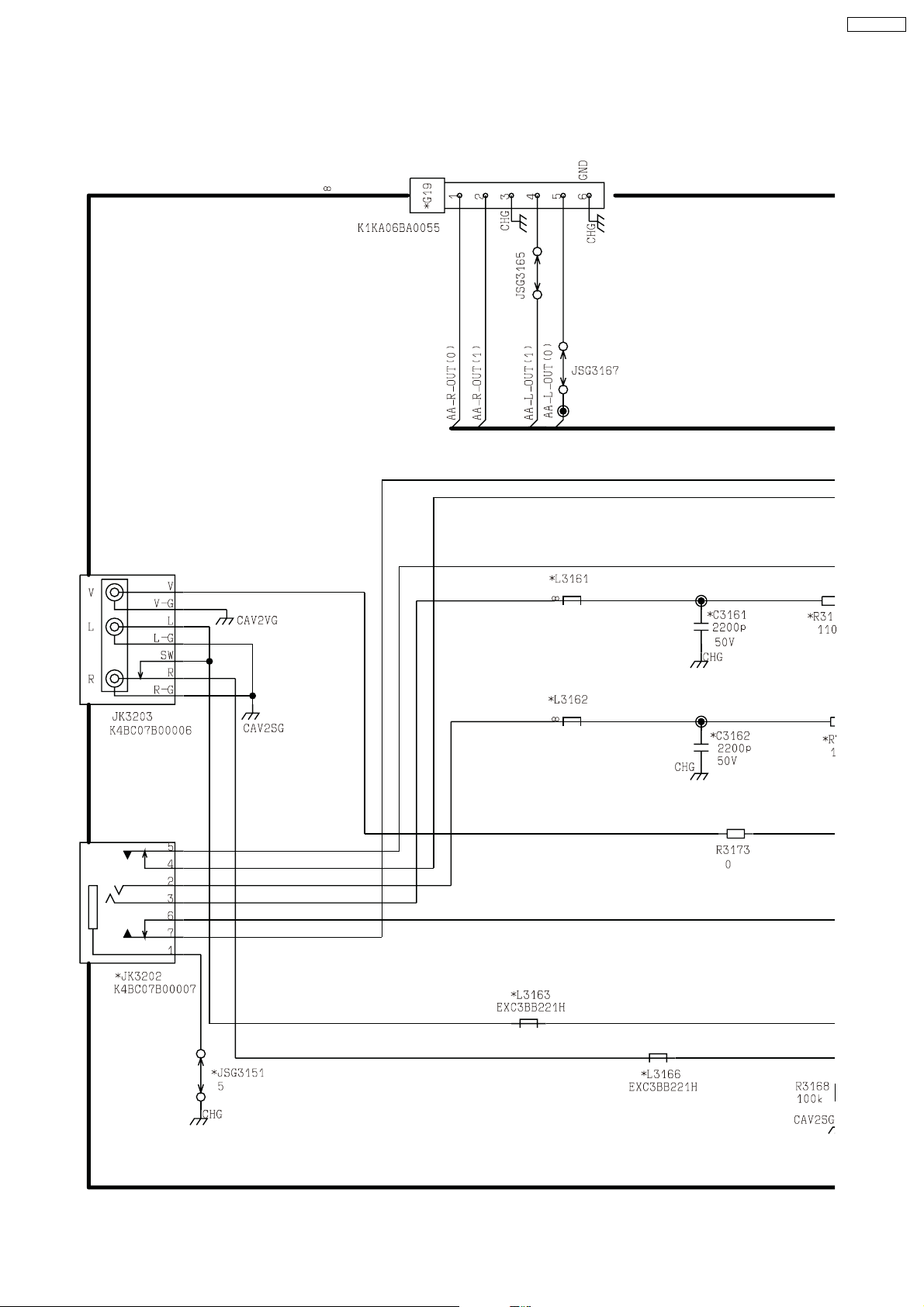
5.4. G Board
5.4.1. G Board (1/2)
TX-21RX20T
<1A>
<2A>
<3A>
<4A>
<5A>
<6A>
<7A>
35
<8A>
<9A>
Page 36
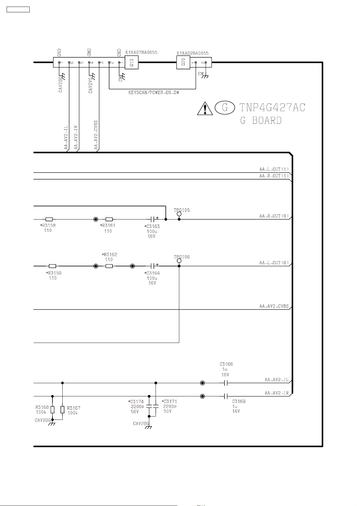
TX-21RX20T
5.4.2. G Board (2/2)
<1A>
<2A>
<3A>
<4A>
<5A>
<6A>
<7A>
<8A>
<9A>
36
Page 37
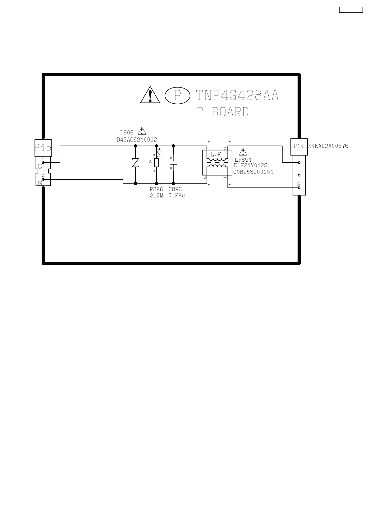
5.5. P Board
5.5.1. P Board
TX-21RX20T
37
Page 38
TX-21RX20T
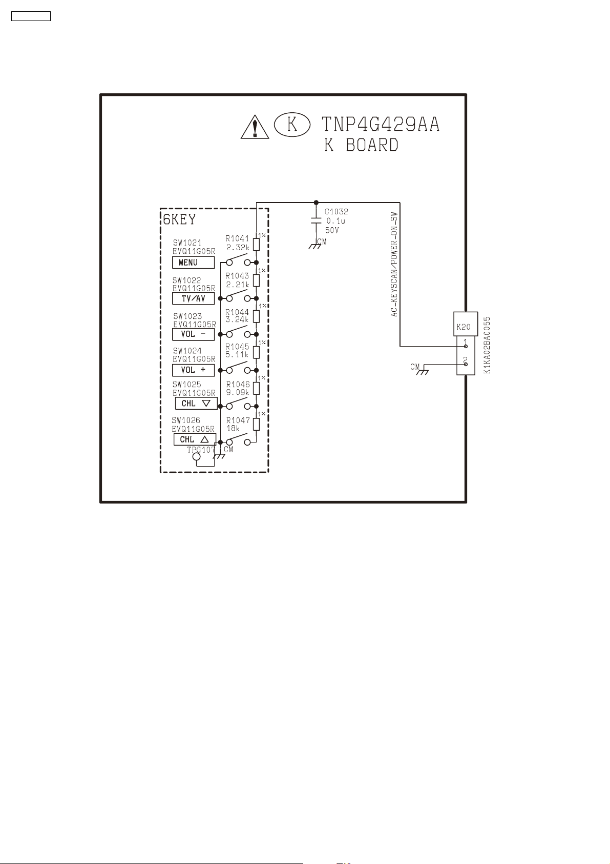
5.6. K Board
5.6.1. K Board
38
Page 39
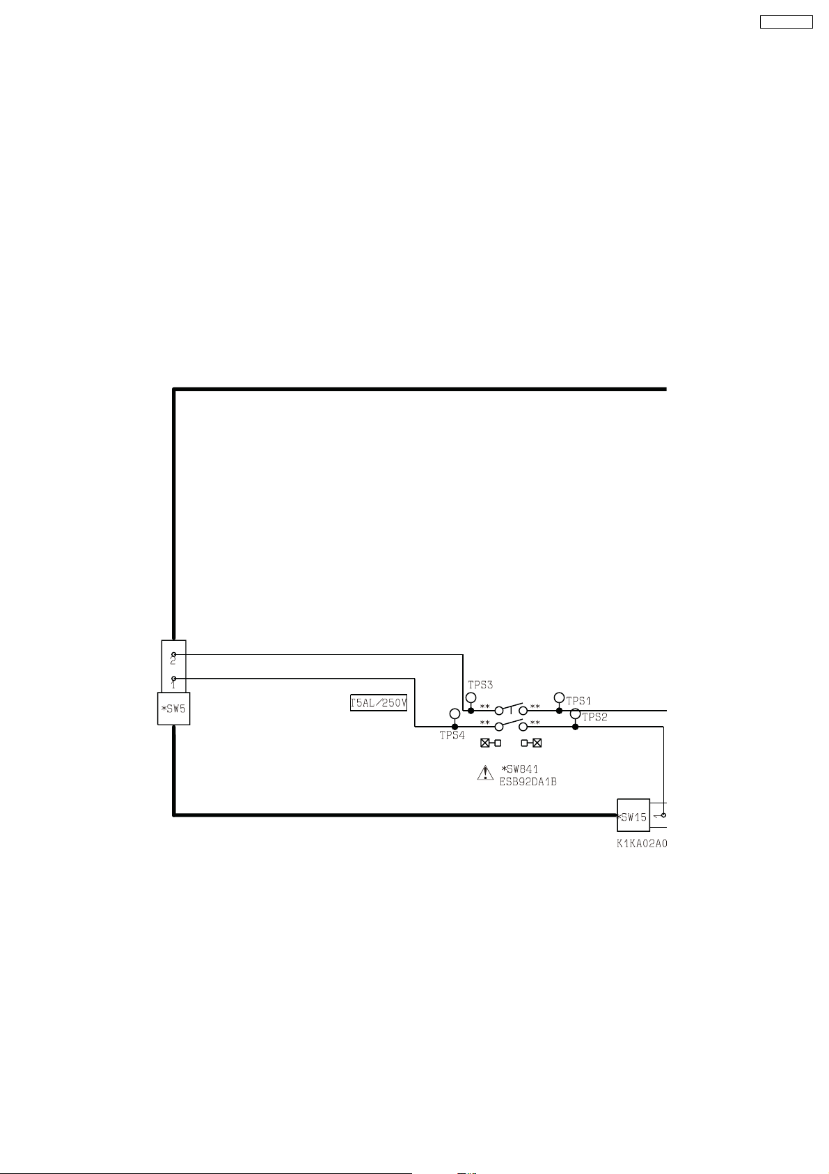
5.7. SW Board
5.7.1. SW Board (1/2)
TX-21RX20T
<1A>
<2A>
<3A>
39
Page 40
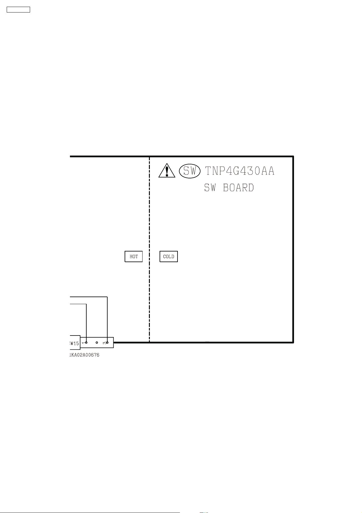
TX-21RX20T
5.7.2. SW Board (2/2)
<1A>
<2A>
<3A>
40
Page 41
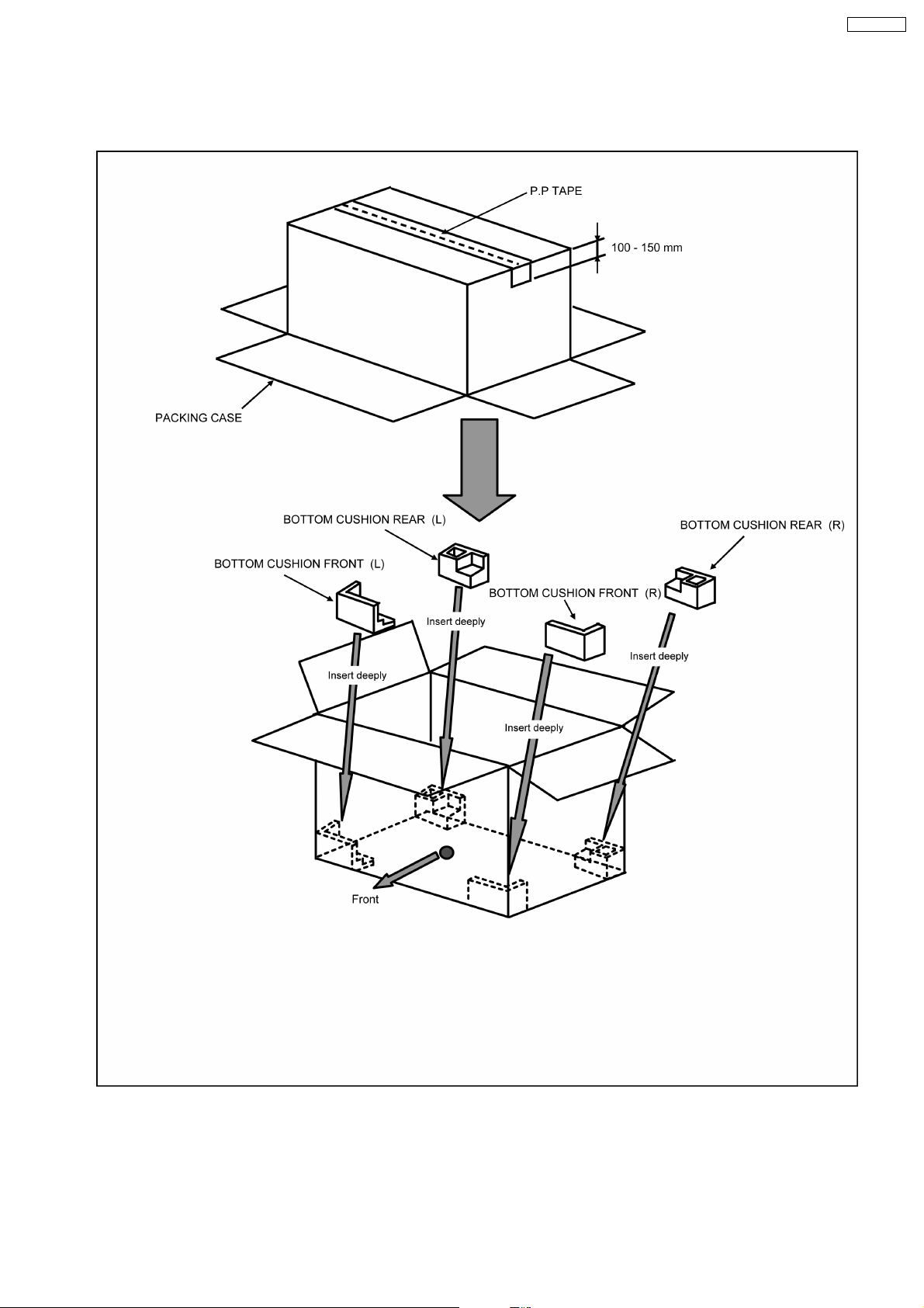
6 Parts Locations
6.1. Packing Exploded View - A
TX-21RX20T
41
Page 42
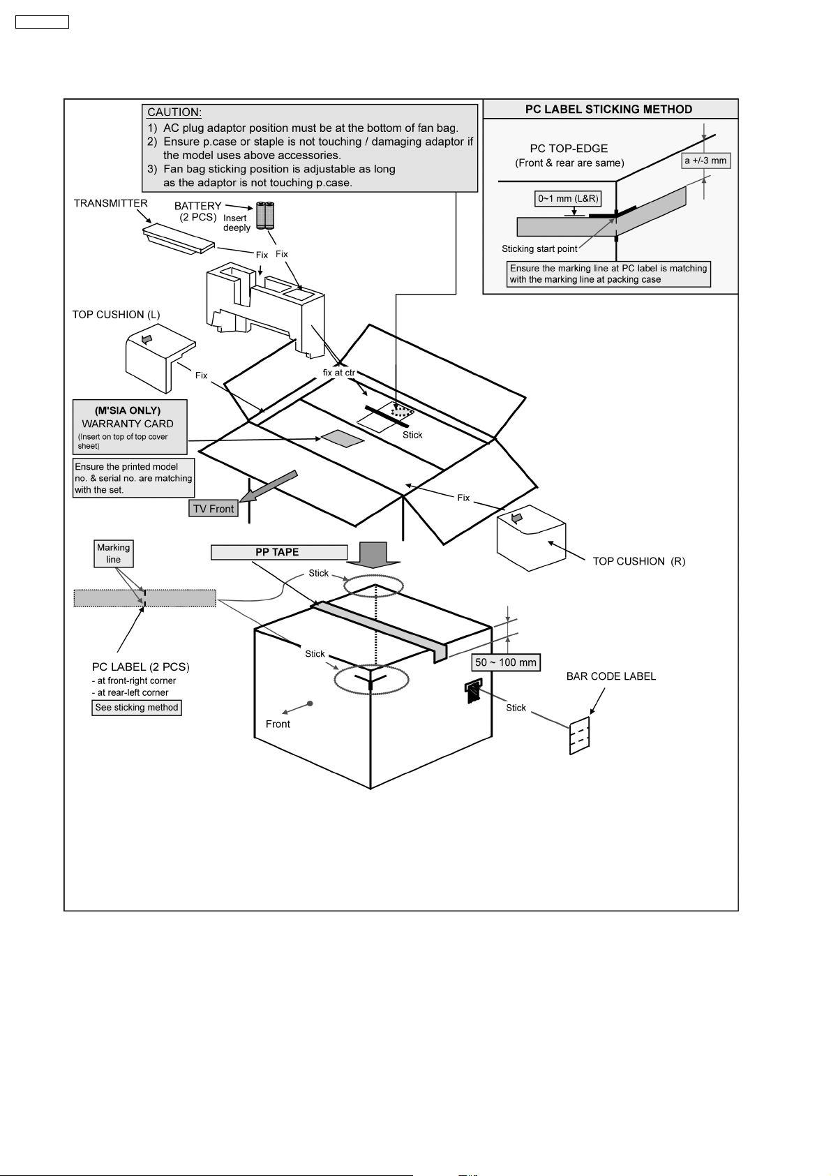
TX-21RX20T
6.2. Packing Exploded View - B
42
Page 43
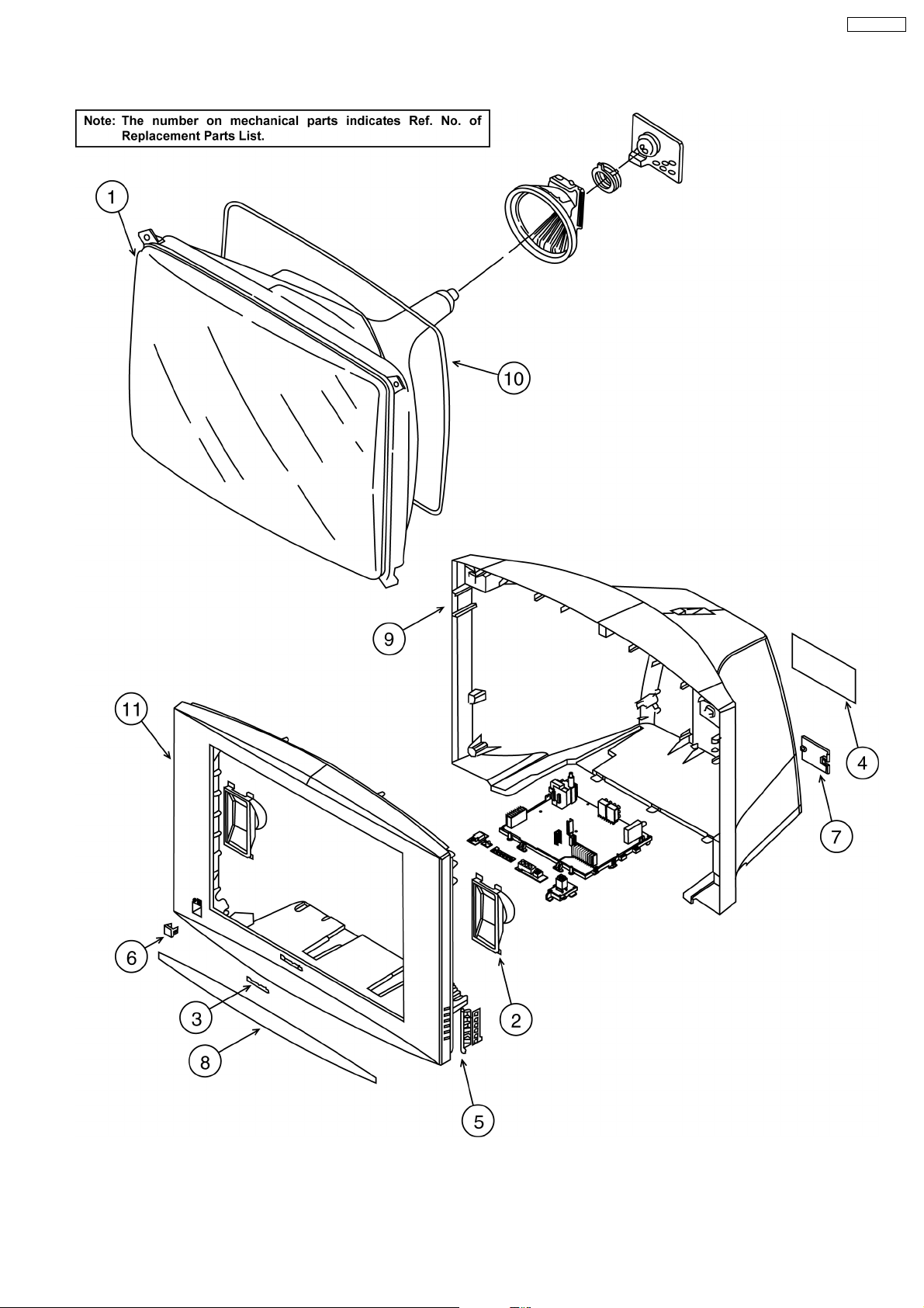
6.3. Parts Locations
TX-21RX20T
43
Page 44
TX-21RX20T
7 Replacement Parts List
Note : Printed circuit board assembly with “NLA” is no longer available after production discontinuation of the complete set.
Abbreviation of part name and description
1. Resistor
Example :
ERD25TJ104 C 100 kΩ, J, 1/4 W
Type Allowance
C: Carbon F: ±1%
F: Fuse G: ±2%
M: Metal Oxide
Metal Film
S: Solid M: ± 20%
W: Wire Wound
J:K:±5%
± 10%
2. Capacitor
Example :
ECKF1H103ZF C 0.01 µF, Z,50V
Type Allowance
C: Carbon C: ± 0.25 pF
F: Electrolytic D: ± 0.5 pF
P: Polyester
Polypropylene
S: Tantalum J: ±5%
F:G:±1pF
K: ± 10%
L: ± 15%
M: ± 20%
P: ± 100%, -0%
Z: ± 80%, -20%
±3%
44
Page 45
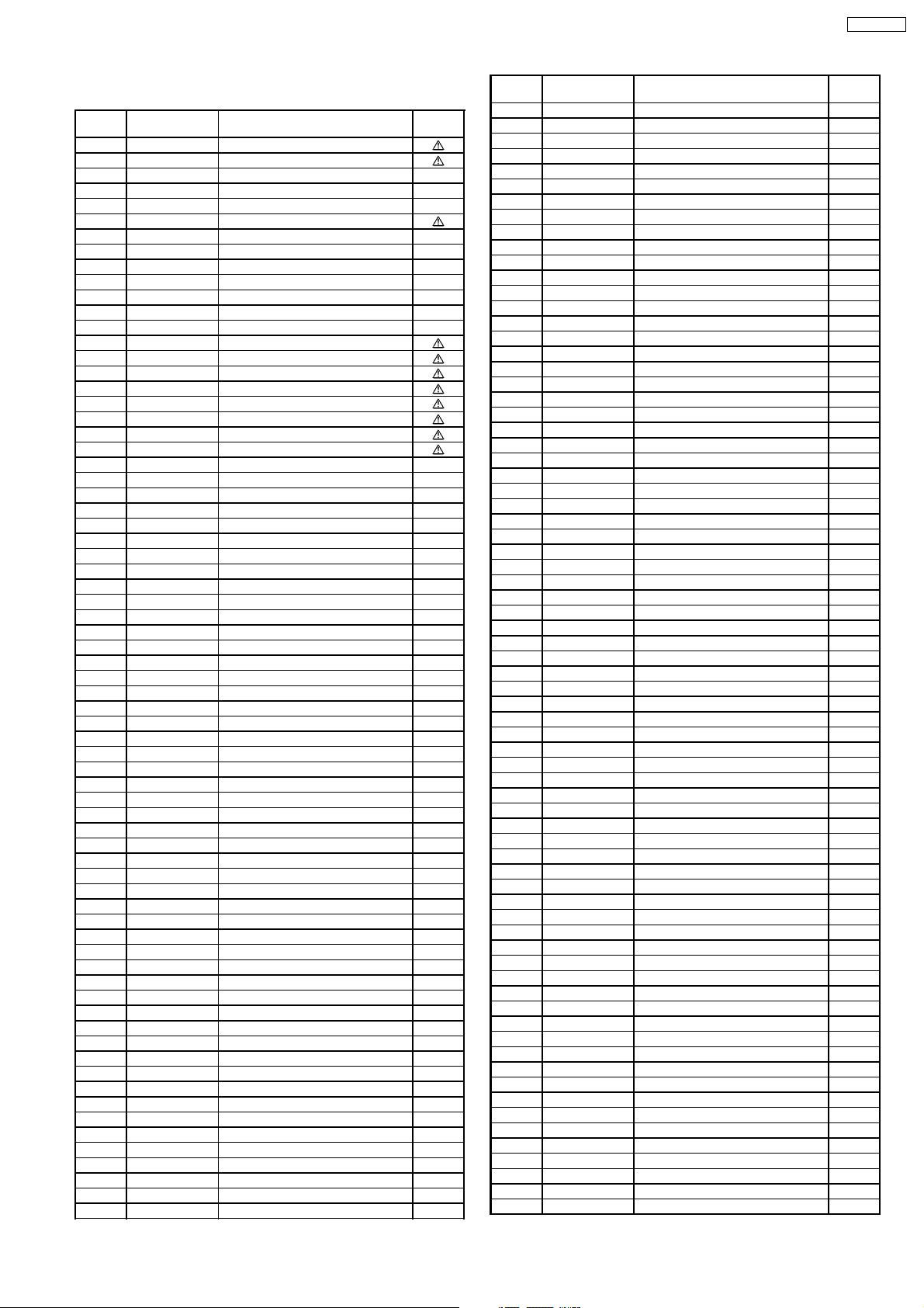
TX-21RX20T
7.1. Replacement Parts List
Ref.
No.
1 A51QGV991X31 ITC CRT
2 L0AA11C00011 SPEAKER
3 TBM4G3021 PANASONIC BADGE
4 TBM4GC089 MODEL NAME PLATE
5 TBX4GA00401 6 KEY BUTTON
6 TBX4GA00502 POWER SWITCH BUTTON
7 TKP4G11745 AC CORD BRACKET
8 TKR4GA00301A ORNAMENT PANEL (BOTTOM)
9 TKU4GC00301 BACK COVER
10 TLK4G9102J-S DEGAUSSING COIL
NLA TNP4G424BC A BOARD
NLA TNP4G425AB L BOARD
NLA TNP4G426AA V BOARD
NLA TNP4G427AC G BOARD
NLA TNP4G428AA P BOARD
NLA TNP4G429AA K BOARD
NLA TNP4G430AA SW BOARD
11 TTY4GA0015 CABINET ASSY
C002 F1H1H103A975 C 0.01UF,Z, 50V
C003 ECJ1VC1H330J C 33PF, J, 50V
C004 ECJ1VC1H330J C 33PF, J, 50V
C005 ECJ1VF1H104Z C 0.1UF, Z, 50V
C006 F2A1C101A310 E 100UF, 16V
C1032 ECJ2VF1H104Z C 0.1UF, Z, 50V
C1064 ECJ2FB0J225K C 2.2UF, J, 6.3V
C1103 F1J1H103A590 C 0.01UF, J, 50V
C1131 F1J1H103A590 C 0.01UF, J, 50V
C1142 ECJ1VF1H104Z C 0.1UF, Z, 50V
C1167 F2A1C101A310 E 100UF, 16V
C2113 F2A1H3R3A317 E 3.3UF, 50V
C2117 ECJ1VF1H104Z C 0.1UF, Z, 50V
C2129 F2A1C221A338 E 220UF, 16V
C2303 F2A1H4R7A317 E 4.7UF, 50V
C2312 ECJ2VC1H222J C 2200PF, J, 50V
C2313 ECJ2VC1H222J C 2200PF, J, 50V
C2314 F2A1E101A273 E 100UF, 25V
C2315 F2A1E471A299 E 470UF, 25V
C2316 ECQV1H104JL P 0.1UF, J, 50V
C2321 F1J1H102A018 E 1000UF, 50V
C2322 F1J1H102A018 E 1000UF, 50V
C2325 F2A1C470A310 E 47UF, 16V
C2326 F2A1C470A310 E 47UF, 16V
C253 ECA1HEN2R2B E 1000UF, 50V
C254 F1J1H102A018 E 1000UF, 50V
C257 ECA1HEN2R2B E 2.2UF, 50V
C258 F1J1H102A018 E 1000UF, 50V
C3005 ECJ2VC1H222J C 2200PF, J, 50V
C3012 ECJ2VC1H222J C 2200PF, J, 50V
C3016 ECJ2VC1H222J C 2200PF, J, 50V
C3018 ECJ2VC1H222J C 2200PF, J, 50V
C3023 ECJ1VF1C105Z C 1UF, Z, 16V
C3024 ECJ1VF1C105Z C 1UF, Z, 16V
C3025 ECJ1VF1C105Z C 1UF, Z, 16V
C3027 ECJ1VF1C105Z C 1UF, Z, 16V
C3034 F2A1A471A274 E 470UF, 10V
C3041 ECJ2VC1H152J C 1500PF, J, 50V
C3042 ECJ2VC1H152J C 1500PF, J, 50V
C3043 ECJ2VC1H222J C 2200PF, J, 50V
C3044 ECJ2VC1H222J C 2200PF, J, 50V
C3045 ECJ2VC1H222J C 2200PF, J, 50V
Part No. Part Name & Description Remarks
K2CQ2YY00023 AC CORD
N2QAHB000073 REMOTE CONTROL
TES4G206 COIL SPRING
TKK4GC5003 SMOKED PANEL
TPE4G14003 LAMI BAG
TPE4G14025 SET COVER
TQZ4GB054 FAN BAG
TXFPC02GR01 CARTON
TXFPD01FM05 TOP CUSHION
TXFPD02FM05 BOTTOM CUSHION
CAPACITORS
Ref.
No.
C3046 ECJ2VC1H222J C 2200PF, J, 50V
C305 F2A1C471A339 E 470UF, 16V
C306 F1J1H222A590 C 2200PF, 50V
C307 F1J1H222A590 C 2200PF, 50V
C308 F1J1H222A590 C 2200PF, 50V
C3161 ECJ2VC1H222J C 2200PF, J, 50V
C3162 ECJ2VC1H222J C 2200PF, J, 50V
C3163 F2A1C101A310 E 100UF, 16V
C3164 F2A1C101A263 E 100UF, 16V
C3166 ECJ1VF1C105Z C 1UF, Z, 16V
C3169 ECJ1VF1C105Z C 1UF, Z, 16V
C3171 ECJ2VC1H222J C 2200PF, J, 50V
C3174 ECJ2VC1H222J C 2200PF, J, 50V
C356 F1H1H102A971 C 1000PF,J, 50V
C360 ECKW3D102KBP C 1000PF, K, 2KV
C363 ECA1CM100B E 10UF, 16V
C366 F2A1C101A310 E 100UF, 16V
C368 ECA2EM100B E 10UF, 250V
C370 F1J1H222A590 C 2200PF, 50V
C371 F1J1H222A590 C 2200PF, 50V
C372 F1J1H222A590 C 2200PF, 50V
C374 F0C2E154A087 P 0.15UF, 250V
C375 F0C2E334A092 P 0.33UF, 250V
C401 ECJ1VC1H560J C 56PF, J, 50V
C404 ECQB1333JF P 0.033UF, J, 100V
C406 F2A1H221A247 E 220UF, 50V
C407 ECJ1VC1H560J C 56PF, J, 50V
C408 ECQB1154JF P 0.15UF, J, 100V
C454 ECQV1H154JM P 0.15UF, J, 50V
C502 ECKR3A821KBP C 820PF, K, 1KV
C504 F1J1H681A590 C 680PF, J, 50V
C507 ECJ1VF1C105Z C 1UF, Z, 16V
C511 F2A1V101A246 E 100UF, 35V
C514 F2A1E102A199 E 1000UF, 25V
C516 F2A1E102A199 E 1000UF, 25V
C517 ECJ2FB1E105K E1UF,K,25V
C518 ECJ2FB1E105K E1UF,K,25V
C519 F2A2C1010015 E 100UF, 160V
C520 F2A0J221A317 E 220UF, 6.3V
C552 F2A2E1000023 E 10UF, 250V
C553 ECQE2105KF P 1UF,K, 100V
C554 F0C2E564A059 P 0.56UF, 250V
C555 F0C2E474A088 P 0.47UFF, 250V
C559 ECWH20133JVB P 0.47UFF, 250V
C560 ECQF4273JZH P 0.01UF, 800V
C561 F0C3D272A003 P 2700PF, 2kV
C565 F0A1H273A039 P 0.027F, 50V
C566 ECQF6332JZ P 3300PF,J,630V
C568 F0C3D102A003 P 1000PF, 2kV
C601 F1J1H183A021 C 0.018UF, 50V
C602 F1J1H222A590 C 2200PF, 50V
C604 F2A1C101A310 E 330UF, 6.3V
C605 ECJ2VB1C104K C 0.1UF, K, 16V
C606 ECJ1VF1H104Z C 0.1UF, Z, 50V
C607 F1H1H103A975 C 0.01UF,Z, 50V
C611 ECJ1VF1H104Z C 0.1UF, Z, 50V
C613 ECJ1VF1H104Z C 0.1UF, Z, 50V
C614 ECJ1VC1H100C C 10PF, C, 50V
C615 ECJ1VC1H100C C 10PF, C, 50V
C616 F2A1C101A310 E 330UF, 6.3V
C618 F2A1C101A310 E 330UF, 6.3V
C619 F2A1C101A310 E 330UF, 6.3V
C620 F1H1H333A970 C 0.033UF,K, 50V
C622 F2A1C101A310 E 330UF, 6.3V
C623 F2A1C101A310 E 330UF, 6.3V
C624 ECJ2VB1C104K C 0.1UF, K, 16V
C625 F1H1C224A065 C 0.22UF, K, 16V
C626 F2A1C101A310 E 330UF, 6.3V
C627 F2A1C101A310 E 330UF, 6.3V
C628 F2A1A471A274 E 470UF, 10V
C630 F1H1H103A975 C 0.01UF,Z, 50V
C631 F1H1H333A970 C 0.033UF,K, 50V
C632 F2A1H4R7A317 E 4.7UF, 50V
Part No. Part Name & Description Remarks
45
Page 46
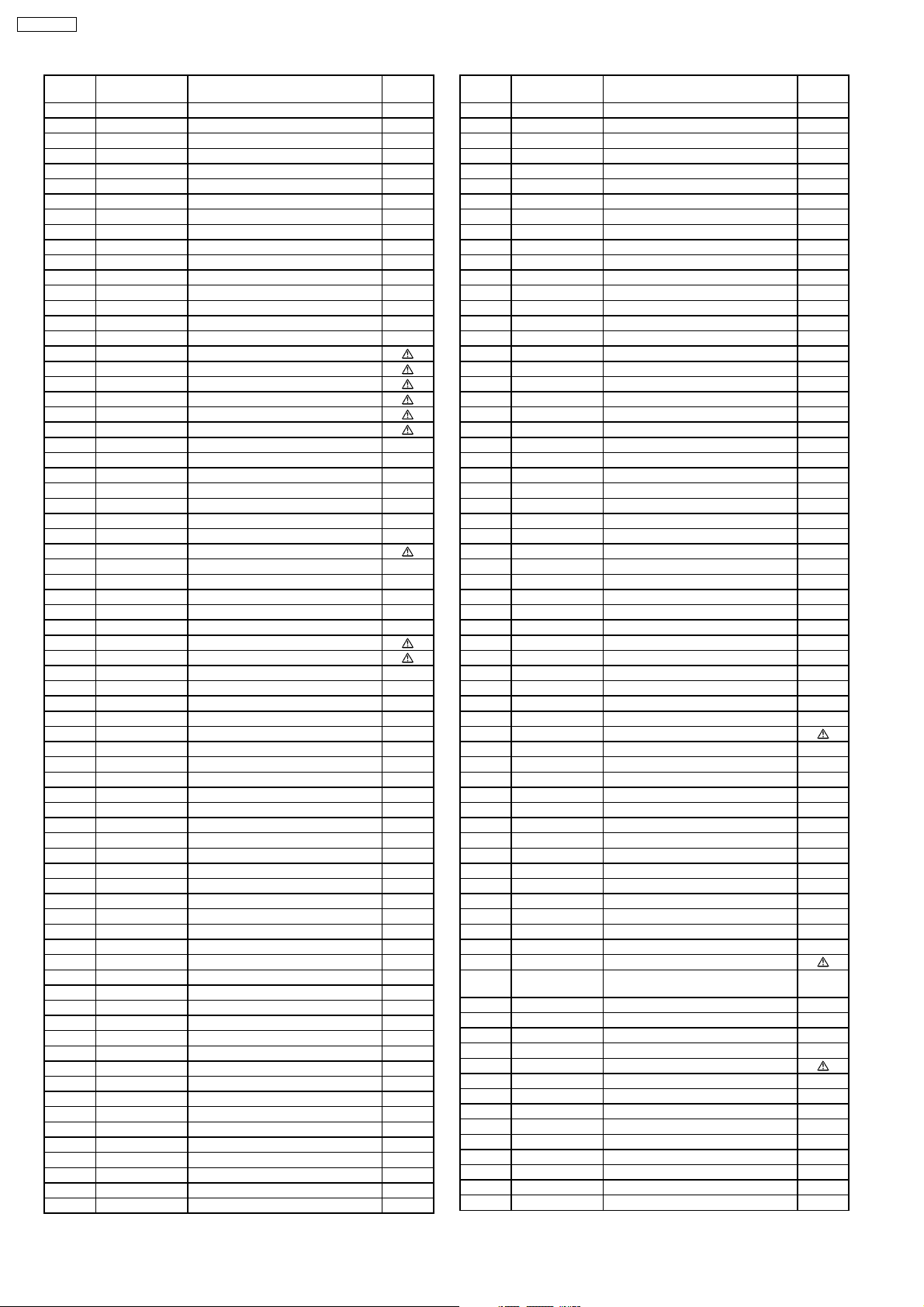
TX-21RX20T
Ref.
No.
C633 ECJ1VC1H471J C 470PF, J, 50V
C634 ECJ1VC1H471J C 470PF, J, 50V
C635 F2A1C101A310 E 330UF, 6.3V
C636 ECJ1VC1H471J C 470PF, J, 50V
C639 ECJ1VF1H104Z C 0.1UF, Z, 50V
C640 ECJ1VF1H104Z C 0.1UF, Z, 50V
C642 ECJ1VF1H104Z C 0.1UF, Z, 50V
C645 ECJ1VF1H104Z C 0.1UF, Z, 50V
C646 ECJ1VF1H104Z C 0.1UF, Z, 50V
C650 F2A1C331A339 E 330UF, 16V
C652 ECJ1VF1H104Z C 0.1UF, Z, 50V
C654 ECJ1VF1H104Z C 0.1UF, Z, 50V
C655 ECJ1VF1H104Z C 0.1UF, Z, 50V
C656 ECJ1VC1H270J C 27PF, J, 50V
C657 ECJ1VC1H560J C 56PF, J, 50V
C662 F2A0J101A317 E 100UF, 6.3V
C704 F1B2H471A058 C 470PF, 500V
C706 ECQM4222JZ P 2200PF, 400V
C811 F1A2E681A002 C 680PF, 250V
C812 F1A2E102A001 C 1000PF, 100V
C813 F1AAF472A009 C 4700PF, M
C815 F1AAF152A005 C 1500PF, M
C818 F2A1H1R0A317 C 1UF, 25V
C819 F0CAF224A066 P 0.22PF
C821 ECKW3D471KBP C 470PF, K, 2KV
C826 ECQV1H474JM P 0.47UF, J, 50V
C827 ECQB1H273JF P 0.027UF, J, 50V
C830 ECQB1H821KF P 820PF, J, 50V
C831 ECJ1VF1C105Z C 1UF, 16V
C840 F1A2E471A002 C 470PF, 250V
C841 ECKW3D151KBR C 150PF, K, 2KV
C842 F2A1H220A536 E 22UF, 50V
C843 F2A1E102A223 E 1000UF, 25V
C848 ECQB1H471JF P 470PF, J, 50V
C849 F1B2H152A072 C 1500F, 500V
C854 ECKWAE472ZED C 4700PF, Z,500V
C855 ECKWAE472ZED C 4700PF, Z,500V
C856 F2B2G221A086 C 220UF, Z, 400V
C857 F0C2G473A099 P 0.047UF,J, 400V
C859 ECKW3D821KBP C 820PF, K, 2KV
C863 F2A1C471A339 E 470UF, 16V
C865 ECKW3D331JBP C 330PF, J, 2KV
C867 F2A2C2210013 E 220UF, 160V
C869 F1J1E563A003 C 0.056UF, 25V
C870 F2A1C472A260 E 4700UF, 16V
C871 F1B2H471A058 C 470PF, 500V
C872 F2A1C222A232 E 2200UF, 16V
C873 F1B2H122A073 C 1200PF, 500V
C874 ECA1CM101B E 100UF, 16V
C875 F1J1H332A021 C 3300PF, 50V
C877 F2A1C1000079 E 10UF, 16V
C879 F2A0J331A260 E 330UF, 6.3V
C882 F2A1C101A310 E 330UF, 6.3V
C884 F2A1C332A232 E 33UF, 50V
C886 F2A1H330A342 E 1000UF, 16V
C887 F2A1C102A317 E 1000UF, 16V
C890 F1H1C104A143 C 0.1UF,K, 16V
C891 F2A1C101A310 E 330UF, 6.3V
C893 F2A1C221A338 E 22UF, 160V
C896 F0CAF224A066 P 0.22UF, 240V
C897 F1J1H103A590 C 0.01UF, 50V
C898 ECJ1VF1C105Z C 1UF, 16V
D1061 B3AGA0000126 DIODE (LED LIGHT)
D1132 B0BA3R800012 DIODE
D2103 B0AACJ000009 DIODE
D2107 B0AACJ000009 DIODE
D2108 B0AACJ000009 DIODE
D320 B0ACCK000005 DIODE
D321 B0ACCK000005 DIODE
D354 B0HAMP000067 DIODE
D355 B0HAMP000067 DIODE
D356 B0HAMP000067 DIODE
Part No. Part Name & Description Remarks
DIODES
Ref.
No.
D361 B0AACJ000009 DIODE
D362 B0AACJ000009 DIODE
D363 B0AACJ000009 DIODE
D364 B0AACJ000009 DIODE
D365 B0AACJ000009 DIODE
D366 B0AACJ000009 DIODE
D367 B0AACJ000009 DIODE
D368 B0AACK000004 DIODE
D402 B0HAJL000003 DIODE
D503 B0AACJ000009 DIODE
D504 B0AACJ000009 DIODE
D507 B0ACCK000005 DIODE
D511 MA4108J DIODE
D512 B0HAJL000003 DIODE
D513 B0HAMP000090 DIODE
D515 B0HAMP000090 DIODE
D520 B0ACQJ000001 DIODE
D552 B0HAMP000090 DIODE
D556 B0HAMV000027 DIODE
D557 B0HAMQ000001 DIODE
D558 MA185 DIODE
D601 B0ADDJ000025 DIODE
D610 MAZ80560HL DIODE
D670 MA2S72800L DIODE
D671 MA2S72800L DIODE
D683 MA2S72800L DIODE
D684 MA2S72800L DIODE
D702 B0ACCK000005 DIODE
D708 EU02 DIODE
D830 B0HAJL000001 DIODE
D831 B0BA03500016 DIODE
D832 B0BA3R300010 ZENER DIODE
D837 B0ACCK000012 DIODE
D846 B0BA8R000010 DIODE
D847 B0BA8R000010 DIODE
D848 B0HAQL000004 DIODE
D851 B0EAKT000018 DIODE
D852 B0HAJL000003 DIODE
D853 B0AACJ000009 DIODE
D854 B0AACJ000009 DIODE
D855 B0BA4R100013 DIODE
D860 B0EBNT000022 DIODE
D861 B0BA8R000010 DIODE
D862 MTZJ2.0B ZENER DIODE
D863 B0HAJL000003 DIODE
D865 B0BA3R500008 DIODE
D866 B0HAPV000009 DIODE
D867 B0JAME000058 DIODE
D872 B0JAPK000011 DIODE
D873 B0AACJ000009 DIODE
D876 B0AACJ000009 DIODE
D881 B0BA01500052 DIODE
D882 B0BA01500052 DIODE
D883 B0JAPK000013 DIODE
D884 B0AACJ000009 DIODE
D887 B0AACJ000009 DIODE
D896 D4EAC6210002 VARISTOR
IC1101 TVR4GAS772 EEPROM IC
IC2301 C0ZAZ0000220 IC
IC351 TDA6107AJFN1 IC
IC451 C1AA00000767 IC
IC601 TVR4G46-5 ROM IC
IC802 C0EAS0000024 IC
IC803 C5HABZZ00116 IC, HYBRID
IC851 C0DAEJG00001 IC, POWER SUPPLY
IC857 C0DBEHE00005 IC, POWER SUPPLY
IC871 C0DAZGG00012 IC, POWER SUPPLY
IC875 C0DBEHE00005 IC, POWER SUPPLY
L002 G0C100K00008 COIL
L003 G0C4R7JA0055 PEAKING COIL
Part No. Part Name & Description Remarks
INTEGRATED
CIRCUITS
COILS
46
Page 47
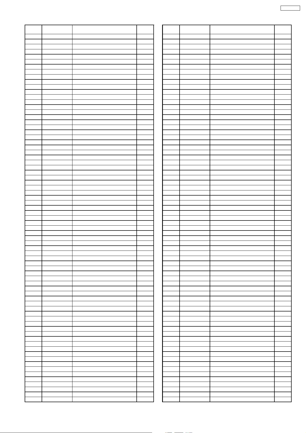
TX-21RX20T
Ref.
No.
L2302 J0JKA0000038 BEAD CORE
L2304 J0JKA0000038 BEAD CORE
L2306 J0JKA0000024 EMI FILTER
L2323 J0JKA0000038 BEAD CORE
L2324 J0JKA0000038 BEAD CORE
L3045 J0JCC0000411 BEAD CORE
L3046 J0JCC0000411 BEAD CORE
L3161 EXC3BB221H CHIP BEAD CORE
L3162 EXC3BB221H CHIP BEAD CORE
L3163 EXC3BB221H CHIP BEAD CORE
L3166 EXC3BB221H CHIP BEAD CORE
L376 J0JKA0000024 EMI FILTER
L501 J0JKA0000038 BEAD CORE
L505 J0JKA0000024 EMI FILTER
L514 J0JKA0000038 BEAD CORE
L515 J0JKA0000038 BEAD CORE
L517 J0JKA0000038 BEAD CORE
L518 J0JKA0000038 BEAD CORE
L550 J0JKB0000034 EMI FILTER
L554 ELC08D682E CHOKE COIL
L557 ELH5L7159 LINEARITY COIL
L565 EXCELSA39V BEAD CORE
L566 ELC18B471L CHOKE COIL
L601 G0C100K00008 COIL
L602 G0C100K00008 COIL
L603 G0C100K00008 COIL
L604 G0C100K00008 COIL
L605 TALV35VB8R2K PEAKING COIL
L606 G0C100K00008 COIL
L607 TALV35VB8R2K PEAKING COIL
L608 G0C3R9KA0030 PEAKING COIL
L610 J0JKB0000034 EMI FILTER
L611 G0C100K00008 COIL
L630 J0JCC0000411 BEAD CORE
L635 J0JCC0000411 BEAD CORE
L657 J0JCC0000411 BEAD CORE
L705 ELC18B103L CHOKE COIL
L819 ETQR36T020B CHOKE COIL
L842 J0JKA0000025 BEAD CORE
L845 J0JKA0000023 BEAD CORE
L865 J0JKA0000025 BEAD CORE
L866 J0JKA0000023 BEAD CORE
L867 J0JKB0000039 EMI FILTER
L894 G0A220GA0002 CHOKE COIL
Q1060 2SD0601A0L TRANSISTOR
Q1061 2SB709ATX TRANSISTOR
Q1062 2SD0601A0L TRANSISTOR
Q1063 2SD0601A0L TRANSISTOR
Q2101 2SB709ATX TRANSISTOR
Q304 2SB709ATX TRANSISTOR
Q305 2SB709ATX TRANSISTOR
Q306 2SB709ATX TRANSISTOR
Q320 2SD0601A0L TRANSISTOR
Q354 2SB709ATX TRANSISTOR
Q360 B1ACAA000019 TRANSISTOR
Q361 B1ACAA000019 TRANSISTOR
Q362 B1ACAA000019 TRANSISTOR
Q501 2SC4212H TRANSISTOR
Q520 2SB0792A0L TRANSISTOR
Q551 2SC6073000LK TRANSISTOR
Q603 2SD0601A0L TRANSISTOR
Q604 2SD0601A0L TRANSISTOR
Q605 2SD0601A0L TRANSISTOR
Q608 2SD0601A0L TRANSISTOR
Q610 2SB709ATX TRANSISTOR
Q701 B1DFDM000012 TRANSISTOR
Q702 2SD0601A0L TRANSISTOR
Q703 2SD0601A0L TRANSISTOR
Q846 2SD0601A0L TRANSISTOR
Q850 B1BCCM000002 TRANSISTOR
Q857 2SC54190QA TRANSISTOR
Q870 2SB709ATX TRANSISTOR
Part No. Part Name & Description Remarks
TRANSISTORS
Ref.
No.
R005 D0GB512JA008 F 5.1KOHM,J,1W
R006 ERJ3GEYJ473 M 47KOHM,J,1/16W
R007 ERJ3GEYJ682 M 6.8KOHM,J,1/16W
R008 ERJ3GEY0R00 M 0OHM,J,1/16W
R009 ERJ3GEY0R00 M 0OHM,J,1/16W
R1041 ERJ3EKF2321 M2.32KOHM,F,1/16W
R1043 ERJ3EKF2211 M2.21KOHM,F,1/16W
R1044 ERJ3EKF3241 M3.24KOHM,F,1/16W
R1045 ERJ3EKF5111 M5.11KOHM,F,1/16W
R1046 ERJ3EKF9091 M9.09KOHM,F,1/16W
R1047 ERJ3EKF1802 M 18KOHM,F,1/16W
R1061 ERJ3GEYJ361 F 360OHM,J,1/2W
R1062 ERDS2TJ102 C 1KOHM,J, 1/4W
R1063 ERJ3GEYJ752 M 7.5KOHM,J,1/16W
R1065 ERJ3GEYJ121 M 120OHM,J,1/16W
R1066 ERJ3GEYJ152 M 1.5KOHM,J,1/16W
R1067 ERJ3GEYJ470 M 47OHM,J,1/16W
R1068 ERJ3GEYJ103 M 10KOHM,J,1/16W
R1105 ERJ3GEYJ103 M 10KOHM,J,1/16W
R1106 ERJ3GEYJ102 M 1KOHM,J,1/16W
R1108 ERJ3GEYJ101 M 100OHM,J,1/16W
R1109 ERJ3GEYJ103 M 10KOHM,J,1/16W
R1112 ERJ3GEYJ102 M 1KOHM,J,1/16W
R1114 ERJ3GEYJ151 M 150OHM,J,1/16W
R1115 ERJ3GEYJ101 M 100OHM,J,1/16W
R1131 ERJ3GEYJ220 M 22OHM,J,1/16W
R1132 ERJ3GEYJ220 M 22OHM,J,1/16W
R1140 D1AC1002A094 M 10KOHM,F,1/16W
R1142 ERJ3EKF1001 M 1KOHM,F,1/16W
R1150 ERJ3GEYJ101 M 100OHM,J,1/16W
R1201 ERJ3GEYJ102 M 1KOHM,J,1/16W
R1202 ERJ3GEYJ102 M 1KOHM,J,1/16W
R1228 ERJ3GEYJ101 M 100OHM,J,1/16W
R1229 ERJ3GEYJ101 M 100OHM,J,1/16W
R2112 ERJ3GEYJ102 M 1KOHM,J,1/16W
R2114 ERJ3GEYJ104 M 100KOHM,J,1/16W
R2317 D0GB622JA008 F 6.2KOHM,J,1/2W
R2321 ERJ3GEYJ104 M 100KOHM,J,1/16W
R2322 ERJ3GEYJ104 M 100KOHM,J,1/16W
R253 D0GB751JA008 F 750OHM,J,1/2W
R255 D0GB751JA008 F 750OHM,J,1/2W
R256 ERDS2TJ272 C 2.7KOHM,J, 1/4W
R257 ERDS2TJ272 C 2.7KOHM,J, 1/4W
R3002 ERJ3GEYJ750 M 75OHM,J,1/16W
R3004 ERJ3GEYJ104 M 100KOHM,J,1/16W
R3008 ERJ3GEYJ104 M 100KOHM,J,1/16W
R3009 ERJ3GEYJ750 M 75OHM,J,1/16W
R3010 ERJ3GEYJ750 M 75OHM,J,1/16W
R3011 ERJ3GEYJ750 M 75OHM,J,1/16W
R3022 ERJ3GEYJ104 M 100KOHM,J,1/16W
R3024 ERJ3GEYJ104 M 100KOHM,J,1/16W
R3026 ERJ3GEYJ103 M 10KOHM,J,1/16W
R304 ERJ6GEYJ240 F 24OHM,J,1/4W
R305 ERJ6GEYJ240 F 24OHM,J,1/4W
R306 ERJ6GEYJ240 F 24OHM,J,1/4W
R307 ERJ3GEYJ121 M 120OHM,J,1/16W
R308 ERJ3GEYJ121 M 120OHM,J,1/16W
R309 ERJ3GEYJ121 M 120OHM,J,1/16W
R310 D0AE181JA046 C 180OHM,J, 1/4W
R3101 ERDS2TJ470 C 47OHM,J, 1/4W
R3102 ERDS2TJ470 C 47OHM,J, 1/4W
R3104 ERJ3GEY0R00 M 0OHM,J,1/16W
R3105 ERJ3GEY0R00 M 0OHM,J,1/16W
R311 D0AE181JA046 C 180OHM,J, 1/4W
R312 D0AE181JA046 C 180OHM,J, 1/4W
R3158 D0GB111JA008 F 110OHM,J,1/16W
R3159 D0GB111JA008 F 110OHM,J,1/16W
R3161 D0GB111JA008 F 110OHM,J,1/16W
R3162 D0GB111JA008 F 110OHM,J,1/16W
R3167 ERJ3GEYJ104 M 100KOHM,J,1/16W
R3168 ERJ3GEYJ104 M 100KOHM,J,1/16W
R3173 ERJ3GEY0R00 M 0OHM,J,1/16W
Part No. Part Name & Description Remarks
RESISTORS
47
Page 48
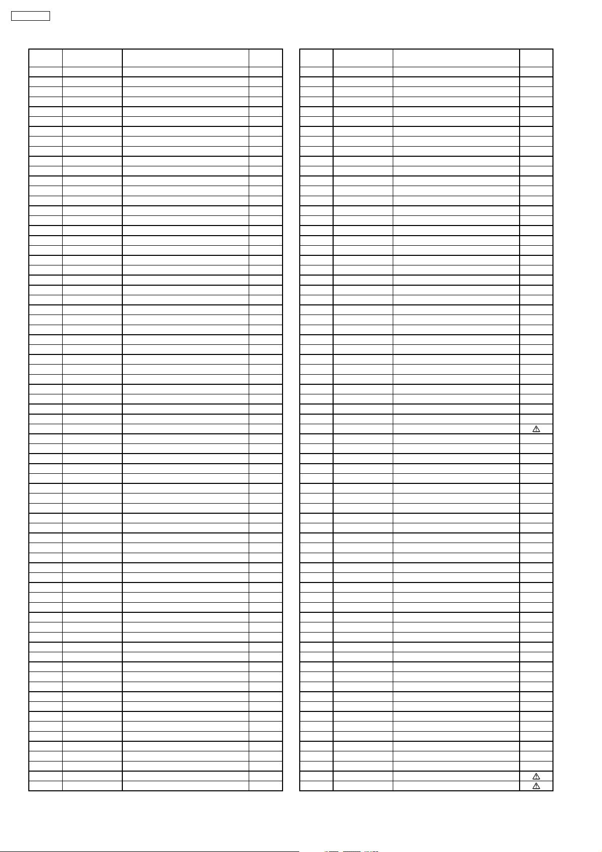
TX-21RX20T
Ref.
No.
R320 ERJ3GEYJ821 M 820OHM,J,1/16W
R321 D0AE220JA046 C 22OHM,J, 1/4W
R341 ERJ3GEYJ151 M 150OHM,J,1/16W
R342 ERJ3GEYJ151 M 150OHM,J,1/16W
R343 ERJ3GEYJ151 M 150OHM,J,1/16W
R351 ERJ3GEYJ331 M 330OHM,J,1/16W
R352 ERJ3GEYJ331 M 330OHM,J,1/16W
R353 ERJ3GEYJ331 M 330OHM,J,1/16W
R363 ERJ3GEYJ102 M 1KOHM,J,1/16W
R364 ERJ3GEYJ102 M 1KOHM,J,1/16W
R365 ERJ3GEYJ102 M 1KOHM,J,1/16W
R366 ERDS1TJ152 C 1.5KOHM,J, 1/2W
R367 ERDS1TJ152 C 1.5KOHM,J, 1/2W
R368 ERDS1TJ152 C 1.5KOHM,J, 1/2W
R372 ERQ12AJ121P F 120OHM,J,1/2W
R381 ERJ3GEYJ182 M 1.8KOHM,J,1/16W
R385 ERJ3GEY0R00 M 0OHM,J,1/16W
R401 ERDS2TJ104 C 100KOHM,J, 1/4W
R403 ERJ3GEYJ563 M 56KOHM,J,1/16W
R404 ERJ3GEYJ153 M 15KOHM,J,1/16W
R405 ERDS2TJ563 C 56KOHM,J, 1/4W
R406 ERDS1TJ1R5 C 1.5OHM,J, 1/2W
R407 ERG1SJ221E M 220OHM,J, 1W
R413 ERJ3GEYJ183 M 18KOHM,J,1/16W
R416 ERX2SJR56E M 0.56OHM,J, 2W
R451 ERJ3GEYJ223 M 22KOHM,J,1/16W
R453 ERJ3GEYJ101 M 100OHM,J,1/16W
R501 ERJ3GEYJ273 M 27KOHM,J,1/16W
R502 ERJ3GEYJ103 M 10KOHM,J,1/16W
R504 ERG2SJS332H M 10KOHM,J,1/10W
R507 ERDS2TJ561 C 560OHM,J, 1/4W
R508 ERG3FJ561H M 560OHM,J, 3W
R509 ERG3FJ561H M 560OHM,J, 3W
R511 ERJ3EKF1102 M 11KOHM,F,1/16W
R512 ERJ3EKF1152 M11.5KOHM, 1/10W
R513 ERQ14AJ100E F 10OHM,J, 1/4W
R518 D0DK3R3J0002 W 3.3OHM,J,1/10W
R522 ERDS2TJ363 C 36KOHM,J, 1/4W
R523 ERJ3GEYJ103 M 10KOHM,J,1/16W
R524 ERDS2TJ104 C 100KOHM,J, 1/4W
R525 ERJ3GEYJ392 M 3.9KOHM,J,1/16W
R551 ERG1FJ101P M 100OHM,J, 1W
R552 ERG1SJ102P M 1KOHM,J, 1W
R553 ERJ3GEYJ183 M 18KOHM,J,1/16W
R559 D0C12R2JA042 M 2.2OHM,J, 1W
R580 D0GB512JA008 F 5.1KOHM,J, 1W
R601 ERJ3GEYJ470 M 47OHM,J,1/16W
R602 ERDS2TJ103 C 10KOHM,J, 1/4W
R604 ERJ3GEYJ470 M 47OHM,J,1/16W
R605 ERJ3GEYJ470 M 47OHM,J,1/16W
R606 ERJ3GEYJ752 M 7.5KOHM,J,1/16W
R607 ERJ3GEYJ752 M 7.5KOHM,J,1/16W
R608 ERJ3GEYJ470 M 47OHM,J,1/16W
R609 ERJ3GEY0R00 M 0OHM,J,1/16W
R611 ERJ3GEYJ101 M 100OHM,J,1/16W
R612 ERJ3GEYJ392 M 3.9KOHM,J,1/16W
R614 ERJ3GEYJ221 M 220OHM,J,1/16W
R615 ERJ3GEYJ122 M 1.2KOHM,J,1/16W
R616 ERJ3GEYJ563 M 56KOHM,J,1/16W
R619 ERJ3GEYJ332 M 3.3KOHM,J,1/16W
R620 ERJ3EKF1002 M 10KOHM,F,1/16W
R621 ERJ3EKF2002 M 20KOHM,F,1/16W
R624 ERJ3GEYJ102 M 1KOHM,J,1/16W
R625 ERJ3GEYJ102 M 1KOHM,J,1/16W
R626 ERJ3GEYJ103 M 10KOHM,J,1/16W
R627 ERJ3GEYJ103 M 10KOHM,J,1/16W
R628 ERJ3GEYJ823 M 82KOHM,J,1/16W
R629 ERJ3GEY0R00 M 0OHM,J,1/16W
R632 ERJ3GEYJ682 M 6.8KOHM,J,1/16W
R634 ERJ3GEYJ151 M 150OHM,J,1/16W
R635 ERJ3GEYJ151 M 150OHM,J,1/16W
R636 ERJ3GEYJ101 M 100OHM,J,1/16W
R638 ERJ3GEY0R00 M 0OHM,J,1/16W
Part No. Part Name & Description Remarks
Ref.
No.
R640 ERJ3GEYJ471 M 470OHM,J,1/16W
R641 ERJ3GEY0R00 M 0OHM,J,1/16W
R643 ERJ3GEY0R00 M 0OHM,J,1/16W
R644 ERJ3GEYJ103 M 10KOHM,J,1/16W
R645 ERJ3GEYJ101 M 100OHM,J,1/16W
R646 ERJ3GEYJ183 M 18KOHM,J,1/16W
R647 ERJ3GEYJ750 M 75OHM,J,1/16W
R652 ERJ3GEYJ750 M 75OHM,J,1/16W
R653 ERJ3GEYJ750 M 75OHM,J,1/16W
R656 ERJ3GEYJ823 M 82KOHM,J,1/16W
R658 ERDS2TJ470 C 47OHM,J, 1/4W
R659 ERJ3GEYJ470 M 47OHM,J,1/16W
R660 ERJ3GEYJ470 M 47OHM,J,1/16W
R664 ERDS2T0T C 0OHM, 1/4W
R665 ERDS2T0T C 0OHM, 1/4W
R669 ERDS2T0T C 0OHM, 1/4W
R681 ERJ3GEYJ472 M 4.7KOHM,J,1/16W
R682 ERJ3GEYJ472 M 4.7KOHM,J,1/16W
R685 ERJ3GEYJ104 M 100KOHM,J,1/16W
R686 ERJ3GEYJ104 M 100KOHM,J,1/16W
R701 ERJ3GEYJ103 M 10KOHM,J,1/16W
R702 ERJ3GEYJ680 M 68OHM,J,1/16W
R703 ERJ3GEYJ472 M 4.7KOHM,J,1/16W
R704 ERJ3GEYJ471 M 470OHM,J,1/16W
R705 D0GB203JA008 F 20KOHM,J, 1W
R713 ERG3FJ100H M 10OHM,J, 3W
R715 ERDS2TJ472 C 4.7KOHM,J, 1/4W
R824 ERX12SJR27E M 0.27OHM,J, 1/2W
R825 ERJ3GEYJ471 M 470OHM,J,1/16W
R830 ERDS2TJ221 C 220OHM,J, 1/4W
R831 ERDS2TJ333 C 33KOHM,J, 1/4W
R832 ERJ3EKF4022 M 40.2KOHM,J,1/16W
R833 ERDS2TJ102 C 1KOHM,J, 1/4W
R834 ERG3FJ473H M 47KOHM,J, 3W
R836 ERG1SJ220P M 22OHM,J, 1W
R839 ERJ3GEYJ472 M 4.7KOHM,J,1/16W
R840 D0AW825JA001 C 8.2MOHM,J, 1W
R842 ERG2FJ150H M 15OHM,J, 2W
R847 ERDS2TJ473 C 47KOHM,J, 1/4W
R848 ERX12SJR22E M 0.22OHM,J, 1/2W
R850 ERG3SJS560H M 56OHM,J, 3W
R851 ERDS2TJ104 C 100KOHM,J, 1/4W
R852 D0AE162JA046 C 1.6KOHM,J, 1W
R854 ERG2FJ470H M 47OHM,J, 2W
R856 ERG2SJS104H M 100KOHM,J, 2W
R857 ERDS2TJ102 C 1KOHM,J, 1/4W
R858 ERX2SJ7R5E M 7.5OHM,J, 2W
R861 ERG1SJ390P M 39OHM,J, 1W
R862 ERDS2TJ182 C 1.8KOHM,J, 1/4W
R863 ERDS2TJ101 C 100OHM,J, 1/4W
R864 ERJ3GEYJ103 M 10KOHM,J,1/16W
R866 ERJ3GEYJ392 M 3.9KOHM,J,1/16W
R867 D0AE202JA046 C 2KOHM,J, 1/4W
R868 ERDS1TJ101 C 100OHM,J, 1/2W
R871 ERJ3GEYJ103 M 10KOHM,J,1/16W
R872 ERJ3EKF1052 F 10.5KOHM,J, 1/10W
R873 ERJ3EKF1802 M 18KOHM,F,1/16W
R875 ERJ3GEYJ822 M 8.2KOHM,J,1/16W
R876 ERJ3EKF1002 M 10KOHM,F,1/16W
R877 ERJ3EKF5101 F 27KOHM,J, 1W
R882 ERJ3GEYJ332 M 3.3KOHM,J,1/16W
R884 ERDS2TJ562 C 5.6KOHM,J, 1/4W
R885 ERJ3GEYJ752 M 7.5KOHM,J,1/16W
R886 D0GB433JA008 F 43KOHM,J, 1W
R888 ERJ3GEYJ103 M 10KOHM,J,1/16W
R889 ERX3FJ8R2H M 8.2OHM,J, 3W
R890 ERG1SJ273P M 27KOHM,J, 1W
R894 ERJ3EKF1303 M 130KOHM, 1/10W
R896 ERC12ZGK225D S 2.2MOHM,K, 1/2W
T553 ETH19Y210BZ H DRIVE TRANS
T554 BSC27-0102K FLYBACK TRANS
Part No. Part Name & Description Remarks
TRANSFORMERS
48
Page 49
TX-21RX20T
Ref.
No.
T801 ETS35AH1P6AC SWITCHING TRANS
A1 K1KA05AA0180 CONNECTOR
A13 K1KA07AA0190 CONNECTOR
A19 K1KA06AA0180 CONNECTOR
A2 K1KA06AA0659 CONNECTOR
A25 K1KA02A00676 CONNECTOR
A27 K1KA02A00720 CONNECTOR
A4 K1KA04AA0190 CONNECTOR
A5 K1KA04AA0190 CONNECTOR
A8 K1KA04AA0093 CONNECTOR
CF835 TAP4GA0005 POSISTOR
F860 K5D502BL0009 FUSE
G13 K1KA07BA0055 CONNECTOR
G19 K1KA06BA0055 CONNECTOR
G20 K1KA02BA0055 CONNECTOR
JA10 ERJ6GEY0R00 M 0OHM,J,1/10W
JA11 ERJ6GEY0R00 M 0OHM,J,1/10W
JA12 ERJ6GEY0R00 M 0OHM,J,1/10W
JA13 ERJ6GEY0R00 M 0OHM,J,1/10W
JA16 ERJ6GEY0R00 M 0OHM,J,1/10W
JA17 ERJ6GEY0R00 M 0OHM,J,1/10W
JA2 ERJ6GEY0R00 M 0OHM,J,1/10W
JA29 ERJ6GEY0R00 M 0OHM,J,1/10W
JA30 ERJ6GEY0R00 M 0OHM,J,1/10W
JA31 ERJ6GEY0R00 M 0OHM,J,1/10W
JA32 ERJ6GEY0R00 M 0OHM,J,1/10W
JA33 ERJ6GEY0R00 M 0OHM,J,1/10W
JA35 ERJ6GEY0R00 M 0OHM,J,1/10W
JA36 ERJ6GEY0R00 M 0OHM,J,1/10W
JA4 ERJ6GEY0R00 M 0OHM,J,1/10W
JA45 ERJ6GEY0R00 M 0OHM,J,1/10W
JA5 ERJ6GEY0R00 M 0OHM,J,1/10W
JA6 ERJ6GEY0R00 M 0OHM,J,1/10W
JA7 ERJ6GEY0R00 M 0OHM,J,1/10W
JA8 ERJ6GEY0R00 M 0OHM,J,1/10W
JA9 ERJ6GEY0R00 M 0OHM,J,1/10W
JK3002 K4BK10B00005 AV TERMINAL
JK3003 K4BK10B00006 AV TERMINAL
JK3202 K4BC07B00007 AV TERMINAL
JK3203 K4BC07B00006 AV TERMINAL
JS110 ERJ3GEY0R00 M 0OHM,J,1/16W
JS2315 ERJ3GEY0R00 M 0OHM,J,1/16W
JS2341 ERJ3GEY0R00 M 0OHM,J,1/16W
JS2342 ERJ3GEY0R00 M 0OHM,J,1/16W
JS3043 ERJ3GEY0R00 M 0OHM,J,1/16W
JS3044 ERJ3GEY0R00 M 0OHM,J,1/16W
JS3131 ERJ3GEY0R00 M 0OHM,J,1/16W
JS3132 ERJ3GEY0R00 M 0OHM,J,1/16W
JS631 ERJ3GEY0R00 M 0OHM,J,1/16W
JS632 ERJ3GEY0R00 M 0OHM,J,1/16W
JS633 ERJ3GEY0R00 M 0OHM,J,1/16W
JS634 ERJ3GEY0R00 M 0OHM,J,1/16W
JS670 ERJ3GEY0R00 M 0OHM,J,1/16W
JS807 ERJ6GEY0R00 M 0OHM,J,1/10W
JS850 ERJ3GEY0R00 M 0OHM,J,1/16W
JS878 ERJ3GEY0R00 M 0OHM,J,1/16W
JS879 ERJ3GEY0R00 M 0OHM,J,1/16W
JS883 ERJ3GEY0R00 M 0OHM,J,1/16W
JSG3165 ERJ3GEY0R00 M 0OHM,J,1/16W
JSG3167 ERJ3GEY0R00 M 0OHM,J,1/16W
K20 K1KA02BA0055 CONNECTOR
L2 K1KA06AA0659 CONNECTOR
L3 K1KA04AA0190 CONNECTOR
LF891 ELF21V012S LINE FILTER
P14 K1KA02A00676 CONNECTOR
PC860 B3PAA0000363 PHOTO COUPLER
RM1062 B3RAD0000160 REMOCON RECEIVER
SC352 K3B09CA00014 CRT SOCKET
SW1021 EVQ11G05R SWITCH
SW1022 EVQ11G05R SWITCH
SW1023 EVQ11G05R SWITCH
SW1024 EVQ11G05R SWITCH
Part No. Part Name & Description Remarks
OTHERS
Ref.
No.
SW1025 EVQ11G05R SWITCH
SW1026 EVQ11G05R SWITCH
SW15 K1KA02A00676 CONNECTOR
SW5 K1KA02A00720 CONNECTOR
SW841 ESB92DA1B SWITCH
RL831 K6B1CDA00028 RELAY
TU001 ENV59K30G3RF TUNER
V1 K1KA05BA0055 CONNECTOR
X601 H0D202500007 CRYSTAL OSC
XF101 J0C3525A0005 SAW FILTER
Part No. Part Name & Description Remarks
49
 Loading...