

Panasonic TH-80LFB70 operating instructions
Operating Instructions
Display Operations
Touch Screen LCD Display (for business use)
Model No.
TH-80LFB70U
TH-80LFB70E
TH-80LFB70W
English
Please read these instructions before operating your set
and retain them for future reference.

Dear Panasonic Customer
Welcome to the Panasonic family of customers. We hope that you will have many years of
enjoyment from your new LCD Display.
To obtain maximum benefit from your set, please read these Instructions before making
any adjustments, and retain them for future reference.
Retain your purchase receipt also, and note down the model number and serial number of
your set in the space provided on the rear cover of these instructions.
Visit our Panasonic Web Site http://panasonic.net
Table of Contents
Important Safety Instructions .................................. 1
FCC STATEMENT ...................................................... 2
Important Safety Notice ........................................... 3
Safety Precautions ................................................... 4
Accessories .............................................................. 8
Accessories Supply ................................................. 8
Contents in the CD-ROM ........................................ 8
Remote Control Batteries ........................................ 9
Mounting Pen Stand ................................................ 9
Connections ............................................................ 10
AC cord connection and xing, cable xing ........... 10
Speaker connection ................................................11
Video equipment connection ..................................11
VIDEO and COMPONENT / RGB IN connection
HDMI connection ................................................... 12
DVI-D IN connection .............................................. 13
PC Input Terminals connection .............................. 14
SERIAL Terminals connection ............................... 15
PC OUT connection............................................... 16
Example connection using the DIGITAL LINK
Terminal ................................................................. 17
Power On / Off ......................................................... 18
Selecting the input signal ...................................... 20
Basic Controls ........................................................ 21
ASPECT Controls ................................................... 23
Digital Zoom ............................................................ 24
MULTI PIP ................................................................ 25
Multi-touch Operation ............................................ 26
Touch Zoom ............................................................ 29
Memory Viewer Function ....................................... 30
Using Built-in WhiteBoard ..................................... 37
Using WhiteBoard Software .................................. 44
Using Miracast(TM) ................................................ 45
On-Screen Menu Displays ..................................... 46
Adjusting Pos./Size ................................................ 48
Picture Adjustments ............................................... 51
Advanced settings ................................................. 52
.... 12
Picture Pro les ....................................................... 53
Saving pro les ....................................................... 54
Loading pro les ..................................................... 55
Editing pro les ....................................................... 55
Sound Adjustment .................................................. 56
SDI Sound Output ................................................. 56
Setup menu ............................................................. 57
Day/Time Settings / On/Off Timer Settings .......... 58
Day/Time Settings ................................................. 58
On/Off Timer Settings ............................................ 58
Touch Screen Settings ........................................... 59
MULTI PIP Settings ................................................. 60
Screensaver (For preventing image retention) .... 61
Setup of Screensaver Time ................................... 62
ECO Mode settings ................................................. 63
Customizing the Input labels ................................. 64
Function Button Settings ....................................... 65
Memory Viewer Settings ........................................ 66
Monitor Out ............................................................. 66
No activity power off .............................................. 67
Menu Display Duration / OSD Brightness ............ 67
OSD Language ........................................................ 67
Setup for Input Signals .......................................... 68
Component / RGB-in select ................................... 68
YUV / RGB-in select .............................................. 68
Signal menu .......................................................... 69
Options Adjustments ............................................. 72
Weekly Command Timer ....................................... 75
Audio input select .................................................. 77
Input Search .......................................................... 78
RS-232C/LAN Information Timing ......................... 79
Troubleshooting ..................................................... 80
When using Miracast ............................................. 82
List of Aspect Modes ............................................. 83
Applicable Input Signals ........................................ 85
Shipping condition ................................................. 86
Command list of Weekly Command Timer ........... 87
Speci cations ......................................................... 88
Software License .................................................... 89
Note:
Image retention may occur. If you display a still picture for an extended period, the image might remain on the screen.
However, it will disappear after a while.
ii
CAUTION
RISK OF ELECTRIC SHOCK
DO NOT OPEN
WARNING: To reduce the risk of electric shock, do not remove cover or back.
No user-serviceable parts inside. Refer servicing to quali ed service personnel.
The lightning flash with
arrow-head within a triangle
is in tend ed to tell the user
that parts inside the product
are a risk of electric shock
to per sons.
WARNING : To prevent damage which may result in re or shock hazard, do not expose this apparatus to
rain or mois ture.
Do not place containers with water ( ower vase, cups, cosmetics, etc.) above the set.
(including on shelves above, etc.)
WARNING : 1) To prevent electric shock, do not remove cover. No user serviceable parts inside. Refer servicing
to quali ed service personnel.
2) Do not remove the grounding pin on the power plug. This apparatus is equipped with a three pin
grounding-type power plug. This plug will only t a grounding-type power outlet. This is a safety
fea ture. If you are unable to insert the plug into the outlet, contact an electrician.
Do not defeat the purpose of the grounding plug.
The exclamation point within
a triangle is intended to
tell the user that important
operating and servicing
instructions are in the papers
with the ap pli ance.
Important Safety Instructions
1) Read these instructions.
2) Keep these instructions.
3) Heed all warnings.
4) Follow all instructions.
5) Do not use this apparatus near water.
6) Clean only with dry cloth.
7) Do not block any ventilation openings. Install in accordance with the manufacturer’s instructions.
8) Do not install near any heat sources such as radiators, heat registers, stoves, or other apparatus (including
ampli ers) that produce heat.
9) Do not defeat the safety purpose of the polarized or grounding-type plug. A polarized plug has two blades with
one wider than the other. A grounding type plug has two blades and a third grounding prong. The wide blade
or the third prong are provided for your safety. If the provided plug does not t into your outlet, consult an
electrician for replacement of the obsolete outlet.
10) Protect the power cord from being walked on or pinched particularly at plugs, convenience receptacles, and
the point where they exit from the apparatus.
11) Only use attachments / accessories speci ed by the manufacturer.
12) Use only with the cart, stand, tripod, bracket, or table speci ed by the manufacturer, or sold
with the apparatus. When a cart is used, use caution when moving the cart / apparatus
combination to avoid injury from tip-over.
13) Unplug this apparatus during lightning storms or when unused for long periods of time.
14) Refer all servicing to quali ed service personnel. Servicing is required when the apparatus has been damaged
in any way, such as power-supply cord or plug is damaged, liquid has been spilled or objects have fallen into
the apparatus, the apparatus has been exposed to rain or moisture, does not operate normally, or has been
dropped.
15) To prevent electric shock, ensure the grounding pin on the AC cord power plug is securely connected.
1
FCC STATEMENT
This equipment has been tested and found to comply with the limits for a Class B digital device, pursuant to Part
15 of the FCC Rules. These limits are designed to provide reasonable protection against harmful interference
in a residential installation. This equipment generates, uses and can radiate radio frequency energy and, if not
installed and used in accordance with the instructions, may cause harmful interference to radio communications.
However, there is no guarantee that interference will not occur in a particular installation. If this equipment does
cause harmful interference to radio or television reception, which can be determined by turning the equipment
off and on, the user is encouraged to try to correct the interference by one or more of the following measures:
• Reorient or relocate the receiving antenna.
• Increase the separation between the equipment and receiver.
• Connect the equipment into an outlet on a circuit different from that to which the receiver is connected.
• Consult the dealer or an experienced technician for help.
This device complies with Part15 of the FCC Rules. Operation is subject to the following two conditions: (1) This
device may not cause harmful interference, and (2) this device must accept any interference received, including
interference that may cause undesired operation.
FCC CAUTION:
To assure continued compliance, follow the attached installation instructions and use only shielded
interface cables when connecting to computer or peripheral devices. Some recommended user provided
interface cables may require usage of the attached ferrite core kit(s), refer to interface cable connection
instructions for details. Any changes or modi cations not expressly approved by Panasonic Corp. of
North America could void the user’s authority to operate this device.
FCC Declaration of Conformity
Model No. TH-80LFB70U
Responsible Party: Panasonic Corporation of North America
Two Riverfront Plaza, Newark, New Jersey 07102-5490
Contact Source: Panasonic System Communications Company of North America
1-877-655-2357
CANADIAN NOTICE:
This Class B digital apparatus complies with Canadian ICES-003.
Note:
Image retention may occur. If you display a still picture for an extended period, the image might remain on the
screen. However, it will disappear after a while.
Trademark Credits
• VGA is a trademark of International Business Machines Corporation.
• Microsoft
Microsoft Corporation in the United States and/or other countries.
• Macintosh, Mac, Mac OS, OS X and Safari are the trademarks of Apple Inc. registered in the United States and
other countries.
• SVGA, XGA, SXGA and UXGA are registered trademarks of the Video Electronics Standard Association.
Even if no special notation has been made of company or product trademarks, these trademarks have been
fully respected.
• HDMI, the HDMI Logo, and High-De nition Multimedia Interface are trademarks or registered trademarks of
HDMI Licensing LLC in the United States and other countries.
• RoomView, Crestron RoomView and Fusion RV are registered trademarks of Crestron Electronics, Inc, and
Crestron Connected is the trademark of Crestron Electronics, Inc.
• Miracast is a trademark of Wi-Fi Alliance.
• Android is a registered trademark of Google Inc.
• iPad, iPhone, and iPod touch are trademarks of Apple Inc., registered in the U.S. and other countries.
®
, Windows®, Windows Vista®, and Internet Explorer® are the registered trademarks or trademarks of
2
Important Safety Notice
IMPORTANT: THE MOULDED PLUG
WARNING
1) To prevent damage which may result in re or shock hazard, do not expose this appliance to dripping
or splashing.
Do not place containers with water ( ower vase, cups, cosmetics, etc.) above the set. (including on
shelves above, etc.)
No naked ame sources, such as lighted candles, should be placed on / above the set.
2) To prevent electric shock, do not remove cover. No user serviceable parts inside. Refer servicing to quali ed
service personnel.
3) Do not remove the earthing pin on the power plug. This apparatus is equipped with a three pin earthing-type
power plug. This plug will only t an earthing-type power outlet. This is a safety feature. If you are unable to
insert the plug into the outlet, contact an electrician.
Do not defeat the purpose of the earthing plug.
4) To prevent electric shock, ensure the earthing pin on the AC cord power plug is securely connected.
CAUTION
This appliance is intended for use in environments which are relatively free of electromagnetic elds.
Using this appliance near sources of strong electromagnetic elds or where electrical noise may overlap with the
input signals could cause the picture and sound to wobble or cause interference such as noise to appear.
To avoid the possibility of harm to this appliance, keep it away from sources of strong electromagnetic elds.
IMPORTANT INFORMATION
If a display is not positioned in a suf ciently stable location, it can be potentially hazardous due to falling. Many
injuries, particularly to children, can be avoided by taking simple precautions such as:
• Using cabinets or stands recommended by the manufacturer of the display.
• Only using furniture that can safely support the display.
• Ensuring the display is not overhanging the edge of the supporting furniture.
• Not placing the display on tall furniture (for example, cupboards or bookcases) without anchoring both the furniture
and the display to a suitable support.
• Not standing the displays on cloth or other materials placed between the display and supporting furniture.
• Educating children about the dangers of climbing on furniture to reach the display or its controls.
FOR YOUR SAFETY, PLEASE READ THE FOLLOWING TEXT CAREFULLY.
This display is supplied with a moulded three pin mains plug for your safety and convenience. A 10 amp fuse is
tted in this plug. Shall the fuse need to be replaced, please ensure that the replacement fuse has a rating of 10
amps and that it is approved by ASTA or BSI to BS1362.
Check for the ASTA mark
If the plug contains a removable fuse cover, you must ensure that it is re tted when the fuse is replaced.
If you lose the fuse cover the plug must not be used until a replacement cover is obtained.
A replacement fuse cover can be purchased from your local Panasonic dealer.
Do not cut off the mains plug.
Do not use any other type of mains lead except the one supplied with this display.
The supplied mains lead and moulded plug are designed to be used with this display to avoid
interference and for your safety.
If the socket outlet in your home is not suitable, get it changed by a quali ed electrician.
If the plug or mains lead becomes damaged, purchase a replacement from an authorized dealer.
IMPORTANT: THE MOULDED PLUG
or the BSI mark on the body of the fuse.
ASA
WARNING : — THIS DISPLAY MUST BE EARTHED.
How to replace the fuse.
Open the fuse compartment with a screwdriver and replace the fuse.
3

Safety Precautions
WARNING
Setup
This LCD Display is for use only with the following optional accessories. Use with any other type of optional
accessories may cause instability which could result in the possibility of injury.
(All of the following accessories are manufactured by Panasonic Corporation.)
• Pedestal .................................................................................... TY-ST65P20
• Mobile stand for Display ............................................................ TY-ST80LF70
• Wall-hanging bracket (vertical) .................................................. TY-WK70PV50
• BNC Dual Video Terminal Board ............................................... TY-FB9BD
• HD-SDI Terminal Board ............................................................. TY-FB9HD
• HD-SDI Terminal Board with audio ........................................... TY-FB10HD
• Dual Link HD-SDI Terminal Board ............................................. TY-FB11DHD
• Dual HDMI Terminal Board ....................................................... TY-FB10HMD
• DVI-D Terminal Board ............................................................... TY-FB11DD
• Digital Interface Box .................................................................. ET-YFB100G
Always be sure to ask a quali ed technician to carry out set-up.
Small parts can present choking hazard if accidentally swallowed. Keep small parts away from young children. Discard
unneeded small parts and other objects, including packaging materials and plastic bags/sheets to prevent them from
being played with by young children, creating the potential risk of suffocation.
Do not place the Display on sloped or unstable surfaces, and ensure that the Display does not hang over the
edge of the base.
• The Display may fall off or tip over.
Do not place any objects on top of the Display.
• If water is spills onto the Display or foreign objects get inside it, a short-circuit may occur which could result in re
or electric shock. If any foreign objects get inside the Display, please consult your local Panasonic dealer.
Transport only in upright position!
• Transporting the unit with its display panel facing upright or downward may cause damage to the internal
circuitry.
Ventilation should not be impeded by covering the ventilation openings with items such as newspapers, table
cloths and curtains.
For suf cient ventilation;
Leave a space of 3
keep the space between the bottom of the display and the oor surface.
Cautions for Wall Installation
• Wall installation should be performed by an installation professional. Installing the Display incorrectly may lead to
an accident that results in death or serious injury. Use the speci ed accessories.
• If you terminate the use of the Display on the wall, ask a professional to remove the Display as soon as possible.
Do not install the product to a place where the product is exposed to direct sunlight.
• If the screen is exposed to direct sunlight, the liquid crystal panel may have adverse effect.
15/16” (10 cm) or more at the top, left and right, and 2 3/4” (7 cm) or more at the rear, and also
4

Safety Precautions
When using the LCD Display
The Display is designed to operate on 110 - 127 or 220 - 240 V AC, 50/60 Hz.
Do not cover the ventilation holes.
• Doing so may cause the Display to overheat, which can cause re or damage to the Display.
Do not stick any foreign objects into the Display.
• Do not insert any metal or ammable objects into the ventilations holes or drop them onto the Display, as doing so
can cause re or electric shock.
Do not remove the cover or modify it in any way.
• High voltages which can cause severe electric shocks are present inside the Display. For any inspection, adjustment
and repair work, please contact your local Panasonic dealer.
Ensure that the mains plug is easily accessible.
An apparatus with CLASS I construction shall be connected to a mains socket outlet with a protective earthing
connection.
Do not use any power supply cord other than that provided with this unit.
• Doing so may cause re or electric shocks.
Securely insert the power supply plug as far as it will go.
• If the plug is not fully inserted, heat may be generated which could cause re. If the plug is damaged or the wall
socket is loose, they shall not be used.
Do not handle the power supply plug with wet hands.
• Doing so may cause electric shocks.
Do not do anything that may damage the power cable. When disconnecting the power cable, pull on the plug
body, not the cable.
• Do not damage the cable, make any modi cations to it, place heavy objects on top of it, heat it, place it near any
hot objects, twist it, bend it excessively or pull it. To do so may cause re and electric shock. If the power cable is
damaged, have it repaired at your local Panasonic dealer.
Do not remove covers and NEVER modify the Display yourself
• Do not remove the rear cover as live parts are accessible when it is removed. There are no user serviceable parts
inside. (High-voltage components may cause serious electrical shock.)
• Have the Display checked, adjusted, or repaired at your local Panasonic dealer.
Keep the Pen Stand xing screw and washer out of reach of children to prevent swallowing.
If the Display is not going to be used for any prolonged length of time, unplug the power supply plug from
the wall outlet.
To prevent the spread of re, keep candles or other open ames away from this product at all times.
If problems occur during use
If a problem occurs (such as no picture or no sound), or if smoke or an abnormal odour starts to come out
from the Display, immediately unplug the power supply plug from the wall outlet.
• If you continue to use the Display in this condition, re or electric shock could result. After checking that the smoke
has stopped, contact your local Panasonic dealer so that the necessary repairs can be made. Repairing the Display
yourself is extremely dangerous, and shall never be done.
If water or foreign objects get inside the Display, if the Display is dropped, or if the cabinet becomes damages,
disconnect the power supply plug immediately.
• A short circuit may occur, which could cause re. Contact your local Panasonic dealer for any repairs that need to
be made.
5

Safety Precautions
CAUTION
When using the LCD Display
Do not bring your hands, face or objects close to the ventilation holes of the Display.
• Heated air comes out from the ventilation holes at the top of Display will be hot. Do not bring your hands or face,
or objects which cannot withstand heat, close to this port, otherwise burns or deformation could result.
Be sure to disconnect all cables before moving the Display.
• If the Display is moved while some of the cables are still connected, the cables may become damaged, and re or
electric shock could result.
Disconnect the power supply plug from the wall socket as a safety precaution before carrying out any
cleaning.
• Electric shocks can result if this is not done.
Clean the power cable regularly to prevent it becoming dusty.
• If dust built up on the power cord plug, the resultant humidity can damage the insulation, which could result in re.
Pull the power cord plug out from the wall outlet and wipe the mains lead with a dry cloth.
Do not burn or breakup batteries.
• Batteries must not be exposed to excessive heat such as sunshine, re or the like.
Cleaning and maintenance
The front of the display panel has been specially treated. Wipe the panel surface gently using only a cleaning
cloth or a soft, lint-free cloth.
• If the surface is particularly dirty, wipe with a soft, lint-free cloth which has been soaked in pure water or water in
which neutral detergent has been diluted 100 times, and then wipe it evenly with a dry cloth of the same type until
the surface is dry.
• Do not scratch or hit the surface of the panel with ngernails or other hard objects, otherwise the surface may
become damaged. Furthermore, avoid contact with volatile substances such as insect sprays, solvents and thinner,
otherwise the quality of the surface may be adversely affected.
If the cabinet becomes dirty, wipe it with a soft, dry cloth.
• If the cabinet is particularly dirty, soak the cloth in water to which a small amount of neutral detergent has been
added and then wring the cloth dry. Use this cloth to wipe the cabinet, and then wipe it dry with a dry cloth.
• Do not allow any detergent to come into direct contact with the surface of the Display. If water droplets get inside
the unit, operating problems may result.
• Avoid contact with volatile substances such as insect sprays, solvents and thinner, otherwise the quality of the
cabinet surface may be adversely affected or the coating may peel off. Furthermore, do not leave it for long periods
in contact with articles made from rubber or PVC.
Wipe off dirt on the IR transmission part with soft cloth.
• Wipe off dirt on the IR transmission part with soft cloth once a day.
If malfunction is due to dirt on the IR transmission part, simply wiping it off lightly can recover the performance.
If dirt is sticky, wipe it off with cloth wrung out of neutral detergent diluted with water and then wipe the part with
dry cloth.
Usage of a chemical cloth
• Do not use a chemical cloth for the panel surface.
• Follow the instructions for the chemical cloth to use it for the cabinet.
Ask your dealer to clean the inside at least once a year.
• Dust accumulated inside may interfere with the infrared beam for touch detection, resulting in poor performance.
Ask your dealer to clean the inside at least once a year.
6

Safety Precautions
Touch panel
Carefully observe the following instructions as the display has an optical touch panel.
Do not expose the display to direct sunlight or strong light source during use.
• Otherwise malfunction may occur since the optical touch panel of the display uses infrared rays.
After turning on the power of the display, do not touch the IR transmission part
and the screen until any image is displayed.
• Otherwise the touched part may be detected as defective elements, resulting in
abnormal operation. If this occurred, turn the display off and then on.
Always use a nger or the supplied pen to operate the touch panel. Do not use a hard or sharp tip such as
nail, ball-point pen, and pencil.
When using any other infrared device, keep a distance to prevent erroneous operation.
IR transmission part
7
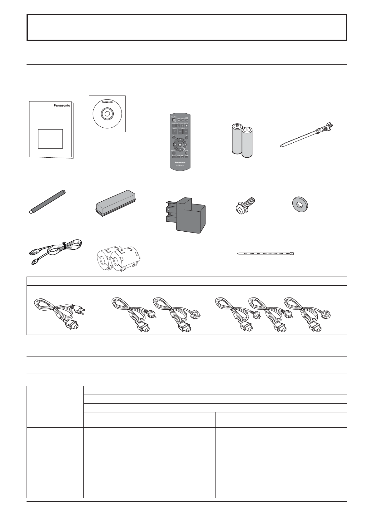
Accessories
Accessories Supply
Check that you have the accessories and items shown
Operating
Instruction book
Pen × 4
USB cable × 1
Software CD-ROM × 1
Eraser × 1 Pen Stand × 1
Ferrite core × 2
J0KG00000014
Remote Control
Transmitter
N2QAYB000691
(see page 9)
Use the Ferrite cores
to comply with the EMC
standard. (see page 13)
Batteries for the Remote
Control Transmitter
(R6 (UM3) Size × 2)
Screw × 2
(see page 9)
Cable tie × 2
TMM17499
Clamper × 1
TMME289
Washer × 2
(see page 9)
Power supply cord
TH-80LFB70U TH-80LFB70E TH-80LFB70W
Attention
Store small parts in an appropriate manner, and keep them away from young children.
Contents in the CD-ROM
The contents below are included in the supplied CD-ROM.
Instruction
(PDF)
Software
Operating Instructions - Display Operations
Operating Instructions - Network Operations
Operating Instructions - Wireless Manager ME
Software license GNU GENERAL PUBLIC LICENSE
GNU LESSER GENERAL PUBLIC LICENSE
WhiteBoard Software (Windows) Allows the display to be used as whiteboard.
You can run the software directly from external
storage without installing it in your computer.
(see page 44)
Wireless Manager ME (Windows/Mac) Allows the image on the computer screen to be
sent wirelessly or via wired LAN.
Switch the input to Panasonic APPLICATION
before use. For more details, see the instruction
manual of Wireless Manager ME.
8

Accessories
Remote Control Batteries
Requires two R6 batteries.
1. Pull and hold the hook, then open
the battery cover.
2. Insert batteries - note correct
polarity (+ and -).
“R6 (UM3)” size
-
+
+
-
Helpful Hint:
For frequent remote control users, replace old batteries with Alkaline
batteries for longer life.
Precaution on battery use
Incorrect installation can cause battery leakage and corrosion that will damage the remote control transmitter.
Disposal of batteries should be in an environment-friendly manner.
Observe the following precaution:
1. Batteries shall always be replaced as a pair. Always use new batteries when replacing the old set.
2. Do not combine a used battery with a new one.
3. Do not mix battery types (example: “Zinc Carbon” with “Alkaline”).
4. Do not attempt to charge, short-circuit, disassemble, heat or burn used batteries.
5.
Battery replacement is necessary when remote control acts sporadically or stops operating the Display set.
6. Do not burn or breakup batteries.
7. Batteries must not be exposed to excessive heat such as sunshine, re or the like.
3. Replace the cover.
Mounting Pen Stand
The supplied Pen Stand can be mounted on one of the nine positions on the back of the Display.
1 Remove a screw from the back cover.
2 Peel the paper backing off the supplied washer.
3 Paste the washer to a screw hole for the pen stand.
Any of the hole A to D can be used to x the pen stand.
A
B
C
Pen Stand
(supplied)
Washer (supplied)
D
4 Mount the Pen Stand with the supplied screw.
Screw
(supplied)
Pen Stand
The Pen Stand can hold four pens and one Eraser.
9
Connections
AC cord connection and xing, cable xing
AC cord xing
Unplug the AC cord
Unplug the AC cord pressing the
Plug the AC cord into the display unit.
Plug the AC cord until it clicks.
Note:
Make sure that the AC cord is locked on
both the left and right sides.
Using the clamper
Secure any excess cables with clamper as required.
Note:
One clamper is supplied with this unit. In case of securing cables at four positions, please purchase it separately.
If you need more clampers, purchase them from your dealer. (Available from the customer service)
two knobs.
Note:
When disconnecting the AC cord, be
absolutely sure to disconnect the AC
cord plug at the socket outlet rst.
Attach the clamper
1
Insert the clamper
in a hole.
hole
To remove from the unit:
snaps
Keep pushing
both side snaps
Bundle the cables
2
hooks
Set the
tip in the
hooks
To loosen:
knob
Keep
pushing
the knob
10
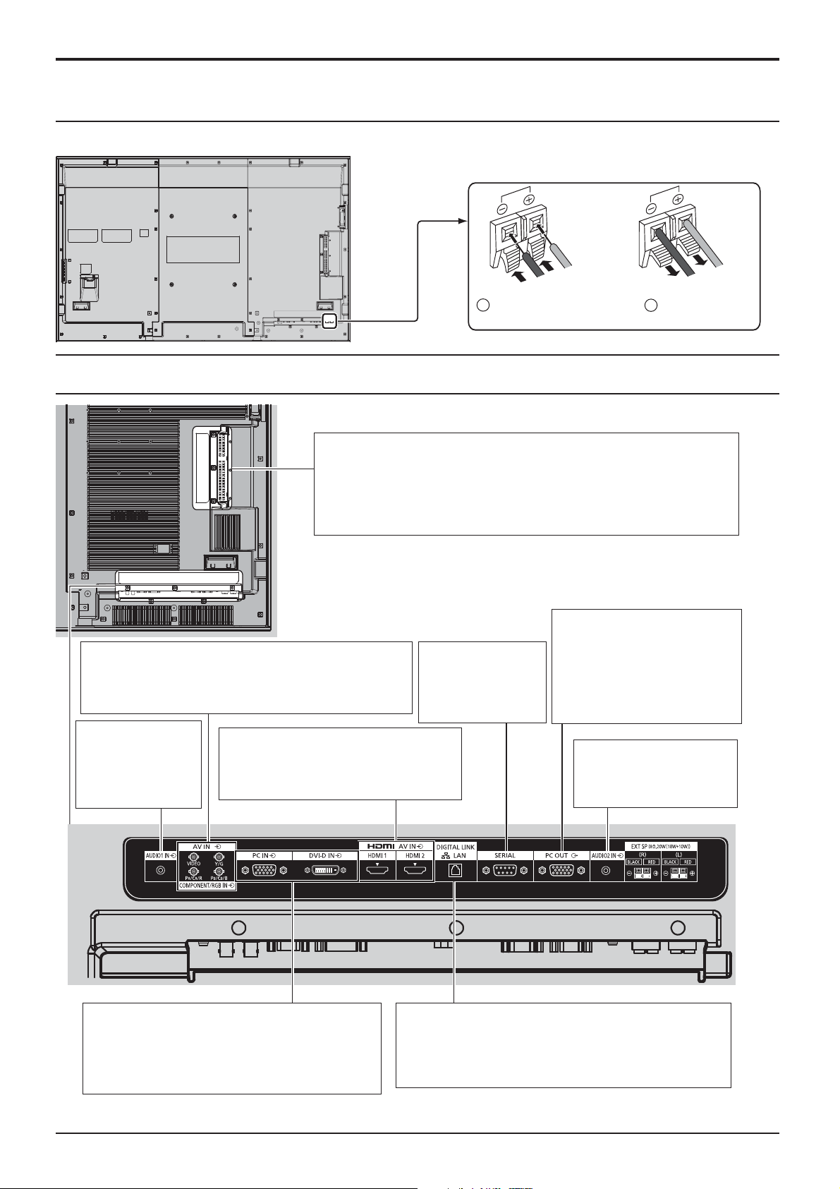
Speaker connection
Please use 8 /10 W speaker.
Connections
Video equipment connection
SLOT: Terminal board (optional accessories) insert slot
(see page 4)
Note:
The upper side slot is for terminal board with 2-slot width. The
terminal board with 1-slot width does not function when installed in
the upper side slot.
AV IN (VIDEO): Composite Video Input Terminal
(see page 12)
COMPONENT/RGB IN: Component/RGB Video Input
Terminal (see page 12)
AUDIO 1 IN:
Audio input terminal
shared with VIDEO
and COMPONENT/
RGB IN. (see page 12)
AV IN (HDMI 1, HDMI 2): HDMI Input
Terminal (see page 12)
Connect to video equipment such as
VCR or DVD player.
SERIAL:
Serial Control Terminal.
Control the Display
by connecting to
PC. (see page 15)
Red
Black
1
While pressing the lever,
insert the core wire.
PC OUT:
Monitor Out Terminal.
Video signals being
reproduced on the display
are output to another sub
monitor as PC video signals.
(see page 16)
AUDIO 2 IN:
Audio input terminal
shared with DVI-D IN and
PC IN. (see page 13, 14)
Black
2
Return the lever.
Red
PC IN:
DVI-D IN: DVI-D Input Terminal (see page 13)
*
DIGITAL LINK is technology that enables signals such as audio and video to be transmitted using twisted pair cables.
For details, see the Operating Instructions - “Network Operations”.
PC Input Terminal
Connect to video terminal of PC or
equipment with Y, PB(CB) and PR(CR)
output (see page 14).
LAN, DIGITAL LINK*
Connect to a DIGITAL LINK input terminal network
to control the Display. Alternatively, connect to a
device that sends video and audio signals via the
DIGITAL LINK terminal. (see page 17)
11
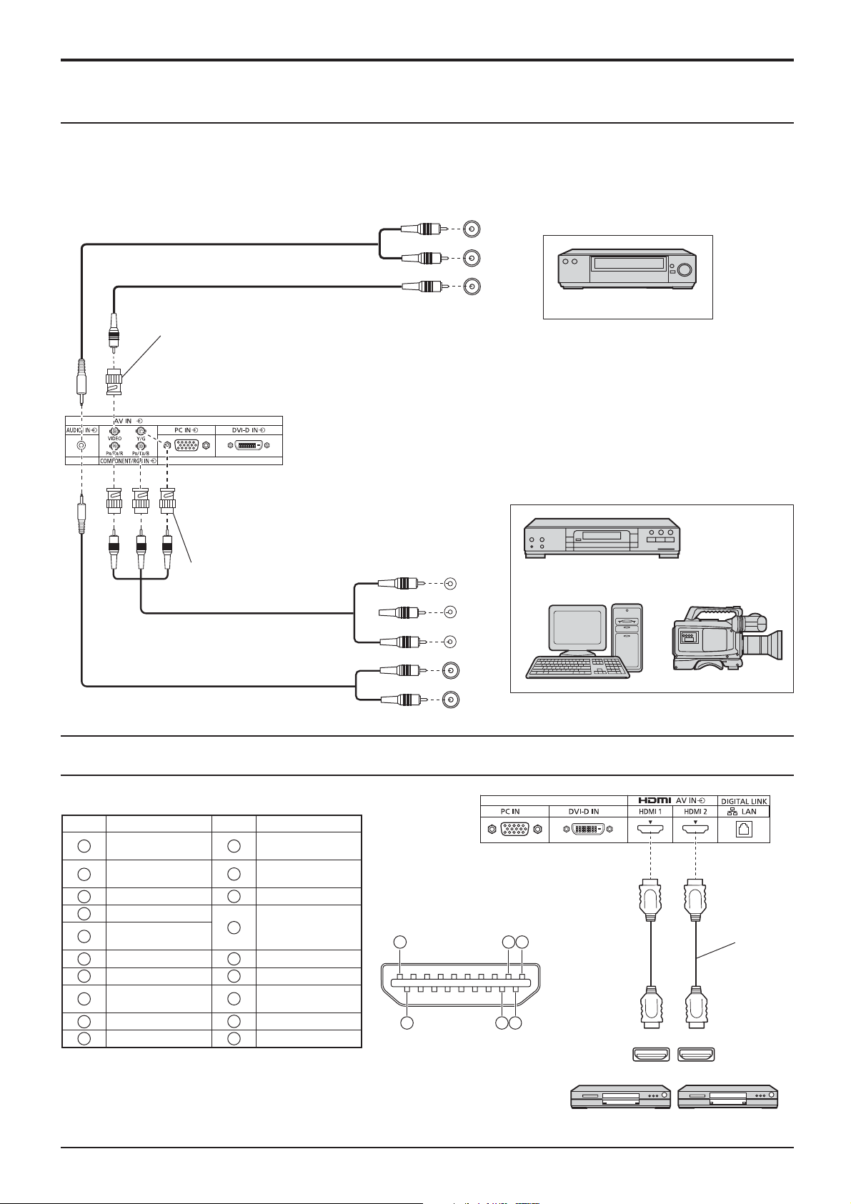
Connections
VIDEO and COMPONENT / RGB IN connection
Note:
Additional equipment, cables and adapter plugs
shown are not supplied with this set.
Stereo mini plug (M3)
L
R
AUDIO
OUT
VIDEO
OUT
VCR
VCR
Pin-BNC
Adapter plug
AUDIO 1 IN:
Shared with VIDEO and
COMPONENT/RGB IN
Pin-BNC
Adapter plug
Notes:
• Change the “Component/RGB-in select” setting in the “Setup”
menu to “Component” (when Component signal connection)
or “RGB” (when RGB signal connection). (see page 68)
• Signals input to COMPONENT/RGB IN terminals correspond
to Sync on G or Sync on Y.
DVD Player
Y
PB
PR
L
R
OUT
AUDIO
OUT
, Y , P B , P R
Computer
RGB Camcorder
HDMI connection
[Pin assignments and signal names]
Pin No.
Signal name
1
T.M.D.S Data2+
T.M.D.S Data2
2
Shield
3
T.M.D.S Data2-
4
T.M.D.S Data1+
T.M.D.S Data1
5
Shield
6
T.M.D.S Data1-
7
T.M.D.S Data0+
T.M.D.S Data0
8
Shield
9
T.M.D.S Data0-
10
T.M.D.S Clock+
Pin No.
13
14
15
16
17
18
19
Note:
Additional equipment and HDMI cable shown are not supplied with this set.
12
Signal name
T.M.D.S Clock
11
Shield
12
T.M.D.S ClockCEC
Reserved
(N.C. on device)
SCL
SDA
DDC/CEC
Ground
+5V Power
Hot Plug Detect
4
3 1
2
19
18
HDMI
AV OUT
HDMI
AV OUT
DVD player
HDMI
cable
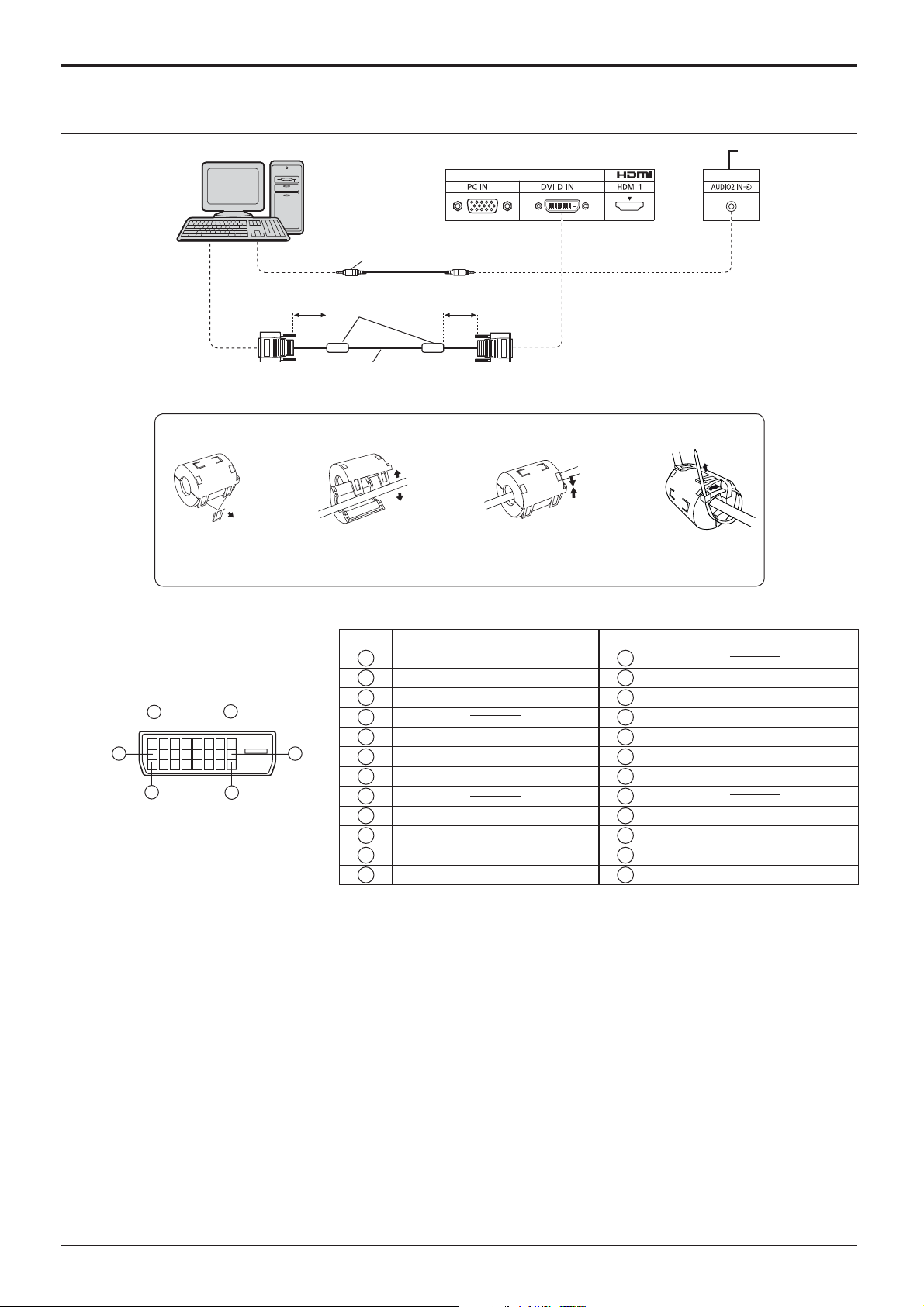
DVI-D IN connection
Connections
PC with DVI-D
video out
Installing the Ferrite core
1.
Pull back the tabs
(in two places)
Less than
1.97 inch (5 cm)
DVI-video cable (Within 5 m)
2.
Stereo mini plug (M3)
Ferrite core
(supplied)
Open the
Ferrite core
Less than
1.97 inch (5 cm)
3.
Route the
cable through
and close
Shared with PC IN.
4.
Fix the Ferrite
core with the
cable tie
DVI-D Input Connector
Pin Layouts
1
9
17
8
24
Connection port view
16
Pin No.
Signal Name
T.M.D.S. data 2-
1
T.M.D.S. data 2+
2
T.M.D.S. data 2 shield
3
4
5
DDC clock
6
DDC data
7
8
T.M.D.S. data 1-
9
T.M.D.S. data 1+
10
T.M.D.S. data 1 shield
11
12 24
Pin No.
13
14
15
16
17
18
19
20
21
22
23
Signal Name
+5 V DC
Ground
Hot plug detect
T.M.D.S. data 0T.M.D.S. data 0+
T.M.D.S. data 0 shield
T.M.D.S. clock shield
T.M.D.S. clock+
T.M.D.S. clock-
Notes:
• Additional equipment and cables shown are not supplied with this set.
• Use the DVI-D cable complying with the DVI standard. Image deterioration may occur depending on the length or
the quality of the cable.
13
Connections
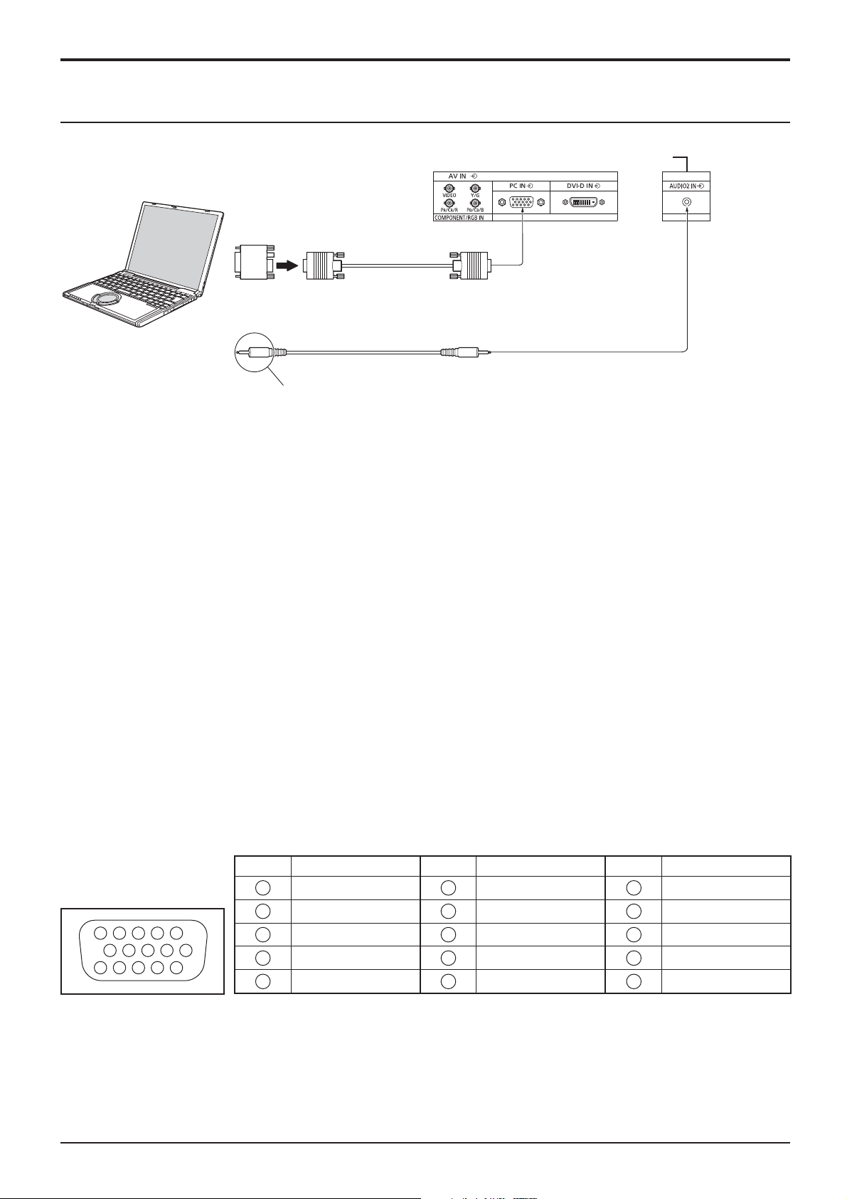
PC Input Terminals connection
COMPUTER
Conversion adapter
(if necessary)
RGB
PC cable
(Female)
Mini D-sub 15p
(Male)
Shared with DVI-D IN.
Audio
Connect a cable which matches
the audio output terminal on the computer.
Stereo mini plug (M3)
Notes:
• With regard to the typical PC input signals that are described in the applicable input signals list (see page 85), adjustment
values such as for the standard picture positions and sizes have already been stored in this unit. You can add up to eight
PC input signal types that are not included in the list.
• Computer signals which can be input are those with a horizontal scanning frequency of 15 to 110 kHz and vertical scanning
frequency of 48 to 120 Hz. (However, the image will not be displayed properly if the signals exceed 1,200 lines.)
• The display resolution is a maximum of 1,440 × 1,080 dots when the aspect mode is set to “4:3”, and 1,920 × 1,080
dots when the aspect mode is set to “16:9”. If the display resolution exceeds these maximums, it may not be possible
to show ne detail with suf cient clarity.
• The PC input terminals are DDC2B-compatible. If the computer being connected is not DDC2B-compatible, you will
need to make setting changes to the computer at the time of connection.
• Some PC models cannot be connected to the set.
• There is no need to use an adapter for computers with DOS/V compatible Mini D-sub 15P terminal.
• The computer shown in the illustration is for example purposes only.
• Additional equipment and cables shown are not supplied with this set.
• Do not set the horizontal and vertical scanning frequencies for PC signals which are above or below the speci ed
frequency range.
• Component Input is possible with the pin 1, 2, 3 of the Mini D-sub 15P Connector.
• Change the “Component/RGB-in select” setting in the “Setup” menu to “Component”
(when Component signal connection) or “RGB” (when RGB signal connection). (see page 68)
Signal Names for Mini D-sub 15P Connector
Pin No. Signal Name Pin No. Signal Name Pin No. Signal Name
4 5
10
15 14 13 12 11
1
2
1
2
3
6 7 8 3 9
4
5
R (PR/CR)
G (Y)
B (PB/CB)
NC (not connected)
GND (Ground)
Pin Layout for PC Input
Terminal
14
6
7
8
9
10
GND (Ground)
GND (Ground)
GND (Ground)
+5 V DC
GND (Ground)
11
NC (not connected)
12
13
14
15
HD/SYNC
SDA
VD
SCL
Connections
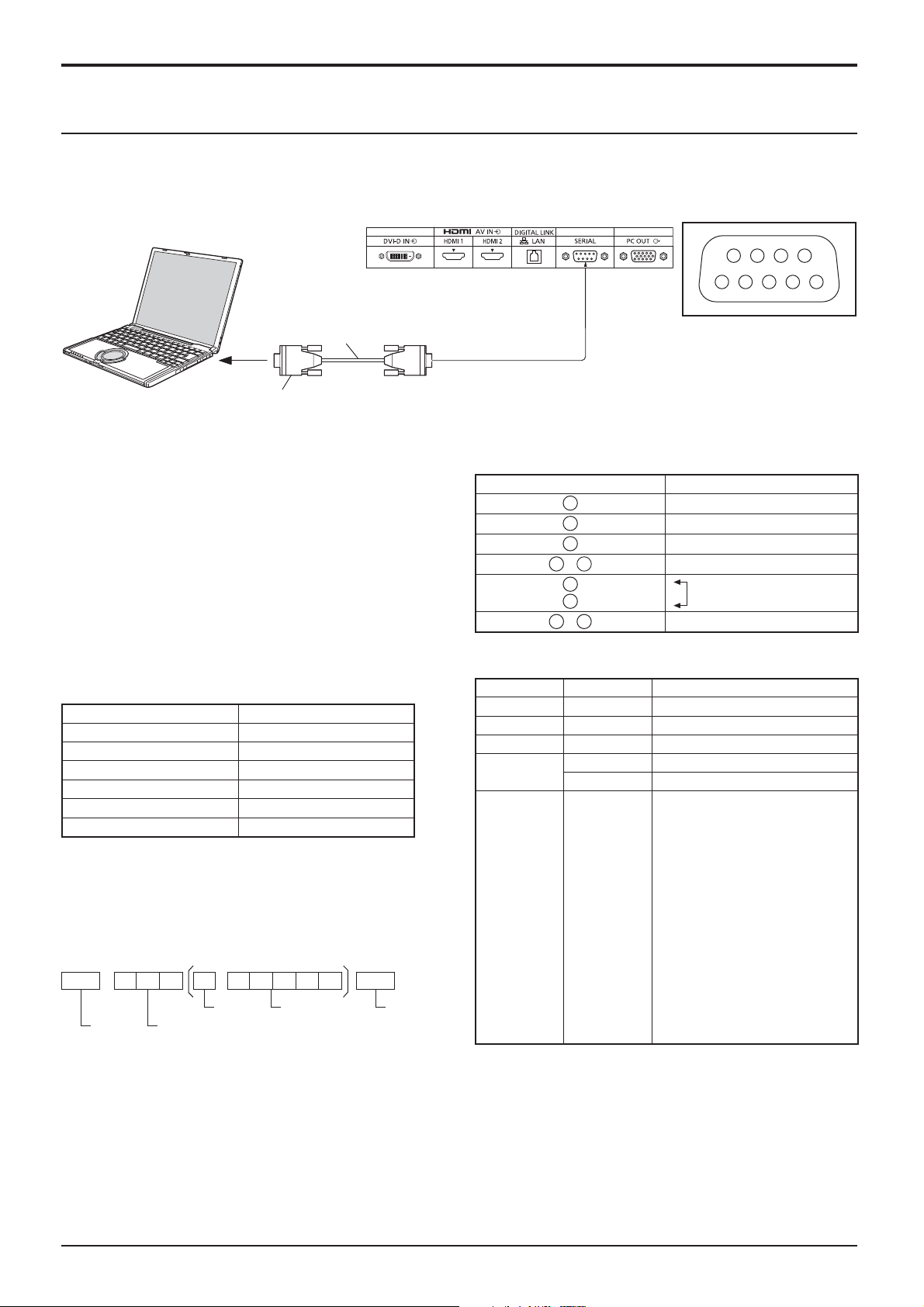
SERIAL Terminals connection
The SERIAL terminal is used when the Display is controlled by a computer.
Note: To use serial control for this unit, make sure to set the “Control I/F Select” in the “Network Settings” menu to
“RS-232C”. (refer to “Operating Instructions, Network Operations”)
COMPUTER
(Male)
6789
13452
RS-232C Straight cable
D-sub 9p
(Female)
Notes:
•
Use the RS-232C straight cable to connect the computer to the Display.
• The computer shown is for example purposes only.
• Additional equipment and cables shown are not supplied
with this set.
The SERIAL terminal conforms to the RS-232C interface
speci cation, so that the Display can be controlled by a
computer which is connected to this terminal.
The computer will require software which allows the
sending and receiving of control data which satis es the
conditions given below. Use a computer application such
as programming language software. Refer to the
documentation for the computer application for details.
Communication parameters
Signal level RS-232C compliant
Synchronization method Asynchronous
Baud rate 9600 bps
Parity None
Character length 8 bits
Stop bit 1 bit
Flow control None
Basic format for control data
The transmission of control data from the computer
starts with a STX signal, followed by the command, the
parameters, and lastly an ETX signal in that order. If
there are no parameters, then the parameter signal does
not need to be sent.
STX C1 C2 C3 P1 P2 P3 P4: P5 ETX
Start
(02h)
Colon Parameter(s)
3-character
command (3 bytes)
(1 - 5 bytes)
End
(03h)
Notes:
• If multiple commands are transmitted, be sure to wait for
the response for the rst command to come from this unit
before sending the next command.
• If an incorrect command is sent by mistake, this unit will
send an “ER401” command back to the computer.
• S1A and S1B of Command IMS are available only when
a dual input terminal board is attached.
• Consult your local Panasonic dealer for detail instructions
on command usage.
Pin layout for SERIAL Terminal
Signal names for D-sub 9P connector
Pin No. Details
2
3
5
4
6
•
7
8
1
9
•
R X D
T X D
GND
Non use
(Shorted in this set)
NC
These signal names are those of computer speci cations.
Command
Command Parameter Control details
PON None Power ON
POF None Power OFF
AVL ** Volume 00 - 63
AMT
IMS None
0 Audio MUTE OFF
1 Audio MUTE ON
Input select (toggle)
SL1
S1A
S1B
VD1
YP1
HM1
HM2
DV1
PC1
DL1
MG1
MV1
WB1
SLOT input (SLOT INPUT)
SLOT input (SLOT INPUT A)
SLOT input (SLOT INPUT B)
VIDEO input (VIDEO)
COMPONENT/RGB IN input
(COMPONENT)
HDMI 1 input (HDMI1)
HDMI 2 input (HDMI2)
DVI-D IN input (DVI)
PC IN input (PC)
DIGITAL LINK input (DIGITAL LINK)
Miracast input (Miracast(TM))
Memory veiwer input
(MEMORY VIEWER)
WhiteBoard input (WHITEBOARD)
With the power off, this display responds to PON
command only.
15

Connections
PC OUT connection
The image being reproduced on the display including the image input from video equipment and the contents drawn
on the whiteboard can be displayed on another sub monitor.
To use the function, set “Monitor Out” to “On” in “Setup”. (see page 66)
Note: Setting it to “On” will adjust the “Picture” menu values to the standard values.
Sub monitor
Computer, DVD player and
other video equipment
(Female)
USB memory
(To be viewed in Memory
Viewer)
(Male)
Mini D-sub 15p cable
(Commercially available)
Input signals and drawn images that can be output
Input signal / Drawn image Output signal
HDMI input signal (HDMI 1, HDMI 2)
HDCP (copy protection) not supported
DVI input signal (DVI-D IN)
HDCP (copy protection) not supported
PC input signal (PC IN)
When “Component/RGB-in select” is set to
“RGB”
1,920 x 1,080@50 Hz or
1,920 x 1,080@60 Hz
1,920 x 1,080@50 Hz or
1,920 x 1,080@60 Hz
1,920 x 1,080@50 Hz or
1,920 x 1,080@60 Hz
Whiteboard screen 1,920 x 1,080@60 Hz
Memory Viewer screen (MEMORY VIEWER) 1,920 x 1,080@60 Hz
Notes:
• The aspect ratio of the output signal is changed so that it can be shown on the screen.
• The following input signals cannot be output.
Component input (COMPONENT/RGB IN)
Composite video input (VIDEO)
Miracast image (Miracast(TM))
Wireless Manager (Panasonic APPLICATION)
PC input terminal
Pin Layout and Signal Names of Monitor Out Terminal (Mini-D-sub 15P)
Pin No. Signal Name Pin No. Signal Name Pin No. Signal Name
4 5
10
15 14 13 12 11
1
2
6 7 8 3 9
1
2
3
4
NC (not connected)
5
GND (Ground)
R
G
B
6
7
8
9
10
GND (Ground)
GND (Ground)
GND (Ground)
+5 V DC
GND (Ground)
16
11
NC (not connected)
12
NC (not connected)
13
14
15
NC (not connected)
HD
VD
Connections
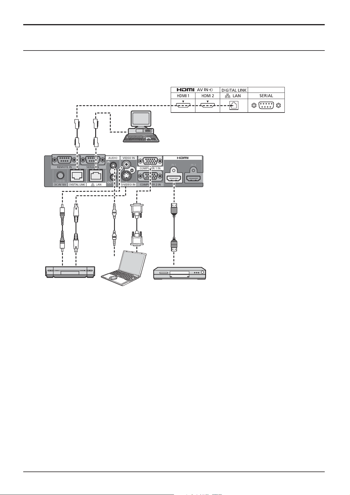
Example connection using the DIGITAL LINK Terminal
A twisted pair cable transmitter such as the Panasonic Digital Interface Box (ET-YFB100G) uses twisted pair cables
to transmit inputted video and audio signals, and these digital signals can be input to the Display via the DIGITAL
LINK terminal.
Display Connection Terminals
Control
Computer
When a Panasonic ET-YFB100G is used
Video Cassette Recorder DVD Player
Computer
Note:
When connecting with DIGITAL LINK, be sure to con gure each of the “Network Settings” settings.
For the cautions for DIGITAL LINK setting and connection, refer to “Operating Instructions - Network Operations”.
17

Power On / Off
Connecting the AC cord plug to the Display.
Connecting the plug to the Wall Outlet
Notes:
• Main plug types vary between countries. The power
plug shown at right may, therefore, not be the type
tted to your set.
• When disconnecting the AC cord, be absolutely sure
to disconnect the AC cord plug at the socket outlet
rst.
Press the Power switch on the Display to turn the set
on: Power-On.
Power switch
Power Indicator: Green
[Starting up the touch screen and network]
It takes some time for the touch screen and network
to start up just after the power is turned on.
During that time, “Touch Screen Settings”, “Network
Settings” in the “Setup” menu is grayed out and
cannot be set.
Press the button on the remote control to turn the Display off.
Power Indicator: Red (standby)
Press the
Power Indicator: Green
Turn the power to the Display off by pressing the
the Display is on or in standby mode.
Note:
During operation of the power management function, the power indicator turns
orange in the power off state.
button on the remote control to turn the Display on.
Power Indicator Remote Control Sensor
switch on the unit, when
18
Power On / Off
When rst switching on the unit
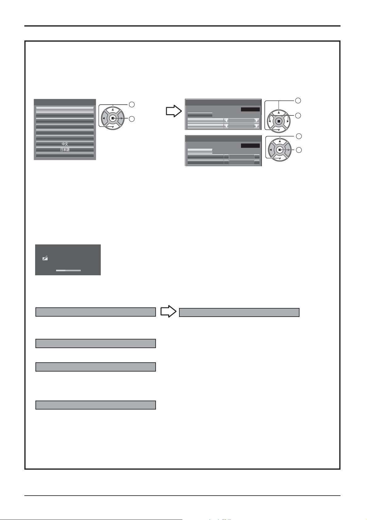
Following screen will be displayed when the unit is turned on for the rst time.
Use the remote control to make the settings. Pressing the buttons on the main unit or multi-touch operation will
not work.
OSD Language
OSD Language
English (UK)
Deutsch
Français
Italiano
Español
ENGLISH (US)
1
Select the
language.
2
Set.
Day/Time Settings
Day/Time Settings
Time MON 99:99
Set
Day
Time
Day/Time Settings
Time TUE 99:99
Set
Day TUE
MON
18:00
18:00Time
Notes:
• Once the items are set, the screens won't be displayed when switching on the unit next time.
• After the setting, the items can be changed in the following menus.
OSD Language (see page 67)
Day/Time Settings (see page 58)
Power ON message
The following message may be displayed when turning the unit power ON:
WhiteBoard Startup screen
WhiteBoard
Now Loading...
1
Select “Day”
or “Time”.
2
Setup “Day”
or “Time”.
1
Select “Set”.
2
Set.
When the power is turned ON with the Input switch of the WHITEBOARD, the built-in WhiteBoard starts up.
Touch screen connection status display
When not connected to a computer via USB
Initializing Touch Screen...
Touch Screen detected.
Touch operation of the display is possible after this
When connected to a computer via USB
Touch Screen connected to external device.
message appears.
No activity power off Precautions
’No activity power off’ is enabled.
If “No activity power off” in Setup menu is set to “Enable”, a warning message is displayed every time the
power is turned ON. (see page 67)
Power Management Information
Last turn off due to 'Power management'.
If “Power management” is functioned, an information message is displayed every time the power is turned ON.
(see page 63)
These message displays can be set with the following menu: Options menu
Power On Message (No activity power off)
(see page 75)
Power On Message (Power Management)
(see page 75)
19
Selecting the input signal
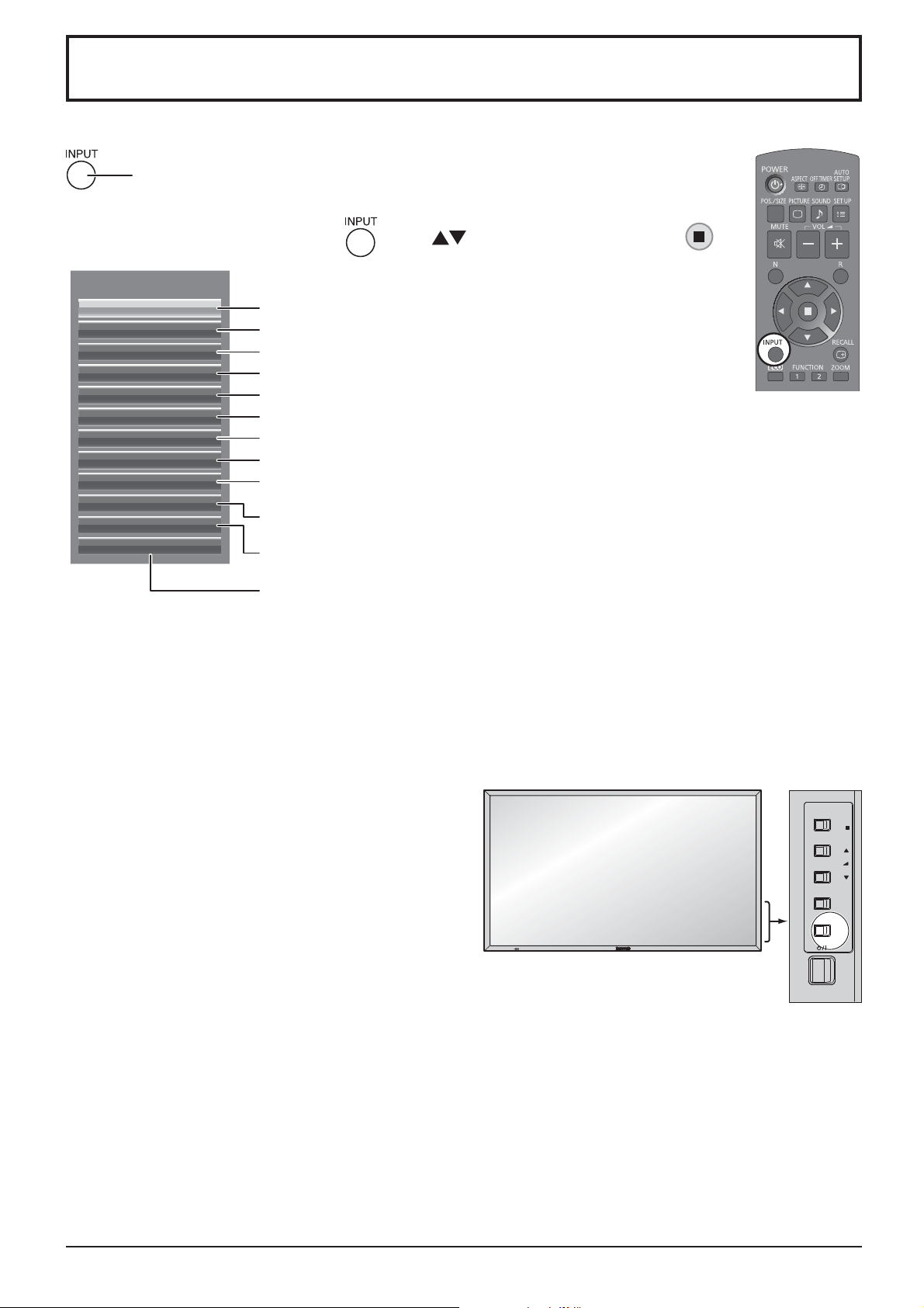
Press to select the input signal to be played back from the equipment which has been
connected to the Display.
Alternatively you can press , press to select the input and press .
INPUT
HDMI1
HDMI2
SLOT INPUT
VIDEO
COMPONENT
PC
DVI
DIGITAL LINK
Miracast(TM)
Panasonic APPLICATION
MEMORY VIEWER
WHITEBOARD
HDMI input in HDMI 1 terminal
HDMI input in HDMI 2 terminal
Input signal in a Terminal Board*
1
Composite video input in VIDEO terminal
Component/RGB input in COMPONENT/RGB IN terminal*
Computer's signal input in PC IN terminal
DVI-D input in DVI-D IN terminal
DIGITAL LINK input in DIGITAL LINK terminal
Select this input when using the Miracast function. (
Select this input when using “Wireless Manager” via wired/wireless LAN.
Select this input when using the Memory Viewer function. (
see
2
page 45)
see
page 32)
The screen switches WHITEBORAD input*3.
see
(
page 37)
*1 “SLOT INPUT” appears when an optional Terminal Board is connected.
When a Terminal Board with dual input terminals is connected, “SLOT INPUT A” and “SLOT INPUT B” will appear.
When a Terminal Board incompatible with the Display is installed, “Non-Compatible Function Board” is displayed.
*2 “COMPONENT” may be displayed as “RGB” depending on the setting of “Component/RGB-in select”.
(see page 68)
*3 The WHITEBOARD input can be selected when “Touch Screen” of “Touch Screen Settings” is “On”.
Notes:
• Selecting is also possible by pressing the INPUT button
on the unit.
• Outputs the sound as set in “Audio input select” in the
Options menu. (see page 77)
• Select to match the signals from the source connected
to the component/RGB input terminals. (see page 68)
• Image retention (image lag) may occur on the LCD
display panel when a still picture is kept on the panel for
an extended period. To prevent such a problem, using
the screensaver is recommended. (see page 61)
• The connection of the Wireless Manager is interrupted if
the input is switched from Panasonic APPLICATION to
Miracast(TM) or MEMORY VIEWER.
The connection of Miracast is interrupted if the input is
switched from Miracast(TM) to Panasonic APPLICATION
or MEMORY VIEWER.
Please check the setting again after switching the input.
ENTER/
+
VOL
-
MENU
INPUT
/
/
20
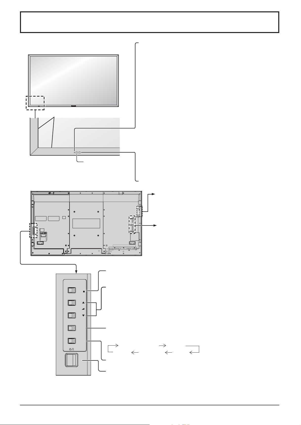
Basic Controls
Main Unit
Touch panel IR transmission part
Installed on the four sides of the display panel.
Remote control
sensor
Power Indicator
The Power Indicator will light.
• Power-OFF ....Indicator not illuminated (The unit will still
consume some power as long as the power
cord is still inserted into the wall outlet.)
• Standby ........Red
Orange (When “Slot power” is set to “On” and
Terminal Board is installed. See page 74)
Orange (Depending on the type of the function board
installed, when the power is supplied to the slot)
Orange (When “Control I/F Select” is set to “DIGITAL
LINK/LAN” or “Wireless Network Standby” is set to “On”.
Refer to “Operating Instructions, Network Operations”)
Orange (When “Quick Launch” is set to “On”. See page 59)
• Power-ON ...... Green
• HDMI1 Power management
HDMI2 Power management
.........................
Orange (With HDMI1 or HDMI2 input signal. See page 63)
* These functions are not supported by TH-80LFB70E.
• PC Power management (DPMS)
......................... Orange (With PC input signal. See page 63)
• DVI-D Power management
......................... Orange (With DVI input signal. See page 63)
Note:
If the power indicator is orange, power consumption during standby
is generally larger than that of when the power indicator is red.
Brightness Sensor
Detects the brightness in the viewing environment. (see page 63)
USB (VIEWER):
Connect to USB memory. (see page 31)
USB (TOUCH): When using the “WhiteBoard
Software” from the supplied CD-ROM,
connect the computer via USB cable.
(see page 44)
SLOT: Terminal board (optional accessories) insert
slot (see page 4 )
Note:
The upper side slot is for terminal board with 2-slot
width. The terminal board with 1-slot width does not
function when installed in the upper side slot.
ENTER/
/
+
VOL
-
/
MENU
INPUT
Enter / Aspect button
(see page 23, 46)
Volume Adjustment
Volume Up “+” Down “–”
When the menu screen is displayed:
“+” : press to move the cursor up
“–” :
press to move the cursor down
(see page 46)
MENU Screen ON / OFF
Each time the MENU button is pressed, the menu screen will switch. (see
page 46)
Normal Viewing Picture
Sound Pos. /Size
Setup
INPUT button (INPUT signal selection)
(see page 20)
Main Power On / Off Switch
21
Basic Controls
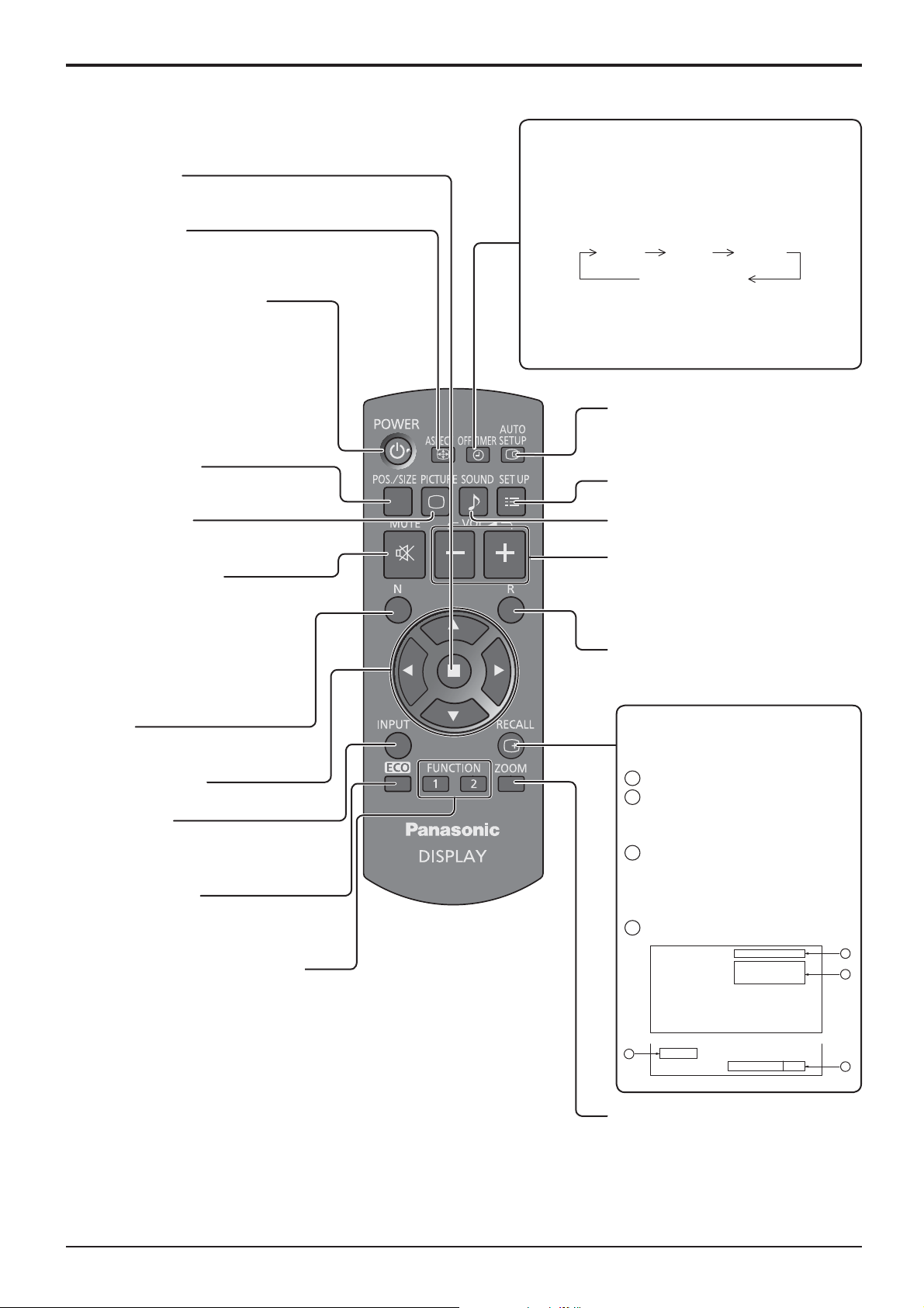
Remote Control Transmitter
ACTION button
Press to make selections.
ASPECT button
Press to adjust the aspect.
(see page 23)
Standby (ON / OFF) button
The Display must rst be plugged into
the wall outlet and turned on at the
power switch (see page 18).
Press this button to turn the Display
On, from Standby mode. Press
it again to turn the Display Off to
Standby mode.
POS./SIZE button
(see page 48)
OFF TIMER button
The Display can be preset to switch to stand-by
after a xed period. The setting changes to 30
minutes, 60 minutes, 90 minutes and 0 minutes
(off timer cancelled) each time the button is
pressed.
30 min 60 min
90 min
0 min (Cancel)
When three minutes remain, “Off timer 3 min”
will ash.
The off timer is cancelled if a power interruption
occurs.
AUTO SETUP button
Automatically adjusts the position/
size of the screen. (see page 48)
SET UP button (see page 57)
PICTURE button
(see page 51)
Sound mute On / Off
Press this button to mute the
sound.
Press again to reactivate sound.
Sound is also reactivated when
power is turned off or volume level
is changed.
N button
(see page 50, 51, 52, 56)
POSITION buttons
INPUT button
Press to select Input signal
sequentially. (see page 20)
ECO MODE (ECO)
Press to change the ECO MODE
setup status. (see page 63)
FUNCTION buttons (FUNCTION)
(see page 65)
SOUND button (see page 56)
Volume Adjustment
Press the Volume Up “+” or Down “–”
button to increase or decrease the
sound volume level.
R button (see page 46)
Press the R button to return to
previous menu screen.
RECALL button
Press the “RECALL” button to display
the current system status.
Input label
1
Aspect mode (see page 23)
2
Audio input (see page 77)
Pro le name (see page 55)
Off timer
3
The off timer indicator is
displayed only when the off
timer has been set.
Clock display (see page 74)
4
PC
COMPONENT
Memory name: MEMORY2
4:3
1
2
22
10:00
4
Off timer
90min
Digital Zoom (see page 24)
3
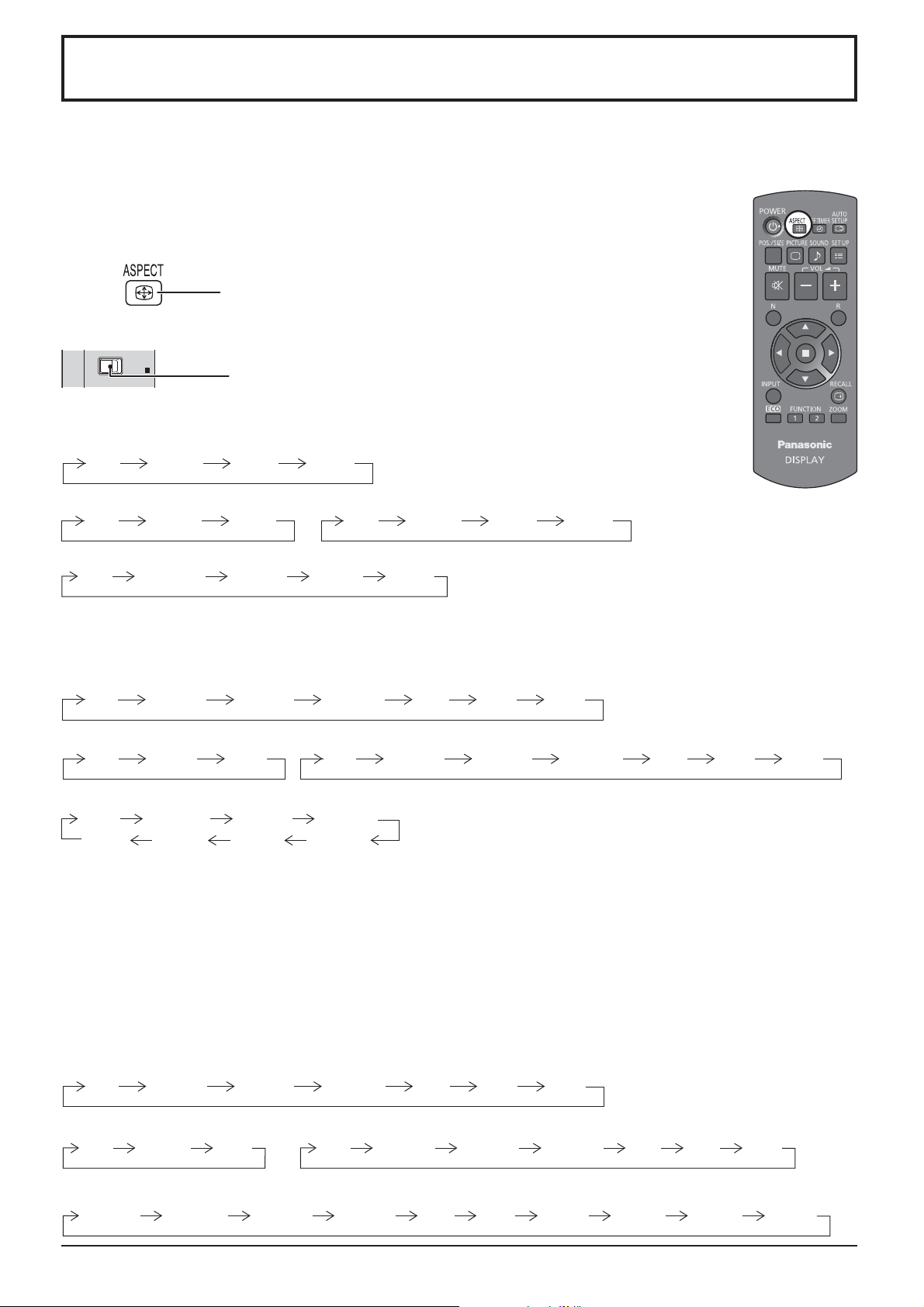
ASPECT Controls
The Display will allow you to enjoy viewing the picture at its maximum size, including wide screen cinema format
picture.
Note:
Be aware that if you put the display in a public place for commercial purposes or a public showing
and then use the aspect mode select function to shrink or expand the picture, you may be violating
the copyright under copyright law. It is prohibited to show or alter the copyrighted materials of other
people for commercial purposes without the prior permission of the copyright holder.
Press repeatedly to move through the aspect options:
For details about the aspect mode, please see “List of Aspect Modes” (page 83).
[from the unit]
ENTER/
[For TH-80LFB70U]
For VIDEO (S VIDEO) signal input:
4:3 ZOOM JUSTFULL
For PC signal input: For SD signal input (525 (480) / 60i • 60p, 625 (575) / 50i • 50p):
4:3 ZOOM FULL 4:3 ZOOM JUSTFULL
For HD signal input [1125 (1080) / 60i • 50i • 60p • 50p • 24p • 25p • 30p • 24psF, 1250 (1080) / 50i, 750 (720) / 60p • 50p]:
4:3 H-FILL ZOOM
With the following inputs, the aspect will be xed to “FULL” and you cannot switch it.
Miracast(TM), MEMORY VIEWER, WHITEBOARD
[For TH-80LFB70E and TH-80LFB70W]
For VIDEO (S VIDEO) signal input:
4:3 Zoom1 16:9Zoom2 Zoom3 14:9 Just
For PC signal input: For SD signal input (525 (480) / 60i • 60p, 625 (575) / 50i • 50p):
4:3 Zoom 16:9
For HD signal input [1125 (1080) / 60i • 50i • 60p • 50p • 24p • 25p • 30p • 24psF, 1250 (1080) / 50i, 750 (720) / 60p • 50p]:
4:3
4:3 Full Zoom1
14:9Just
The aspect mode changes each time the ENTER button is pressed.
FULL JUST
4:3 Zoom1 16:9Zoom2 Zoom3 14:9 Just
Zoom2
16:9
Zoom3
With the following inputs, the aspect will be xed to “16:9” and you cannot switch it.
Miracast(TM), MEMORY VIEWER, WHITEBOARD
Notes:
• The aspect mode is memorized separately for each input terminal.
• Do not allow the picture to be displayed in 4:3 mode for an extended period, as this can cause a permanent image
retention to remain on the Display Panel.
All Aspect mode
Set “All Aspect” to “On” in Options menu to enable the extended aspect mode (page 74). When All Aspect mode, the aspect
mode of pictures is switched as follows. For details about the aspect mode, please see “List of Aspect Modes”. (page 83)
For VIDEO (S VIDEO) signal input:
4:3 Zoom1 16:9Zoom2 Zoom3 14:9 Just
For PC signal input:
4:3 Zoom
For HD signal input [1125 (1080) / 60i • 50i • 60p • 50p • 24p • 25p • 30p • 24psF, 1250 (1080) / 50i, 750 (720) / 60p • 50p]:
4:3 Full Zoom1 16:9 Just1Zoom2 Zoom3 14:9 Just2 4:3 (1) 4:3 (2)
16:9
For SD signal input (525 (480) / 60i
4:3 Zoom1 16:9 JustZoom2 Zoom3 14:9
•
60p, 625 (575) / 50i
•
50p):
23
Digital Zoom
This displays an enlargement of the designated part of the displayed image.
Display the operation guide.
1
Press to access Digital Zoom.
The operation guide will be displayed.
During Digital Zoom, only the following buttons can be operated.
[Remote control]
Select the area of the image to be enlarged.
2
Press on the enlargement location to select.
OFF TIMER button
VOL button
MUTE button
POSITION /
ACTION button
The cursor will move.
[Unit]
ENTER/
/
+
VOL
-
/
Exit
1
VOL button
Select the magni cation required for the enlarged display.
3
Each time this is pressed, the magni cation factor changes.
This is shown in the image being displayed.
s1
Return to normal display (quit Digital Zoom).
4
Press to exit from the Digital Zoom.
Notes:
• When power goes OFF (including “Off Timer” operation), Digital Zoom terminates.
• The Digital Zoom function cannot be selected while in the following operation state:
When WHITEBOARD input.
When two screen display.
When Screensaver (except for Negative image) is running (see page 61)
When the thumbnail view or le list view of Memory Viewer is displayed
• While Digital Zoom is in operation, “Adjusting Pos./Size” cannot be used.
s2
s3
Exit
s4
2
2
24
MULTI PIP
You can display two pictures, such as a video image and computer image, in a two-screen display.
Notes:
• If “Input lock” in Options menu is set to other than “Off”, two screen display function isn’t available (see page 73).
• 2k1k signals that are received with the Dual Link HD-SDI Terminal Board (TY-FB11DHD) cannot be displayed in
two-screen display.
MULTI PIP Settings
Set the functions and mode for two-screen display in “MULTI PIP Settings” in the Setup menu. (see page 60)
PIP Mode
There are two modes for two screen display:
Pic in Pic
Displays two input images combined.
SLOT INPUT
Pic in WHITEBOARD
Displays the built-in WhiteBoard with the other input image combined.
WHITEBOARD
PC
Note:
SD signal is displayed in 4:3 mode on the sub screen.
Main screen input
Sub screen input
Main screen is xed to WHITEBOARD.
Inputs supported for the sub screen: HDMI1/HDMI2/DVI/DIGITAL LINK/
COMPONENT/PC/VIDEO/SLOT INPUT
The following four system inputs are combined:
A Panasonic APPLICATION
B SLOT INPUT
C HDMI1/HDMI2/DVI/DIGITAL LINK/COMPONENT/PC
D VIDEO
Note:
Two screen display cannot be displayed with the same system
inputs such as HDMI1-DVI combined.
Using Two Screen Display
Set “MULTI PIP” in “MULTI PIP Settings” to “On” (see page 60).
Two screen display appears.
Using the FUNCTION button
On/Off of “MULTI PIP” switches.
“MULTI PIP Settings” menu appears.
Note:
Please use the “Function Button Settings” to set the
FUNCTION button (see page 65).
Switching Sub Screen Position Changing the Size of Sub Screen
Press to switch the sub screen position. Press to change the size of the sub screen.
Note:
Alternatively, “Sub screen size” and “Sub screen position” in “MULTI PIP Settings” can be used for the same
operation (see page 60).
25
Multi-touch Operation
The built-in touch panel function of the display enables the screen control with a nger or the supplied pen.
This section explains about the multi-touch operation on the display main unit.
Note:
To enable multi-touch operation, select “Setup” - “Touch Screen Settings” and set “Touch Screen” to “On”.
(see page 59)
Touch gestures
You can use the following touch operations.
Name Operation
Tap (single tap)
Touch once lightly
Double-tap
Touch twice
Scroll
Slide a nger
Control menu operation
Controlling the display setting menus.•
Starting the Touch Zoom mode.•
Starting the whiteboard.•
Memory Viewer operation
Showing/hiding the touch operation icons when the MEMORY VIEWER
input is selected.
You can tap the displayed icons to perform operation.
Memory Viewer see page 30
Touch Zoom operation
Enlarging the image up to about three times its normal size during
Touch Zoom.
When the image is already enlarged, the zoom rate will be returned to
100%.
Touch zoom see page 29
Touch Zoom operation
Moving the displayed position of the image while the image is enlarged.
Memory Viewer operation
Skipping forward or backward the le.
Memory Viewer see page 30
Swipe from the screen edge
Slide a nger from the screen edge
26
Control menu display
Displaying the control menu.
 Loading...