

Page 1
Operating Instructions
High Defi nition Plasma Display
Manual de instrucciones
Alta defi nición Pantalla de plasma
For more detailed instructions, refer to the Operating Instructions
on the CD-ROM.
To view the Operating Instructions on the CD-ROM, you need a
computer equipped with a CD-ROM drive, and Adobe® Reader®
(Version 7.0 or later is recommended) installed on your computer.
Depending on the operating system or settings on your computer, the
Operating Instructions may not start automatically.
In this case, open the PDF fi le under the “MANUAL” folder manually to
view the instructions.
No. de Modelo
TH-58PF20U
TH-65PF20U
Contents
Important Safety Instructions
•
FCC STATEMENT
•
Safety Precautions
•
• Maintenance
Accessories
•
Connections
•
Power ON / OFF
•
Selecting the input signal
•
Basic Controls
•
On-Screen Menu Displays
•
Using Network Function
•
Specifications
•
Panasonic Professional Flat Panel
•
Display Limited Warranty
LIMITED WARRANTY STATEMENT
•
Customer Service
•
..................................
.................................
...........................................
.............................................
............................................
..................................
.......................................
........................................
.................................
..................
......................
....................
........................
.....................
Model No.
13
15
16
18
20
21
22
....
23
24
3
4
5
6
7
8
Para obtener instrucciones más detalladas, consulte las instrucciones
de manejo contenidas en el CD-ROM.
Para ver las instrucciones de manejo contenidas en el CD-ROM, se
necesita un ordenador equipado con una unidad de CD-ROM, y que
tenga instalado Adobe® Reader® (se recomienda la versión 7.0 o
posterior).
Dependiendo del sistema operativo o de las confi guraciones del ordenador,
las instrucciones de manejo pueden no iniciarse automáticamente.
En tal caso, abra manualmente el archivo PDF en la carpeta “MANUAL” para
visualizar las instrucciones.
English
Español
Before connecting, operating or adjusting this product,
please read these instructions completely.
Please keep this manual for future reference.
Antes de conectar, utilizar o ajustar este producto,
lea completamente este manual de instrucciones;
y guárdelo para consultarlo en el futuro en caso de
ser necesario.
TQB2AA0596
Page 2
CAUTION
RISK OF ELECTRIC SHOCK
DO NOT OPEN
WARNING: To reduce the risk of electric shock, do not remove cover or back.
No user-serviceable parts inside. Refer servicing to qualifi ed service personnel.
The lightning flash with
arrow-head within a triangle
is in tend ed to tell the user
that parts inside the product
are a risk of electric shock
to per sons.
The exclamation point within
a triangle is intended to
tell the user that important
operating and servicing
instructions are in the papers
with the ap pli ance.
WARNING : To prevent damage which may result in fi re or shock hazard, do not expose this apparatus to rain
or mois ture.
Do not place containers with water (fl ower vase, cups, cosmetics, etc.) above the set.
(including on shelves above, etc.)
WARNING : 1) To prevent electric shock, do not remove cover. No user serviceable parts inside. Refer servicing to
qualifi ed service personnel.
2) Do not remove the grounding pin on the power plug. This apparatus is equipped with a three pin
grounding-type power plug. This plug will only fi t a grounding-type power outlet. This is a safety fea ture.
If you are unable to insert the plug into the outlet, contact an electrician.
Do not defeat the purpose of the grounding plug.
TH-58PF20U is ENERGY STAR
As an ENERGY STAR® Partner, Panasonic has determined that this product meets the
ENERGY STAR
2
®
compliant.
®
guidelines for energy effi ciency.
Page 3

Important Safety Instructions
1) Read these instructions.
2) Keep these instructions.
3) Heed all warnings.
4) Follow all instructions.
5) Do not use this apparatus near water.
6) Clean only with dry cloth.
7) Do not block any ventilation openings. Install in accordance with the manufacturer’s instructions.
8) Do not install near any heat sources such as radiators, heat registers, stoves, or other apparatus (including
amplifi ers) that produce heat.
9) Do not defeat the safety purpose of the polarized or grounding-type plug. A polarized plug has two blades with one
wider than the other. A grounding type plug has two blades and a third grounding prong. The wide blade or the
third prong are provided for your safety. If the provided plug does not fi t into your outlet, consult an electrician for
replacement of the obsolete outlet.
10) Protect the power cord from being walked on or pinched particularly at plugs, convenience receptacles, and the
point where they exit from the apparatus.
11) Only use attachments / accessories specifi ed by the manufacturer.
12) Use only with the cart, stand, tripod, bracket, or table specifi ed by the manufacturer, or sold with
the apparatus. When a cart is used, use caution when moving the cart / apparatus combination
to avoid injury from tip-over.
13) Unplug this apparatus during lightning storms or when unused for long periods of time.
14) Refer all servicing to qualifi ed service personnel. Servicing is required when the apparatus has been damaged
in any way, such as power-supply cord or plug is damaged, liquid has been spilled or objects have fallen into the
apparatus, the apparatus has been exposed to rain or moisture, does not operate normally, or has been dropped.
15) To prevent electric shock, ensure the grounding pin on the AC cord power plug is securely connected.
3
Page 4
FCC STATEMENT
This equipment has been tested and found to comply with the limits for a Class B digital device, pursuant to Part
15 of the FCC Rules. These limits are designed to provide reasonable protection against harmful interference in a
residential installation. This equipment generates, uses and can radiate radio frequency energy and, if not installed
and used in accordance with the instructions, may cause harmful interference to radio communications. However,
there is no guarantee that interference will not occur in a particular installation. If this equipment does cause harmful
interference to radio or television reception, which can be determined by turning the equipment off and on, the user
is encouraged to try to correct the interference by one or more of the following measures:
• Reorient or relocate the receiving antenna.
• Increase the separation between the equipment and receiver.
• Connect the equipment into an outlet on a circuit different from that to which the receiver is connected.
• Consult the dealer or an experienced technician for help.
This device complies with Part15 of the FCC Rules. Operation is subject to the following two conditions:(1) This
device may not cause harmful interference, and (2) this device must accept any interference received, including
interference that may cause undesired operation.
FCC CAUTION:
To assure continued compliance, follow the attached installation instructions and use only shielded interface
cables when connecting to computer or peripheral devices. Any changes or modifi cations not expressly
approved by Panasonic Corp. of North America could void the user's authority to operate this device.
FCC Declaration of Conformity
Model No. TH-58PF20U, TH-65PF20U
Responsible Party: Panasonic Corporation of North America
Three Panasonic Way 2F-5, Secaucus, NJ 07094
Contact Source: Panasonic Solutions Company
Panasonic Plasma Concierge 1-800-973-4390
CANADIAN NOTICE:
This Class B digital apparatus complies with Canadian ICES-003.
Note:
Do not allow a still picture to be displayed for an extended period, as this can cause a permanent image retention to
remain on the Plasma Display.
Examples of still pictures include logos, video games, computer images, teletext and images displayed in 4:3 mode.
Trademark Credits
• VGA is a trademark of International Business Machines Corporation.
• Macintosh is a registered trademark of Apple Inc., USA.
• SVGA, XGA, SXGA and UXGA are registered trademarks of the Video Electronics Standard Association.
Even if no special notation has been made of company or product trademarks, these trademarks have been fully
respected.
• HDMI, the HDMI Logo, and High-Defi nition Multimedia Interface are trademarks or registered trademarks of HDMI
Licensing LLC in the United States and other countries.
4
Page 5

Safety Precautions
CAUTION
This Plasma Display is for use only with the following optional accessories. Use with any other type of optional
accessories may cause instability which could result in the possibility of injury.
• Speakers .................................................... TY-SP58P10WK (for TH-58PF20U)
• Pedestal ..................................................... TY-ST58P20 (for TH-58PF20U)
• Mobile stand ............................................... TY-ST58PF20 (for TH-58PF20U)
• Wall-hanging bracket (angled) ................... TY-WK65PR20
• BNC Dual Video Terminal Board ................TY-FB9BD
• HD-SDI Terminal Board with audio ............TY-FB10HD
• Dual Link HD-SDI Terminal Board ..............TY-FB11DHD
• Dual HDMI Terminal Board ........................TY-FB10HMD
• DVI-D T erminal Board ................................TY-FB1 1DD
• Ir Through Terminal Board .........................TY-FB9RT
• Mate-IF Board ............................................TY-FB1 1HB
• AV Terminal Box .........................................TY-TB10A V
• Anti Glare Filter .......................................... TY-AR58P10W (for TH-58PF20U), TY -AR65P9W (for TH-65PF20U)
• T ouch Panel ............................................... TY-TP58P10S (for TH-58PF20U), TY -TP65P10S (for TH-65PF20U)
Always be sure to ask a qualifi ed technician to carry out set-up.
Small parts can present choking hazard if accidentally swallowed. Keep small parts away from young children. Discard
unneeded small parts and other objects, including packaging materials and plastic bags/sheets to prevent them from being
played with by young children, creating the potential risk of suffocation.
When using the Plasma Display
Do not bring your hands, face or objects close to the
ventilation holes of the Plasma Display.
•
Top of the Plasma Display is usually very hot due to the
high temperature of exhaust air being released through the
ventilation holes. Burns or personal injuries can happen if any
body parts are brought too close. Placing any object near the
top of the display could also result in heat damages to the object
as well as to the Display if its ventilation holes are blocked.
Be sure to disconnect all cables before moving the Plasma Display.
•
Moving the Display with its cables attached might damage
the cables which, in turn, can cause fi re or electric shock.
Disconnect the power plug from the wall outlet as a
safety precaution before carrying out any cleaning.
• Electric shocks can result if this is not done.
(All of the following accessories are manufactured by Panasonic Corporation.)
TY-SP65P11WK (for TH-65PF20U)
TY-ST65P20 (for TH-65PF20U)
Clean the power cable regularly to prevent it from
becoming dusty.
• Built-up dust on the power cord plug can increase humidity
which might damage the insulation and cause fi re. Unplug
the cord from the wall outlet and clean it with a dry cloth.
This Plasma Display radiates infrared rays, therefore it
may affect other infrared communication equipment.
Install your infrared sensor in a place away from direct
or refl ected light from your Plasma Display.
Note:
Do not allow a still picture to be displayed for an extended
period, as this can cause a permanent image retention to
remain on the Plasma Display.
Examples of still pictures include logos, video games, computer
images, teletext and images displayed in 4:3 mode.
5
Page 6

Safety Precautions
WARNING
Setup
Do not place the Plasma Display on sloped or unstable
surfaces.
• The Plasma Display may fall off or tip over.
Do not place any objects on top of the Plasma Display.
•
If water spills onto the Plasma Display or foreign objects get
inside it, a short-circuit may occur which could result in fi re or
electric shock. If any foreign objects get inside the Plasma
Display, please consult an Authorized Service Center .
Do not cover the ventilation holes.
• Doing so may cause the Plasma Display to overheat,
which can cause fi re or damage to the Plasma Display.
Transport only in upright position!
• Transporting the unit with its display panel facing upright or
downward may cause damage to the internal circuitry.
If using the pedestal (optional accessory), leave a space
of 3 15/16” (10 cm) or more at the top, left and right, and
2 3/4” (7 cm) or more at the rear , and also keep the space
between the bottom of the display and the fl oor surface.
If using some other setting-up method, follow the manual
of it. (If there is no specifi c indication of installation
dimension in the installation manual, leave a space of
3 15/16” (10 cm) or more at the top, bottom, left and right,
and 2 3/4” (7 cm) or more at the rear.)
When installing the Plasma Display vertically;
Turn up the power switch for the upward direction when you
install the Plasma Display vertically.
And set “DISPLAY ORIENTA TION” to “PORTRAIT” in SET
UP menu.
An apparatus with CLASS I construction shall be
connected to a mains socket outlet with a protective
earthing connection.
AC Power Supply Cord
The Plasma Display is designed to operate on 110 - 127
V AC, 50/60 Hz.
Ensure that the mains plug is easily accessible.
Do not use any power supply cord other than that
provided with this unit.
• Doing so may cause fi re or electric shocks.
Securely insert the power cord plug as far as it will go.
• If the plug is not fully inserted, heat may be generated
which could cause fi re. If the plug is damaged or the
wall socket plate is loose, they should not be used.
Do not handle the power cord plug with wet hands.
• Doing so may cause electric shocks.
Do not do anything that might damage the power cable.
When disconnecting the power cable, hold the plug, not
the cable.
• Do not make any modifi cations, place heavy objects on,
place near hot objects, heat, bend, twist or forcefully
pull the power cable. Doing so may cause damage to
the power cable which can cause fi re or electric shock.
If damage to the cable is suspected, have it repaired at
an Authorized Service Center.
If the Plasma Display will not be used for a long period
of time, unplug the power cord from the wall outlet.
If problems occur during use
If a problem occurs (such as no picture or no sound),
or if smoke or an abnormal odor is detected from the
Plasma Display, unplug the power cord immediately.
• Continuous use of the Display under these conditions
might cause fi re or permanent damage to the unit.
Have the Display evaluated at an Authorized Service
Center. Services to the Display by any unauthorized
personnel are strongly discouraged due to its high
voltage dangerous nature.
If water or foreign objects get inside the Plasma Display,
if the Plasma Display is dropped, or if the cabinet
becomes damaged, disconnect the power cord plug
immediately.
• A short may occur, which could cause fi re. Contact an
Authorized Service Center for any repairs that need to
be made.
Maintenance
The front of the display panel has been specially treated. Wipe the panel surface gently using only a cleaning
cloth or a soft, lint-free cloth.
• If the surface is particularly dirty, wipe with a soft, lint-free cloth which has been soaked in pure water or water in which
neutral detergent has been diluted 100 times, and then wipe it evenly with a dry cloth of the same type until the surface
is dry.
• Do not scratch or hit the surface of the panel with fi ngernails or other hard objects, otherwise the surface may become
damaged. Furthermore, avoid contact with volatile substances such as insect sprays, solvents and thinner, otherwise
the quality of the surface may be adversely affected.
If the cabinet becomes dirty, wipe it with a soft, dry cloth.
• If the cabinet is particularly dirty, soak the cloth in water to which a small amount of neutral detergent has been added
and then wring the cloth dry. Use this cloth to wipe the cabinet, and then wipe it dry with a dry cloth.
• Do not allow any detergent to come into direct contact with the surface of the Plasma Display. If water droplets get
inside the unit, operating problems may result.
• Avoid contact with volatile substances such as insect sprays, solvents and thinner, otherwise the quality of the cabinet
surface may be adversely affected or the coating may peel off. Furthermore, do not leave it for long periods in contact
with articles made from rubber or PVC.
6
Page 7
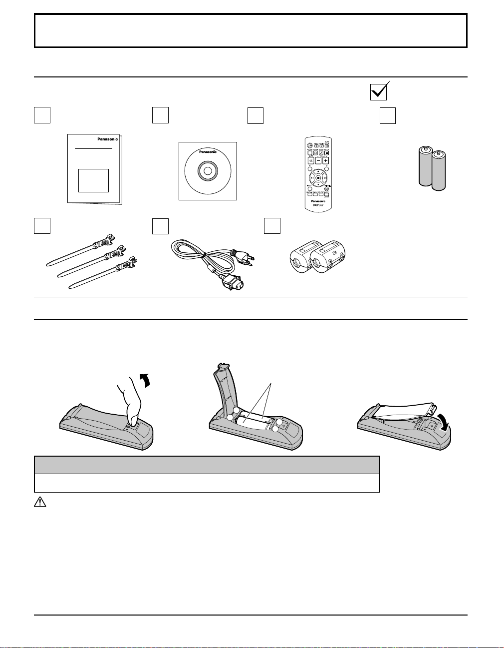
Accessories
Accessories Supplied
Check that you have the Accessories and items shown
Operating
Instruction book
TMME289 J0KG00000014
CD-ROM
(Operating
instructions)
AC cordClamper × 3
Remote Control Transmitter
N2QAYB000432
Ferrite core × 2
Use the Ferrite cores to comply with
the EMC standard.
Remote Control Batteries
Requires two AA batteries.
1. Pull and hold the hook, then
open the battery cover.
2. Insert batteries - note correct
polarity (+ and -).
“AA” size
Batteries for the
Remote Control
Transmitter
(AA Size × 2)
3. Replace the cover.
-
+
+
-
Helpful Hint:
For frequent remote control users, replace old batteries with Alkaline batteries for longer life.
Precaution on battery use
Incorrect installation can cause battery leakage and corrosion that will damage the remote control transmitter.
Disposal of batteries should be in an environment-friendly manner.
Observe the following precautions:
1. Batteries should always be replaced as a pair. Always use new batteries when replacing the old set.
2. Do not combine a used battery with a new one.
3. Do not mix battery types (example: “Zinc Carbon” with “Alkaline”).
4. Do not attempt to charge, short-circuit, disassemble, heat or burn used batteries.
5. Battery replacement is necessary when the remote control acts sporadically or stops operating the Plasma Display.
6. Do not burn or breakup batteries.
Batteries must not be exposed to excessive heat such as sunshine, fi re or the like.
7
Page 8
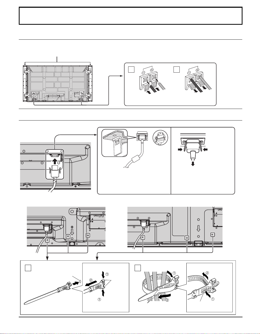
Connections
Speaker connection
When connecting the speakers, be sure to use only the optional accessory speakers.
Refer to the speaker’s Installation Manual for details on speaker installation.
Speakers (Optional accessories)
1
Black
While pressing the lever,
insert the core wire.
2
Red
Black
Return the lever.
AC cord connection and fi xing, cable fi xing
AC cord fi xing
Unplug the AC cord
Unplug the AC cord pressing the
Plug the AC cord into the display unit.
Plug the AC cord until it clicks.
Note:
Make sure that the AC cord is locked on
Using the clamper
Secure any excess cables with clamper as required.
TH-58PF20U TH-65PF20U
both the left and right sides.
two knobs.
Note:
When disconnecting the AC cord, be
absolutely sure to disconnect the AC
cord plug at the socket outlet fi rst.
Red
Attach the clamper
1
8
hole
Insert the clamper
in a hole.
To remove from the unit:
snaps
Keep
pushing both
side snaps
Bundle the cables
2
hooks
Set the
tip in the
hooks
To loosen:
knob
Keep
pushing
the knob
Page 9
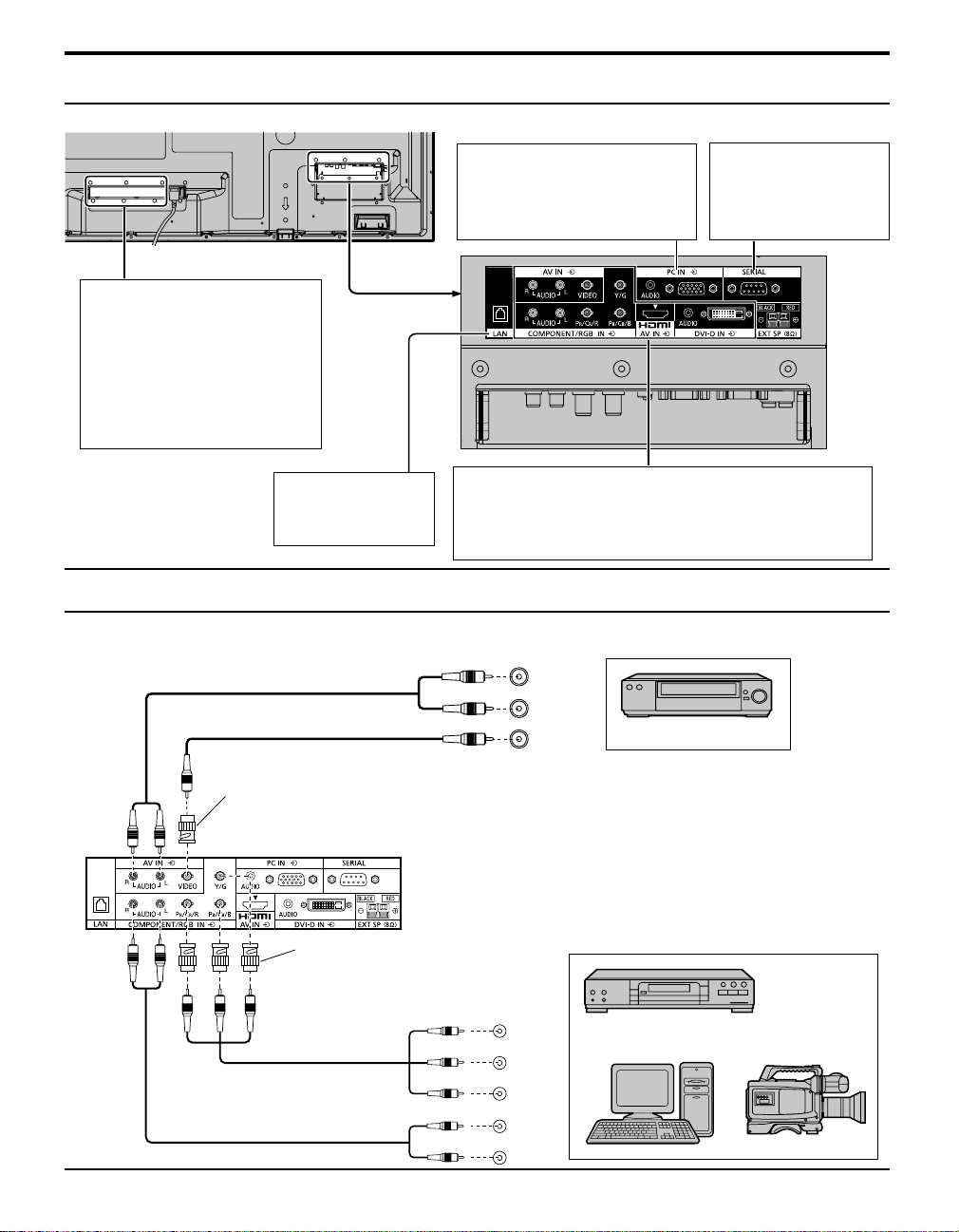
Video equipment connection
Ex. TH-65PF20U
SLOT: Terminal board (optional
accessories) insert slot
(see page 5)
Note:
The right side slot is for terminal
board with 2-slot width. The
terminal board with 1-slot width
does not function when installed
in the right side slot.
PC IN: PC Input Terminal
Connect to video terminal
of PC or equipment with
Y, PB(CB) and PR(CR)
output. (see page 11)
Connections
SERIAL: Control the
Plasma Display
by connecting
to PC.
(see page 12)
LAN: Connect to
a network to
control the unit.
(see page 20)
AV IN (VIDEO): Composite V ideo Input Terminal (see below)
COMPONENT/RGB IN:
Component/RGB Video Input Terminal (see below)
AV IN (HDMI): HDMI Input Terminal (see page 10)
DVI-D IN: DVI-D Input Terminal (see page 10)
Connect to video equipment such as VCR or DVD player.
VIDEO and COMPONENT / RGB IN connection
Note:
Additional equipment, cables and adapter plugs shown are not supplied with this set.
RCA-BNC
Adapter plug
Notes:
• Change the “COMPONENT/RGB-IN select” setting in the “SETUP”
menu to “COMPONENT” (when COMPONENT signal connection)
or “RGB” (when RGB signal connection).
RCA-BNC
Adapter plug
• Accepts only RGB signals with “SYNC ON G”.
Y
P B
P
L
R
L
R
R
AUDIO
OUT
AUDIO
VIDEO
OUT
OUT
OUT
VCR
, Y , P B , P R
Computer RGB Camcorder
DVD Player
9
Page 10
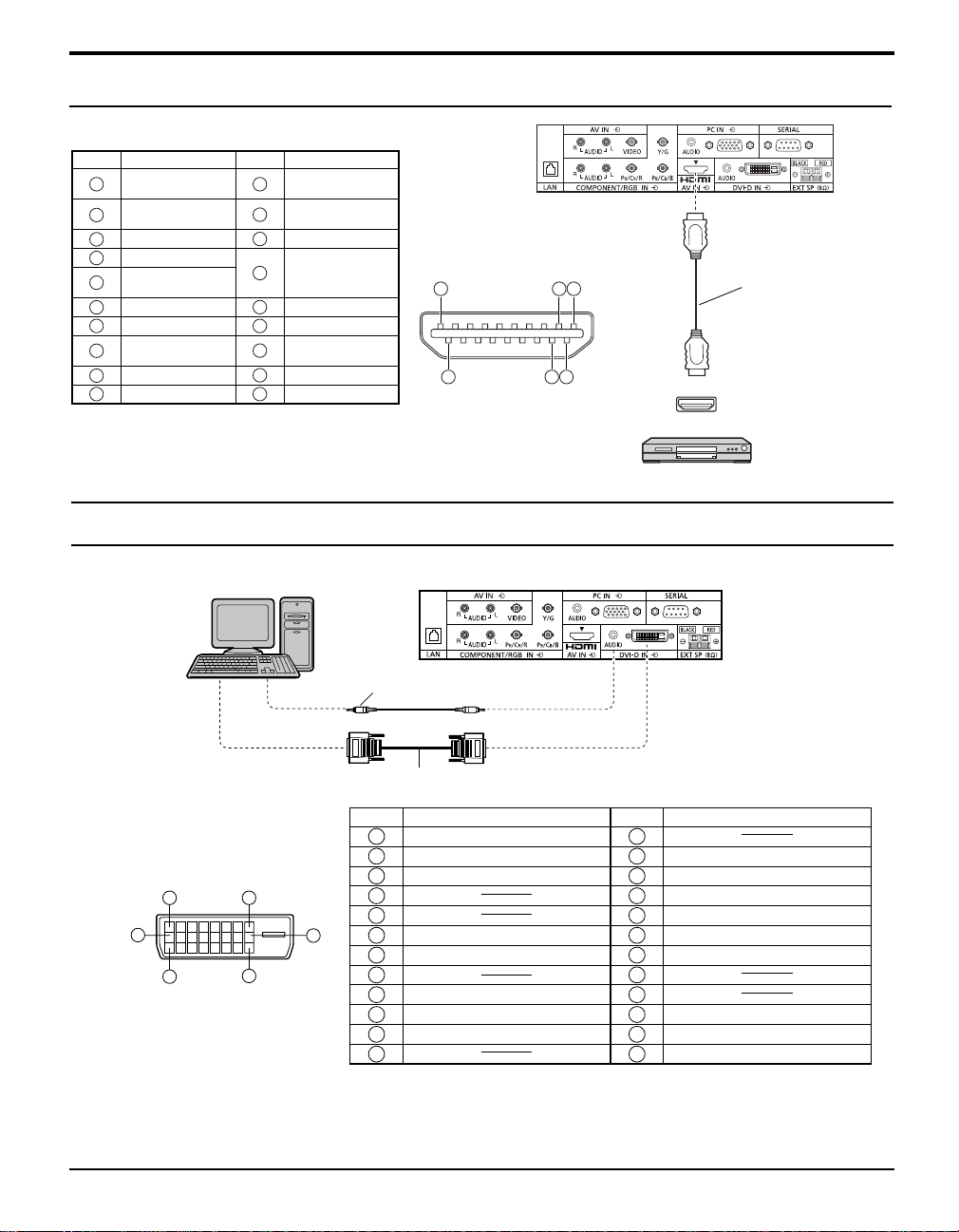
Connections
HDMI connection
[Pin assignments and signal names]
Pin No.
Signal Name
1
T.M.D.S Data2+
T.M.D.S Data2
2
Shield
3
T.M.D.S Data2-
4
T.M.D.S Data1+
T.M.D.S Data1
5
Shield
6
T.M.D.S Data1-
7
T.M.D.S Data0+
T.M.D.S Data0
8
Shield
9
T.M.D.S Data0-
10
T.M.D.S Clock+
Pin No.
11
12
13
14
15
16
17
18
19
Signal Name
T.M.D.S Clock
Shield
T.M.D.S ClockCEC
Reserved
(N.C. on device)
SCL
SDA
DDC/CEC
Ground
+5V Power
Hot Plug Detect
19
18
3 1
2
4
Note:
Additional equipment and HDMI cable shown are not supplied with this set.
DVI-D IN connection
PC with DVI-D
video out
HDMI
AV OUT
DVD player
HDMI cable
Stereo mini plug (M3)
DVI-video cable (Within 5 m)
DVI-D Input Connector
Pin Layouts
1
9
17
Connection port view
Notes:
8
24
Pin No.
Signal Name
T.M.D.S. data 2-
1
T.M.D.S. data 2+
2
T.M.D.S. data 2 shield
3
4
5
16
DDC clock
6
DDC data
7
8
T.M.D.S. data 1-
9
T.M.D.S. data 1+
10
T.M.D.S. data 1 shield
11
12 24
Pin No.
Signal Name
13
+5 V DC
14
Ground
15
Hot plug detect
16
T.M.D.S. data 0-
17
T.M.D.S. data 0+
18
T.M.D.S. data 0 shield
19
20
21
T.M.D.S. clock shield
22
T.M.D.S. clock+
23
T.M.D.S. clock-
• Additional equipment and cables shown are not supplied with this set.
• Use the DVI-D cable complying with the DVI standard. Image deterioration may occur depending on the length or
the quality of the cable.
10
Page 11
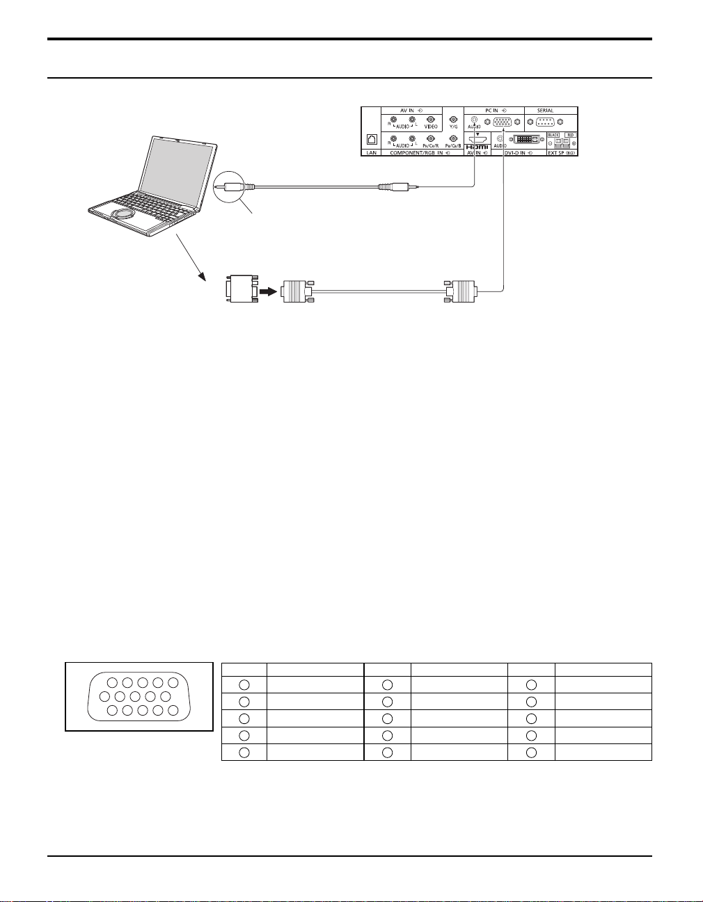
PC Input Terminals connection
COMPUTER
Connections
(Female)
Audio
Connect a cable which matches
the audio output terminal on the computer.
Conversion adapter
(if necessary)
Stereo mini plug (M3)
RGB
PC cable
Mini D-sub 15p
(Male)
Notes:
• With regard to the typical PC input signals that are described in the applicable input signals list, adjustment values such
as for the standard picture positions and sizes have already been stored in this unit. You can add up to eight PC input
signal types that are not included in the list.
• Computer signals which can be input are those with a horizontal scanning frequency of 15 to 110 kHz and vertical scanning
frequency of 48 to 120 Hz. (However, the image will not be displayed properly if the signals exceed 1,200 lines.)
• The display resolution is a maximum of 1,440 × 1,080 dots when the aspect mode is set to “4:3”, and 1,920 × 1,080
dots when the aspect mode is set to “FULL”. If the display resolution exceeds these maximums, it may not be possible
to show fi ne detail with suffi cient clarity.
• The PC input terminals are DDC2B-compatible. If the computer being connected is not DDC2B-compatible, you will need
to make setting changes to the computer at the time of connection.
• Some PC models cannot be connected to the set.
• There is no need to use an adapter for computers with DOS/V compatible Mini D-sub 15P terminal.
• The computer shown in the illustration is for example purposes only.
• Additional equipment and cables shown are not supplied with this set.
• Do not set the horizontal and vertical scanning frequencies for PC signals which are above or below the specifi ed
frequency range.
• Component Input is possible with the pin 1, 2, 3 of the Mini D-sub 15P Connector.
• Change the “COMPONENT/RGB-IN SELECT” setting in the “SET UP” menu to “COMPONENT”
(when COMPONENT signal connection) or “RGB” (when RGB signal connection).
Signal Names for Mini D-sub 15P Connector
Pin No.
1514131211
67839
1
10
45
2
Pin Layout for PC Input
Terminal
1
2
3
4
NC (not connected)
5
Signal Name
R (PR/CR)
G (Y)
B (PB/CB)
GND (Ground)
Pin No.
6
7
8
9
10
Signal Name
GND (Ground)
GND (Ground)
GND (Ground)
+5 V DC
GND (Ground)
Pin No.
11
12
13
14
15
Signal Name
NC (not connected)
SDA
HD/SYNC
VD
SCL
11
Page 12
Connections
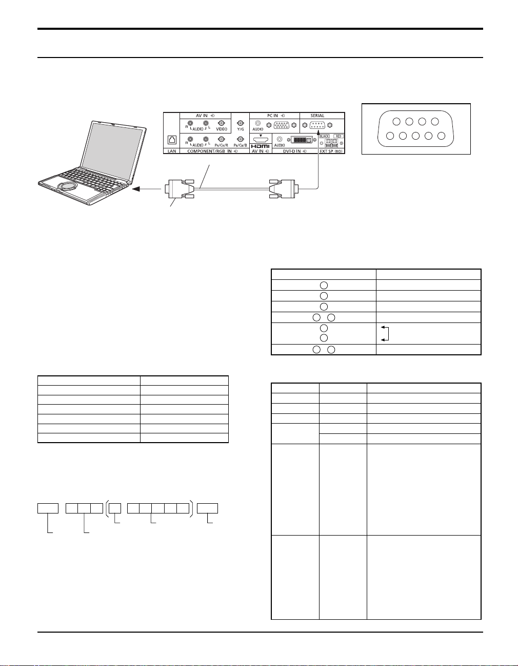
SERIAL Terminals connection
The SERIAL terminal is used when the Plasma Display is controlled by a computer.
Note:
To use serial control for this unit, make sure to set the “CONTROL I/F SELECT” in the “NETWORK SETUP” menu to “RS-232C”.
COMPUTER
(Male)
6789
13452
RS-232C Straight cable
Notes:
D-sub 9p
• Use the RS-232C straight cable to connect the computer
to the Plasma Display.
• The computer shown is for example purposes only.
• Additional equipment and cables shown are not supplied
with this set.
The SERIAL terminal conforms to the RS-232C interface
specifi cation, so that the Plasma Display can be controlled
by a computer which is connected to this terminal.
The computer will require software which allows the
sending and receiving of control data which satisfi es the
conditions given below. Use a computer application such as
programming language software. Refer to the documentation
for the computer application for details.
Communication parameters
Signal level RS-232C compliant
Synchronization method Asynchronous
Baud rate 9600 bps
Parity None
Character length 8 bits
Stop bit 1 bit
Flow control -
Basic format for control data
The transmission of control data from the computer starts with
a STX signal, followed by the command, the parameters, and
lastly an ETX signal in that order. If there are no parameters,
then the parameter signal does not need to be sent.
STX C1 C2 C3 P1 P2 P3 P4: P5 ETX
Start
(02h)
3-character
Colon Parameter(s)
command (3 bytes)
(1 - 5 bytes)
End
(03h)
Notes:
• If multiple commands are transmitted, be sure to wait for
the response for the fi rst command to come from this unit
before sending the next command.
• If an incorrect command is sent by mistake, this unit will
send an “ER401” command back to the computer.
• S1A and S1B of Command IMS are available only when a
dual input terminal board is attached.
(Female)
Pin layout for SERIAL Terminal
Signal names for D-sub 9P connector
Pin No.
2
3
5
4
6
•
7
8
1
9
•
Details
R X D
T X D
GND
Non use
(Shorted in this set)
NC
These signal names are those of computer specifi cations.
Command
Command Parameter Control details
PON None Power ON
POF None Power OFF
AVL ** Volume 00 - 63
AMT 0 Audio MUTE OFF
1 Audio MUTE ON
IMS None
SL1
S1A
S1B
VD1
YP1
Input select (toggle)
SLOT input (SLOT INPUT)
SLOT input (SLOT INPUT A)
SLOT input (SLOT INPUT B)
VIDEO input (VIDEO)
COMPONENT/RGB IN input
(COMPONENT)
HM1
DV1
PC1
DAM None
ZOOM
FULL
JUST
NORM
SJST
SNOM
SFUL
ZOM2
HDMI input (HDMI)
DVI-D IN input (DVI)
PC IN input (PC)
Screen mode select (toggle)
ZOOM (For Video/SD/PC signal)
FULL
JUST (For Video/SD signal)
4:3 (For Video/SD/PC signal)
JUST (For HD signal)
4:3 (For HD signal)
H-FILL (For HD signal)
ZOOM (For HD signal)
With the power off, this display responds to PON command only .
12
Page 13
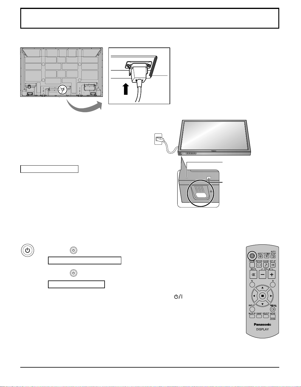
Power ON / OFF
Connecting the AC cord plug to the Plasma Display.
Connecting the plug to the Wall Outlet.
Note:
When disconnecting the AC cord, be absolutely sure to
disconnect the AC cord plug at the socket outlet fi rst.
Press the Power switch on the Plasma Display to turn the
set on: Power-On.
Power Indicator: Green
INPUT MENU ENTER/+/VOL-/
Power Indicator
Remote Control Sensor
Press the button on the remote control to turn the Plasma Display off.
Power Indicator: Red (standby)
Press the button on the remote control to turn the Plasma Display on.
Power Indicator: Green
Turn the power to the Plasma Display off by pressing the switch on the unit,
when the Plasma Display is on or in standby mode.
Note:
During operation of the power management function, the power indicator turns
orange in the power off state.
13
Page 14
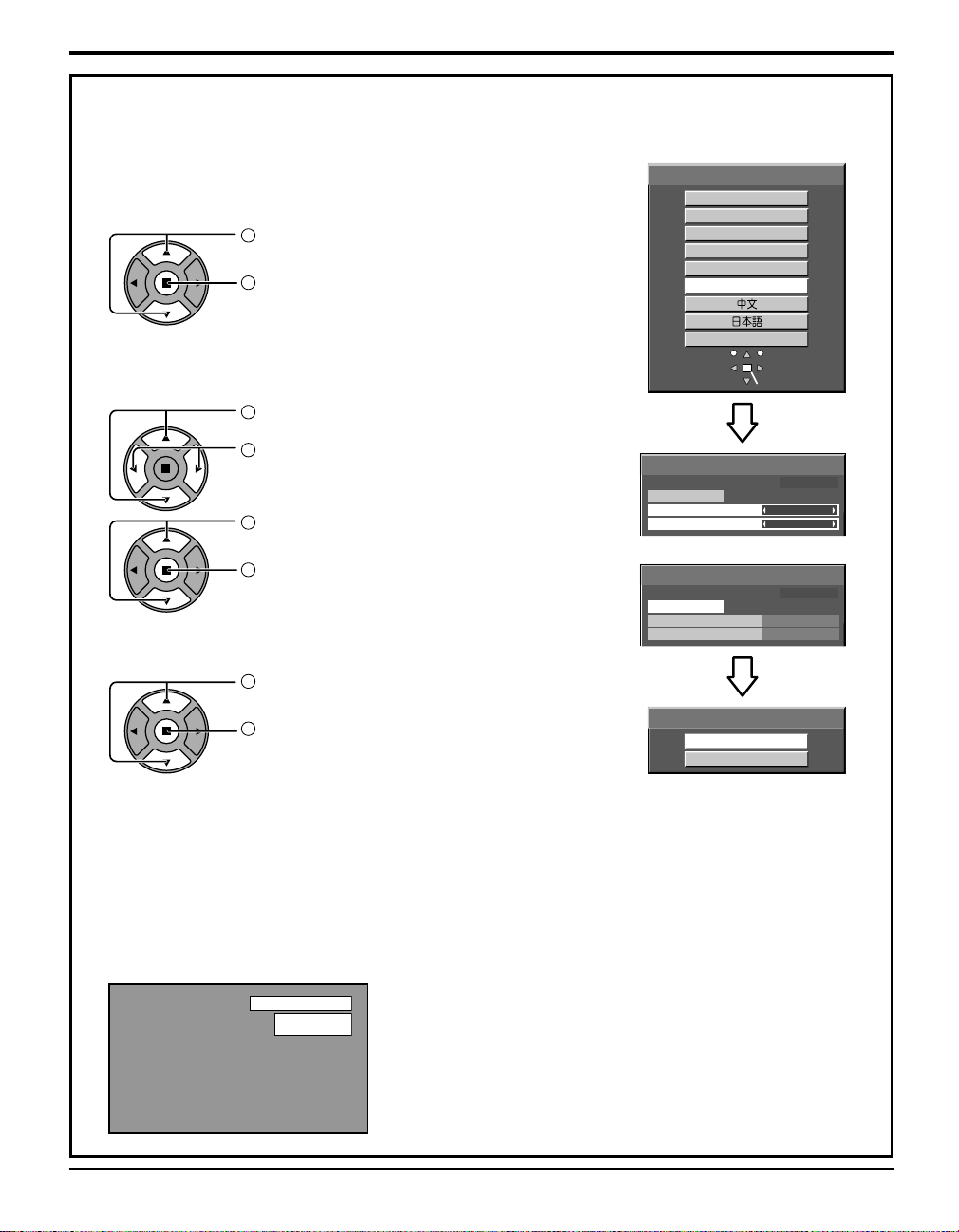
Power ON / OFF
When fi rst switching on the unit
Following screen will be displayed when the unit is turned on for the fi rst time.
Select the items with the remote control. Unit buttons are invalid.
OSD LANGUAGE
1
Select the language.
2
Set.
OSD LANGUAGE
English (UK)
Deutsch
Français
Italiano
Español
ENGLISH (US)
PRESENT TIME SETUP
1
Select “DAY” or “PRESENT TIME OF DAY”.
2
Setup “DAY” or “PRESENT TIME OF DAY”.
1
Select “SET”.
2
Set.
PRESENT TIME SETUP
PRESENT TIME OF DAY MON 99:99
SET
DAY
PRESENT TIME OF DAY
PRESENT TIME SETUP
PRESENT TIME OF DAY MON 99:99
SET
DAY
PRESENT TIME OF DAY
DISPLAY ORIENTATION
1
For vertical installation, select “PORTRAIT”.
2
Set.
DISPLAY ORIENTATION
LANDSCAPE
PORTRAIT
Notes:
• Once the items are set, the screens won't be displayed when switching on the unit next time.
• After the setting, the items can be changed in the following menus.
OSD LANGUAGE
PRESENT TIME SETUP
DISPLAY ORIENTATION
SET SELECT
MON
99:99
TUE
10:00
From the second time on, the below screen is displayed for a while (setting condition is an example).
PC
FULL
NANODRIFT
14
Page 15
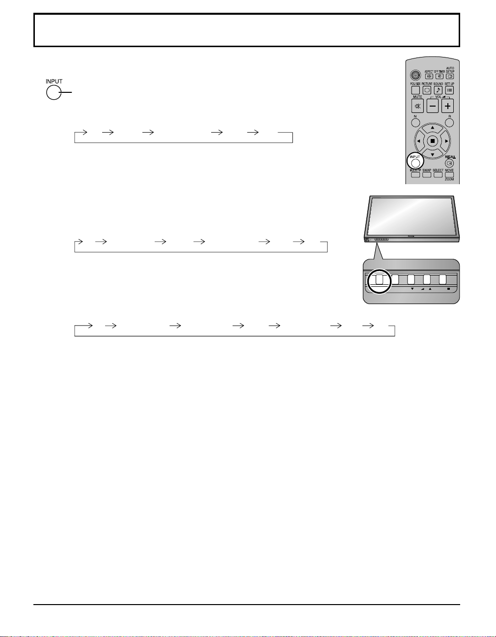
INPUT MENU ENTER/ + / VOL - /
Selecting the input signal
Press to select the input signal to be played back from the equipment which has
been connected to the Plasma Display.
Input signals will change as follows:
PC COMPONENT* DVI
VIDEO: Video input terminal in AV IN (VIDEO).
COMPONENT*: Component or RGB input terminal in COMPONENT/RGB IN.
HDMI: HDMI input terminal in AV IN (HDMI).
DVI: DVI input terminal in DVI-D IN.
PC: PC input terminal in PC IN.
* “COMPONENT” may be displayed as “RGB” depending on the setting of
“COMPONENT/RGB-IN SELECT”.
When an optional Terminal Board is installed:
PC VIDEO HDMI DVICOMPONENTSLOT INPUT
SLOT INPUT: Input terminal in Terminal Board
Note:
When a Terminal Board incompatible with the Plasma Display is installed,
“NON-COMPATIBLE FUNCTION BOARD” is displayed.
When a Terminal Board with dual input terminals is installed:
PC
SLOT INPUT A
SLOT INPUT B
HDMIVIDEO
VIDEO HDMI DVICOMPONENT
INPUT MENU ENTER/+/VOL-/
SLOT INPUT A, SLOT INPUT B: Dual input terminal in Terminal Board.
Notes:
• Selecting is also possible by pressing the INPUT button on the unit.
• Outputs the sound as set in “Audio input select” in the Options menu.
• Select to match the signals from the source connected to the component/RGB input
terminals.
• In 2 screen display, the same input mode cannot be selected for the main picture and
sub picture.
• Image retention (image lag) may occur on the plasma display panel when a still picture
is kept on the panel for an extended period. The function that darkens the screen slightly
is activated to prevent image retention, but this function is not the perfect solution to
image retention.
15
Page 16
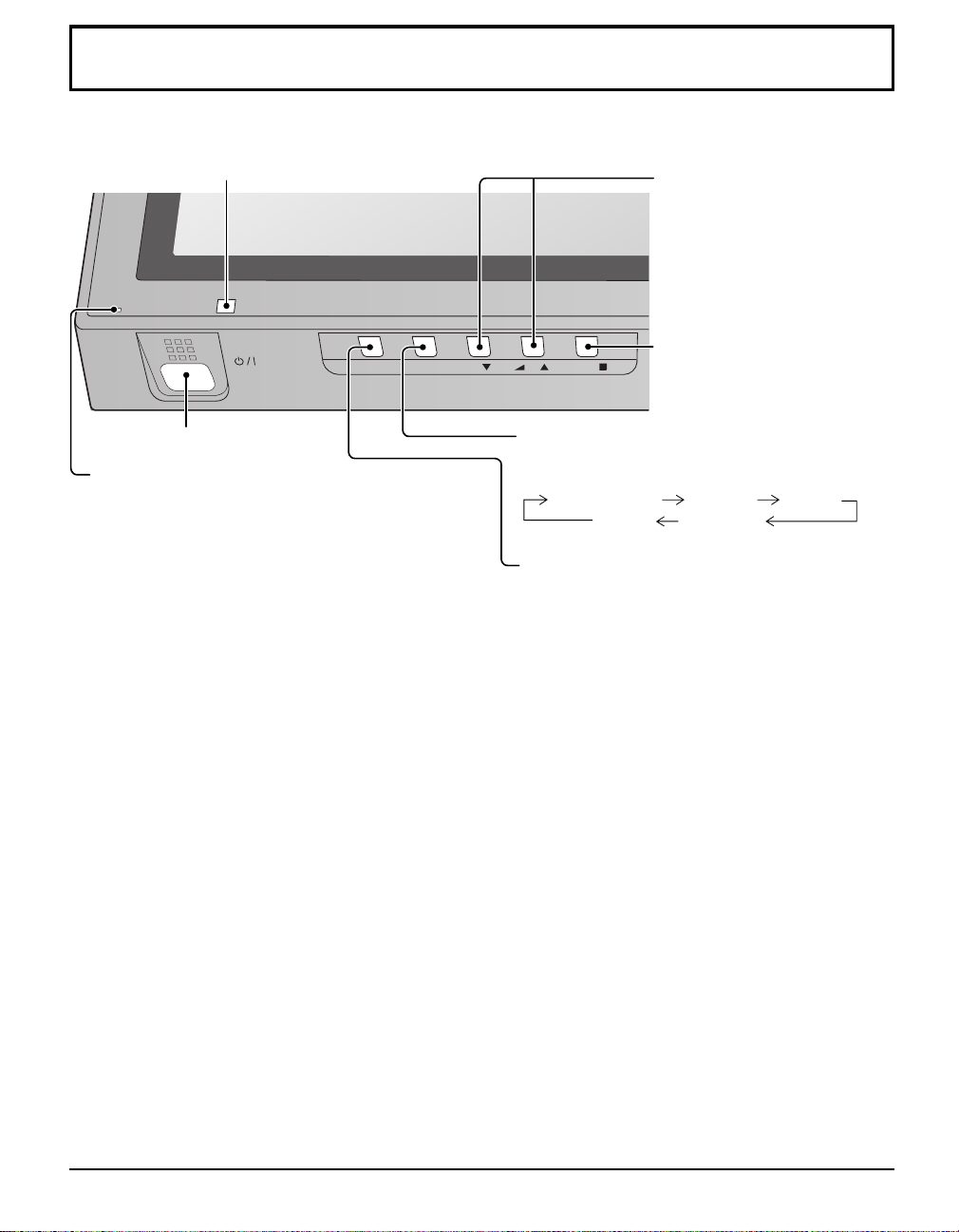
Basic Controls
Main Unit
Remote control sensor
INPUT MENU ENTER/
Main Power On / Off Switch
Power Indicator
The Power Indicator will light.
• Power-OFF ....Indicator not illuminated (The unit will
still consume some power as long as the
power cord is still inserted into the wall
outlet.)
• Standby ........Red
Orange (When “Slot power” is set to
“On”.)
Orange (Depending on the type of
the function board installed, when the
power is supplied to the slot)
Orange (When “CONTROL I/F
SELECT” is set to “LAN”.)
• Power-ON ......Green
• PC POWER MANAGEMENT (DPMS)
........................ Orange (With PC input signal.)
When this function is set to ON, it operates under the following conditions to turn the power on or off
automatically.
When no pictures (HD/VD sync signals) are detected for 30 or so seconds during PC signal input:
Power is turned off (standby); the power indicator lights up orange.
When pictures (HD/VD sync signals) are subsequently detected:
Power is turned on; the power indicator lights up green.
• DVI-D POWER MANAGEMENT
........................Orange (With DVI input signal.)
When this function is set to ON, it operates under the following conditions to turn the power on or off
automatically.
When no pictures (sync signal) are detected for 30 or so seconds during DVI signal input:
Power is turned off (standby); the power indicator lights up orange.
When pictures (sync signal) are subsequently detected:
Power is turned on; the power indicator lights up green.
Volume Adjustment
Volume Up “+” Down “–”
When the menu screen is
displayed:
“+” :
press to move the cursor up
“–” :
press to move the cursor down
(see page 18)
Enter / Aspect button
+
/VOL-/
MENU Screen ON / OFF
Each time the MENU button is pressed, the menu screen
will switch. (see page 18)
Normal Viewing PICTURE SET UP
INPUT button (Input signal selection)
(see page 15)
(see page 18)
SOUND POS. /SIZE
16
Page 17
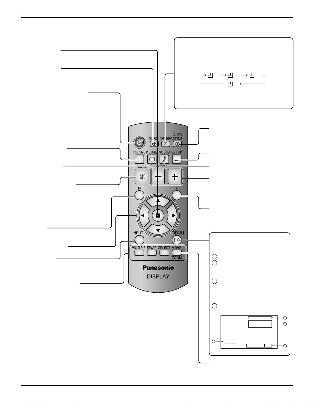
Remote Control Transmitter
ACTION button
Press to make selections.
ASPECT button
Press to adjust the aspect.
Standby (ON / OFF) button
The Plasma Display must fi rst be plugged
into the wall outlet and turned on at the
power switch (see page 13).
Press this button to turn the Plasma
Display On, from Standby mode. Press
it again to turn the Plasma Display Off to
Standby mode.
POS. /SIZE button
Basic Controls
OFF TIMER button
The Plasma Display can be preset to switch to standby after a fi xed period. The setting changes to 30
minutes, 60 minutes, 90 minutes and 0 minutes (off
timer cancelled) each time the button is pressed.
30 60
0
When three minutes remain, “OFF TIMER 3” will fl ash.
The off timer is cancelled if a power interruption
occurs.
AUTO SETUP button
Automatically adjusts the position/
size of the screen.
SET UP button
90
PICTURE button
Sound mute On / Off
Press this button to mute the sound.
Press again to reactivate sound.
Sound is also reactivated when power is
turned off or volume level is changed.
N button
POSITION buttons
INPUT button
Press to select input signal sequentially.
(see page 15)
MULTI Window buttons
SOUND button
Volume Adjustment
Press the Volume Up “+” or Down “–”
button to increase or decrease the
sound volume level.
R button
Press the R button to return to
previous menu screen.
RECALL button
Press the “RECALL” button to
display the current system status.
Input label
1
2
Aspect mode
Audio input
NANODRIFT SAVER operating
Off timer
3
The off timer indicator is
displayed only when the off
timer has been set.
Clock display
4
PC
COMPONENT
NANODRIFT
10:00
4
OFF TIMER 90
1
4:3
2
3
Digital Zoom
17
Page 18
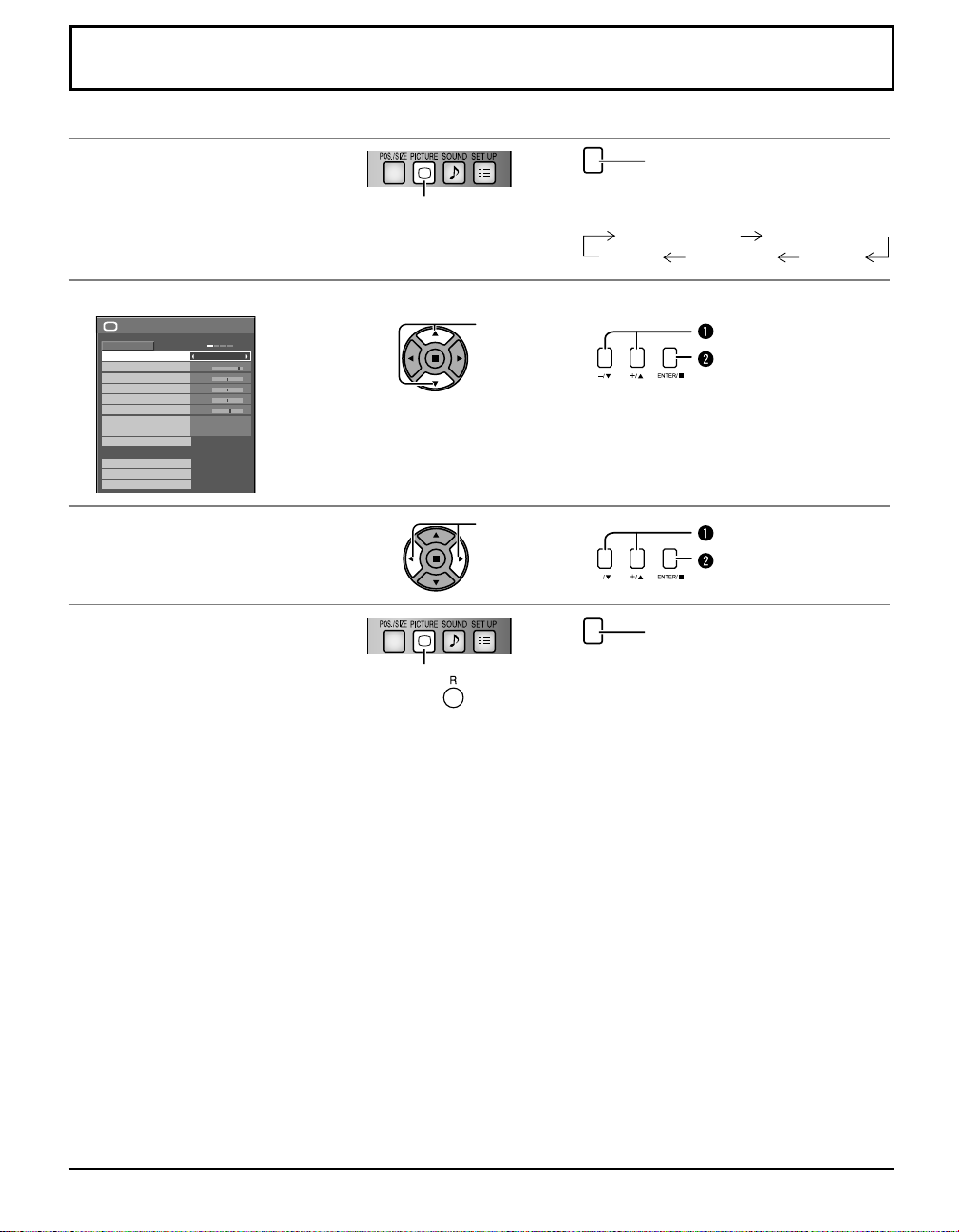
On-Screen Menu Displays
Remote Control Unit
Display the menu screen.
1
Select the item.
2
PICTURE
NORMAL
NORMALIZE
PICTURE MENU
PICTURE
BRIGHTNESS
COLOR
TINT
SHARPNESS
COLOR TEMP
COLOR MANAGEMENT
ADVANCED SETTINGS
MEMORY SAVE
MEMORY LOAD
MEMORY EDIT
Set.
3
Exit the menu.
4
STANDARD
25
0
0
0
5
NORMAL
OFF
( Example:
PICTURE menu)
Press to select.
(Example: PICTURE menu)
Select.
Adjust.
Press.
Press
to return to the previous menu.
Press several times.
MENU
Each time the MENU button is pressed, the
menu screen will switch.
Normal Viewing PICTURE
SOUND POS. /SIZE
SET UP
Select.
Press.
Adjust.
Press.
Press several times.
MENU
18
Page 19
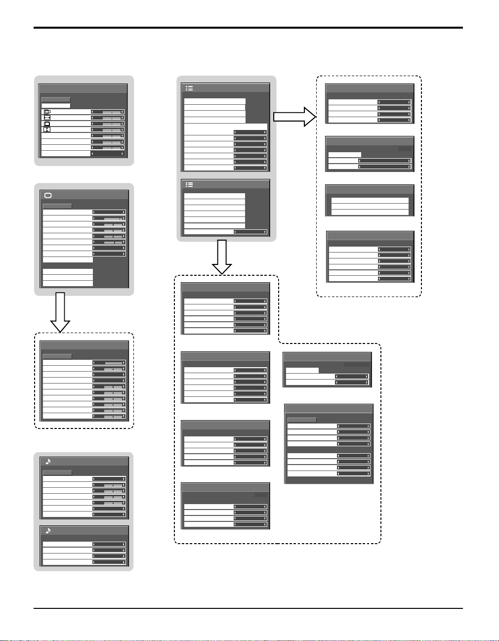
On-Screen Menu Displays
Overview
Note: Menu that cannot be adjusted is grayout. Adjustable menu changes depending on signal, input and menu setting.
POS. /SIZE
NORMAL
NORMALIZE
AUTO SETUP
H-POS
H-SIZE
V-POS
V-SIZE
DOT CLOCK
CLOCK PHASE
CLAMP POSITION
1:1 PIXEL MODE
PICTURE
NORMAL
NORMALIZE
PICTURE MENU
PICTURE
BRIGHTNESS
COLOR
TINT
SHARPNESS
COLOR TEMP
COLOR MANAGEMENT
ADVANCED SETTINGS
MEMORY SAVE
MEMORY LOAD
MEMORY EDIT
ADVANCED SETTINGS
NORMAL
NORMALIZE
BLACK EXTENSION
INPUT LEVEL
GAMMA
AGC
W/B HIGH R
W/B HIGH G
W/B HIGH B
W/B LOW R
W/B LOW G
W/B LOW B
SOUND
NORMAL
NORMALIZE
AUDIO MENU
BASS
MID
TREBLE
BALANCE
SURROUND
AUDIO OUT (PIP)
SDI SOUND OUTPUT
LEFT CHANNEL
RIGHT CHANNEL
SOUND OUT
LEVEL METER
0
0
0
0
0
0
0
OFF
STANDARD
25
0
0
0
5
NORMAL
OFF
0
0
2.2
OFF
0
0
0
0
0
0
STANDARD
0
0
0
0
OFF
MAIN
CHANNEL 1
CHANNEL 1
OFF
OFF
RGB
OFF
OFF
OFF
OFF
OFF
LANDSCAPE
1/2
)
2/2 SET UP
SIGNAL
3D Y/C FILTER (NTSC)
COLOR SYSTEM
3 : 2 PULLDOWN
NOISE REDUCTION
SCREENSAVER
PRESENT TIME OF DAY 99:99
START
FUNCTION
MODE
EXTENDED LIFE SETTINGS
EXPRESS SETTINGS
CUSTOM SETTINGS
[
VIDEO
ON
AUTO
OFF
OFF
SCROLLING BAR ONLY
OFF
RESET
]
INPUT LABEL
SLOT INPUT
VIDEO
COMPONENT
HDMI
DVI
PC
SLOT INPUT
VIDEO
COMPONENT
HDMI
DVI
PC
SET UP
SIGNAL
SCREENSAVER
EXTENDED LIFE SETTINGS
INPUT LABEL
COMPONENT/RGB-IN SELECT
POWER SAVE
STANDBY SAVE
PC POWER MANAGEMENT
DVI-D POWER MANAGEMENT
AUTO POWER OFF
OSD LANGUAGE ENGLISH (US
MULTI DISPLAY SETUP
MULTI PIP SETUP
PORTRAIT SETUP
SET UP TIMER
PRESENT TIME SETUP
NETWORK SETUP
DISPLAY ORIENTATION
MULTI DISPLA Y SETUP
MULTI DISPLAY SETUP
HORIZONTAL SCALE
VERTICAL SCALE
SEAM HIDES VIDEO
LOCATION
AI-SYNCHRONIZATION
MULTI PIP SETUP
MULTI PIP
DISPLAY MODE
TRANSPARENCY
TRANSPARENCY LEVEL
INSERT
INSERT LEVEL
OFF
× 2
× 2
OFF
A1
OFF
BLEND PIP
—
OFF
0 %
OFF
1
PRESENT TIME SETUP
PRESENT TIME OF DAY MON 99:99
SET
DAY
PRESENT TIME OF DAY
MON
99:99
NETWORK SETUP
PORTRAIT SETUP
PORTRAIT SETUP
SEAM HIDES VIDEO
VIEWING AREA
1/2
2/2
LOCATION
AI-SYNCHRONIZATION
SET UP TIMER
PRESENT TIME OF DAY 99:99
POWER ON FUNCTION
POWER ON TIME
POWER OFF FUNCTION
POWER OFF TIME
OFF
OFF
16:9
OFF
OFF
0:00
OFF
0:00
1
SAVE
DHCP
IP ADDRESS
SUBNET MASK
GATEWAY
PORT
LAN SPEED
NETWORK ID
CONTROL I/F SELECT
MAC ADDRESS
Off
192.168. 0. 8
255.255.255. 0
192.168. 0. 1
1024
Auto
0
RS-232C
--:--:--:--:--:--
19
Page 20
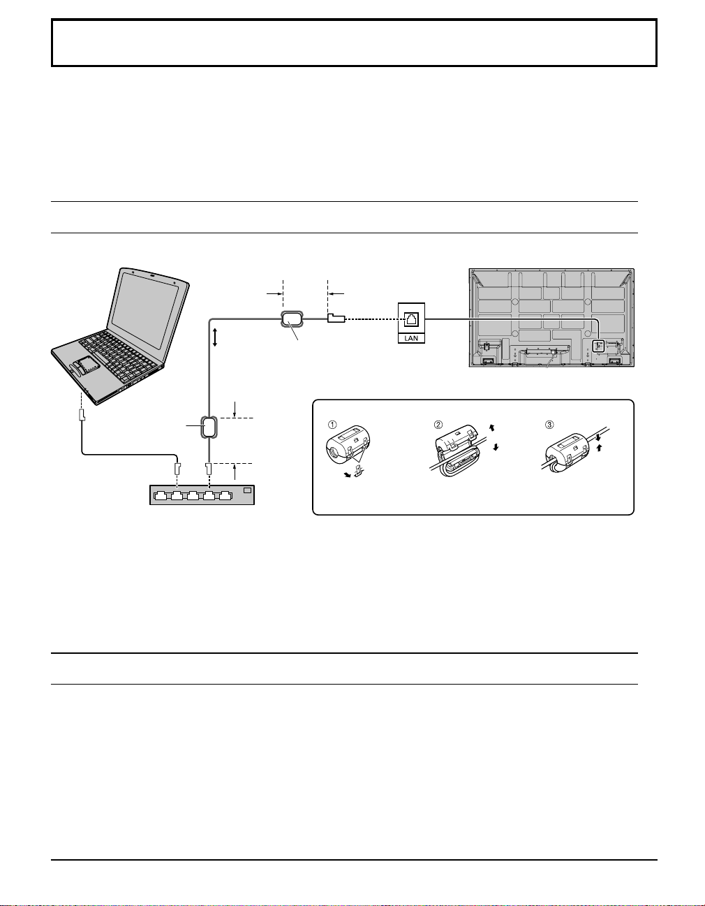
Using Network Function
This unit has a network function to control the network connected display with your computer.
Note:
T o use the network function, set each “NETWORK SETUP” setting and make sure to set the “CONTROL I/F SELECT”
to “LAN”.
When “LAN” is set, the slot power is turned on, and power indicator is lit orange under the condition of power off with
remote control (stand-by state), regardless of the “Slot power” setting.
Example of Network Connection
COMPUTER
Less
than
3.9 inch
(10 cm)
LAN cable
(not supplied)
Ferrite core
(supplied)
Hub or broadband router
Notes:
• Make sure the broadband router or hub supports 10BASE-T/100BASE-TX.
• To connect a device using 100BASE-TX, use “category 5” LAN cable.
• Touching the LAN terminal with a statically charged hand (body) may cause damage due to its discharge.
Do not touch the LAN terminal or a metal part of the LAN cable.
• For instructions on how to connect, consult your network administrator.
Less
than
3.9 inch (10 cm)
Ferrite core
(supplied)
Installing the Ferrite core
Pull back the tabs
(in two places)
Display (main unit, rear)
Open
Wind the cable
twice
Press the cable
through and close
Command Control
Network function of the unit can control the unit in the same way as serial control from a network.
Supported commands
Commands used in the serial control are supported. (see page 12)
Note:
Consult your local Panasonic dealer for detail instructions on command usage.
20
Page 21
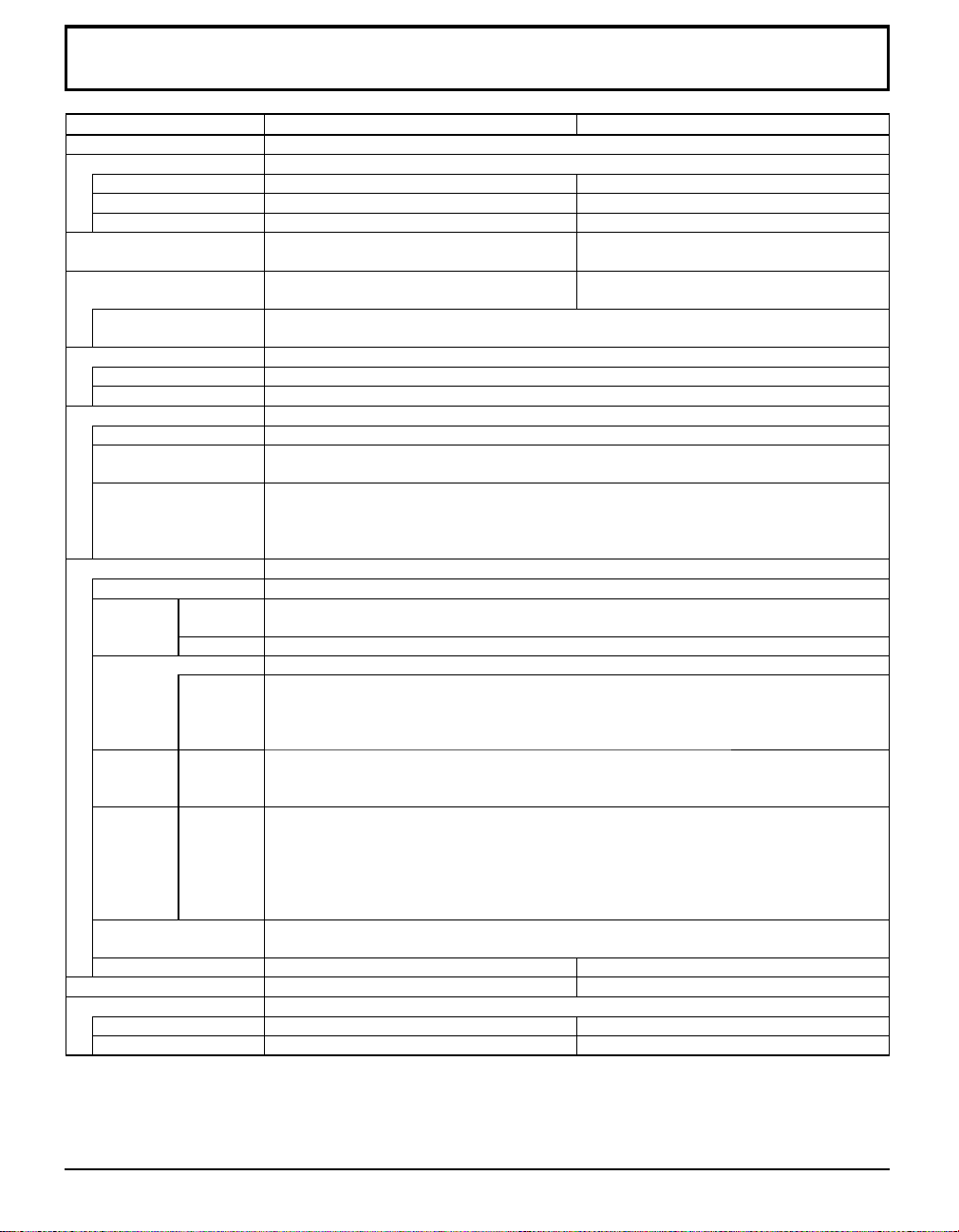
Specifi cations
TH-58PF20U TH-65PF20U
Power Source
Power Consumption
Rated Power Consumption
Stand-by condition
Power off condition
Plasma Display panel
Screen size
(No.of pixels)
Operating condition
Temperature
Humidity
Applicable signals
Color System
Scanning format
PC signals
Connection terminals
LAN RJ45 10BASE-T/100BASE-TX, compatible with PJLink™
AV IN
COMPONENT/RGB IN
DVI-D IN
PC IN
Dimensions (W × H × D)
Mass (weight)
main unit only
with speakers
AUDIO L-R
AUDIO L-R
SERIAL
EXT SP
VIDEO
HDMI
Y/G
P
B/CB/B
P
R/CR/R
AUDIO
AUDIO
Save OFF 1.0 W, Save ON 0.5 W Save OFF 1.0 W, Save ON 0.5 W
Drive method : AC type 58-inch,
50.5” (1,284 mm) (W) × 28.4” (722 mm) (H)
× 58.0” (1,473 mm) (diagonal)
NTSC, PAL, PAL60, SECAM, Modifi ed NTSC
525 (480) / 60i · 60p, 625 (575) / 50i · 50p, 750 (720) / 60p · 50p, 1125 (1080) / 60i · 60p · 50i · 50p
· 24p · 25p · 30p · 24sF, 1250 (1080) / 50i
BNC
RCA Pin jack × 2
BNC
BNC
BNC
RCA Pin jack × 2
DVI-D 24 Pin
Content Protection
Stereo mini jack (M3) × 1
High-Density Mini D-sub 15 Pin
Stereo mini jack (M3) × 1
External Control Terminal
D-sub 9 Pin RS-232C compatible
6 , 16 W [8 W + 8 W] (10 % THD) 8 , 20 W [10 W + 10 W] (10 % THD)
55.1” (1,399 mm) × 33.2” (843 mm) × 3.9” (99 mm) 61.2” (1,554 mm) × 36.5” (925 mm) × 3.9” (99 mm)
600 W 630 W
0.2 W 0.2 W
16:9 aspect ratio
approx. 99.2 lbs approx. 121.3 lbs
approx. 110.3 lbs approx. 132.3 lbs
Note:
Design and specifi cations are subject to change without notice. Mass and dimensions shown are approximate.
110 - 127 V AC, 50/60 Hz
Drive method : AC type 65-inch,
16:9 aspect ratio
56.4” (1,434 mm) (W) × 31.7” (806 mm) (H)
× 64.7” (1,645 mm) (diagonal)
2,073,600 (1,920 (W) × 1,080 (H))
[5,760 × 1,080 dots]
32 °F - 104 °F (0 °C - 40 °C)
20 % - 80 %
VGA, SVGA, XGA, SXGA
Horizontal scanning frequency 15 - 110 kHz
UXGA ···· (compressed)
Vertical scanning frequency 48 - 120 Hz
1.0 Vp-p (75 )
0.5 Vrms
TYPE A Connector
with sync 1.0 Vp-p (75 )
0.7 Vp-p (75 )
0.7 Vp-p (75 )
0.5 Vrms
Compliance with DVI Revision 1.0
Compatible with HDCP 1.1
0.5 Vrms
Y or G with sync 1.0 Vp-p (75 )
Y or G without sync 0.7 Vp-p (75 )
P
/B: 0.7 Vp-p (75 )
B/CB
P
/R: 0.7 Vp-p (75 )
R/CR
HD/VD: 1.0 - 5.0 Vp-p (high impedance)
0.5 Vrms
21
Page 22
(for the U.S.A and Puerto Rico)
Panasonic Solutions Company
Unit of Panasonic Corporation of
North America
Three Panasonic Way 2F-5
Secaucus, NJ 07094
Panasonic Professional Flat Panel Display
Panasonic Solutions Company. (referred to as “the
Warrantor”) will repair this product and all included
accessories with new or refurbished parts, free of
charge in the USA or Puerto Rico, of the original
purchase in the event of a defect in materials or workmanship as follows:
Models or Parts
Professional Flat
Panel Display
On-site or carry-in service in the USA and Puerto Rico
may be obtained during the warranty period by contacting
Panasonic
1-800-973-4390.
Solutions
Part
Warranty
2 Years 2 Years
Company Service toll free at
Limited Warranty
Labor
Warranty
antenna, inadequate signal pickup, maladjustment of
consumer controls, improper operation, power line surge,
improper voltage supply, lighting damage, or service by
anyone other than an authorized repair facility, or
damage that is attributable to acts of God.
LIMITS AND EXCLUSIONS
There are no express warranties except as listed above.
THE WARRANTOR SHALL NOT BE LIABLE FOR
INCIDENTAL OR CONSEQUENTIAL DAMAGES
(INCLUDING, WITHOUT LIMITION, DAMAGE
TO DISCS) RESULTING FROM THE USE OF THIS
PRODUCT, OR ARISING OUT OF ANY BREACH OF
THE WARRANTY. ALL EXPRESS AND IMPLIED
WARRANTIES, INCLUDING THE WARRANTIES
OF MERCHANTABILITY AND FITNESS FOR
PARTICULAR PURPOSE, ARE LIMITED TO THE
APPLICABLE WARRANTY PERIOD SET FORTH
ABOVE.
This warranty is extended only to the original purchaser
and is non transferable. A purchase receipt or other
proof of date of original purchase will be required before
warranty service is rendered.
This warranty only covers failures due to defects in
materials or workmanship, which occur during normal
use. The warranty does not cover damage which occur
in shipment, or failures which are caused by products
not supplied by the warrantor, or failures which result
from improper installation, set-up adjustments, improper
In the USA and Puerto Rico
22
Some states do not allow the exclusion or limitation
of incidental or consequential damages, or limitations
on how long an implied warranty lasts, so the above
exclusions or limitations may nor apply to you. This
warranty gives you specific legal rights and you may
other rights, which vary from state to state.
If you have a problem with this product that is not
handled to your satisfaction, then write the Consumer
Affairs Department at the Company address indicated
above.
FOR SERVICE
CALL TOLL FREE
1-800-973-4390
Page 23
Panasonic Canada Inc.
5770 Ambler Drive, Mississauga, Ontario L4W 2T3
LIMITED WARRANTY STATEMENT
(for Canada)
Panasonic Canada Inc. (also known as PCI) warrants this product to be free of
defects in material and workmanship under normal use during the applicable
warranty coverage period described below. PCI agrees to repair, or at its option,
exchange, any part that becomes defective. However, the product must be
purchased and serviced in Canada. The product or part that shows evidence of
defect must be delivered prepaid or carried in to an authorized Panasonic Broadcast
Service Center. This warranty does not cover shipping costs.
The warranty coverage period is one year for both parts and labour beginning with
the date of original end user purchase, subject to the exceptions as stated below.
Repaired or replacement parts supplied during the warranty coverage period carry
the unexpired portion of the original warranty coverage period. Proof of product
purchase is a condition of warranty service. The owner must produce the product
purchase receipt or other satisfactory evidence of date of original purchase.
This warranty does not apply to external appearance items, such as handles, knobs,
safety windows, etc. This warranty does not apply to any part, or parts, of the
product, installed, altered, repaired or misused in any way that, in the opinion of PCI,
affects the reliability of or detracts from the performance of the product.
For products requiring routine preventive maintenance, that maintenance must be
performed in order to maintain warranty coverage.
Serial numbers that have been altered, defaced or removed void this warranty. This
warranty does not cover replacements or repairs necessitated by loss or damage
resulting from any cause beyond the control of PCI.
Marking or retained images (sometimes called “burn-in”) resulting from the display of
fixed images on video display products are not defects and are not covered under
this warranty.
THIS EXPRESS, LIMITED WARRANTY IS IN LIEU OF ALL OTHER
WARRANTIES, EXPRESS OR IMPLIED, INCLUDING ANY IMPLIED
WARRANTIES OF MERCHANTABILITY AND FITNESS FOR A PARTICULAR
PURPOSE. IN NO EVENT WILL PANASONIC CANADA INC. BE LIABLE FOR
ANY SPECIAL, INDIRECT OR CONSEQUENTIAL DAMAGES.
In certain instances, some jurisdictions do not allow the exclusion or limitation of
incidental or consequential damages, or the exclusion of implied warranties, so the
above limitations and exclusions may not be applicable.
WARRANTY COVERAGE PERIOD EXCEPTIONS
Item
Video Tape
P2/SD Cards
Video Heads
D5 Video heads
Maintenance Items
Colour Camera CCD
Imaging Block
BT-H Series LCD Monitors
* DLP™ Projectors
* LCD Projectors above
2,500 ANSI Lumens
* LCD Projectors below
2,500 ANSI Lumens
Projector Lamps
103 inch Plasma displays
Hard Drive Disk Unit
• Dust, smoke, rental/staging environment and twenty-four/seven operation,
dramatically decreases the interval between performances of routine preventive
maintenance required to maintain this warranty coverage.
Warranty Service
If the product needs to be shipped for service, carefully pack (preferably in the
original carton) and enclose a letter, detailing the complaint. Send prepaid and
adequately insured to the local authorized Panasonic Service Centre in your
area or to Panasonic Technical Support and Product Services Department, 5770
Ambler Drive, Mississauga, Ontario, L4W 2T3. Shipping to the latter location
requires a return authorization before shipment. No liability is assumed for loss
or damage to the product while in transit.
Parts
30 days—Replacement only
(content not covered)
(Content not covered)
1 year or 2,000 hrs. (prorated)
Whichever comes first
1 year or
1,0
00 hrs.
Whichever comes first
90 days
2 years
2 years
3 years or 17,000 hrs.
Whichever comes first
3 years or 2,500 hrs.
Whichever comes first
3 years or 1,500 hrs.
Whichever comes first
50% of the rated lamp life or 1 year.
Whichever comes first
2 years (burn-in not covered) 2 yearsAll Plasma displays
3 years (burn-in not covered)
1 year plus balance (if any) of
the original Manufacturer’s
Limited Warranty.
(Content not covered)
Labour
N/A
N/A
1 year or 2,000 hrs.
Whichever comes first
1 year or 1,000 hrs.
Whichever comes first
90 days
2 years
2 years
3 years or 17,000 hrs.
Whichever comes first
3 years or 2,500 hrs.
Whichever comes first.
3 years or 1,500 hrs.
Whichever comes first
50% of the rated lamp life or 1 year.
Whichever comes first.
3 years
1 year
23
Page 24
24
Page 25

Note
Page 26

Note
Page 27

Note
Page 28

<Software Information for This Product>
This product has software installed partially licensed under the Free BSD LICENSE.
Free BSD LICENSE regulations under the above specifications are as follows:
(These regulations are set by the third party; therefore the original (English) regulations are
stated.)
Copyright © 1980, 1986, 1993
The Regents of the University of California. All rights reserved.
Redistribution and use in source and binary forms, with or without modification, are permitted
provided that the following conditions are met:
1. Redistributions of source code must retain the above copyright notice, this list of conditions and
the following disclaimer.
2. Redistributions in binary form must reproduce the above copyright notice, this list of conditions
and the following disclaimer in the documentation and/or other materials provided with the
distribution.
3. All advertising materials mentioning features or use of this software must display the following
acknowledgement:
This product includes software developed by the University of California, Berkeley and its
contributors.
4. Neither the name of the University nor the names of its contributors may be used to endorse or
promote products derived from this software without specific prior written permission.
THIS SOFTWARE IS PROVIDED BY THE REGENTS AND CONTRIBUTORS “AS IS” AND ANY
EXPRESS OR IMPLIED WARRANTIES, INCLUDING, BUT NOT LIMITED TO, THE IMPLIED
WARRANTIES OF MERCHANTABILITY AND FITNESS FOR A PARTICULAR PURPOSE ARE
DISCLAIMED. IN NO EVENT SHALL THE REGENTS OR CONTRIBUTORS BE LIABLE FOR
ANY DIRECT, INDIRECT, INCIDENTAL, SPECIAL, EXEMPLARY, OR CONSEQUENTIAL
DAMAGES (INCLUDING, BUT NOT LIMITED TO, PROCUREMENT OF SUBSTITUTE GOODS
OR SERVICES; LOSS OF USE, DATA, OR PROFITS; OR BUSINESS INTERRUPTION)
HOWEVER CAUSED AND ON ANY THEORY OF LIABILITY, WHETHER IN CONTRACT, STRICT
LIABILITY, OR TORT (INCLUDING NEGLIGENCE OR OTHERWISE) ARISING IN ANY WAY
OUT OF THE USE OF THIS SOFTWARE, EVEN IF ADVISED OF THE POSSIBILITY OF SUCH
DAMAGE.
Customer’s Record
The model number and serial number of this product can be found on its back cover. You should note this serial number in
the space provided below and retain this book, plus your purchase receipt, as a permanent record of your purchase to aid in
identification in the event of theft or loss, and for Warranty Service purposes.
Model Number Serial Number
© Panasonic Corporation 2010
Panasonic Solutions Company
Unit of Panasonic Corporation of North America
Executive Office :
Three Panasonic Way 2F-5, Secaucus, NJ 07094
Panasonic Canada Inc.
5770 Ambler Drive
Mississauga, Ontario
L4W 2T3
Printed in U.S.A.
Page 29

Indice
No. de Modelo
TH-58PF20U
TH-65PF20U
Instrucciones de seguridad importantes
•
Aviso de seguridad importante
•
Precauciones para su seguridad
•
• Mantenimiento
Accesorios
•
Conexiones
•
Encendido / apagado de la alimentación
•
Selección de la señal de entrada
•
Controles básicos
•
Indicaciones en pantalla
•
Utilizar la función de red
•
Especificaciones
•
Atención al Cliente
•
........................................
..............................................
.............................................
.................................
...................................
................................
...............
.......................
.......................
............
...
.........
...
3
4
5
6
7
8
13
15
16
18
20
21
22
Page 30

ADVERTENCIA
RIESGO DE DESCARGA ELÉCTRICA
ADVERTENCIA: Para reducir el riesgo de sufrir una descarga eléctrica, no retire
la cubierta ni el panel posterior. En el interior no hay piezas que deba reparar el
usuario. Solicite las reparaciones al personal de servicio califi cado.
NO ABRIR
El rayo con punta de fl echa dentro de un
triángulo equilátero tiene la finalidad de
avisar al usuario de que hay piezas en
el interior del producto que si las tocan
las personas éstas pueden recibir una
descarga eléctrica.
El signo de exclamación dentro de un
triángulo equilátero tiene la finalidad
de avisar al usuario de la existencia de
instrucciones de utilización y servicio
importantes en el material impreso que
acompaña al aparato.
ADVERTENCIA : Para impedir los daños que podrían ser causados por una descarga eléctrica, no exponga
este aparato a la lluvia ni a la humedad.
No ponga recipientes con agua (fl oreros, tazas, cosméticos, etc.) encima del aparato.
(incluyendo los estantes que estén encima de él, etc.)
ADVERTENCIA : 1) Para impedir recibir descargas eléctricas, no retire la cubierta. En el interior no hay piezas que
deba reparar el usuario. Solicite las reparaciones al personal de servicio califi cado.
2) No quite la clavija de puesta a tierra del enchufe de alimentación. Este aparato está equipado
con un enchufe de alimentación de tres clavijas, una de las cuales sirve para hacer la puesta
a tierra. Este enchufe sólo puede conectarse a un tomacorriente que también disponga de
puesta a tierra. Esto constituye una medida de seguridad. Si no puede introducir el enchufe
en el tomacorriente, póngase en contacto con un electricista.
No anule la fi nalidad de la clavija de puesta a tierra.
2
Page 31

Instrucciones de seguridad importantes
1) Lea estas instrucciones.
2) Conserve estas instrucciones.
3) Preste atención a todas las advertencias.
4) Siga todas las instrucciones.
5) No utilice este aparato cerca del agua.
6) Limpie solamente con un paño seco.
7) No tape ninguna abertura de ventilación. Instale el aparato según las instrucciones del fabricante.
8) No instale el aparato cerca de fuentes de calor tales como radiadores, salidas de calor, estufas u otros aparatos
(incluyendo amplifi cadores) que produzcan calor.
9) No anule la característica de seguridad de la clavija polarizada o de la clavija del tipo con conexión a tierra. Una
clavija polarizada tiene dos patillas, una más ancha que la otra. Una clavija del tipo con conexión a tierra tiene dos
patillas y una espiga de conexión a tierra. La patilla ancha o la espiga ha sido suministrada para su seguridad. Si
la clavija suministrada no entra en su toma de corriente, consulte a un electricista para que le cambie la toma de
corriente obsoleta.
10) Proteja el cable de alimentación para que no sea pisado ni pellizcado, especialmente en las clavijas, tomas de
corriente y en el punto por donde sale del aparato.
11) Utilice solamente los aditamentos/accesorios que haya especifi cado el fabricante.
12) Utilice el aparato sólo con el mueble con ruedas, soporte, trípode, ménsula o mesa especifi cado
por el fabricante o vendido con el aparato. Cuando utilice un mueble con ruedas, tenga cuidado
al trasladar la combinación del mueble y el aparato para evitar lesionarse si se cae.
13) Desenchufe este aparato durante tormentas eléctricas o cuando no lo utilice durante mucho
tiempo.
14) Solicite todos los trabajos de reparación al personal de servicio cualificado. La reparación del aparato será
necesaria cuando éste se haya estropeado de cualquier forma; por ejemplo, cuando se haya estropeado la clavija
o el cable de alimentación, cuando se haya derramado líquido o hayan caído objetos en el interior del aparato,
cuando el aparato haya quedado expuesto a la lluvia o a la humedad, cuando no funcione normalmente o cuando
se haya caído.
15) Para impedir las descargas eléctricas, asegúrese de que la patilla de puesta a tierra de la clavija del cable de
alimentación de CA esté fi rmemente conectada.
3
Page 32

Aviso de seguridad importante
Este equipo ha sido probado y ha demostrado cumplir con los límites establecidos para dispositivos digitales de la Clase
B, de conformidad con el Apartado 15 de las Normas de la FCC. Estos límites han sido diseñados para proporcionar
una protección razonable contra las interferencias perjudiciales en una instalación residencial. Este equipo genera,
utiliza y puede radiar energía radioeléctrica, y si no se instala y utiliza de acuerdo con las instrucciones, puede causar
interferencias perjudiciales en las comunicaciones por radio. Sin embargo, no existe ninguna garantía de que las
interferencias no se produzcan en una instalación particular. Si este equipo causa interferencias perjudiciales en la
recepción de la radio o la televisión, lo que puede determinarse apagando y encendiendo el equipo, al usuario se le
recomienda intentar corregir la interferencia tomando una o más de las medidas siguientes:
• Cambie la orientación o el lugar de instalación de la antena.
• Aumente la separación entre el equipo y el receptor.
• Conecte el equipo a una toma de corriente diferente de aquella a la que está conectada el receptor.
• Consulte a su concesionario o a un técnico con experiencia para solicitar su ayuda.
Este aparato cumple con el Apartado 15 de las Normas de la FCC. El funcionamiento está sujeto a las dos
condiciones siguientes: (1) Este aparato no debe causar interferencias perjudiciales, y (2) debe aceptar cualquier
interferencia recibida, incluyendo aquellas que puedan causar un funcionamiento no deseado.
AVISO DE LA FCC:
Para asegurar el cumplimiento ininterrumpido, siga las instrucciones de instalación adjuntas y utilice
solamente cables de interfaz blindados cuando conecte a un ordenador o a dispositivos periféricos.
Cualquier cambio o modifi cación que no haya sido aprobado explícitamente por Panasonic Corp. of North
America podría anular la autorización que tiene el usuario para utilizar este dispositivo.
Declaración de conformidad de la FCC
Número de modelo TH-58PF20U, TH-65PF20U
Responsable: Panasonic Corporation of North America
Three Panasonic Way 2F-5, Secaucus, NJ 07094
Dirección de contacto: Panasonic Solutions Company
Panasonic Plasma Concierge 1-800-973-4390
AVISO PARA CANADÁ:
Este aparato digital de la Clase B cumple con la norma canadiense ICES-003.
Nota:
No permita que se visualice una imagen fi ja durante un periodo de tiempo prolongado, ya que esto puede causar
una retención de imagen permanente en la pantalla de plasma.
Los ejemplos de imágenes fi jas incluyen logotipos, videojuegos, imágenes de computadora, teletexto e imágenes
mostradas en el formato 4:3.
Marcas comerciales y registradas
• VGA es una marca comercial de International Business Machines Corporation.
• Macintosh es una marca registrada de Apple Inc., EE.UU.
• SVGA, XGA, SXGA y UXGA son marcas registradas de Video Electronics Standard Association.
Aunque no se mencionen especialmente marcas comerciales de compañías o productos, tales marcas
comerciales están plenamente reconocidas.
• HDMI, el logotipo HDMI y High-Defi nition Multimedia Interface son marcas comerciales o marcas comerciales
registradas de HDMI Licensing LLC en Estados Unidos y otros países.
4
Page 33

Precauciones para su seguridad
PRECAUCION
Esta la pantalla de plasma puede utilizarse sólo con los siguientes accesorios opcionales. El uso con cualquier
otro tipo de accesorios opcionales puede causar inestabilidad y terminar provocando daños.
• Altavoces .................................................... TY-SP58P10WK (para TH-58PF20U) ,
• Pedestal ...................................................... TY-ST58P20 (para TH-58PF20U)
• Pedestal móvil ............................................ TY-ST58PF20 (para TH-58PF20U)
• Abrazadera de suspensión de pared (angular)
• Tarjeta de terminales de vídeo dual BNC ...TY-FB9BD
•
Tarjeta de terminales HD-SDI con audio
• Tarjeta de terminales HD-SDI Dual Link .....TY-FB11DHD
• Tarjeta de terminales HDMI doble ..............TY-FB10HMD
• Placa de terminal DVI-D .............................TY-FB11DD
• Tarjeta de terminales de paso IR ................TY-FB9RT
• Tarjeta Mate-IF ............................................TY-FB11HB
• Caja de terminales de AV ...........................TY-TB10AV
• Filtro antideslumbrante ...............................TY-AR58P10W (para TH-58PF20U), TY -AR65P9W (para TH-65PF20U)
• Panel Táctil .................................................
Solicite ayuda de un técnico cualifi cado para realizar la instalación.
Las partes pequeñas pueden presentar un peligro ya que la persona puede atorarse si dichas partes se tragan
accidentalmente. En consecuencia, mantenga estas partes fuera del alcance de los niños pequeños. Tire las partes
pequeñas y objetos, incluyendo materiales para embalaje y bolsas/papeles de plástico, para que los niños pequeños no
jueguen, ya que si lo hicieran corren un riesgo potencial de sofocación.
(Panasonic Corporation fabrica todos los accesorios siguientes.)
TY-SP65P11WK (para TH-65PF20U)
TY-ST65P20 (para TH-65PF20U)
...
TY-WK65PR20
......TY-FB10HD
TY -TP58P10S (para TH-58PF20U), TY-TP65P10S (para TH-65PF20U)
Cuando utilice la pantalla de plasma
No acerque sus manos, rostro u otros objetos cerca de
los orifi cios de ventilación de la pantalla de plasma.
•
La parte superior de la pantalla de plasma se calienta mucho
habitualmente debido a la temperatura alta del aire de escape
que sale por los orifi cios de ventilación. Si acerca demasiado
cualquier parte de su cuerpo podrá quemarse o sufrir otras
lesiones. Al poner cualquier objeto cerca de la parte superior
de la pantalla, el calor podrá dañar a ese objeto o a la propia
pantalla si se bloquean sus orifi cios de ventilación.
Desconecte todos los cables antes de mover la pantalla de plasma.
•
Si fuera necesario mover la pantalla de plasma a otro
lugar y se dejan algunos cables conectados, éstos pueden
dañarse, provocar un incendio o una descarga eléctrica.
Desenchufe el cable eléctrico del tomacorriente como
medida de seguridad antes de realizar una limpieza.
• Puede sufrir una descarga eléctrica si no lo hace.
Limpie el cable eléctrico a intervalos regulares para
evitar que se cubra por el polvo.
• Si hay acumulación de polvo en el enchufe del cable
eléctrico, la humedad puede acumularse y dañar el
aislamiento, provocando un incendio. Desenchufe el cable
eléctrico del tomacorriente y limpie con un paño seco.
Esta pantalla de plasma radia rayos infrarrojos, y por lo tanto
puede afectar a otros equipos de comunicación por infrarrojos.
Instale su sensor de infrarrojos en un lugar alejado de la luz
directa de su pantalla de plasma o de la luz refl ejada por ella.
Nota:
No permita que se visualice una imagen fi ja durante un periodo
de tiempo prolongado, ya que esto puede causar una retención
de imagen permanente en la pantalla de plasma.
Los ejemplos de imágenes fi jas incluyen logotipos, videojuegos, imágenes
de computadora, teletexto e imágenes mostradas en el formato 4:3.
5
Page 34

Precauciones para su seguridad
ADVERTENCIA
Instalación
No instale la pantalla de plasma sobre superfi cies
inclinadas o poco estables.
• La pantalla de plasma puede caerse o darse vuelta.
No coloque objetos encima de la pantalla de plasma.
• Si se derrama agua en la pantalla de plasma o entran
objetos extraños en su interior, se puede provocar un
cortocircuito que causará fuego o descarga eléctrica. Si
entran objetos extraños en el interior de la pantalla de
plasma, consulte con su tienda local de Panasonic.
No cubra los orifi cios de ventilación.
• La pantalla de plasma puede calentarse excesivamente
provocado fuego o daños en la Pantalla de plasma.
Transporte solamente en posición vertical!
•
Transportar la unidad con su pantalla hacia arriba o hacia
abajo puede dañar el sistema de circuitos interno.
Si se utiliza el pedestal (accesorio opcional), deje un espacio de 3
cm) o más por la parte superior, derecha e izquierda, y 2
por la parte trasera, y mantenga también el espacio entre la parte inferior
de la pantalla y la superfi cie del suelo. Si se utiliza algún otro método de
instalación, siga el manual del mismo. (Si en el manual de instalación no
se ofrece una indicación específi ca de las dimensiones de instalación,
deje un espacio de 3
derecha e izquierda, y 2
Al instalar la pantalla de plasma en posición vertical;
Cuando instale la pantalla de plasma en posición vertical, colóquela
de forma que el interruptor de alimentación quede en el lado superior.
Y ajuste “Instalación de pantalla” a “Vertical” en el menú Confi guración.
Un aparato de fabricación clase I deberá conectarse a una toma de
corriente que disponga de una conexión a tierra de protección.
” (10 cm) o más por la parte superior, inferior,
15/16
” (7 cm) o más por la parte trasera.)
3/4
15/16
” (7 cm) o más
3/4
Cable de alimentación de CA
La pantalla de plasma fue diseñada para funcionar con
una CA de 110-127 V, 50/60 Hz.
Asegure que haya un acceso fácil hacia el enchufe del
cable de alimentación.
Con esta unidad no utilice ningún otro cable eléctrico
que no sea el suministrado.
• De lo contrario podría producirse un incendio o
descargas eléctricas.
Inserte completamente el enchufe del cable eléctrico.
•
Si el enchufe no ha entrado completamente puede generar
calor y ser el origen de un incendio. Si el enchufe está
dañado o el tomacorriente está fl ojo, no los utilice.
No toque el enchufe del cable eléctrico con las manos
mojadas.
• Puede recibir una descargue eléctrica.
No haga nada que pueda dañar el cable eléctrico.
Cuando desenchufe el cable eléctrico, sujete del
enchufe y no el cable.
•
No dañe el cable eléctrico, no lo modifi que ni coloque objetos
pesados encima, ni coloque cerca de objetos que desprendan
calor, no tuerza ni tire excesivamente del mismo. Esto puede
provocar un fuego o descarga eléctrica. Si el cable eléctrico está
” (10
dañado, solicite la reparación en su tienda local de Panasonic.
Si no se utiliza la pantalla de plasma durante un largo
período de tiempo, desenchufe el cable eléctrico del
tomacorriente.
Si se producen problemas durante el uso
Si se produce un problema (por ejemplo falta la imagen
o sonido), o si sale humo o hay olores no normales de
la pantalla de plasma, desenchufe inmediatamente el
cable eléctrico del tomacorriente.
•
Si sigue utilizando la pantalla de plasma en estas condiciones, puede
provocar un fuego o descarga eléctrica. Después de comprobar que
ha dejado de salir humo, llame a su tienda local de Panasonic para
solicitar las reparaciones necesarias. No repare la Alta defi nición
Pantalla de plasma por su cuenta ya que es muy peligroso.
Si entra agua o materias extrañas en el interior de
la pantalla de plasma, si se ha caído la pantalla de
plasma o si el mueble exterior está dañado, desenchufe
inmediatamente el cable eléctrico.
•
Puede provocar un cortocircuito que inicie un incendio. Llame
a su tienda local de Panasonic para hacer las reparaciones
necesarias.
Mantenimiento
El frente del panel de la pantalla ha recibido un tratamiento especial. Limpie suavemente la superfi cie del panel
utilizando el paño de pulido o un paño suave.
• Si la superfi cie está particularmente sucia, límpiela pasando un paño blando y sin pelusa que haya sido humedecido
en agua pura o en agua en la que se haya diluido detergente neutro 100 veces, y luego pase uniformemente un paño
seco del mismo tipo hasta que quede seca la superfi cie.
• No raye o golpee la superfi cie del panel con sus uñas u otros objetos duros ya que la superfi cie puede dañarse.
Además, evite el contacto con sustancias volátiles tales como rociadores de insecticida, disolventes y diluyentes de
pintura, de lo contrario puede verse afectada la calidad de la superfi cie.
Si el mueble se ensucia, limpie con un paño suave y seco.
• Si el mueble está muy sucio, empape el paño en agua mezclada con una pequeña cantidad de detergente neutro y
escurra el paño hasta eliminar el agua. Utilice el paño para limpiar el mueble y seque frotando con un paño seco.
• No permita que el detergente entre en contacto directo con la superfi cie de la Alta defi nición Pantalla de plasma. Si las
gotas de agua entran en el interior del aparato, pueden surgir problemas en el funcionamiento.
• Evite el contacto con sustancias volátiles tales como rociadores de insecticida, disolventes y diluyentes de pintura
debido a que puede verse afectada la superfi cie del mueble y puede desprenderse el revestimiento. Tampoco deje la
superfi cie por mucho tiempo en contacto con artículos de caucho o PVC.
6
Page 35

Accesorios
Accesorios suministrados
Compruebe que ha recibido todos los accesorios indicados
Manual de
instrucciones
CD-ROM
(Manual de
instrucciones)
Transmisor del
mando a distancia
N2QAYB000432
Pilas para el transmisor
de mando a distancia
(tamaño AA × 2)
TMME289
Cable de CAAbrazadera × 3
Núcleo de ferrita × 2
J0KG00000014
Utilice el núcleo de ferritapara cumplir
la norma EMC.
Pilas del mando a distancia
Se necesitan dos pilas AA.
2.
1. Tire del gancho para abrir la
tapa de las pilas.
Coloque las pilas correctamente con
las polaridades (+) y (–) indicadas.
tamaño “AA”
-
+
+
-
Consejo útil:
Para las personas que utilizan el mando a distancia con frecuencia, se
recomienda reemplazar las pilas usadas por pilas alcalinas que duran más.
Precaución relacionada con el uso de las pilas
La instalación mal hecha puede causar fugas de electrólito y corrosión, lo que estropeará el transmisor de mando a
distancia. Las pilas deben desecharse por medios ecológicos.
Tome las precauciones siguientes:
1. Las pilas deberán reemplazarse siempre juntas. Cuando reemplace pilas usadas, utilice siempre pilas nuevas.
2. No mezcle una pila usada con una nueva.
3. No mezcle distintos tipos de pilas (por ejemplo: pilas de carbón de zinc con alcalinas).
4. No intente cargar, cortocircuitar, desarmar, calentar o quemar las pilas usadas.
5.
El reemplazo de las pilas es necesario cuando el mando a distancia funciona esporádicamente o no puede controlar la pantalla de plasma.
6. No queme ni rompa las pilas.
No exponga las baterías al calor excesivo como radiación solar, fuego o similares.
3. Vuelva a colocar la tapa.
7
Page 36

Conexiones
Conexión al altavoz
Cuando conecte los altavoces, asegúrese de utilizar solamente los altavoces opcionales recomendados.
Consulte el manual de instalación de los altavoces para conocer detalles acerca de la instalación.
Altavoces (Accesorios opcionales)
1
Negro
Inserte el núcleo de alambre tensado
a la vez que presiona la palanca.
2
Rojo
Devuelva la palanca
a su lugar.
Rojo
Negro
Cable de conexión a CA y elemento de fi jación, elemento de fi jación para el cable
Fijación del cable de alimentación de CA
Desenchufe el cable de CA
Desenchufe el cable de CA
Conecte el cable de CA a la unidad de pantalla.
Al conectar el cable de CA, presione hasta que suene click.
Nota:
Asegúrese de que el cable de alimentación de CA esté
Utilización de la abrazadera
Sujete el exceso de los cables con una abrazadera según sea necesario.
TH-58PF20U TH-65PF20U
sujetado en ambos lados, el derecho y el izquierdo.
presionando los dos ganchos.
Nota:
Cuando desconecte el cable de alimentación
de CA, asegúrese absolutamente de
desconectar primero la clavija del cable de
alimentación de CA de la toma de corriente.
Coloque la abrazadera
1
Inserte la abrazadera
en el agujero
8
agujero
Para extraer de la unidad:
cierres
Mantenga
presionados ambos
cierres laterales
Agrupe los cables
2
ganchos
Para afl ojar:
Introduzca la
punta a través
de los ganchos
perilla
Mantenga
presionada
la perilla
Page 37

Conexión al equipo de vídeo
Ejemplo: TH-65PF20U
SLOT:
Ranura de inserción de la
tarjeta de terminales (accesorios
opcionales) (vea la página 5)
Nota:
La ranura del lado derecho es para la
tarjeta de terminales de 2 ranuras de
ancho. La tarjeta de terminales de 1
ranura de ancho no funciona cuando se
instala en la ranura del lado derecho.
PC IN:
Terminal de entrada de PC
Conecte al terminal de
vídeo del PC o equipo con
la salida Y, PB (CB) y PR (CR).
(vea la página 11)
Conexiones
SERIAL:
Control de la
pantalla de plasma
a través de una
conexión a PC.
(vea la página 12)
LAN: Conecte a
una red para
controlar la
unidad. (Vea la
página 20)
AV IN (VIDEO):
COMPONENT/RGB IN:
Terminal de entrada de vídeo compuesto (vea más abajo)
Terminal de entrada de vídeo componente/RGB (vea más abajo)
AV IN (HDMI): Terminal de entrada HDMI (vea la página 10)
DVI-D IN: Terminal de entrada DVI-D (vea la página 10)
Conecte a un equipo de vídeo, como una videograbadora o reproductor de DVD.
Conexión VIDEO y COMPONENT/RGB IN
Nota:
El equipo, cables y clavijas adaptadoras adicionales mostrados no se suministran con este aparato.
Enchufe de adaptador
RCA-BNC
Notas:
• Cambie el ajuste “Seleccione entrada componente/RGB” en
el menú “Confi guración” a “Componente” (cuando se haga la
conexión de señal COMPONENT) o “RGB” (cuando se haga la
conexión de señal RGB).
• Acepta solamente señales RGB con “Sincro en G”.
Enchufe de adaptador
RCA-BNC
Y
P B
P
L
R
L
R
R
AUDIO
OUT
AUDIO
VIDEO
OUT
OUT
OUT
Videograbadora
, Y , P B , P R
Ordenador Cámara RGB
REPRODUCTOR DVD
9
Page 38

Conexiones
Conexión HDMI
[Asignaciones de patilla y control nombres de señal]
N° patilla
Nombre de la señal
1
Datos de T.M.D.S 2+
Datos de T.M.D.S
2
blindaje 2
3
Datos de T.M.D.S 2-
4
Datos de T.M.D.S 1+
Datos de T.M.D.S
5
blindaje 1
6
Datos de T.M.D.S 1-
7
Datos de T.M.D.S 0+
Datos de T.M.D.S
8
blindaje 0
9
Datos de T.M.D.S 0-
10
Reloj+ T.M.D.S
N° patilla
Nombre de la señal
11
Reloj T.M.D.S blindado
12
Reloj- T.M.D.S
13
CEC
Reserva
14
(Sin conectar)
15
SCL
16
SDA
17
DDC/CEC Masa
18
Alimentación +5 V
Detección de enchufe
19
caliente
19
18
4
Nota:
El equipo adicional y el cable HDMI que se muestran no están incluidos
en este juego.
Conexión DVI-D IN
PC con salida
de video
DVI-D
1
3
2
AV OUT
Cable HDMI
HDMI
REPRODUCTOR DVD
Miniclavija estéreo (M3)
Cable de video DVI-D (Entre 5 m)
Disposición de contactos del
conector de entrada DVI-D
1
9
17
8
24
Vista del puerto de
conexión
16
N° patilla
1
2
3
4
5
6
7
8
9
10
11
12 24
Nombre de la señal
Datos 2 - de T.M.D.S.
Datos 2 + de T.M.D.S.
Datos 2 de T.M.D.S. con blindaje
Reloj de DDC
Datos de DDC
Datos 1 - de T.M.D.S.
Datos 1 + de T.M.D.S.
Datos 1 de T.M.D.S. con blindaje
N° patilla
13
14
15
16
17
18
19
20
21
22
23
Nombre de la señal
+5 V DC
Masa
Detección de clavija activa
Datos 0 - de T.M.D.S.
Datos 0 + de T.M.D.S.
Datos 0 de T.M.D.S. con blindaje
Blindaje del reloj de T.M.D.S.
Reloj + de T.M.D.S.
Reloj - de T.M.D.S.
Notas:
• El equipo, cables y clavijas adaptadoras adicionales mostrados no se suministran con este aparato.
• Utilice el cable DVI-D que cumpla con la norma DVI. La imagen puede deteriorarse dependiendo de la longitud o la
calidad del cable.
10
Page 39

Conexión de las terminales de entrada PC
(Hembra)
Ordenador
Conexiones
Audio
Conecte un cable que coincida con la
terminal de salida de audio en la computadora.
Adaptador de conversión
(si fuera necesario)
Miniclavija estéreo (M3)
mini D sub
RGB
Cable PC
15 patillas
(Macho)
Notas:
• En lo que se refi ere a las señales de entrada de PC típicas que se describen en la lista de señales de entrada aplicables,
los valores de ajuste tales como los de los tamaños y las posiciones de las imágenes estándar ya han sido guardados
en esta unidad. Puede añadir hasta ocho tipos de señales de entrada de PC que no se incluyen en la lista.
• Las señales de ordenador que pueden entrar son las que tienen una frecuencia de exploración horizontal de 15 a 110
kHz y una frecuencia de exploración vertical de 48 a 120 Hz. (Sin embargo, las señales que exceden 1.200 líneas no
se visualizarán correctamente.)
• La resolución de la pantalla es de un máximo de 1.440 × 1.080 puntos cuando el modo de aspecto está ajustado en “4:3”,
y de 1.920 × 1.080 puntos cuando el modo de aspecto está ajustado en “16:9”. Si la resolución de la pantalla excede
estos máximos, tal vez no sea posible mostrar los detalles fi nos con sufi ciente claridad.
• Los terminales de entrada PC son compatibles con DDC2B. Si que se conecta no es compatible con DDC2B, necesitará
hacer los cambios de ajuste en el momento de la conexión.
• Algunos modelos de PC no pueden conectarse a la pantalla de plasma.
• No es necesario un adaptador para terminal mini D sub 15 patillas compatibles con DOS/V.
• Esta fi gura es sólo a modo de ejemplo.
• Los equipos y cables adicionales de la fi gura no se suministran con este equipo.
• No ajuste las frecuencias de exploración horizontal y vertical para las señales de PC a niveles que están por encima o
por debajo de la gama de frecuencias especifi cada.
• La entrada de componente se posible con las patillas 1, 2 y 3 del conector Mini D sub de 15 patillas.
• Cambie el ajuste “Seleccione entrada componente/RGB” en el menú “Confi guración” a “Componente” (cuando se haga
la conexión de señal COMPONENT) o “RGB” (cuando se haga la conexión de señal RGB).
Nombres de las señales del conector mini D sub 15 patillas
N° patilla Nombre de la señal N° patilla Nombre de la señal N° patilla Nombre de la señal
1514131211
67839
1
10
45
2
Forma de las patillas para
la terminal de entrada PC
1
2
3
4
NC (no conectado)
5
GND (tierra)
R (PR/CR)
G (Y)
B (PB/CB)
6
7
8
9
10
GND (tierra)
GND (tierra)
GND (tierra)
+5 V CC
GND (tierra)
11
NC (no conectado)
12
13
14
15
SDA
HD/SYNC
VD
SCL
11
Page 40

Conexiones
Conexión de las terminales SERIAL
La terminal SERIAL se utiliza cuando la pantalla de plasma se controla mediante una ordenador.
Nota:
Para utilizar el control en serie de esta unidad, asegúrese de ajustar la opción “Seleccionar interfaz de control” del
menú “Confi guración de red” en “RS-232C”.
Ordenador
(Macho)
6789
13452
Cable recto RS-232C
(Hembra)
D-SUB 9 patillas
Notas:
• Utilice un cable recto RS-232C para conectar el ordenador a la pantalla de plasma.
• Los ordenadores mostrados sólo sirven como ejemplo.
• El equipo y los cables adicionales mostrados no son
suministrados con este aparato.
La terminal SERIAL cumple con la especifi cación de interface
RS-232C para que pueda controlar la pantalla de plasma
mediante un ordenador conectado en este terminal.
El ordenador requiere el uso de un software que permita
transmitir y recibir los datos de control que satisfagan las
condiciones que se dan a continuación. Utilice una aplicación
de ordenador tal como un idioma de programación para
crear el software. Para más detalles, consulte la documentación
de la aplicación de ordenador.
Parámetros de comunicación
Nivel de señal Cumple con RS-232C
Método de sincronización Asincrónico
Velocidad de baudios 9600 bps
Paridad Ninguna
Longitud de carácter 8 bits
Bit de parada 1 bit
Operaciones de control -
Formato básico para datos de control
La transmisión de los datos de control del ordenador empieza
con la señal STX seguida por el comando, los parámetros y
por último una señal ETX en ese orden. Si no hay parámetros,
la señal de parámetro no necesita ser transmitida.
STX C1 C2 C3 P1 P2 P3 P4: P5 ETX
Inicio
(02h)
Comando de 3
Dos puntos
caracteres (3 bytes)
Parámetro(s)
(1 - 5 bytes)
Fin
(03h)
Notas:
• Si se transmiten múltiples comandos, espere que venga
la respuesta para el primer comando, de la unidad, antes
de enviar el siguiente comando.
• Si se envía un comando incorrecto por error, esta unidad
enviará un comando “ER401” al ordenador.
• S1A y S1B del comando IMS sólo están disponibles cuando
se coloca una tarjeta de terminales de entrada dual.
Nombres de las señales para el conector D-sub de 9 patillas
N° patilla
2
3
5
4
6
•
7
8
1
9
•
Estos nombres de señales son los de las especifi caciones del ordenador.
Comandos
Comando Parámetro Detalles de control
PON Ninguna Alimentación encendido
POF Ninguna Alimentación apagado
AVL ** Volúmen 00 - 63
AMT
0 Silenciamiento apagado
1 Silenciamiento encendido
IMS Ninguna
SL1
S1A
S1B
VD1
YP1
HM1
DV1
PC1
DAM Ninguna
ZOOM
FULL
JUST
NORM
SJST
SNOM
SFUL
ZOM2
Con la alimentación desconectada, esta pantalla sólo responde al comando PON.
Disposición de contactos para
la terminal SERIAL
Detalles
R X D
T X D
GND
No se usa
(Corto circuitado en
esta unidad)
NC
Selección de entrada (conmutación)
Entrada SLOT (SLOT INPUT)
Entrada SLOT (SLOT INPUT A)
Entrada SLOT (SLOT INPUT B)
Entrada VIDEO (VIDEO)
Entrada COMPONENT/RGB IN
(COMPONENT)
Entrada HDMI (HDMI)
Entrada DVI-D IN (DVI)
Entrada PC IN (PC)
Selección de modo de
pantalla (conmutación)
Zoom (Para señal de vídeo/SD/PC)
16:9
Preciso (Para señal de vídeo/SD)
4:3 (Para señal de vídeo/SD/PC)
Preciso (Para señal HD)
4:3 (Para señal HD)
4:3 completo (Para señal HD)
Zoom (Para señal HD)
12
Page 41

Encendido / apagado de la alimentación
Conexión de la clavija del cable de alimentación de CA a la pantalla de plasma.
Conexión de la clavija a una toma de corriente.
Nota:
Cuando desconecte el cable de alimentación de CA,
asegúrese absolutamente de desconectar primero la clavija
del cable de alimentación de CA de la toma de corriente.
Presione el interruptor principal de la pantalla de plasma
para encender el aparato.
Piloto de encendido: Verde
INPUT MENU ENTER/+/VOL-/
Piloto de encendido
Sensor de control remoto
Presione la tecla de espera del mando a distancia para apagar la pantalla de plasma.
Piloto de encendido: Rojo (espera)
Presione la tecla de espera del mando a distancia para encender la pantalla de plasma.
Piloto de encendido: Verde
Desconecte la alimentación de la pantalla de plasma presionando el interruptor de la unidad
si la pantalla de plasma está encendida o en modo de espera.
Nota:
Durante la operación de gestión de la alimentación, el indicador de la alimentación se pone
naranja en el estado de alimentación desconectada.
13
Page 42

Encendido / apagado de la alimentación
Cuando encienda por primera vez la unidad
Cuando encienda la unidad por primera vez se visualizará la pantalla siguiente.
Seleccione los elementos con el mando a distancia. Los botones de la unidad no sirven.
Idioma de OSD
1
Seleccione el idioma.
2
Ajuste.
Puesta de HORA ACTUAL
1
Seleccione “Día de la semana” o “HORA ACTUAL”.
2
Ponga “Día de la semana” o “HORA ACTUAL”.
1
Seleccione “Ajustar”.
2
Ajuste.
Instalación de pantalla
1
Para la instalación vertical, seleccione “Vertical”.
Idioma de OSD
Puesta de HORA ACTUAL
Día de la semana
HORA ACTUAL
Puesta de HORA ACTUAL
Día de la semana
HORA ACTUAL
English (UK)
Deutsch
Français
Italiano
Español
ENGLISH (US)
Русский
AjustarSeleccionar
HORA ACTUAL MON 99:99
Ajustar
HORA ACTUAL MON 99:99
Ajustar
MON
99:99
TUE
10:00
2
Ajuste.
Instalación de pantalla
Horizontal
Vertical
Notas:
•
Una vez establecidos los elementos, la pantalla no se visualizará cuando se encienda la unidad la próxima vez.
• Después de hacer el ajuste, los elementos podrán cambiarse en los menús siguientes.
Idioma de OSD
Puesta de HORA ACTUAL
Instalación de pantalla
De la segunda vez en adelante, la pantalla de abajo se visualizará durante un rato (la condición de ajuste es
un ejemplo).
PC
16:9
NANODRIFT
14
Page 43

INPUT MENU ENTER/ + / VOL - /
Selección de la señal de entrada
Presione para seleccionar la señal de entrada que va a reproducirse desde el equipo
que se ha conectado a la pantalla de plasma.
Las señales de entrada cambiarán de la forma siguiente:
PC COMPONENT* DVI
VIDEO: Terminal de entrada de vídeo en AV IN (VIDEO).
COMPONENT*: Terminal de entrada componente o RGB en COMPONENT/RGB IN.
HDMI: Terminal de entrada de HDMI en AV IN (HDMI).
DVI: Terminal de entrada DVI en DVI-D IN.
PC: Terminal de entrada de PC en PC IN.
* “COMPONENT” se puede mostrar como “RGB” según del ajuste de
“Seleccione entrada componente/RGB”.
Cuando se instala la tarjeta de terminales opcional:
PC
SLOT INPUT: Terminal de entrada en la tarjeta de terminales
Nota:
Cuando se instala una tarjeta de terminales que no es compatible con la pantalla de
plasma se mostrará “Cuadro de funciones incompatible”.
Cuando se instala una tarjeta de terminales con entrada dual:
PC VIDEO HDMI DVICOMPONENTSLOT INPUT A SLOT INPUT B
VIDEO HDMI DVICOMPONENTSLOT INPUT
HDMIVIDEO
INPUT MENU ENTER/+/VOL-/
SLOT INPUT A, SLOT INPUT B: Terminal con entrada dual de la tarjeta de terminales.
Notas:
• También se puede seleccionar mediante la tecla INPUT de la unidad.
• Emite el sonido según se haya determinado en “Audio input select” del menú de
Options.
• Seleccione de forma que las señales procedentes de la fuente conectada concuerden
con las de los terminales de entrada de vídeo componente/RGB.
• En la visualización de pantalla 2 no se puede seleccionar el mismo modo de entrada
para la imagen principal y la imagen secundaria.
• La retención de imagen (retardo de imagen) se puede producir en el panel de la
pantalla de plasma cuando se mantiene una imagen fi ja en el panel durante un
periodo de tiempo prolongado. La función que oscurece ligeramente la pantalla
se activa para impedir la retención de imagen, pero esta función no es la solución
perfecta para la retención de imagen.
15
Page 44

Controles básicos
Unidad principal
Sensor de control remoto
INPUT MENU ENTER/
Interruptor principal
Piloto de encendido
Se enciende el piloto de funcionamiento.
Desconectado
•
• Espera ........... Rojo
• Conectado......Verde
• PC Energía monitor (DPMS)
.......................
• DVI-D Energía monitor
.......................Naranja (Con la señal de entrada DVI.)
... El indicador está apagado (La unidad
consume algo de energía siempre que
el cable de alimentación se mantiene
conectado a la toma de corriente.)
Naranja (Cuando “Slot power” está
confi gurado como “On”.)
Naranja (Dependiendo del tipo de
tarjeta de función instalada, cuando se
suministra energía a la ranura)
Naranja (Cuando “Seleccionar interfaz
de control” se ha ajustado en “LAN”.)
Naranja (Con la señal de entrada de PC.)
Cuando se pone esta función en Encendido, la función se activa bajo las condiciones siguientes
para conectar o desconectar la alimentación automáticamente.
Cuando no se detectan imágenes (Señales de sincronización HD/VD) durante unos 30 segundos
durante la entrada de señales PC:
→ La alimentación se desconecta (se pone en espera); el indicador de la alimentación se
enciende en color naranja.
Cuando se detectan imágenes (Señales de sincronización HD/VD) posteriormente:
→ La alimentación se conecta; el indicador de la alimentación se enciende en color verde.
Cuando se pone esta función en Encendido, la función se activa bajo las condiciones siguientes
para conectar o desconectar la alimentación automáticamente.
Cuando no se detectan imágenes (señales de sincronización) durante unos 30 segundos durante la
entrada de señales DVI:
→ La alimentación se desconecta (se pone en espera); el indicador de la alimentación se
enciende en color naranja.
Cuando se detectan imágenes (señales de sincronización) posteriormente:
→ La alimentación se conecta; el indicador de la alimentación se enciende en color verde.
Ajuste de volumen
Subida “+” y bajada “-” del volumen
Cuando se visualice la pantalla del menú:
“+”: presione para mover el cursor
hacia arriba
“–”: presione para mover el cursor
hacia abajo
(vea la página 18)
Botón de introducción/aspecto
+
/VOL-/
Encendido/Apagado de la pantalla MENÚ
Cada vez que se pulsa el botón MENU, la pantalla de
menú se conmuta. (vea la página 18)
Visión normal Imagen Confi guración
Sonido Pos. /Tamaño
Tecla INPUT (Selección de la señal de entrada)
(vea la página 15)
(vea la página 18)
16
Page 45

Transmisor del mando a distancia
Tecla de ACTION
Presiónelo para seleccionar y hacer ajustes.
Tecla ASPECT
Presione para ajustar el aspecto.
Tecla de espera (Encendido/Apagado)
La pantalla de plasma debe conectarse
primero en el tomacorriente y con el
interruptor principal (vea la página 13).
Pulse este botón para encender la pantalla de
plasma estando ésta en el modo de espera.
Pulse de nuevo el botón para apagar la pantalla
de plasma y ponerla en el modo de espera.
Tecla POS./SIZE
Controles básicos
Tecla OFF TIMER
La pantalla de plasma puede programarse para cambiar al modo
de espera después de un intervalo predeterminado. El ajuste
cambia a 30 minutos, 60 minutos, 90 minutos y 0 minutos (se
cancela el temporizador) cada vez que se presiona la tecla.
30 60
0
Cuando quedan tres minutos, destella “Temporizador 3”.
El temporizador queda cancelado cuando se produce un
corte eléctrico.
Tecla AUT O SETUP
Ajusta automáticamente la posición
y el tamaño de la pantalla.
Tecla SET UP
90
Tecla PICTURE
Silenciamiento de sonido
Presione esta tecla para silenciar el
sonido. Presiónela de nuevo para
reactivar el sonido. El sonido se reactiva
también cuando se apaga la alimentación
o se cambia el nivel del sonido.
Tecla N
Teclas de posición
Tecla INPUT
Pulse para seleccionar secuencialmente la
señal de entrada. (vea la página 15)
Teclas multiventana
Tecla SOUND
Ajuste de volumen
Presione la tecla de volumen arriba
“+” o abajo “–” para hacer subir o bajar
el nivel de volumen del sonido.
Tecla R
Presione el botón R para volver a la
pantalla de menú anterior.
Tecla de RECALL
Presione la tecla de RECALL para que
aparezca el estado del sistema actual.
Etiqueta de entrada
1
Modo de relación de ASPECT
2
Entrada de audio
Protector NANODRIFT activo
Apagado de temporizador
3
El indicador del temporizador
aparece sólo cuando se ha
seleccionado el temporizador.
Visualización del reloj
4
NANODRIFT
90
1
4:3
2
3
PC
♪ COMPONENT
10:00
4
Temporizador
Zoom digital
17
Page 46

Indicaciones en pantalla
Visualice la pantalla de
1
menú.
Seleccione el elemento.
2
Imagen
Normal
Normalizar
Modo de Imagen
Contraste
Brillo
Color
Matiz
Nitidez
Temp. de color
Corrección de color
Ajuste avanzado
Guardar memoria
Recuperar memoria
Editar memoria
Ajuste.
3
Salga del menú.
4
Normal
25
0
0
0
5
Normal
Apagado
Transmisor del mando a distancia
Pulse para seleccionar.
(Ejemplo: Menú “Imagen”)
(Ejemplo:
Menú “Imagen”)
Pulse.
Pulse
Pulse varias veces.
MENU
Cada vez que se pulsa el botón MENU, la
pantalla de menú se conmuta.
Visión normal Imagen Confi guración
Sonido Pos. /Tamaño
Seleccione.
Ajuste.
Pulse varias veces.
MENU
para volver a la pantalla anterior.
Unidad principal
Seleccione.
Pulse.
Ajuste.
Pulse.
18
Page 47

Indicaciones en pantalla
Idea general
Nota: El menú que no se puede ajustar aparece en gris. El menú ajustable se puede cambiar dependiendo del ajuste
de la señal, la entrada y el menú.
Pos. /Tamaño
Normalizar
Config. Auto
Pos. horizontal
Tamaño horizontal
Posición vertical
Tamaño vertical
Reloj
Fase de reloj
Posición fijada
1:1 PIXEL MODE
Imagen
Normalizar
Modo de Imagen
Contraste
Brillo
Color
Matiz
Nitidez
Temp. de color
Corrección de color
Ajuste avanzado
Guardar memoria
Recuperar memoria
Editar memoria
Ajuste avanzado
Normalizar
Extensión negro
Nivel de entrada
Gamma
Auto ganancia
W/B High R
W/B High G
W/B High B
W/B Low R
W/B Low G
W/B Low B
Sonido
Normalizar
Modo de sonido
Graves
Mid
Agudos
Balance
Sonido ambiental
Salida Audio (PIP)
Salida de sonido SDI
Canal izquierdo
Canal derecho
Salida sonido
Medidor nivel
Normal
Normal
Normal
Normal
0
0
0
0
0
0
0
Apagado
Normal
25
0
0
0
5
Normal
Apagado
0
0
Apagado
0
0
0
0
0
0
Normal
0
0
0
0
Apagado
Principal
Canal 1
Canal 1
Apagado
Apagado
RGB
Apagado
Apagado
Apagado
Apagado
Apagado
Esp añol
Horizontal
1/2
2/2
Señal
F. Y/C 3D (NTSC)
Sistema de color
Cinema reality
Reducción de ruido
Protec. pantalla
función
Modo
Inicio
HORA ACTUAL 99:99
Barra despl. solamente
Apagado
Ajustes de duración extendida
Ajustes express
Ajustes personalizados
Restablecer
Etiqueta de entrada
SLOT INPUT
VIDEO
COMPONENT
HDMI
DVI
PC
COMPONENT
[
Encendido
Auto
Apagado
Apagado
SLOT INPUT
VIDEO
HDMI
DVI
PC
]
AV
Configuración
Señal
Protec. pantalla
Ajustes de duración extendida
Etiqueta de entrada
Seleccione entrada componente/RGB
Ahorro de consumo
Ahorro en reposo
PC Energía monitor
DVI-D Energía monitor
Autoapagado
Idioma de OSD
Configuración
MULTI DISPLAY
Configuración MULTI PIP
Config. retrato
TEMPORIZADOR ajuste
Puesta de HORA ACTUAL
Configuración de red
Instalación de pantalla
MULTI DISPLA Y
MULTI DISPLAY
Escala horizontal
Escala vertical
Franja oculta vídeo
Ubicación
Sincronización de AI
Configuración MULTI PIP
2.2
MULTI PIP
Modo de visualización
Transparencia
Nivel de transparencia
Inserción
Nivel de inserción
Apagado
× 2
× 2
Apagado
A1
Apagado
PIP de mezcla
—
Apagado
0 %
Apagado
1
Puesta de HORA ACTUAL
HORA ACTUAL MON 99:99
Ajustar
Dia de la semana
HORA ACTUAL
MON
99:99
Configuración de red
Config. retrato
Config. retrato
Franja oculta vídeo
Zona ampliada
1/2
Ubicación
Sincronización de AI
TEMPORIZADOR ajuste
Función de ENCENDIDO
Hora de ENCENDIDO
Función de APAGADO
2/2
Hora de APAGADO
Apagado
Apagado
16:9
1
Apagado
HORA ACTUAL 99:99
Apagado
0:00
Apagado
0:00
Guardar
DHCP
Dirección IP
Máscara de subred
Puerta de enlace
Puerto
Velocidad de LAN
Identificación de red
Seleccionar interfaz de control
Dirección MAC
Apagado
192.168. 0. 8
255.255.255. 0
192.168. 0. 1
1024
Auto
0
RS-232C
--:--:--:--:--:--
19
Page 48

Utilizar la función de red
Esta unidad incluye una función de red para controlar la visualización de la red conectada con su ordenador.
Nota:
Para utilizar la función de red, ajuste cada confi guración de “Confi guración de red” y asegúrese de ajustar la opción
“Seleccionar interfaz de control” a “LAN”.
Cuando se selecciona “LAN”, al ajustar la alimentación en “Apagado” con el mando a distancia (estado de espera)
se enciende la potencia de la ranura y el piloto de encendido se ilumina en naranja independientemente del ajuste
de la “Slot power”.
Ejemplo de conexión de red
ORDENADOR
Menos de
3,9
pulgadas
(10 cm)
Cable LAN
(no
suministrado)
Núcleo de ferrita
(suministrado)
Concentrador o router
de banda ancha
Notas:
• Asegúrese de que router de banda ancha o concentrador sea compatible con 10BASE-T/100BASE-TX.
• Para conectar un dispositivo que utilice 100BASE-TX, utilice un LAN cable de “categoría 5”.
• Si toca la terminal LAN con una mano (o cuerpo) cargada de energía estática, se pueden producir daños debido a
la descarga.
No toque el terminal LAN o la parte de metal de el cable LAN.
• Para más instrucciones sobre como realizar la conexión, consulte su administrador de red.
Menos de
3,9
pulgadas
(10 cm)
Núcleo de
ferrita
(suministrado)
Instalación del núcleo de ferrita
Retire las lengüetas
(en los dos lugares)
Pantalla (unidad principal, parte trasera)
Abrir
Enrolle el cable
dos veces
Prense el cable
y cierre
Control de comando
La función de red de la unidad puede controlar la unidad de la misma forma que un control serial desde la red.
Comandos compatibles
Los comandos utilizados en el control serial son compatibles. (vea la página 12)
Nota:
Consulte su distribuidor local de Panasonic para obtener instrucciones detalladas en el uso de comandos.
20
Page 49

Especifi caciones
Fuente de alimentación
Consumo de potencia
Consumo nominal de
potencia
Estado de espera
Estado de corriente
Panel de pantalla de plasma
Tamaño de pantalla
Condiciones de funcionamiento
Señales aplicables
Terminales de conexión
Dimensiones (An. × Al. × Prof.)
Masa (Peso)
desconectada
(Número de pixeles)
Temperatura
Humedad
Sistema de color
Fomato de exploración
Señales PC
LAN RJ45 10BASE-T/100BASE-TX, compatible con PJLink™
AV IN VIDEO
COMPONENT/RGB IN
DVI-D IN
PC IN
unidad principal solamente
AUDIO L-R
HDMI
P
P
AUDIO L-R
AUDIO
AUDIO
SERIAL
EXT SP
con altavoces
Y/G
B/CB/B
R/CR/R
Protección desactivada 1,0 W,
Protección activada 0,5 W
Tipo CA con método directo 58 pulg.,
relación de aspecto de 16:9
50,5” (1.284 mm) (An.) × 28,4” (722 mm) (Al.)
× 58,0” (1.473 mm) (diagonal)
NTSC, PAL, PAL60, SECAM, NTSC modifi cado
525 (480) / 60i · 60p, 625 (575) / 50i · 50p, 750 (720) / 60p · 50p, 1125 (1080) / 60i · 60p · 50i · 50p
· 24p · 25p · 30p · 24sF, 1250 (1080) / 50i
BNC
Toma de patilla RCA x 2
BNC
BNC
BNC
Toma de patilla RCA x 2
DVI-D de 24 contactos
Protección del contenido
Miniclavija estéreo (M3) x 1
Alta densidad, conector Mini D-sub de 15 contactos
Miniclavija estéreo (M3) x 1
Terminal de control exterior
Conector D-sub de 9 contactos Compatible con RS-232C
6 Ω, 16 W [8 W + 8 W] (10 % THD) 8 Ω, 20 W [10 W + 10 W] (10 % THD)
55,1” (1.399 mm) × 33,2” (843 mm) × 3,9” (99 mm) 61,2” (1.554 mm) × 36,5” (925 mm) × 3,9” (99 mm)
TH-58PF20U TH-65PF20U
110 - 127 V AC, 50/60 Hz
600 W 630 W
Protección desactivada 1,0 W,
Protección activada 0,5 W
0,2 W 0,2 W
Tipo CA con método directo 65 pulg.,
relación de aspecto de 16:9
56,4” (1.434 mm) (An.) × 31,7” (806 mm) (Al.)
× 64,7” (1.645 mm) (diagonal)
2.073.600 (1.920 (An.) × 1.080 (Al.))
[5.760 × 1.080 puntos]
32 °F - 104 °F (0 °C - 40 °C)
20 % - 80 %
VGA, SVGA, XGA, SXGA
Frecuencia de exploración horizontal 15 - 110 kHz
Frecuencia de exploración vertical 48 - 120 Hz
Aprox. 99,2 lbs Aprox. 121,3 lbs
Aprox. 110,3 lbs Aprox. 132,3 lbs
UXGA ···· (comprimido)
1,0 Vp-p (75 Ω)
0,5 Vrms
Conector Tipo A
con sincronización 1,0 Vp-p (75 Ω)
0,7 Vp-p (75 Ω)
0,7 Vp-p (75 Ω)
0,5 Vrms
Cumple con DVI Revisión 1.0
Compatible con HDCP 1.1
0,5 Vrms
Y o G con sincronización 1,0 Vp-p (75 Ω)
Y o G sin sincronización 0,7 Vp-p (75 Ω)
P
/B: 0,7 Vp-p (75 Ω)
B/CB
P
/R: 0,7 Vp-p (75 Ω)
R/CR
HD/VD: 1,0 – 5,0 Vp-p (alta impedancia)
0,5 Vrms
Nota:
El diseño y especifi caciones están sujetos a cambios sin previo aviso. La Masa y dimensiones son aproximados.
21
Page 50

22
Page 51

Nota
Page 52

Nota
Page 53

Nota
Page 54

<Información sobre el software de este producto>
Este producto posee software instalado con licencia parcial bajo Licencia BSD libre.
La normativa de Licencia BSD libre que rige las especificaciones anteriores es de la siguiente forma:
(Esta normativa ha sido fijada por la tercera parte, por lo tanto se indica la normativa original (inglés).)
Copyright © 1980, 1986, 1993
The Regents of the University of California. All rights reserved.
Redistribution and use in source and binary forms, with or without modification, are permitted provided that the
following conditions are met:
1. Redistributions of source code must retain the above copyright notice, this list of conditions and the following
disclaimer.
2. Redistributions in binary form must reproduce the above copyright notice, this list of conditions and the following
disclaimer in the documentation and/or other materials provided with the distribution.
3. All advertising materials mentioning features or use of this software must display the following acknowledgement:
This product includes software developed by the University of California, Berkeley and its contributors.
4. Neither the name of the University nor the names of its contributors may be used to endorse or promote products
derived from this software without specific prior written permission.
THIS SOFTWARE IS PROVIDED BY THE REGENTS AND CONTRIBUTORS “AS IS” AND ANY EXPRESS
OR IMPLIED WARRANTIES, INCLUDING, BUT NOT LIMITED TO, THE IMPLIED WARRANTIES OF
MERCHANTABILITY AND FITNESS FOR A PARTICULAR PURPOSE ARE DISCLAIMED. IN NO EVENT SHALL
THE REGENTS OR CONTRIBUTORS BE LIABLE FOR ANY DIRECT, INDIRECT, INCIDENTAL, SPECIAL,
EXEMPLARY, OR CONSEQUENTIAL DAMAGES (INCLUDING, BUT NOT LIMITED TO, PROCUREMENT OF
SUBSTITUTE GOODS OR SERVICES; LOSS OF USE, DATA, OR PROFITS; OR BUSINESS INTERRUPTION)
HOWEVER CAUSED AND ON ANY THEORY OF LIABILITY, WHETHER IN CONTRACT, STRICT LIABILITY,
OR TORT (INCLUDING NEGLIGENCE OR OTHERWISE) ARISING IN ANY WAY OUT OF THE USE OF THIS
SOFTWARE, EVEN IF ADVISED OF THE POSSIBILITY OF SUCH DAMAGE.
Registro del cliente
El número de modelo y número de serie de este producto están en la cubierta trasera. Debe anotar este número de
serie en el espacio a continuación y guardar este libro junto con el recibo de compra como registro permanente de su
compra para ayudar a identifi carlo en el caso de robo o pérdida y para el servicio bajo garantía.
Número de modelo Número de serie
Panasonic Corporation 2010
©
Panasonic Solutions Company
Unit of Panasonic Corporation of North America
Executive Offi ce :
Three Panasonic Way 2F-5,, Secaucus, NJ 07094
Panasonic Canada Inc.
5770 Ambler Drive
Mississauga, Ontario
L4W 2T3
Impreso en EE. UU.
Page 55

Mode d’emploi
Écran à plasma à haute défi nition
Pour des instructions plus détaillées, reportez-vous au Mode d’emploi
sur le CD-ROM.
Pour affi cher le Mode d’emploi du CD-ROM, vous aurez besoin d’un
ordinateur équipé d’un lecteur de CD-ROM et où Adobe
(version 7.0 ou plus récente recommandée) est installé.
Suivant le système d’exploitation ou les réglages de l’ordinateur, il se peut
que le Mode d’emploi ne s’affi che pas automatiquement.
Le cas échéant, ouvrez manuellement le fi chier PDF dans le dossier
“MANUAL” pour affi cher le Mode d’emploi.
®
Reader®
N° de modèle
TH-58PF20U
TH-65PF20U
Sommaire
Précautions de sécurité importantes
•
Avis de la FCC
•
Mesures de sécurité
•
• Entretien
Accessoires
•
Raccordements
•
Mise en service, mise hors service
•
Sélection du signal d’entrée
•
Commandes de base
•
Affichages des menus sur l’écran
•
Utilisation de la fonction de réseau
•
Spécifications
•
CERTIFICAT DE GARANTIE
•
LIMITÉE
........................................
...............................
.................................................
.............................................
.......................................
.................
...........................
........................................
...............................................
......
......
.........
.......
3
4
5
6
7
8
13
15
16
18
20
21
22
Français
Avant d’effectuer quelque raccordement que ce
soit, de régler l’appareil ou de l’utiliser, veuillez
lire attentivement ce mode d’emploi. Conservez-le
pour référence.
TQB2AA0596
Page 56

AVERTISSEMENT
AVERTISSEMENT: Pour réduire les risques de secousse électrique, ne pas
retirer le couvercle ni le panneau arrière. Cet appareil ne contient aucune pièce
qui puisse être réparée par l’utilisateur; l’entretien doit être effectué par du
personnel qualifi é.
Le symbole de l’éclair, inscrit dans un
triangle équilatéral, a pour objet d’appeler
l’attention de l’utilisateur sur la présence, à
l’intérieur du produit, de pièces non isolées
portées à une “tension dangereuse” qui
peut avoir une amplitude suffisante pour
provoquer une secousse électrique.
Le symbole du point d’exclamation,
inscrit dans un triangle équilatéral, a pour
objet d’appeler l’attention de l’utilisateur
sur la présence, dans la documentation
accompagnant le produit, d’importantes
instructions concernant son mode
opératoire et son entretien.
AVERTISSEMENT : Pour éviter tout dommage pouvant entraîner un incendie ou une secousse électrique,
n’exposez pas l’appareil à la pluie ou à l’humidité.
Ne placez aucun récipient contenant de l’eau (vase de fl eur, tasse, bouteille de produit
de beauté, etc.) sur l’appareil (ou sur une étagère le dominant).
AVERTISSEMENTS : 1) Pour réduire les risques de secousse électrique, ne pas retirer le couvercle. Cet appareil
ne contient aucune pièce qui puisse être réparée par l’utilisateur; l’entretien doit être
effectué par du personnel qualifi é.
2) N’enlevez pas la broche de mise à la terre de la fi che du cordon d’alimentation.
Cet appareil est équipé d’une fi che à 3 broches qui ne peut être introduite que dans une
prise secteur dont la troisième broche est reliée à la terre. Cette disposition concerne la
sécurité. Si la fi che ne pénètre pas complètement dans la prise, consultez un électricien
qui remplacera la prise ou la fi che hors norme.
Ne tentez pas de contourner la sécurité de la fi che avec broche de mise à la terre.
TH-58PF20U est conforme à la norme ENERGY STAR
À titre de participant au programme ENERGY STAR®, Panasonic a déterminé que cet
appareil respecte les directives ENERGY STAR
2
®
.
®
en matière d'économie d'énergie.
Page 57

Précautions de sécurité importantes
1) Lisez ces instructions.
2) Conservez ces instructions.
3) Prenez en compte tous les avertissements.
4) Suivez toutes les instructions.
5) N’utilisez pas cet appareil près de l’eau.
6) Nettoyez l’appareil uniquement avec un chiffon sec.
7) Ne bloquez pas les orifi ces de ventilation. Installez l’appareil en suivant les instructions du fabricant.
8) N’installez pas l’appareil près d’une source de chaleur telle qu’un radiateur, une chaudière, une cuisinière ou un autre
appareil (y compris des amplifi cateurs) produisant de la chaleur.
9) N’invalidez pas les caractéristiques de sécurité de la fi che polarisée ou avec mise à la terre. Une fi che polarisée
possède deux broches, une plus large que l’autre. Une fi che avec mise à la terre possède deux broches et une troisième
broche de mise à la terre. La lame large et la troisième broche de mise à la terre ont été faites pour des raisons de
sécurité. Si la fi che ne se branche pas dans la prise, consultez un électricien pour faire remplacer la prise.
10) Protégez le cordon d’alimentation et empêchez qu’il soit piétiné, ou pincé, particulièrement au niveau de la prise
secteur murale et de la sortie de l’appareil.
11) Utilisez uniquement des dispositifs auxiliaires/accessoires spécifi és par le fabricant.
12) Utilisez uniquement avec un chariot, socle, trépied, support ou table spécifi é par le fabricant ou vendu
avec l’appareil. Si vous utilisez un chariot, faites attention lors du déplacement du chariot pour éviter
tout risque de blessures.
13) Débranchez l’appareil pendant un orage ou lorsqu’il ne doit pas être utilisé pendant une période
prolongée.
14) Pour toute réparation, consultez une personne qualifi ée. L’appareil doit être réparé s’il a été endommagé de n’importe
quelle façon, comme quand, par exemple, le cordon ou la fi che d’alimentation est endommagé, un liquide ou un objet
a pénétré à l’intérieur de l’appareil, l’appareil a été exposé à la pluie ou l’humidité, ne fonctionne pas normalement
ou est tombé.
15) Pour éviter toute secousse électrique, assurez-vous que la broche de mise à la terre de la fi che du cordon d’alimentation
est effectivement branchée.
3
Page 58

Avis de la FCC
Cet équipement a été testé et déclaré conforme aux limitations d’un appareil numérique de Classe B, d’après la
section 15 des normes FCC. Ces limitations sont conçues pour offrir un niveau de protection raisonnable contre
les interférences nuisibles dans une zone résidentielle. Cet équipement produit, utilise et peut émettre une énergie
de fréquence radio et, s’il n’est pas installé ni utilisé conformément aux instructions, il risque de causer des
interférences nuisibles pour les communications radio. Il n’y a toutefois aucune garantie que des interférences ne
se produisent pas dans une installation en particulier. Si cet équipement cause des interférences gênantes pour la
réception radio ou télévision, ce qui peut être aisément déterminé en l’éteignant puis en le rallumant, l’utilisateur est
invité à prendre les mesures correctives suivantes:
• Réorientez ou déplacez l’antenne de réception.
• Augmentez la distance entre l’équipement et le récepteur.
• Branchez l’équipement dans une prise située sur un autre circuit que celui auquel est relié le récepteur.
• Si vous avez besoin d’aide, consultez le détaillant ou un technicien expérimenté.
Cet appareil est conforme avec la section 15 des normes FCC. Son fonctionnement est sujet aux deux conditions
suivantes : (1) Cet appareil ne peut être cause d’interférence nuisibles et (2) il doit pouvoir accepter toute
interférence reçue, incluant toute interférence pouvant perturber son fonctionnement.
Mise en garde de la FCC:
Pour assurer une compatibilité continue, suivez les instructions de ce manuel et utilisez uniquement
un câble d’interface blindé lors de la connexion à un ordinateur ou autres appareils périphériques. Tout
changement ou modification non expressément approuvée par Panasonic Corp. of North America peut
annuler l’autorité de l’utilisateur d’utiliser l’appareil.
Déclaration de conformité FCC
Nº de modèle TH-58PF20U, TH-65PF20U
Responsable: Panasonic Corporation of North America
Three Panasonic Way 2F-5, Secaucus, NJ 07094
Contact: Panasonic Solutions Company
Panasonic Plasma Concierge 1-800-973-4390
NOTICE POUR LE CANADA:
Cet appareil numérique de la Classe B est conforme à la norme NMB-003 du Canada.
Remarque:
Ne laissez pas une image fixe s’afficher sur une période prolongée, car il peut en résulter une rémanente
permanente sur l’écran plasma.
Parmi les images fixes possibles, citons, les logos, les images des jeux vidéo, les images informatiques, les
télétextes et les images affi chées dans le format 4:3.
Marques de commerce
• VGA est une marque de commerce d’International Business Machines Corporation.
• Macintosh est une marque déposée par Apple Inc., USA.
• SVGA, XGA, SXGA et UXGA sont des marques déposées de Video Electronics Standard Association.
Même s’il n’existe aucune mention spéciale de marque de commerce de société ou de produit, ces marques de
commerce ont toutefois été respectées.
• HDMI, le logo HDMI et High-Defi nition Multimedia Interface sont des marques déposées ou enregistrées de HDMI
Licensing LLC aux Etats-Unis et dans d’autres pays.
4
Page 59

Mesures de sécurité
AVERTISSEMENT
L’écran plasma doit être utilisé avec les accessoires en option suivants uniquement. Si vous l’utilisez avec d’autres
types d’accessoires en option, l’installation risquera d’être instable et de causer des blessures.
• Enceintes ................................................. TY-SP58P10WK (pour le TH-58PF20U) ,
• Piédestal .................................................. TY-ST58P20 (pour le TH-58PF20U)
• Pied mobile .............................................. TY-ST58PF20 (pour le TH-58PF20U)
•
Applique de suspension au mur (en biais)
•
Carte de connexion BNC pour double vidéo
• Plaque à bornes HD-SDI avec son .........TY-FB10HD
• Plaque à bornes HD-SDI Dual Link .........TY-FB11DHD
• Plaque à bornes HDMI double ................TY-FB10HMD
• Plaquette de connexion DVI-D ................TY-FB11DD
• Carte d’entrée pour infrarouge ................TY-FB9RT
• Carte Mate-IF ..........................................TY-FB11HB
• Boîte à bornes AV ....................................TY-TB10AV
• Filtre Anti - Refl et .....................................
• Écran tactile .............................................
Confi ez toujours l’installation à un technicien qualifi é.
Les pièces détachées peuvent présenter un danger d’étranglement en cas d’ingestion accidentelle. Gardez les pièces
détachées hors de la portée des enfants. Jetez les pièces détachées inusitées ainsi que tout autre objet comme les
fournitures d’emballage et les sacs ou les couvertures en plastique afi n d’éviter que les enfants en bas âge ne s’en servent
de jouet, lequel constitue un risque potentiel d’étouffement.
(Tous les accessoires suivants sont fabriqués par Panasonic Corporation.)
TY-SP65P11WK (pour le TH-65PF20U)
TY-ST65P20 (pour le TH-65PF20U)
...
TY -WK65PR20
...TY-FB9BD
TY -AR58P10W (pour le TH-58PF20U), TY-AR65P9W (pour le TH-65PF20U)
TY-TP58P10S (pour le TH-58PF20U), TY-TP65P10S (pour le TH-65PF20U)
Utilisation de l’écran plasma
N’approchez pas les mains, le visage ou des objets des
trous de ventilation de l’écran plasma.
• De l’air chaud sort par les trous de ventilation et donc le
haut de l’écran plasma est chaud. N’approchez pas les
mains, le visage ou des objets ne pouvant résister à la
chaleur de cet orifi ce, car ceci pourrait causer des brûlures
ou des déformations. De même si les trous de ventilation
sont bouchées, l’écran pourrait être endommagé.
Veillez à débrancher tous les câbles avant de déplacer
l’écran plasma.
• Si vous déplacez l’écran alors que des câbles sont
encore connectés, vous risquerez d’endommager les
câbles et d’entraîner un incendie ou une électrocution.
Par mesure de précaution, débranchez la fi che d’alimentation de
la prise secteur avant d’entreprendre des travaux de nettoyage.
• Sinon, il y aura risque d’électrocution.
Nettoyez régulièrement le câble d’alimentation afi n que
la poussière ne s’y accumule pas.
Cet écran à plasma émet des rayons infrarouges, par conséquent
il peut perturber les autres appareils de communication.
Installez votre capteur infrarouge dans un endroit à l’abri
de la lumière directe ou indirecte de l’écran à plasma.
Remarque:
Ne laissez pas une image fi xe s’affi cher sur une période
prolongée, car il peut en résulter une rémanente permanente
sur l’écran plasma.
Parmi les images fi xes possibles, citons, les logos, les
images des jeux vidéo, les images informatiques, les
télétextes et les images affi chées dans le format 4:3.
• Si de la poussière s’accumule sur la fi che du cordon
d’alimentation, l’humidité produite risquerait de détériorer
l’isolation et d’entraîner un incendie. Débranchez le
cordon d’alimentation de la prise secteur et essuyez-le
avec un chiffon sec.
5
Page 60

Mesures de sécurité
AVERTISSEMENT
Installation
Ne placez pas l’écran plasma sur des surfaces inclinées ou instables.
•
L’écran plasma risquerait de tomber ou de se renverser.
Ne placez pas d’objets sur l’écran plasma.
•
Si vous renversez de l’eau sur l’écran plasma ou si des objets étrangers
y pénètrent, un court-circuit risque de se produire et d’entraîner un
incendie ou une électrocution. Si des corps étrangers pénètrent dans
l’écran plasma contactez votre revendeur Panasonic.
Ne couvrez pas les trous de ventilation.
• Sinon, l’écran plasma risquerait de surchauffer, ce qui
pourrait causer un incendie ou abîmer l’écran plasma.
Ne transporter qu’en position debout!
•
Le transport de l’appareil avec son panneau d’affi chage faisant face
vers le haut ou vers le bas peut endommager les circuits internes.
Si vous utilisez le piédestal (accessoire en option), laissez un espace
de 3
po (10 cm) ou plus autour des côtés supérieur, gauche et
15/16
droit, et de 2
un espace entre le bas de l’écran et la surface du sol. Si vous installez
l’appareil en utilisant une autre méthode, suivez les instructions du
manuel. (S’il n’y a pas d’indication spécifi que sur les dimensions
d’installation dans le manuel d’installation, laissez un espace de
3
po (10 cm) ou plus autour des côtés supérieur, inférieur , gauche
15/16
et droit, et de 2
Lors de l'installation verticale de l'écran à plasma ;
Tournez l'interrupteur d'alimentation vers le haut pour
installer l'écran à plasma verticalement.
Et défi nissez l'option “Orientation de l'écran” sur “Portrait”
dans le menu Confi guration.
Un appareil de CLASSE I doit être raccordé à une prise
de courant en étant relié à la terre.
Cordon alimentation
L’écran plasma a été conçu pour fonctionner sur
secteur de 110-127 V.c.a., 50/60 Hz.
Assurez vous un accès facile à la prise du câble
d’alimentation.
N’utilisez pas d’autres cordons d’alimentation que celui
fourni avec cet appareil.
•
Cela comporte un risque d’incendie ou de choc électrique.
po (7 cm) ou plus vers l’arrière, et laissez également
3/4
po (7 cm) ou plus vers l’arrière.)
3/4
Insérez la fi che du cordon d’alimentation bien à fond dans la prise.
•
Si la fi che n’est pas insérée bien à fond, un dégagement de chaleur pouvant
entraîner un incendie risquerait de se produire. Si la fi che est endommagée
ou si la plaque de la prise murale est mal fi xée, ne les utilisez pas.
Ne manipulez pas le cordon d’alimentation avec des
mains mouillées.
• Vous risqueriez d’être électrocuté.
Ne faites rien qui puisse endommager le cordon
d’alimentation. Pour débrancher le câble d’alimentation,
tirezle par la fi che et non par le câble.
• Évitez absolument d’endommager le câble, de le
modifi er, d’y placer des objets lourds, de le chauffer,
de le placer à proximité d’objets chauds, de le tordre,
de le plier excessivement ou de le tirer. Sinon, vous
pourriez causer un incendie ou une électrocution. Si le
câble d’alimentation est abîmé, faites-le réparer par un
centre de service agréé Panasonic.
Si vous n’utilisez pas l’écran plasma pendant une
période prolongée, débranchez la fi che du cordon
d’alimentation de la prise secteur.
En cas d’anomalie de fonctionnement
Si une anomalie se produit (absence d’image ou de
son par exemple), ou si de la fumée ou une odeur
anormale se dégage de l’écran plasma, débranchez
immédiatement la fi che du cordon d’alimentation de
la prise secteur.
•
Si vous continuez à utiliser l’écran plasma dans cet état, vous
risquez de provoquer un incendie ou d’endommager l’appareil.
Adressez-vous à un centre de service agréé Panasonic pour
les réparations. Ne réparez jamais vous-même l’écran plasma,
car ceci est très dangereux.
Si de l’eau ou des objets étrangers pénètrent dans
l’écran plasma, ou si vous laissez tomber l’écran plasma,
ou si le coffret est abîmé, débranchez immédiatement
la fi che du cordon d’alimentation.
• Un court-circuit pourrait se produire et entraîner un
incendie. Pour toute réparation, adressez-vous à un
centre de service agréé Panasonic.
Entretien
L’avant du panneau d’affi chage a reçu un traitement spécial. Essuyez soigneusement la surface du panneau en
utilisant seulement un chiffon doux sans peluche.
•
Si la surface est très sale, passez un chiffon doux et sans peluche trempé dans une solution d’eau et de détergent neutre (100
parties d’eau pour 1 partie de détergent), puis essuyez avec un chiffon sec du même type jusqu’à ce que la surface soit sèche.
• Ne rayez pas ou ne cognez pas la surface du panneau avec les ongles ou un objet rigide, sinon vous abîmeriez la
surface. En outre, évitez tout contact avec des produits volatils tels que des insecticides à vaporiser, des solvants ou
des diluants, sinon le fi ni de la surface serait abîmé.
Si le coffret est sale, essuyez-le avec un chiffon doux et sec.
• Si le coffret est très sale, plongez le chiffon dans de l’eau additionnée d’un peu de détergent neutre, puis essorez le
chiffon bien à fond. Utilisez ce chiffon pour essuyer le coffret, puis essuyez-le avec un chiffon sec.
• Veillez à ce que du détergent n’entre pas en contact direct avec la surface de l’écran à plasma. Si des gouttes d’eau
pénètrent dans l’appareil, des anomalies de fonctionnement se produiront.
• Évitez tout contact avec des produits volatils tels que des insecticides à vaporiser, des solvants ou des diluants, sinon
la surface du coffret pourra être abîmée ou le revêtement s’écaillera. En outre, ne laissez pas l’appareil trop longtemps
en contact avec des articles en caoutchouc ou en PVC.
6
Page 61

Accessoires
Accessoires fournis
Vérifi ez que les accessoires et les éléments ci-dessous sont bien inclus en
cochant dans leur case
Mode d’emploi Télécommande
CD-ROM
(Mode d’emploi)
N2QAYB000432
Piles pour la
télécommande
(AA taille × 2)
TMME289
Cordon d’alimentationAttache× 3
Noyau en ferrite × 2
J0KG00000014
Utilisez les tores magnétiques pour être conforme
aux normes EMC.
Piles de la télécommande
La télécommande est alimentée par 2 piles AA.
1. Tirez et tenez le crochet, puis
ouvrez le couvercle des piles.
Conseil:
Si vous utilisez souvent la télécommande, vous avez intérêt à
remplacer les piles ordinaires par des piles alcalines.
Précautions d’usage des piles
L’installation incorrecte des piles peut provoquer la fuite de l’électrolyte entraînant la corrosion de la télécommande.
La mise au rebut des piles doit se faire en respectant l’environnement.
Respectez les précautions suivantes:
1. Remplacez les 2 piles en même temps. Remplacez les piles usagées par des piles neuves.
2. N’utilisez pas à la fois une pile neuve et une pile usagée.
3. N’utilisez pas à la fois 2 types différents de pile (exemple: une pile au “zinc-carbone” et une pile “alcaline”).
4. Ne tentez pas de recharger les piles usagées, ne les court-circuitez pas, ne les démontez pas, ne les chauffez pas, ne
les jetez pas dans un feu.
5.
Le remplacement des piles s’avère nécessaire lorsque la télécommande n’agit plus que de façon irrégulière, ou plus du tout.
6. Ne brûlez pas ou ne brisez pas les piles.
Ne pas exposer les piles à une température excessive; comme le rayonnement solaire, le feu, etc.
2. Mettre les piles à l’intérieur – bien
respecter la polarité correcte (+ et –).
“AA” taille
-
+
+
-
3. Remettre le couvercle en place.
7
Page 62

Raccordements
Raccordement des enceintes
Ne reliez à cet écran que les enceintes en option prévues pour cela.
Pour de plus amples détails concernant le raccordement de ces enceintes, reportez-vous à leur mode d’emploi.
Enceintes (accessoires en option)
1
Noir
Introduisez l'âme du câble
tout en appuyant sur le levier.
2
Rouge
Relâchez le levier.
Rouge
Noir
Raccordement et maintien du cordon d’alimentation, maintien du câble
Maintien du cordon d’alimentation
Débrancher le cordon d’alimentation
Branchez le cordon d’alimentation dans l’unité d’affi chage.
Branchez le cordon d’alimentation jusqu’à ce qu’il se
fi xe en place avec un clic.fourni, fi xez fermement le
cordon d’alimentation sans trop le tendre.
Remarque:
Assurez-vous que le cordon d’alimentation est
Utilisation du attache
Maintenez les câbles qui dépassent au moyen de l'attache si besoin est.
TH-58PF20U TH-65PF20U
verrouillé des côtés gauche et droit.
Débranchez le cordon d’alimentation
en appuyant sur les deux boutons.
Remarque:
Lorsque vous débranchez le cordon
d’alimentation, faites-le toujours d’abord par
sa fi che branchée dans la prise de courant.
1
8
Fixez l’attache
Insérez
l’attachedans un
orifi ce
orifi ce
Pour le retirer de l’appareil:
fermetures
Appuyez sur les
deux côtés des
fermetures
Regroupez les câbles
2
crochets
Pour desserrer:
Insérez
l’extrémité dans
les crochets
bouton
Maintenez
le bouton
enfoncé
Page 63

Raccordement d’un équipement vidéo
Exemple: TH-65PF20U
PC IN:
Borne d’entrée PC
Raccordez à la borne vidéo
d’un ordinateur ou d’un
équipement grâce à la sortie
Y, PB(CB) et PR(CR).
(reportez-vous à la page 11)
SLOT:
Fente d’insertion de la carte de
connexion (accessoires en option)
(reportez-vous à la page 5
Remarque :
La fente de droite est destinée
à la carte de connexion d’une
largeur de 2 fentes. La carte de
connexion d’une largeur de 1 fente
ne fonctionne pas lorsqu’elle est
installée dans la fente droite.
)
Raccordements
SERIAL:
Contrôlez l’écran
plasma en raccordant
un ordinateur.
(reportez-vous à la
page 12)
LAN: Raccordez à
un réseau pour
contrôler l’appareil.
(
reportez-vous à la
page
20)
AV IN (VIDEO): Borne d’entrée vidéo composite (voir ci-dessous)
COMPONENT/RGB IN:
AV IN (HDMI): Borne d’entrée HDMI (
DVI-D IN: Borne d’entrée DVI-D (
Borne d’entrée composite/vidéo RVB (voir ci-dessous)
reportez-vous à la page
reportez-vous à la page
Raccordez à un équipement vidéo tel qu’un magnétoscope ou un lecteur DVD.
Raccordement VIDEO et COMPONENT / RGB IN
Remarque:
Les appareils, les câbles montrés ne sont pas fournis avec cet appareil.
Fiche d’adaptation
RCA/BNC
Remarques:
• Changez le réglage de “Sélection entrée en composantes/RVB”
dans le menu “Confi guration” pour “Composants” (lors de la
connexion d’un signal composantes) ou pour “RVB” (lors de la
connexion d’un signal RVB).
• N'accepte que les signaux RVB avec “Sync Sur G”.
Fiche d’adaptation
RCA/BNC
Y
P B
P
L
R
L
R
R
AUDIO
OUT
AUDIO
VIDEO
OUT
OUT
OUT
Magnétoscope
, Y , P B , P R
Ordinateur Caméra RVB
10)
10)
LECTEUR DVD
9
Page 64

Raccordements
Raccordement HDMI
[Affectation des broches et noms des signaux]
N° de
Nom du signal
broche
Données
1
2+ T.M.D.S
Protection
2
données 2 T.M.D.S
3
Données 2- T.M.D.S
4
Données 1+ T.M.D.S
Protection données
5
1 T.M.D.S
6
Données 1- T.M.D.S
7
Données 0+ T.M.D.S
Protection
8
données 0 T.M.D.S
9
Données 0- T.M.D.S
10
Horloge+ T.M.D.S
N° de
broche
11
12
13
14
15
16
17
18
19
Nom du signal
Blindage pour
horloge T.M.D.S
Horloge- T.M.D.S
CEC
Réseve
(non connecté)
SCL
SDA
DDC/CEC Masse
Alimentation +5 V
Detection de
prise active
1
19
18
3
2
4
Remarque:
L’équipement supplémentaire et le câble HDMI affi chés ne sont pas fournis
avec cet ensemble.
Raccordement DVI-D IN
Ordinateur
avec sortie
vidéo DVI-D
HDMI
AV OUT
LECTEUR DVD
Câble HDMI
Miniprise stéréo (M3)
Câble vidéo DVI-D (Moins de 5 m)
Disposition des broches du
connecteur d’entrée DVI-D
1
9
17
8
24
Vue du port de raccordement
N°de
broche
1
2
3
4
16
5
6
7
8
9
10
11
12 24
Nom du signal
Données 2- T.M.D.S
Données 2+ T.M.D.S
Blindage pour données 2 T.M.D.S
Horloge DDC
Données DDC
Données 1- T.M.D.S
Données 1+ T.M.D.S
Blindage pour données 1 T.M.D.S
N°de
broche
13
14
15
16
17
18
19
20
21
22
23
Nom du signal
+5 V CC
Masse
Capteur prise active
Données 0- T.M.D.S
Données 0+ T.M.D.S
Blindage pour données 0 T.M.D.S
Blindage pour horloge T.M.D.S
Horloge+ T.M.D.S
Horloge- T.M.D.S
Remarques:
Les équipements et les câbles complémentaires représentés sur cette illustration ne sont pas fournis avec cet appareil.
•
• Utilisez un câble DVI-D conforme à la norme DVI. L’image est susceptible d’être dégradée en fonction de la longueur
ou de la qualité du câble.
10
Page 65

Raccordements
Raccordement aux bornes d’entrée d’ordinateur (PC)
(Femelle)
Ordinateur
AUDIO
Branchez un câble correspondant à la borne de
sortie audio de ľordinateur.
Adaptateur de conversion
(si nécessaire)
Miniprise stéréo (M3)
RVB
Câble PC
Mini D-sub
15 broches
(Mâle)
Remarques:
•
Concernant les signaux d’entrée d’ordinateur courants décrits dans la liste des signaux d’entrée applicables, les valeurs
de réglage telles que celles des positions et tailles d’image standard sont déjà en mémoire sur cet appareil. Vous pouvez
ajouter jusqu’à huit types de signaux d’entrée d’ordinateur courants non compris dans la liste.
• Les signaux de l’ordinateur pouvant être entrés sont ceux possédant une fréquence de balayage horizontal de 15 à 1 10
kHz et une fréquence de balayage vertical de 48 à 120 Hz. (Cependant, les signaux dépassant 1.200 lignes ne seront
pas affi chés correctement.)
•
La résolution de l’affi chage est d’au maximum 1.440 × 1.080 points quand le mode aspect est réglé sur “4:3” et 1.920 × 1.080
points quand le mode aspect est réglé sur “16:9”. Si la résolution de l’affi chage excède ces maximums, il se peut qu’il soit
impossible de voir les petits détails avec une clarté suffi sante.
• Les bornes d’entrée PC sont compatibles avec DDC2B. Si l’ordinateur branché n’est pas compatible avec DDC2B, vous
devrez changer les réglages de l’ordinateur au moment du branchement.
• Certains modèles de PC ne peuvent pas être raccordés à l’écran plasma.
• Il n’est pas nécessaire d’utiliser un adaptateur pour les ordinateurs équipés d’une borne Mini D-sub 15 broches compatible
avec DOS/V.
• L’ordinateur représenté dans l’illustration est un exemple seulement.
• Les équipements et les câbles complémentaires représentés sur cette illustration ne sont pas fournis avec cet
appareil.
• Ne réglez pas les fréquences de balayage horizontal et vertical pour les signaux PC à des niveaux supérieurs ou inférieurs
aux limites de la plage de fréquence spécifi ée.
• L’entrée en composantes est possible avec les broches 1, 2 et 3 du connecteur Mini D-sub 15 broches.
• Changez le réglage de “Sélection entrée en composantes/RVB” dans le menu “Confi guration” pour “Composants” (lors
de la connexion d’un signal composantes) ou pour “RVB” (lors de la connexion d’un signal RVB).
Noms des signaux pour le connecteur Mini D-sub 15 broches
1514131211
67839
1
10
45
2
Disposition des broches pour
la borne d’entrée PC
N° de broche
Nom du signal
1
2
3
4
5
R (PR/CR)
B (PB/CB)
NC (non branché)
GND (masse)
V (Y)
N° de broche
6
7
8
9
10
Nom du signal
GND (masse)
GND (masse)
GND (masse)
+5 V CC
GND (masse)
N° de broche
Nom du signal
11
NC (non branché)
12
13
14
15
SDA
HD/SYNC
VD
SCL
11
Page 66

Raccordements
Raccordement à la borne SERIAL (série)
La borne SERIAL est utilisée quand l’écran plasma est commandé par un ordinateur.
Remarque:
Pour utiliser le contrôleur série pour cet appareil, veillez à régler “Sélection contrôle d'interface” dans le menu
“Confi guration réseau” sur “RS-232C”.
Ordinateur
(Mâle)
6789
13452
Disposition des broches pour la
borne SERIAL
Remarques:
Câble RS-232C direct
(Femelle)
D-sub 9 broches
• Utilisez un câble RS-232C direct pour relier l’écran plasma à un ordinateur.
• L’ordinateur représenté ici est uniquement à titre d’illustration.
• Les appareils et les câbles complémentaires montrés ne font pas partie des accessoires fournis.
La borne SERIAL est conforme à la spécifi cation d’interface RS-
232C, afi n que l’écran plasma puisse être commandé par un
ordinateur branché à cette borne.
L’ordinateur nécessitera un logiciel qui permet d’envoyer et de
recevoir les données de contrôle qui satisfont aux conditions
indiquées ci-après. Utilisez une application informatique telle qu’une
langue de programmation pour créer le logiciel. Pour plus de détails,
reportez-vous à la documentation de l’application informatique.
Paramètres de communication
Niveau de signal Conforme à RS-232C
Méthode de synchronisation
Débit binaire 9600 bps
Parité Aucune
Longueur des caractères 8 bits
Bit d’arrêt 1 bit
Commande du débit –
Asynchrone
Format de base des données de contrôle
La transmission des données de contrôle à partir de l’ordinateur
commence par un signal STX, suivi par la commande, les paramètres,
et enfi n un signal ETX, dans cet ordre. S’il n’y a pas de paramètres,
il n’est pas nécessaire d’envoyer le signal de paramètre.
STX C1 C2 C3 P1 P2 P3 P4: P5 ETX
Dèpart
(02h)
Commande à 3
Deux points
caractères (3 octets)
Paramètre(s)
(1 - 5 octets)
Fin
(03h)
Remarques:
• Si plusieurs commandes sont transmises, attendez la
réponse pour la première commande provenant de cet
appareil avant d’envoyer la commande suivante.
• Si une commande incorrecte est envoyée par erreur, cet
appareil renvoie la commande “ER401” à l’ordinateur.
• S1A et S1B de la commande IMS ne sont disponibles que si
une carte de connexion pour entrée double est installée.
Noms de signal pour le connecteur D-sub à 9 broches
N° de broche Details
2
3
5
4
6
•
7
8
1
9
•
Ces noms de signal sont ceux des spécifi cations d’ordinateur.
Commande
Commande
Paramètre
Détails de commande
PON Néant En circuit
POF Néant Hors circuit
AVL ** Volume 00 - 63
AMT
IMS Néant
0 Coupure du son désactivée
1 Coupure du son activée
Sélection du mode d’entrée (basculement)
SL1
S1A
S1B
VD1
YP1
Entrée SLOT (SLOT INPUT)
Entrée SLOT (SLOT INPUT A)
Entrée SLOT (SLOT INPUT B)
Entrée VIDEO (VIDEO)
Entrée en COMPONENT/RGB IN
(COMPONENT)
HM1
DV1
PC1
DAM Néant
ZOOM
FULL
JUST
NORM
SJST
SNOM
SFUL
ZOM2
Entrée HDMI (HDMI)
Entrée DVI-D IN (DVI)
Entrée PC IN (PC)
Sélection du mode d’écran (basculement)
Zoom (Pour signal vidéo/SD/PC)
16:9
Cadrage (Pour signal vidéo/SD)
4:3 (Pour signal vidéo/SD/PC)
Cadrage (Pour signal HD)
4:3 (Pour signal HD)
Plein 4:3 (Pour signal HD)
Zoom (Pour signal HD)
Lorsqu’il n’est pas en service, cet écran plasma ne répond qu’à la commande PON.
R X D
T X D
GND
Non utilisé
(Court-circuité sur
cet appareil)
NC
12
Page 67

Mise en service, mise hors service
Raccordement du cordon d’alimentation à l’écran plasma.
Branchement de la fi che du cordon d’alimentation sur
une prise secteur.
Remarque:
Lorsque vous débranchez le cordon d’alimentation, faitesle toujours d’abord par sa fi che branchée dans la prise de
courant.
Appuyez sur l’interrupteur d’alimentation de l’écran plasma
pour le mettre sous tension. Appareil allumé.
Témoin d’alimentation: Témoin vert
INPUT MENU ENTER/+/VOL-/
Témoin d’alimentation
Capteur de télécommande
Appuyez sur la touche de la télécommande pour mettre l’écran plasma hors service.
Témoin d’alimentation: Témoin rouge (veille)
Appuyez sur la touche de la télécommande pour mettre l’écran plasma en service.
Témoin d’alimentation: Témoin vert
Pour mettre l’écran plasma hors tension quand il est en service ou en veille, appuyez sur
la touche de l’écran plasma.
Remarque:
Quand la fonction de gestion d’alimentation est en service, le témoin d’alimentation devient
Orange lorsque l’alimentation est coupée.
13
Page 68

Mise en service, mise hors service
Lors de la première mise en service
L’écran suivant s’affi chera lors de la première mise en service de l’appareil.
Sélectionnez les options à l’aide de la télécommande. Les touches de l’appareil sont inopérantes.
Affi chages à l'écran
1
Sélectionnez la langue.
2
Réglez.
Réglage de l'heure actuelle
1
Sélectionnez “Jour de la semaine” ou “Heure actuelle”.
2
Confi gurez “Jour de la semaine” ou “Heure actuelle”.
1
Sélectionnez “Régler”.
2
Réglez.
Orientation de l'écran
1
Pour l’installation à la verticale, sélectionnez “Portrait”.
2
Réglez.
Affichages à l'écran
English (UK)
Deutsch
Français
Italiano
Español
ENGLISH (US)
Русский
RéglerChoisir
Réglage de l'heure actuelle
Jour de la semaine
Heure actuelle
Réglage de l'heure actuelle
Jour de la semaine
Heure actuelle
Heure actuelle MON 99:99
Régler
Heure actuelle MON 99:99
Régler
Orientation de l'écran
Paysage
Portrait
MON
99:99
TUE
10:00
Remarques:
• Une fois les options réglées, les écrans ne s’affi chent plus par la suite à la mise en service de l’appareil.
• Après le réglage, vous pouvez modifi er les options dans les menus suivants.
Affi chages à l'écran
Réglage de l'heure actuelle
Orientation de l'écran
À partir de la deuxième mise en service, l’écran ci-dessous s’affi che pendant un moment (l’état de réglage est
un exemple).
PC
16:9
Nanodérive
14
Page 69

INPUT MENU ENTER/ + / VOL - /
Sélection du signal d’entrée
Appuyez pour sélectionner le signal d’entrée provenant de l’appareil qui a été
raccordé à l’écran plasma.
Le signal d’entrée change comme suit pour chaque pression:
PC COMPONENT* DVI
VIDEO : Borne d’entrée vidéo dans AV IN (VIDEO).
COMPONENT* : Borne d’entrée composante ou RGB dans
HDMI : Borne d’entrée HDMI dans AV IN (HDMI).
DVI : Borne d’entrée DVI dans DVI-D IN.
PC : Borne d’entrée PC dans PC IN.
* “COMPONENT” peut aussi s’affi cher en tant que “RGB” en fonction du
réglage de “Sélection entrée en composantes/RVB”.
Lorsqu’une carte de connexion optionnelle est installée :
PC VIDEO HDMI DVICOMPONENTSLOT INPUT
SLOT INPUT : Borne d’entrée de la carte de connexion
Remarque :
Lorsqu’une carte de connexion avec un écran plasma non compatible est
installée, “Carte de fonctions non compatible” est affi chée.
Lorsqu’une carte de connexion avec des entrées doubles est installée :
PC
SLOT INPUT A
COMPONENT/RGB IN.
SLOT INPUT B
HDMIVIDEO
VIDEO
COMPONENT
INPUT MENU ENTER/+/VOL-/
HDMI DVI
SLOT INPUT A, SLOT INPUT B : Borne d’entrée double de la carte de connexion
Remarques:
• La sélection est aussi possible en appuyant sur la touche INPUT de l’appareil.
• Reproduit le son comme réglé dans “Audio input select” du menu Options.
• Sélectionnez pour accommoder les signaux de la source reliée aux prises d’entrée pour
composantes/RVB.
• Dans le cas de l’affi chage de 2 images, le même mode d’entrée ne peut pas être sélectionné
pour l’image principale et l’image secondaire.
• De la rémanence (retard d’image) peut se produire sur le panneau d’affi chage au plasma
lorsqu’une image fi xe est laissée sur le panneau pour une période prolongée.
Une fonction qui assombrit légèrement l’écran s’active pour éviter la rémanence, mais
cette fonction n’est pas une solution parfaite contre la rémanence.
15
Page 70

Commandes de base
Appareil principal
Capteur de télécommande
INPUT MENU ENTER/
Interrupteur d’alimentation
principal
Témoin d’alimentation
Le témoin d’alimentation s’allume alors.
• Appareil éteint ..... Le témoin est éteint. (L’appareil continue
•
Appareil en veille
• Appareil allumé ... Vert
• PC Gestion alimentation (DPMS)
............................. Orange (Avec signal d’entrée PC.)
Lorsque cette fonction est placée sur “Oui”, elle opère dans les conditions suivantes pour
Lorsqu’aucune image (Signaux de synchronisation HD/VD) n’est détectée pendant plus ou
Lorsque les images (Signaux de synchronisation HD/VD) sont détectées ultérieurement:
→ L’alimentation est allumée ; le témoin d’alimentation s’allume en vert.
• DVI-D Gestion alimentation
............................. Orange (Avec signal d’entrée DVI.)
Lorsque cette fonction est réglée sur OUI, elle opère pour automatiquement allumer ou éteindre
Lorsque aucune image (signal de synchronisation) n’est détectée pendant environ 30 secondes
Lorsque des images (signal de synchronisation) sont détectées ultérieurement:
→ L’alimentation est allumée; le témoin d’alimentation s’allume en vert.
de consommer de l’énergie aussi
longtemps que le cordon d’alimentation
est branché sur la prise murale.)
... Rouge
Orange (Lorsque “Slot power” est à
“On”.)
Orange (Selon le type de tableau de
fonction installé, lorsque la fente est
alimentée)
Orange (Si “Sélection contrôle
d’interface” est réglé sur “LAN”.)
automatiquement allumer ou éteindre l’appareil.
moins 30 secondes au cours de l’entrée de signaux PC:
→ L’alimentation est coupée (veille) ; le témoin d’alimentation s’allume en orange.
l’appareil.
lors d’une entrée de signal DVI:
→ L’alimentation est coupée (veille); le témoin d’alimentation s’allume en orange.
+
/VOL-/
Marche / arrêt page MENU
Chaque pression sur la touche MENU change le
contenu de la page. (reportez-vous à la page 18)
Page normale Image Confi guration
Touche d’entrée (INPUT)
(Sélection de signal d’entrée)
(reportez-vous à la page 15)
Réglage du volume
Augmentation “+” Réduction “–” du
volume
Lorsque la page de menu est affi chée:
“+”:
Appuyez sur cette touche pour
déplacer le curseur vers le haut
“–”: Appuyez sur cette touche pour
déplacer le curseur vers le bas
(reportez-vous à la page 18)
Touche de validation et format
d’image
(reportez-vous à la page 18)
Son Taille/Pos.
16
Page 71

Télécommande
Touche ACTION
Appuyez sur cette touche pour effectuer une sélection.
Touche ASPECT
Appuyez sur cette touche pour modifi er le format
de l’image.
Interrupteur de mode veille
L’écran plasma doit d’abord être mis sous
tension sur la prise secteur et sur l’interrupteur
d’alimentation.
Appuyez sur ce bouton pour allumer l’écran
plasma à partir du mode de veille. Appuyez à
nouveau sur ce bouton pour éteindre l’écran
plasma et le faire passer en mode de veille.
Touche Taille/Pos.
Touche PICTURE
Interrupteur de coupure du son
Appuyez sur cette touche pour couper les sons.
Appuyez une nouvelle fois sur cette touche
pour rétablir les sons.
Le rétablissement des sons se produit également
lorsque l’appareil est mis hors service, ou que
le niveau d’écoute est modifi é.
Touche N
Touches de position
Touche d’entrée (INPUT)
Appuyer pour sélectionner le signal
d’entrée séquentiellement.
(reportez-vous à la page 15)
Touches pour incrustation d’images
Commandes de base
Touche OFF TIMER
Il est possible de prérégler l’écran à plasma à haute
défi nition de manière qu’il passe en mode veille
après un délai spécifi é. A chaque pression sur la
touche, le réglage passe à 30 minutes, 60 minutes,
90 minutes et 0 minute (minuterie veille annulée).
30 60
0
Lorsqu’il reste trois minutes, l’indication “Minuterie
veille 3” clignote. La minuterie-sommeil est
annulée en cas de panne de courant.
Touche AUT O SETUP
Règle automatiquement la position/
taille de l’écran.
Touche SET UP
Touche SOUND
Réglage du volume
Appuyez sur la touche de volume
haut “+” ou bas “–” pour augmenter ou
diminuer le niveau de volume sonore.
Touche R
Appuyez sur la touche R pour revenir à
la page de menu précédente.
Touche RECALL
Appuyez sur la touche “RECALL” pour
affi cher l’état actuel du système
Nom de l’entrée
1
Mode ASPECT
2
Entrée audio
Économiseur d’écran nanodérive
en fonction
Minuterie veille
3
La minuterie veille apparaît seulement
lorsque la minuterie veille a été réglée.
Affi chage de l’horloge
4
90
10:00
4
Zoom numérique
PC
♪ COMPONENT
Minuterie veille
Nanodérive
90
1
4:3
2
3
17
Page 72

Affi chages des menus sur l’écran
Télécommande Appareil principal
Affi chez l’écran du menu.
1
Sélectionnez la rubrique.
2
Image
Normal
Normaliser
Mode Image
Contraste
Luminosité
Couleur
Tei nte
Netteté
Balance blancs
Gestion de la couleur
Réglages avancés
Sauvegarde mémoire
Chargement mémoire
Modifier mémoire
Réglez.
3
Quittez le menu.
4
25
0
0
0
5
Normal
Normal
Non
Appuyez sur cette touche pour sélectionner.
(Exemple: menu Image)
(Exemple:
menu Image)
Appuyez ici.
Appuyez sur
Appuyez à plusieurs reprises.
MENU
Chaque pression sur la touche MENU change le
contenu de la page.
Page normale Image
Sélectionnez.
Réglage.
Appuyez à plusieurs reprises.
MENU
pour revenir à l’écran précédent.
Confi gurationSon Taille/Pos.
Sélectionnez.
Appuyez ici.
Réglage.
Appuyez ici.
18
Page 73

Affi chages des menus sur l’écran
Aperçu
Remarque: Les menus qui ne peuvent pas être ajustés sont estompés en gris. Les menus réglables dépendent du signal,
de l'entrée et du réglage du menu.
Taille/Pos.
Normal
Normaliser
Config. auto
Position H
Taille H
Position V
Taille V
Point horloge
Phase de l’horloge
Position d’immobilisation
Mode de pixel 1:1
Image
Normal
Normaliser
Mode Image
Contraste
Luminosité
Couleur
Teinte
Netteté
Balance blancs
Gestion de la couleur
Réglages avancés
Sauvegarde mémoire
Chargement mémoire
Modifier mémoire
Réglages avancés
Normal
Normaliser
Extension noire
Niveau d’entrée
Gamma
AGC
ÉB R haut
ÉB V haut
ÉB B haut
ÉB R bas
ÉB V bas
ÉB B bas
Son
Normal
Normaliser
Mode Son
Grave
Moyen
Aigu
Balance
Ambiophonie
Sortie audio (I sur I)
Sortie audio SDI
Canal gauche
Canal droit
Sortie audio
Mesure du débit sonore
0
0
0
0
0
0
0
25
0
0
0
5
0
0
0
0
0
0
0
0
0
0
0
0
Principal
Canal 1
Canal 1
Non
Normal
Normal
Non
2.2
Non
Normal
Non
Non
Non
RVB
Non
Non
Non
Non
Non
Paysage
1/2
2/2 Configuration
Signal
Filtre 3D Y/C (NTSC)
Système couleur
Réduction 3:2
Réduction du bruit
Économiseur d’écran
Fonction
Mode
Début
Heure actuelle 99:99
Barre déf. seulement
Réglages durée de vie prolongée
Réglages express
Réglages personnalisés
Réinitialiser
Non
Auto
Oui
Non
Non
[ AV ]
Étiquette d'entrée
SLOT INPUT
VIDEO
COMPONENT
HDMI
DVI
PC
SLOT INPUT
VIDEO
COMPONENT
HDMI
DVI
PC
Configuration
Signal
Économiseur d
’
Réglages durée de vie prolongée
Sélection entrée en composantes/RVB
Économie d
Mode d
PC Gestion alimentation
DVI-D Gestion alimentation
Arrêt automatique
Affichages à l
Multi-configuration I sur I
Réglage de la minuterie
Réglage de l’heure actuelle
Orientation de l'écran
écran
Étiquette d'entrée
’
énergie
’
attente
’
écran Français
Multi-affichage
Réglage Portrait
Configuration réseau
Multi Affichage
Multi Affichage
Échelle horizontale
Échelle verticale
Jointure masquant vidéo
Emplacement
Ampli de brillance
Multi-configuration I sur I
Multi I sur I
Mode d'affichage
Transparence
Niveau de transparence
Superposition
Niveau de superposition
Non
× 2
× 2
Non
A1
Non
I sur I mixte
—
Non
0 %
Non
1
Réglage de ľheure actuelle
Heure actuelle MON 99:99
Régler
Jour de la semaine
Heure actuelle
MON
99:99
Configuration réseau
Réglage Portrait
Réglage Portrait
Jointure masquant vidéo
Zone de visualisation
1/2
Emplacement
Ampli de brillance
Réglage de la minuterie
Mise sous tension
Heure de mise sous tension
Mise hors tension
2/2
Heure de mise hors tension
Non
Non
16:9
1
Non
Heure actuelle 99:99
Non
0:00
Non
0:00
Sauvegarder
Protocole DHCP
Adresse IP
Masque de sous-réseau
Passerelle
Port
Vitesse LAN
ID réseau
Sélection contrôle d’interface
Adresse MAC
Non
192.168. 0. 8
255.255.255. 0
192.168. 0. 1
1024
Auto
0
RS-232C
--:--:--:--:--:--
19
Page 74

Utilisation de la fonction de réseau
Cet appareil dispose d'une fonction de réseau pour contrôler l'écran de réseau connecté à votre ordinateur.
Remarque:
Pour utiliser la fonction de réseau, effectuez tous les réglages de “Confi guration réseau“ et veillez à ce que “Sélection
contrôle d'interface” soit réglé sur “LAN”.
Lorsque “LAN” est défi ni, la fente est allumée et le témoin d'alimentation est allumé en orange sous l'état de l'alimentation “Non”
au moyen de la télécommande (état de veille), indépendamment du réglage de “Slot power”.
Exemple de connexion de réseau
ORDINATEUR
Moins de
3,9 po
(10 cm)
Câble LAN
(droit)
(non fourni)
Noyau en ferrite
(fourni)
Hub ou routeur bande large
Remarques:
• Veillez à ce que le routeur bande large ou le hub prenne en charge le protocole 10BASE-T/100BASE-TX.
• Pour connecter un dispositif avec le protocole 100BASE-TX, utilisez le câble LAN “catégorie 5”.
• Le contact avec le port LAN d'une main chargée d'électricité statique (corps) peut endommager l'appareil.
Ne touchez pas le port LAN ou une partie métallique du câble LAN.
• Pour savoir comment connecter l'appareil, consultez votre administrateur de réseau.
Moins de
3,9 po
(10 cm)
Noyau en ferrite
(fourni)
Installation du noyau en ferrite
Tirez les languettes
(en deux endroits)
Ecran (appareil principal, arrière)
Ouvrez
Enroulez deux
fois le câble
Faites passer le câble à
l’intérieur et refermez
Contrôle du canal
La fonction de réseau de l'appareil peut contrôler l'appareil de la même façon que la commande série d'un réseau.
Commandes prises en charge
Les commandes utilisées dans la commande série sont prises en charge. (reportez-vous à la page 12)
Remarque:
Consultez votre revendeur Panasonic pour avoir des instructions détaillées sur l'utilisation des commandes.
20
Page 75

Spécifi cations
TH-58PF20U TH-65PF20U
Source d’alimentation Secteur 110 - 127 V c.a. 50/60 Hz
Consommation
Alimentation nominale 600 W 630 W
État veille
État hors tension 0,2 W 0,2 W
Panneau de l’écran plasma 58 pouces, taux d’aspect de
Taille d’écran 50,5” (1.284 mm) (L) × 28,4” (722 mm) (H)
(Nombre de pixels) 2.073.600 (1.920 (L) × 1.080 (H))
Conditions de fonctionnement
Signaux applicables
Bornes de branchement
Dimensions (L × H × P)
Masse (Poids)
Température de 32 °F à 104 °F (de 0 °C à 40 °C)
Humidité de 20 % à 80 %
Système de couleur NTSC, PAL, PAL60, SECAM, NTSC modifi é
Format de balayage
Signaux PC VGA, SVGA, XGA, SXGA
LAN RJ45 10BASE-T/100BASE-TX, compatible PJLink™
AV IN
COMPONENT/RGB IN
DVI-D IN
PC IN
appareil uniquement environ 99,2 lbs environ 121,3 lbs
avec les enceintes environ 110,3 lbs environ 132,3 lbs
VIDEO
AUDIO L-R
HDMI Connecteur TYPE A
Y/G
P
B/CB/B
P
R/CR/R
AUDIO L-R
AUDIO
AUDIO
SERIAL Broche de contrôle externe
EXT SP
Sans sauvegarde
16:9 Méthode d’entraînement c.a.
× 58,0” (1.473 mm) (diagonale)
525 (480) / 60i · 60p, 625 (575) / 50i · 50p, 750 (720) / 60p · 50p, 1125 (1080) / 60i · 60p · 50i · 50p ·
24p · 25p · 30p · 24sF, 1250 (1080) / 50i
BNC
Prise RCA à broches × 2
BNC
BNC
BNC
Prise RCA à broches × 2
DVI-D 24 broches
Protection de contenu
Miniprise stéréo (M3) x 1
Connecteur Mini D-sub 15 broches haute
densité
Miniprise stéréo (M3) x 1
D-sub 9 broches Compatible RS-232C
6 Ω, 16 W [8 W + 8 W] (10 % THD) 8 Ω, 20 W [10 W + 10 W] (10 % THD)
55,1” (1.399 mm) × 33,2” (843 mm) × 3,9” (99 mm) 61,2” (1.554 mm) × 36,5” (925 mm) × 3,9” (99 mm)
1,0
W, Avec sauvegarde
Fréquence de balayage horizontal 15 - 110 kHz
Fréquence de balayage vertical 48 - 120 Hz
0,5
W Sans sauvegarde
56,4” (1.434 mm) (L) × 31,7” (806 mm) (H)
[5.760 × 1.080 points]
UXGA ······ (compressés)
1,0 V c. à-c. (75 Ω)
0,5 Vrms
Avec synchronisation 1,0 V c. à-c. (75 Ω)
0,7 V c. à-c. (75 Ω)
0,7 V c. à-c. (75 Ω)
0,5 Vrms
Conformité avec DVI Révision 1.0
Compatible HDCP 1.1
0,5 Vrms
Y ou G avec synchronisation 1,0 V c. à-c. (75 Ω)
Y ou G sans synchronisation 0,7 V c. à-c. (75 Ω)
P
/B : 0,7 V c. à-c. (75 Ω)
B/CB
P
/R : 0,7 V c. à-c. (75 Ω)
R/CR
HD/VD : 1,0 – 5,0 V c. à-c. (haute impédance)
0,5 Vrms
65 pouces, taux d’aspect de
16:9 Méthode d’entraînement c.a.
× 64,7” (1.645 mm) (diagonale)
1,0
W, Avec sauvegarde
0,5
W
Remarque:
La présentation et les spécifi cations sont sujettes à changements sans préavis. Le masse et les dimensions indiqués
sont approximatifs.
21
Page 76

Panasonic Canada Inc.
5770 Ambler Drive, Mississauga, Ontario L4W 2T3
CERTIFICAT DE GARANTIE LIMITÉE
Panasonic Canada Inc. (aussi connue sous le nom de PCI) garantit cet appareil
contre tout vice de fabrication ou de main-d’œuvre sous utilisation normale pendant
la période de couverture stipulée ci-dessous. PCI accepte de réparer toute
défectuosité ou, à sa discrétion, de fournir en échange des pièces en autant que
l’appareil ou la pièce ait été acheté et soit réparé au Canada. La pièce ou l’appareil
défectueux doit être expédié, port payé, ou apporté à un centre Panasonic agréé
pour le service des systèmes de sécurité et de télédiffusion. Les frais de transport
ne sont pas couverts par cette garantie.
La période de couverture de la garantie est de un an, sur les pièces et la
main-d’œuvre, à partir de la date d’achat originale par l’utilisateur final, sauf dans les
conditions précisées aux termes des présentes. Les pièces, réparées ou de
remplacement, fournies au cours de la période de couverture de la présente
garantie sont couvertes pendant la période de couverture non expirée de la garantie
d’origine. Aucun service au titre de la garantie ne sera fourni en l’absence d’une
preuve d’achat. Le propriétaire doit présenter le reçu d’achat du produit ou toute
autre pièce justificative satisfaisante de la date d’achat originale.
Cette garantie ne s’applique pas aux pièces enjoliveuses, telles les poignées, les
boutons, les vitres de sécurité, etc., ni à aucune pièce ou partie de l’appareil qui a
été installée, modifiée, réparée ou devenue défectueuse à la suite de négligence si,
de l’opinion de Panasonic Canada Inc., une telle modification, réparation ou
négligence affecte la fiabilité ou nuit au rendement de l’appareil.
En ce qui concerne les produits nécessitant un entretien préventif routinier, cet
entretien doit être effectué pour que la période de couverture de la garantie soit
honorée.
Cette garantie devient nulle et sans effet si le numéro de série a été falsifié, modifié
ou enlevé. Cette garantie ne couvre pas les pièces ni les réparations nécessitées à
la suite de perte ou dommage découlant d’une cause hors du contrôle de Panasonic
Canada Inc.
La rémanence (appelée aussi « image fantôme ») résultant de l’affichage d’images
fixes sur les dispositifs d’affichage n’est pas une défaillance et n’est pas couverte
par la présente garantie.
CETTE GARANTIE LIMITÉE ET EXPRESSE REMPLACE TOUTE AUTRE
GARANTIE, EXPRESSE OU IMPLICITE, Y COMPRIS TOUTE GARANTIE
IMPLICITE RELATIVE À LA VALEUR MARCHANDE OU À L’ADÉQUATION À UN
USAGE PARTICULIER. PANASONIC CANADA INC. N’AURA D’OBLIGATION
EN AUCUNE CIRCONSTANCE POUR TOUT DOMMAGE DIRECT, INDIRECT OU
CONSÉCUTIF.
Dans certaines conditions, certaines juridictions ne reconnaissent pas les exclusions
ou limitations de dommages indirects ou consécutifs, ou les exclusions de garanties
implicites. Dans de tels cas, les limitations et exclusions stipulées ci-dessus peuvent
ne pas être applicables.
RESTRICTIONS À LA GARANTIE
Item
Cassettes vidéo
Cartes P2/SD
Têtes vidéo
Têtes vidéo D5
Articles de maintenance
Capteur d’images DCC pour
caméras couleur
Moniteurs ACL de la série
BT-H
* Projecteurs DLP™
*
Projecteurs ACL avec luminosité
supérieure à 2 500 lumens ANSI
*
Projecteurs ACL avec luminosité
inférieure à 2 500 lumens ANSI
Ampoules pour projecteurs
Tous les écrans à plasma 2 ans (rémanence non couverte) 2 ans
Écrans à plasma 103 po
Unités de disque dur
• La poussière, la fumée, les environnements imprévisibles ainsi qu’un fonctionnement
24 heures sur 24 augmentent énormément le besoin d’un entretien périodique de
l’appareil afin que la garantie demeure en vigueur
Service au titre de la garantie
Si le produit doit être expédié, emballez-le, de préférence dans sa boîte d’origine,
accompagné d’une lettre expliquant la défaillance. Envoyez l’appareil à un centre
Panasonic agréé pour le service des systèmes de sécurité et de télédiffusion le
plus près de chez vous ou au département de soutien technique et de service
Panasonic à 5770 Ambler Drive, Mississauga (Ontario) L4W 2T3. L’expédition à
cette adresse requiert l’obtention préalable d’une autorisation de retour.
Panasonic Canada Inc. n’assume aucune responsabilité pour toute perte ou tout
dommage subi lors du transport.
Pièces
30 jours - remplacement
seulement (contenu non inclus)
(Contenu non inclus)
1 an ou 2 000 heures (au prorata)
Selon la première échéance
1 an ou 1 000 heures
Selon la première échéance
90 jours
2 ans
2 ans
3 ans ou 17 000 heures
Selon la première échéance
3 ans ou 2 500 heures
Selon la première échéance
3 ans ou 1 500 heures
Selon la première échéance
50% de la durée de vie nominale
ou 1 an Selon la première échéance
3 ans (rémanence non couverte)
1 an plus période (s’il y a lieu) de
couverture restante de la garantie
limitée du fabricant.
(Contenu non couvert)
Main d’oeuvre
S.O.
S.O.
1 an ou 2 000 heures
Selon la première échéance
1 an ou 1 000 heures
Selon la première échéance
90 jours
2 ans
2 ans
3 ans ou 17 000 heures
Selon la première échéance
3 ans ou 2 500 heures
Selon la première échéance
3 ans ou 1 500 heures
Selon la première échéance
50% de la durée de vie nominale
ou 1 an Selon la première échéance
3 ans
1 an
22
Page 77

Nota
Page 78

Nota
Page 79

Nota
Page 80

<Information sur le logiciel de ce produit>
Ce produit dispose d’un logiciel installé, en partie fabriqué sous LICENCE libre BSD.
La réglementation de la LICENCE libre BSD pour les spécifications ci-dessus est la suivante:
(Cette réglementation est rédigée par une tierce personne, c’est la raison pour laquelle la
réglementation originale
(en anglais) est citée.
Copyright © 1980, 1986, 1993
The Regents of the University of California. All rights reserved.
Redistribution and use in source and binary forms, with or without modification, are permitted
provided that the following conditions are met:
1. Redistributions of source code must retain the above copyright notice, this list of conditions and
the following disclaimer.
2. Redistributions in binary form must reproduce the above copyright notice, this list of conditions
and the following disclaimer in the documentation and/or other materials provided with the
distribution.
3. All advertising materials mentioning features or use of this software must display the following
acknowledgement:
This product includes software developed by the University of California, Berkeley and its
contributors.
4. Neither the name of the University nor the names of its contributors may be used to endorse or
promote products derived from this software without specific prior written permission.
THIS SOFTWARE IS PROVIDED BY THE REGENTS AND CONTRIBUTORS “AS IS” AND ANY
EXPRESS OR IMPLIED WARRANTIES, INCLUDING, BUT NOT LIMITED TO, THE IMPLIED
WARRANTIES OF MERCHANTABILITY AND FITNESS FOR A PARTICULAR PURPOSE ARE
DISCLAIMED. IN NO EVENT SHALL THE REGENTS OR CONTRIBUTORS BE LIABLE FOR
ANY DIRECT, INDIRECT, INCIDENTAL, SPECIAL, EXEMPLARY, OR CONSEQUENTIAL
DAMAGES (INCLUDING, BUT NOT LIMITED TO, PROCUREMENT OF SUBSTITUTE GOODS
OR SERVICES; LOSS OF USE, DATA, OR PROFITS; OR BUSINESS INTERRUPTION)
HOWEVER CAUSED AND ON ANY THEORY OF LIABILITY, WHETHER IN CONTRACT, STRICT
LIABILITY, OR TORT (INCLUDING NEGLIGENCE OR OTHERWISE) ARISING IN ANY WAY
OUT OF THE USE OF THIS SOFTWARE, EVEN IF ADVISED OF THE POSSIBILITY OF SUCH
DAMAGE.
Enregistrement du client
Le numéro de modèle et le numéro de série de ce produit sont marqués sur son panneau arrière. Veuillez noter ce numéro
de série dans l’espace ci-dessous et conservez ce mode d’emploi et votre reçu d’achat comme preuve définitive de votre
achat afin de faciliter la procédure d’identification en cas de vol ou de perte, et pour les services de garantie.
Numéro de modèle Numéro de série
© Panasonic Corporation 2010
Panasonic Solutions Company
Unit of Panasonic Corporation of North America
Executive Office :
Three Panasonic Way 2F-5, Secaucus, NJ 07094
Panasonic Canada Inc.
5770 Ambler Drive
Mississauga, Ontario
L4W 2T3
Imprimé aux ÉTATS-UNIS
 Loading...