

Panasonic TH-42PV700H, TH-50PV700M, TH-50PV700H, TH-50PV700MR, TH-42PV700MR User Manual
...Page 1
Operating Instructions
Plasma Television
Model No.
TH-42PV700H
TH-42PV700M
TH-42PV700MR
TH-42PV700MT
TH-50PV700H
TH-50PV700M
TH-50PV700MR
POWER
INPUT
OPTION
SD CARD
MULTI PIP
EXIT
RETURN
G
YBR
F.P.
English
RECALL MUTE
VOLCH
TV
Please read these instructions before operating your set and retain them for future reference.
The images shown in this manual are for illustrative purposes only.
TQBC2184
Page 2
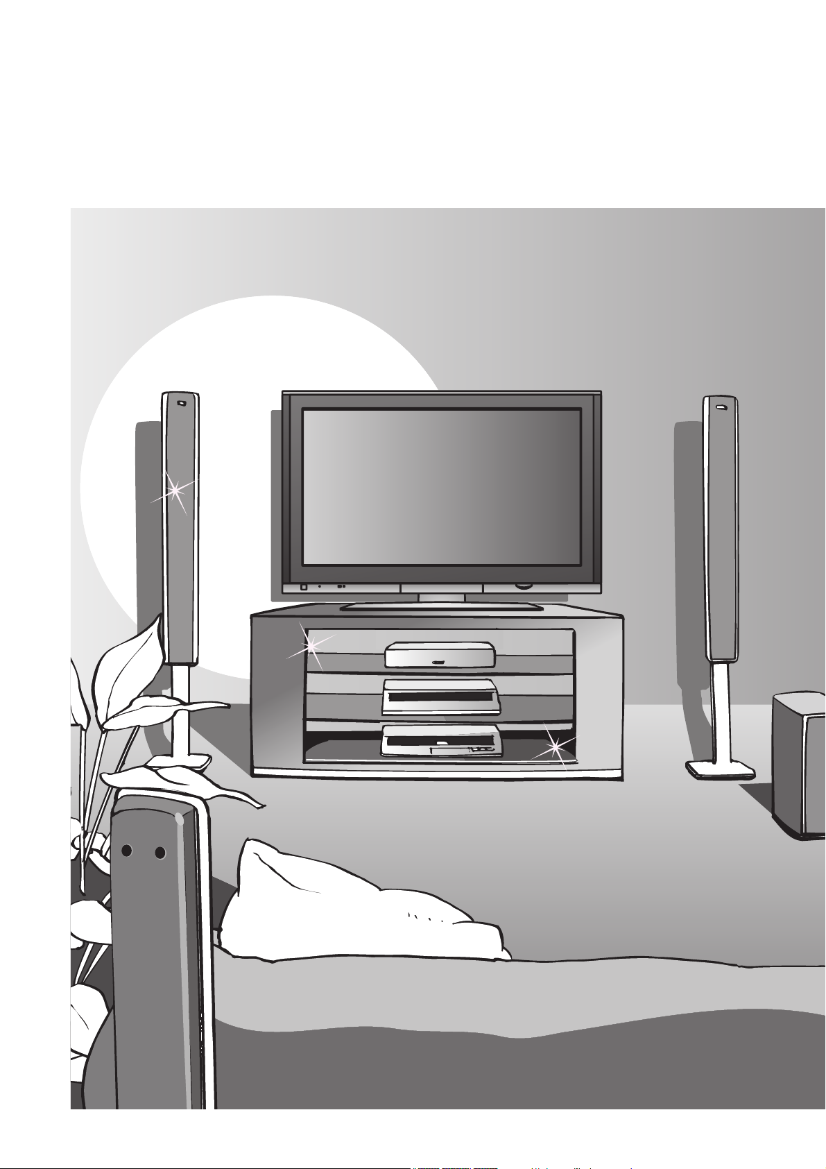
Turn your own living room into a movie theatre!
Experience an amazing level of multi-
2
Page 3
media excitement
Enjoy rich multi-media
Contents
Be Sure to Read
Safety Precautions ······································ 4
•
(Warning / Caution)
Notes ··························································· 5
•
Maintenance ··············································· 5
•
Amplifi er with
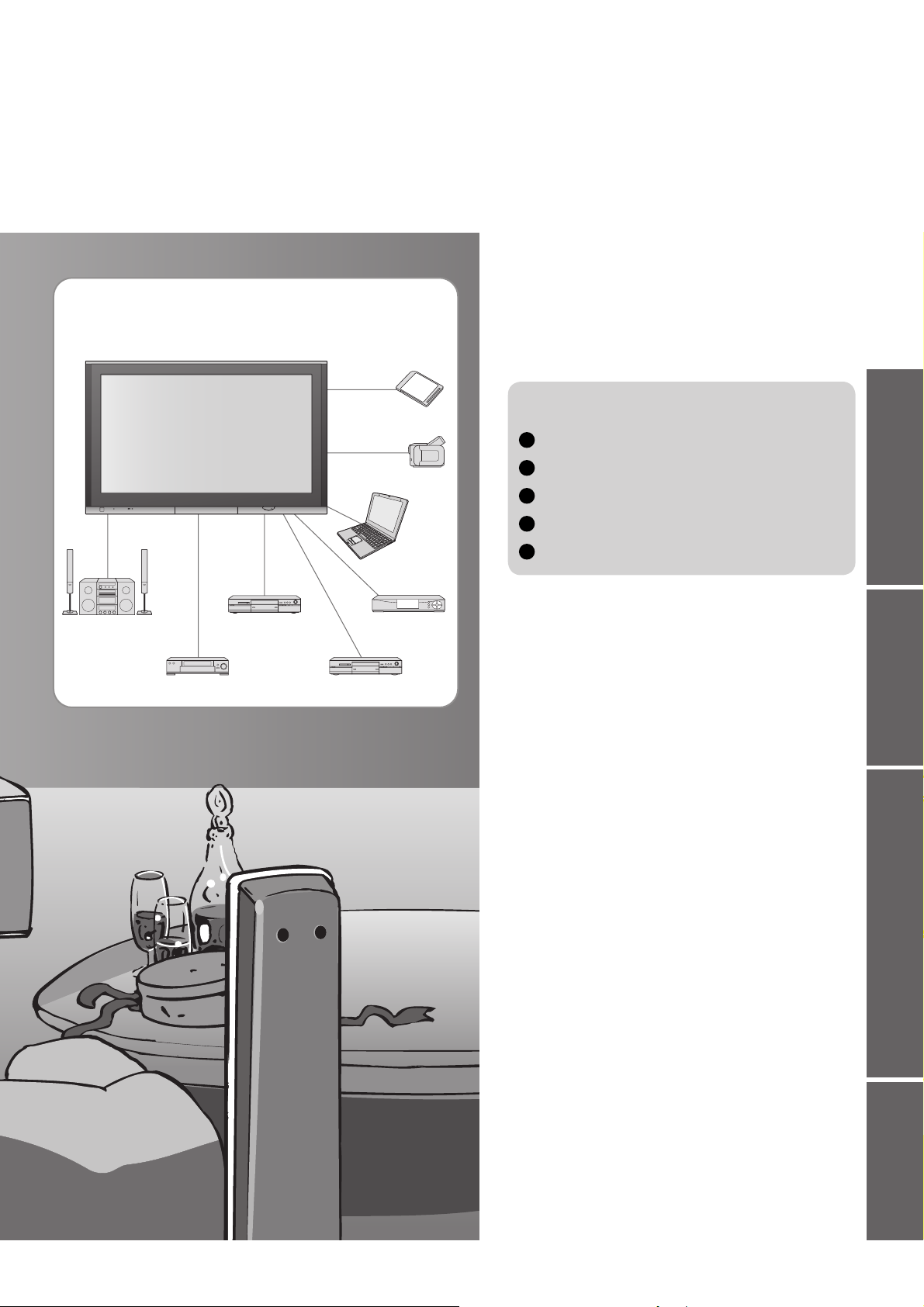
Speaker system
VCR
DVD Recorder
SD memory card
Camcorder
Set top box
DVD player
Personal
computer
Quick Start Guide
Accessories / Options
Identifying Controls
Basic Connection
Auto Tuning
Language Setting
Enjoy your TV!
Basic Features
Watching TV ·············································· 12
•
Watching Videos and DVDs ······················ 14
•
Viewing Teletext ········································16
······························· 9
··················· 8
·········· 6
··············· 7
················· 10
•
Advanced Features
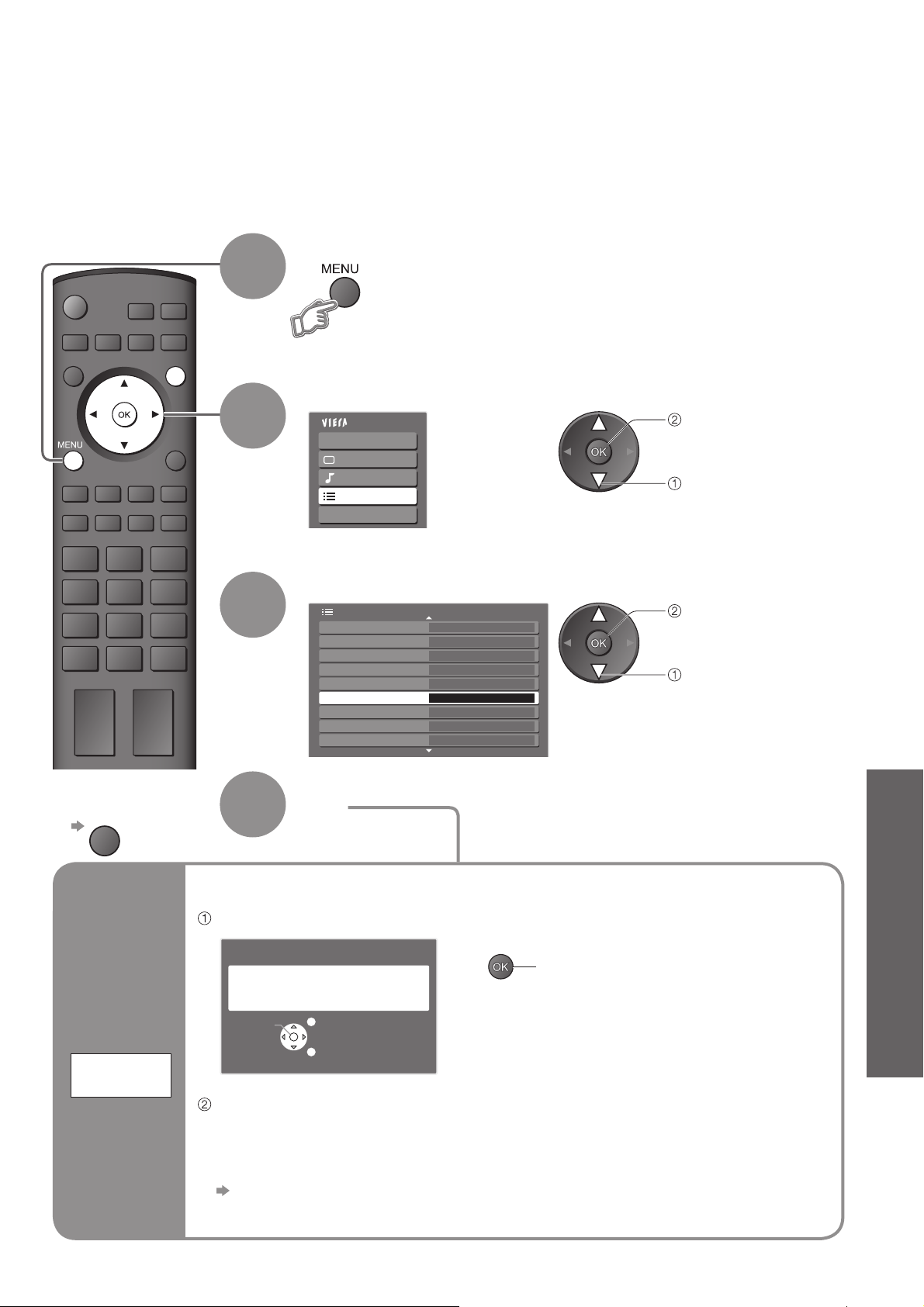
How to Use Menu Functions ····················· 18
•
(picture, sound quality, etc.)
Editing and Setting Channels ···················· 22
•
Control Channel Audience ························ 24
•
Restore Settings ······································ 25
•
Input Labels ·············································· 26
•
Displaying PC Screen on TV ·····················27
•
Viewing from card (Photos) ······················· 28
•
VIERA Link “HDAVI ControlTM” ···················30
•
External Equipment ··································· 32
•
Viewing Advanced FAQs, etc.Quick Start Guide
FAQs, etc.
Technical Information ································34
•
FAQs ·························································39
•
Licence ······················································ 41
•
Specifi cations ············································ 42
•
3
Page 4

Safety Precautions
Warning
Handling the mains plug and lead
Insert the mains plug fully into the socket outlet. (If the mains plug is loose, it could generate heat and cause fi re.)
Ensure that the mains plug is easily accessible.
Ensure the grounding pin on the mains plug is securely connected to prevent electrical shock.
Do not touch the mains plug with a wet hand. (This may cause electrical shock.)
Do not use any mains lead other than that provided with this TV. (This may cause fi re or electrical shock.)
Do not damage the mains lead. (A damaged lead may cause fi re or electrical shock.)
Do not move the TV with the lead plugged in the socket outlet.
Do not place a heavy object on the lead or place the lead near a high-temperature object.
Do not twist the lead, bend it excessively, or stretch it.
Do not pull on the lead. Hold onto the mains plug body when disconnecting lead.
Do not use a damaged mains plug or socket outlet.
If you fi nd any
abnormality,
remove the
mains plug immediately!
AC 220-240 V
50 / 60 Hz
Do not remove covers
NEVER modify the TV yourself
(High-voltage components may cause serious
electrical shock.)
Have the TV checked, adjusted, or repaired at your
local Panasonic dealer.
Keep liquids away from the TV
To prevent damage which may result in fi re or
shock hazard, do not expose this appliance to
dripping or splashing.
Do not place containers with water (fl ower vase,
cups, cosmetics, etc.) above the TV. (including on
shelves above, etc.)
Do not place foreign objects
inside the TV
Do not let metal or fl ammable objects drop into the
TV through the air vents (fi re or electrical shock
may result).
Do not place the TV on sloped
or unstable surfaces
The TV may fall off or tip over.
Use only the dedicated stands
/ mounting equipment
Using an unauthorized stand or other fi xtures may
make the TV shaky, risking injury. Be sure to ask
your local Panasonic dealer to perform setup.
Use optional stands / mounts (p. 6).
4
Do not expose to direct sunlight
and other sources of heat
Avoid exposing the TV to direct sunlight and other
sources of heat. To prevent fi re never place any
type of candle or naked fl ame on top or near the TV.
Do not allow children to
handle SD card
As with a small object, SD card can be swallowed
by young children. Please remove SD card
immediately after use.
Page 5
Notes
Caution
This appliance is intended for use
in tropical climates
When cleaning the TV, remove the
mains plug
(Cleaning an energized TV may cause electrical shock.)
When TV will not be used for a
long time, remove the mains plug
This TV will still consume some power even
in the Off mode, as long as the mains plug is
still connected to a live socket outlet.
Transport only in upright position
Transporting the TV with its display panel
facing upright or downward may cause
damage to the internal circuitry.
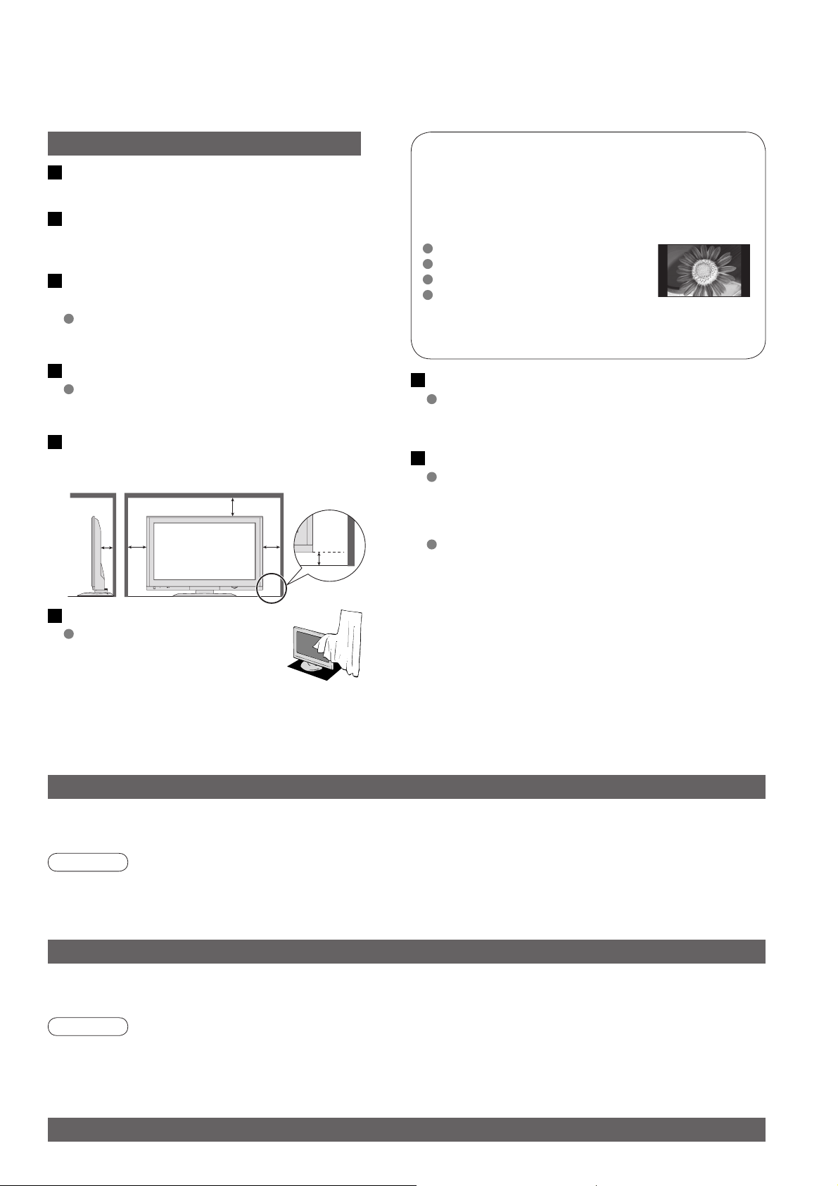
Allow suffi cient space around the
TV for radiated heat
Minimum distance
10
10
7
(cm)
10
4.5
Do not display a still picture for a long time
This causes the image to remain on the plasma
screen (“image retention”).
This is not considered a malfunction and is not
covered by the warranty.
Typical still images
Channel number and other logos
Image displayed in 4:3 mode
Video game
Computer image
To prevent image retention, contrast is lowered
automatically after a few minutes if no signals are
sent or no operations are performed. (p. 39)
Auto power standby function
If no signal is received and no operation is
performed in TV mode for 30 minutes, the TV will
automatically go to standby mode.
Keep the TV away from these equipment
Electronic equipment
In particular, do not place video equipment near the
TV (electromagnetic interference may distort images
/ sound).
Equipment with an infrared sensor
This TV also emits infrared rays (this may affect
operation of other equipment).
Do not block the rear air vents
Blocked ventilation by curtains,
etc. may cause overheating, fi re
or electrical shock.
Maintenance
First, remove the mains plug from the socket outlet.
Display panel
Regular care: Gently wipe the surface clean of dirt by using a soft cloth.
Major contamination: Wipe the surface clean using a soft cloth dampened with clean water or diluted neutral
detergent by 100 times of water. Then, using a soft dry cloth, evenly wipe the surface clean until it is dry.
Caution
The surface of the display panel has been specially treated and may be easily damaged.
•
Do not tap or scratch the surface with your fi ngernail or other hard object.
Use care not to subject the surface to bug repellent, solvent, thinner, or other volatile substances
•
(this may degrade surface quality).
Cabinet
Regular care: Wipe the surface clean using a soft dry cloth.
Major contamination: Dampen a soft cloth with clean water or water containing a small amount of neutral detergent.
Then, wring the cloth and wipe the surface clean with it. Finally, wipe the surface clean with a dry cloth.
Caution
Use care not to subject the TV's surfaces to detergent.
•
(A liquid inside the TV could lead to product failure.)
Use care not to subject surfaces to bug repellent, solvent, thinner, or other volatile substances
•
(this may deteriorate the surface by peeling the paint).
Do not allow the cabinet to make contact with a rubber or PVC substance for a long time.
•
Mains plug
Wipe the mains plug with a dry cloth at regular intervals. (Moisture and dust may lead to fi re or electrical shock.)
5
Page 6
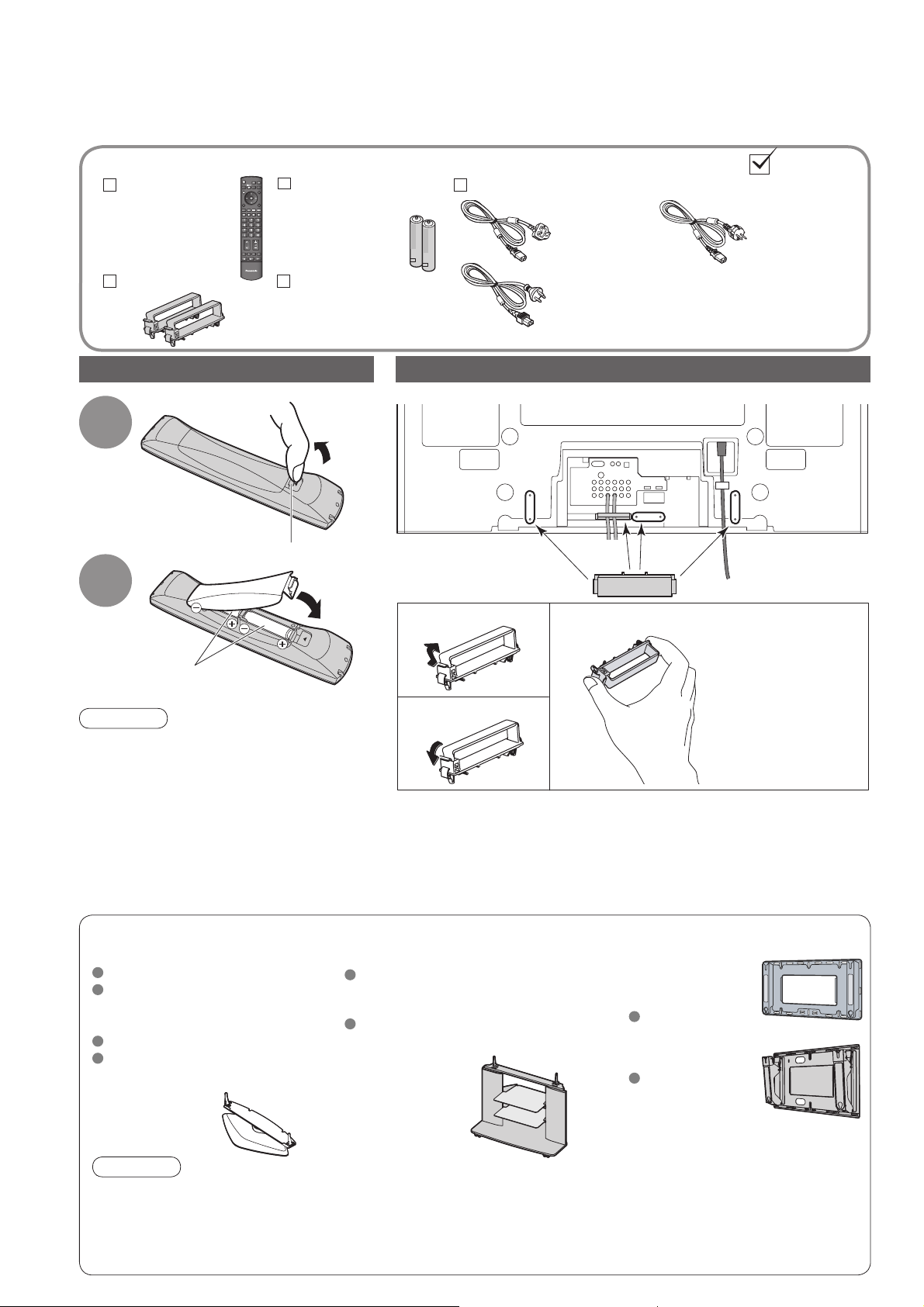
Accessories / Options
Standard accessories
Remote
Control
Transmitter
N2QAYB000120
•
Clamper (2)
TV
Check that you have the accessories and items shown
Batteries for the
Remote Control
Transmitter
R6 (AA)
•
Operating Instructions
Installing remote’s batteries
Pull
1
Hook
open
Close
2
(2)
Rear of the TV
Snap open
Mains Lead
Using the clamper
( TH-42PV700H,
TH-42PV700M,
TH-50PV700H,
TH-50PV700M)
( TH-42PV700MT)
Remove from the TV
( TH-42PV700M,
TH-42PV700MR,
TH-50PV700M,
TH-50PV700MR)
Note the correct
polarity (+ or -)
Caution
Incorrect installation may cause battery
•
leakage and corrosion, resulting in
damage to the remote control.
Do not mix old and new batteries.
•
Do not mix different battery types (such
•
as alkaline and manganese batteries).
Do not use rechargeable (Ni-Cd)
•
batteries.
Do not burn or breakup batteries.
•
Optional accessories
Pedestal
TY-ST42P600W
TY-ST42D2-WS
( TH-42PV700H, TH-42PV700M,
TH-42PV700MR, TH-42PV700MT)
TY-ST50P600W
TY-ST50D2-WS
( TH-50PV700H, TH-50PV700M,
TH-50PV700MR)
Snap shut
Do not bundle the RF cable and mains lead together (could cause
•
distorted image).
Fix cables with clampers as necessary.
•
When using the optional accessory, follow the option’s assembly
•
manual to fi x cables.
Plasma TV stand Wall-hanging
TY-S42PX700W
( TH-42PV700H, TH-42PV700M,
TH-42PV700MR, TH-42PV700MT)
TY-S50PX700W
( TH-50PV700H, TH-50PV700M,
TH-50PV700MR)
bracket
(vertical)
TY-WK42PV3W
(angle)
TY-WK42PR3W
Push both side
hooks and pull
out
6
Caution
In order to maintain the unit’s performance and safety, be absolutely sure to ask your dealer or a licenced
•
contractor to secure the wall-hanging brackets.
Carefully read the instructions accompanying the plasma TV stand or pedestal, and be absolutely sure to take
•
steps to prevent the TV from tipping over.
Handle the TV carefully during installation since subjecting it to impact or other forces may cause product damage.
•
Page 7
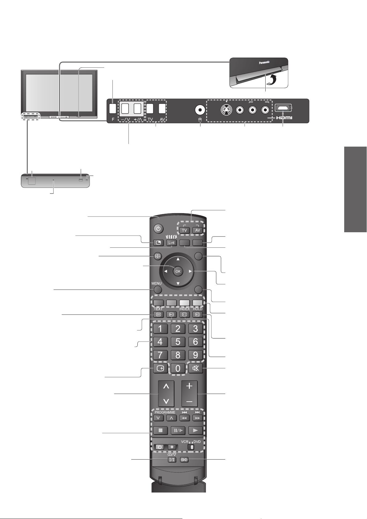
PU
LL
Identifying Controls
SD CARD slot (p. 28)
Function select
Volume / Contrast / Brightness / Colour /
•
Sharpness / Tint (NTSC mode) / Bass /
Treble / Balance / Auto Tuning (p. 23)
AV4 IN
S VIDEO
VIDEO L/MONO-R AV IN
Lift door to open
AUDIO
Changes the
input mode
Increases or decreases the programme position by one. When a function is already displayed,
press to increase or decrease the selected function. When in Standby mode, switches TV On.
Mains power
On / Off switch
Power LED
Standby: red
•
On: green
Standby On / Off switch
(Switches TV On or Off standby)
Multi window (p. 13)
Access VIERA Link Menu (p. 31)
Changes aspect ratio (p. 13)
OK button to confi rm selections and choices
Press after selecting programme positions to
quickly change programme.
Main Menu
Press to access VIERA Link, Picture, Sound,
Setup menus and Language (p. 10 and p. 18)
Teletext (p. 16)
Viewing a favourite teletext channel (p. 17)
Programme / channel change buttons (0-9)
and Teletext page buttons.
When in Standby mode, switches TV On.
Programme Information (p. 13)
Remote control signal receiver
C.A.T.S. (Contrast Automatic Tracking System) sensor
( senses brightness to adjust picture quality in “Auto” Mode in Picture Menu) (p. 20)
(p. 12 and p. 16)
Headphones jack
(p. 32)
POWER
MULTI PIP
ASPECT
RECALL MUTE
INPUT
OPTION
GRYB
F.P.
SD CARD
EXIT
RETURN
AV4 terminals
(p. 32)
Changes the input mode
TV -
changes TV mode
AV - changes AV input mode (p. 14)
Viewing SD Card (p. 28)
Option menu
Sets the preferred settings of viewing
and sound options easily (p. 12)
EXIT (Returns to TV screen)
Cursor buttons to make selections and
adjustments
Returns to the previous menu
Coloured buttons used for the
selection, navigation and operation of
various functions
Still picture
Teletext Hold (p. 17)
Teletext Index (p. 17)
Sound mute On / Off
(p. 12)
HDMI3 terminal
(p. 32)
(p. 14)
Quick Start Guide
•
•
Identifying Controls
Accessories / Options
Selects programmes in sequence
VCR / DVD operations
Stereo / Bilingual Sound Selection (p. 36)
(p. 15)
CH VOL
REC
POWER
Volume
SURROUND
Surround (p. 20)
7
Page 8
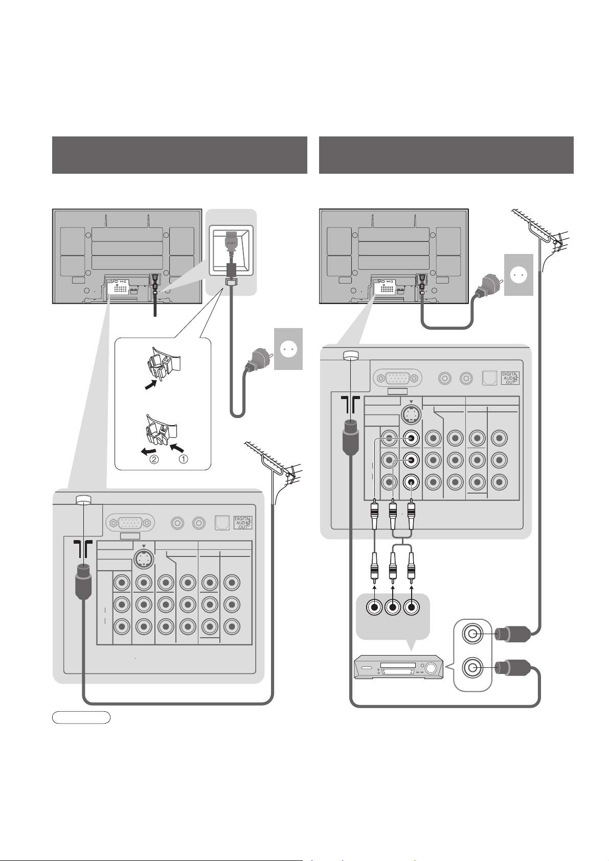
Basic Connection
External equipment and cables shown are not supplied with this TV.
Please ensure that the unit is disconnected from the mains socket before attaching or disconnecting any leads.
When disconnecting the mains lead, be absolutely sure to disconnect the mains plug at the socket outlet fi rst.
Example 1
Connecting aerial
Example 2
Connecting DVD Recorder / VCR
TV only TV, DVD Recorder or VCR
AC 220-240 V
Clamper
To unfasten
•
AUDIO
IN
L
R
50 / 60 Hz
Mains lead
(supplied)
Aerial
AV1 IN
MONITOR
OUT
VIDEO
L
AUDIO
R
S VIDEO
Mains lead (supplied)
R
PC
AV2 IN AV3 IN
COMPONENT
PB/C
PR/C
AC 220-240 V
50 / 60 Hz
AUDIO
IN
L
VIDEO COMPONENT
Y
B
MONOMONOMONO
L
R
R
AUDIO
PB/C
PR/C
AerialRear of the TV Rear of the TV
Y
B
R
8
PC
AV1 IN
MONITOR
OUT
VIDEO
L
AUDIO
R
S VIDEO
AV2 IN AV3 IN
COMPONENT
PB/C
PR/C
Y
B
R
VIDEO COMPONENT
Y
PB/C
MONOMONOMONO
L
PR/C
R
AUDIO
RF cable
B
R
DVD Recorder or VCR
VIDEO
OUT
AUDIO
OUT
RF OUT
RF cable
RF IN
RF cable
Note
Do not put the Coaxial cable close to the mains lead to avoid noise.
•
Do not place the Coaxial cable under the TV.
•
To obtain optimum quality picture and sound, an Aerial, the correct cable (75 Ω coaxial) and the correct
•
terminating plug are required.
If a communal Aerial system is used, you may require the correct connection cable and plug between the wall
•
Aerial socket and the TV.
Your local Television Service Centre or dealer may be able to assist you in obtaining the correct Aerial system for
•
your particular area and the accessories required.
Any matters regarding Aerial installation, upgrading of existing systems or accessories required, and the costs
•
incurred, are the responsibility of you, the Customer.
Page 9
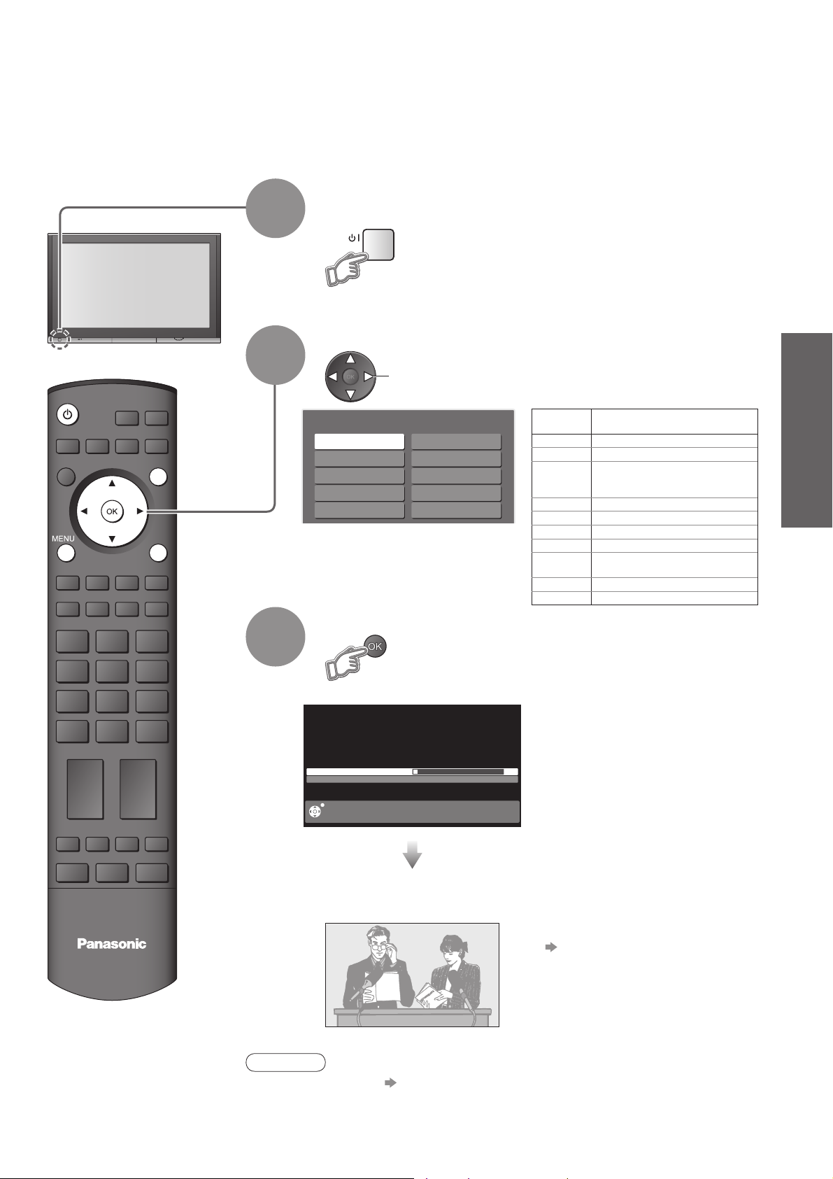
Auto Tuning
Search and store TV channels automatically.
These steps are not necessary if the setup has been completed by your local dealer.
Plug the TV into mains socket and switch On
(Takes a few seconds to be displayed)
1
You can now use the remote
•
control to turn On the TV or turn
the TV to standby mode.
(Power LED: On)
POWER
INPUT
OPTION
SD CARD
EXIT
RETURN
2
3
Select your system
select
System Selection
China
HK/UK
Asia/M.East
NZ/INDONES
Australia
E.Europe
SPECL Ver
America
CATV
Japan
Start Auto Tuning
3
CH 4
Scan 1 120
PLEASE WAIT
EXIT
System
Selection
China China
HK/UK Hong Kong, United Kingdom
Asia/M.East
NZ/INDONES
Australia Australia
E.Europe CIS, Poland, etc.
SPECL Ver South Africa
America USA, Chile, Mexico, Panama, Peru,
CATV USA CATV
Japan Japan
Auto Tuning will start to search for
•
TV channels and store them.
The TV memorises the channels
tuned in order from programme
number 1.
The sorted programme order
depends upon the TV signal,
the broadcasting system and
reception conditions.
Malaysia, Singapore, Thailand, Asia
countries, Kuwait, Saudi Arabia, United
Arab Emirates, Middle East countries, etc.
New Zealand, Indonesia, etc.
Philippines, Taiwan, Venezuela, etc.
REGION
Quick Start Guide
•
•
Auto Tuning
Basic Connection
Auto Tuning is now complete and
your TV is ready for viewing.
To edit channels
•
TV
Note
If tuning have failed “Auto Tuning” (p. 23).
•
If you turned the TV Off during Standby mode last time, the TV will be in Standby
•
mode when you turn the TV On with Mains power On / Off switch.
Editing and Setting Channels
(p. 22)
9
Page 10
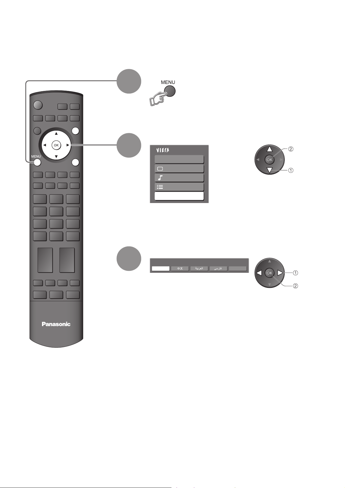
Language Setting
You can change language for on-screen displays.
Display the menu
1
POWER
MULTI PIP
ASPECT
RECALL MUTE
CH VOL
INPUT
OPTION
GRYB
F.P.
SD CARD
EXIT
RETURN
2
3
Select “Language”
Main Menu
VIERA Link
Picture
Sound
Setup
Language
Select the language
Language
English Français
Chinese
access
select
change
store
TV
10
Page 11
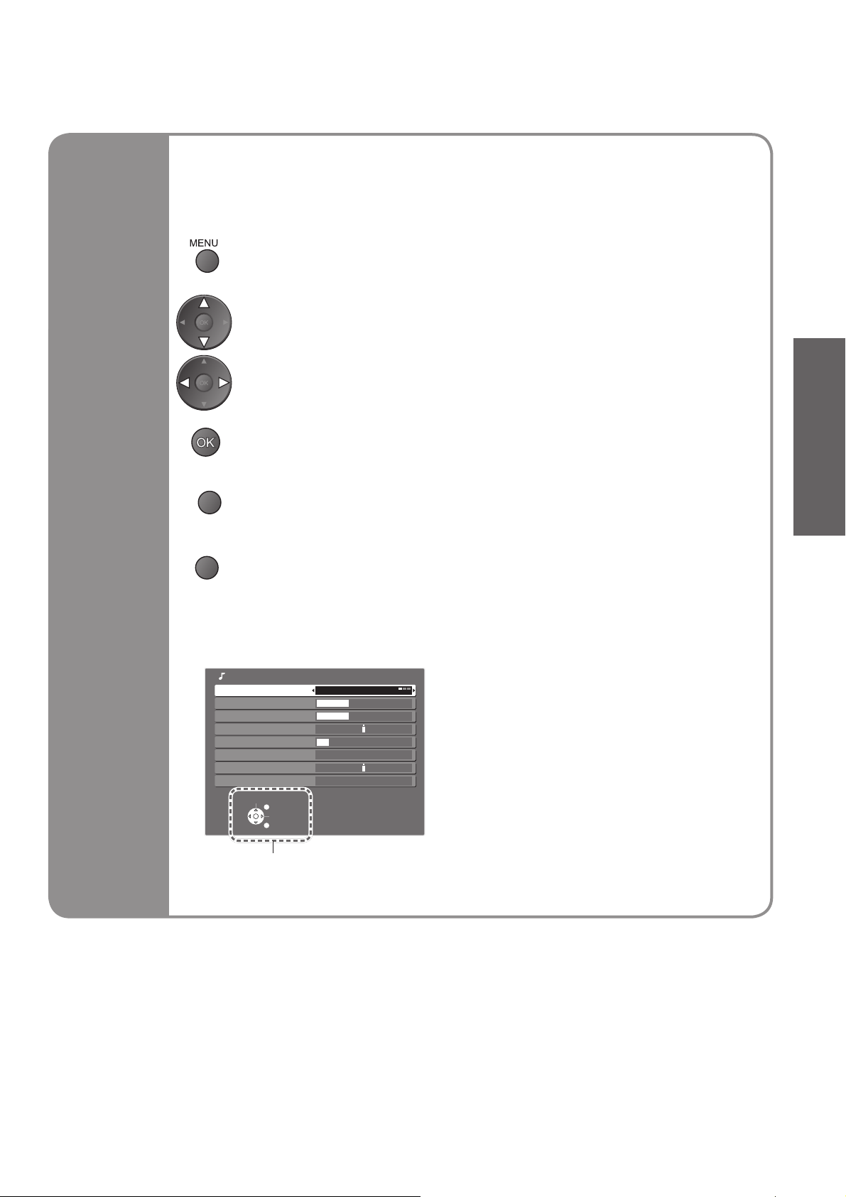
Many features available on this TV can be accessed via the On Screen Display
menu.
How to use remote control
■
Open the main menu
Move the cursor / select the menu
Move the cursor / adjust levels / select from a range of options
Access the menu / store settings after adjustments have been made or options
have been set
Quick Start Guide
Using the
On Screen
Displays
RETURN
Return to the previous menu
EXIT
ON SCREEN HELP Instructions box
■
Exit the menu system and return to the normal viewing screen
(example: Sound Menu)
Sound Menu
Menu Music
Bass
Treble
Balance
Headphone Volume
Surround Off
Volume Correction
Reset to Default Set
Select
EXIT
Change
RETURN
12
12
11
On-screen operation
guide will help you.
•
Language Setting
11
Page 12
Watching TV
O
Turn power on
POWER
POWER
MULTI PIP
INPUT
OPTION
1
SD CARD
Mains power On / Off switch should be On.
ASPECT
RECALL
CH VOL
EXIT
RETURN
GRYB
F.P.
MUTE
Volume
2
1 BBS
CH05 5.5MHz PAL Corontation Street
Bad Signal Encrypted
Information banner
STTL
AD TXT Stereo 45
Select a channel
up
CH
To select the two or three-digit programme number, e.g. 39
•
or
down
(in a short time)
POWER
REC
SURROUND
SURROUND
Other useful functions (Operate after )
■
Hold
Freeze / unfreeze picture
Check or change the current
programme status instantly
To change
Display the
current
programme
status
•
Teletext Language
Selects teletext language
Volume Correction
Adjusts volume of individual channel or input mode
Note
Also possible to change the settings in Menu list (p. 20 and p. 21).
•
PTION
change
select
12
Page 13
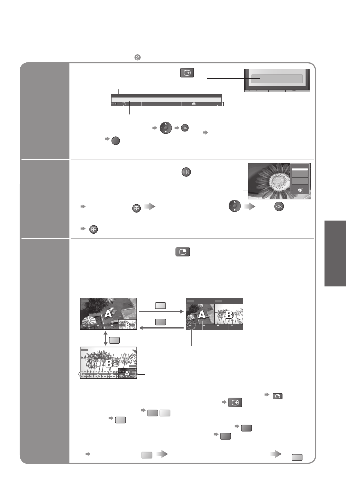
Other useful functions (Operate after )
A
A
A
■
Display programme information
Channel
1 BBS
CH05 5.5MHz PAL Corontation Street
Display
information
banner
Sound mute
Stereo sound
To select another channel
•
To hide
•
Bad Signal Encrypted
Sound system
EXIT
Colour system
RECALL
STTL
AD TXT Stereo
Teletext
Programme
To set display timeout
•
Appears also when changing channel.
•
Programme information is referred to
•
teletext signal.
45
Features available
Off timer
“Banner Display Timeout” (p. 21)
Change
aspect
ratio
Change the aspect ratio (p. 35)
SPECT
Enjoy viewing the picture at its optimum size and aspect.
Aspect Selection list
To change the mode
•
Display Aspect
Selection list
To change the mode using the ASPECT button only
•
SPECT
(Press repeatedly until you reach the desired mode)
SPECT
During the list is displayed,
select the mode
MULTI PIP
Store
Aspect Selection
16:9
Just
4:3
4:3 Full
Zoom1
Zoom2
Zoom3
Select
Change
View in multi window (p. 36)
TH-42PV700MR, TH-50PV700MR (one tuner model)
Enjoy viewing two images at once, such as a TV programme and a DVD.
Other model (two tuners model)
Enjoy viewing two images at once, such as a TV program and a DVD, or one TV program
and another TV program.
Picture-in-Picture mode (PIP)
TV
DVD
Exit PAP Change
Y
G
Picture-and-Picture mode (PAP)
DVDTV
Exit PIP Change
EXIT
RETURN
Viewing
•
Watching TV
B
Watch TV,
DVD
DVD, etc.
in multi
window
Exit PAP Change
Operations in multi window
To exit multi window (return to the single-screen view with main screen)
•
To change the layout, images, fi rst show the colour bar
•
To change the layout G
To swap
To exit multi window (TH-42PV700MR, TH-50PV700MR only)
To change the sub screen’s channel (Other model)
To change the input mode or position of sub screen
Swap sub screen
for main screen
TV
Colour bar
Y
B
B
Change the input mode or position
by the remote control (p. 12 or p. 14)
Main screen
Exit: ( TH-42PV700MR, TH-50PV700MR only)
Focus: ( Other model)
Remote control operations
•
apply to the main screen.
Sub screen
MULTI PIP
RECALL
R
R
Swap again
B
13
Page 14
Watching Videos and DVDs
Connect the external equipment (VCRs, DVD equipment, etc.) and you can watch the input.
To connect the equipment (p. 8)
The Remote Control is capable of operating some functions of selected Panasonic external equipment.
POWER
MULTI PIP
ASPECT
RECALL MUTE
CH
INPUT
OPTION
GRYB
F.P.
VOL
SD CARD
EXIT
RETURN
1
2
3
Display the Input select menu
Select the input mode connected to the equipment
Input Selection
AV1
AV2
AV3
AV4
PC
HDMI1
HDMI2
HDMI3
TV
You can also select the input using the AV button on the remote
•
control or the front panel of the TV.
Press the button repeatedly until the desired input is selected.
You can label or skip each input modes “Input Labels” (p. 26)
•
watch
select
View
Displays the selected mode
REC
POWER
SURROUND
To return to TV
■
Note
If the external equipment has an aspect adjustment function, set to “16:9”.
•
For details, see the manual of the equipment or ask your local dealer.
•
14
Page 15

Panasonic equipment connected to the TV can be directly operated with the remote control.
POWER
VCR / DVD switch
Select VCR to operate Panasonic VCR or DVD equipment
Select DVD to operate Panasonic DVD equipment or Player home theatre
Standby
Set to Standby mode / Turn on
Play
Playback videocassette / DVD
Stop
Stop the operations
Rewind / Skip / Search
VCR: Rewind, view the picture rapidly in reverse
DVD: Skip to the previous track or title
Press and hold to search backward
Fast-forward / Skip / Search
VCR: Fast-forward, view the picture rapidly forward
DVD: Skip to the next track or title
Press and hold to search forward
∗
Viewing
Pause
Pause / Restart
DVD: Press and hold to play at slow speed
Programme Up / Down
Select programme
Record
Start recording
Setting your remote control to operate Panasonic VCR, DVD, etc.
∗
Set the VCR / DVD switch to the appropriate position
Press and hold
Enter the appropriate code for the equipment
to be controlled, see table below
“VCR” position
Equipment Code
VCR 10 (default)
DVD 11
Note
Confi rm correct operation after the code changed.
•
“DVD” means DVD player, DVD recorders and Recorder home theatre.
•
Some operations may not be possible on some equipment models.
•
POWER
during the following operations
“DVD” position
Equipment Code
Player home theatre
Press
DVD 70 (default)
71
•
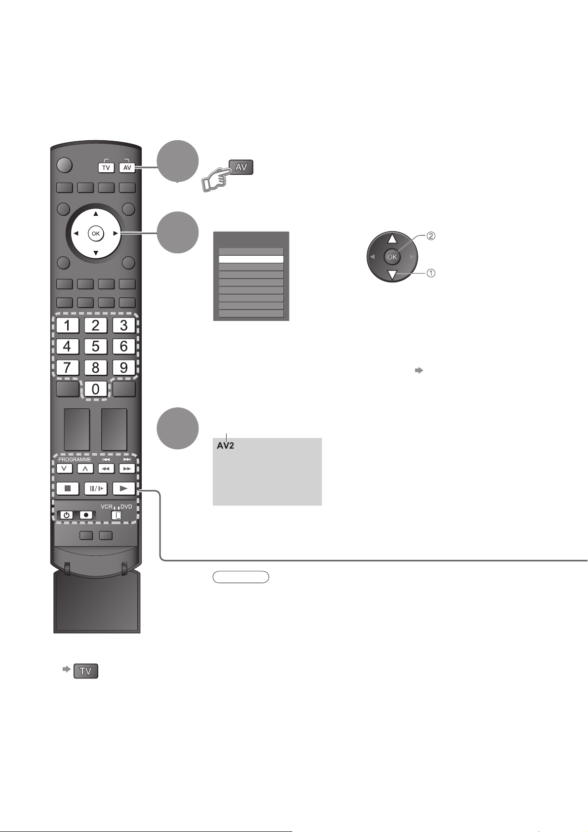
Watching Videos and DVDs
15
Page 16

Viewing Teletext
You can enjoy teletext broadcasting, including news, weather forecasts and subtitles, if this service is
provided by the broadcasters.
What is FASTEXT mode?
In FASTEXT mode, four differently coloured subjects are situated at the bottom of the screen. To access more
information about one of these subjects, press the appropriately coloured button. This facility enables fast access to
information on the subjects shown.
What is List mode?
In List mode, four differently coloured page numbers are situated at the bottom of the screen. Each of these
numbers can be altered and stored in the TV’s memory. (“Store frequently viewed pages”, p. 17)
To change mode “Teletext” in Setup Menu (p. 21)
■
POWER
MULTI PIP
ASPECT
INPUT
OPTION
SD CARD
EXIT
RETURN
1
Switch to Teletext
Displays Index
•
(content varies
depending on the
broadcasters)
Current
page
number
Sub page number
<< 01 02 03 04 05 06 07 >>
17:51 28 Feb
TELETEXT
INFORMATION
Colour bar
Time / date
GRYB
F.P.
RECALL MUTE
CH VOL
2
Select the page
or
To adjust contrast
■
To return to TV
■
up
down
G
or
R
(Corresponds to the colour bar)
As the blue bar is displayed
B
Y
16
Using teletext conveniently
■
Reveal
Reveal hidden words e.g. quiz page answers
hidden
data
FULL /
TOP /
BOTTOM
R
G
Re-hide
•
(Expand the TOP half)
R
(TOP)
Normal (FULL)(BOTTOM)
(Expand the BOTTOM half)
Page 17

HOLD
INDEX
If you wish to hold the current page without updating
Stop or resume automatic updating
To resume
■
Return to the main index page
Call up a
favourite
pages
View in
multi
window
Store
frequently
viewed
pages
F. P.
Watch TV and Teletext in two windows at once
MULTI PIP
Store frequently viewed pages in the colour bar
As page is
displayed
To change stored pages
■
B
Colour button you
want to change
Call up the page stored in “blue”.
•
Factory setting is “P103”.
•
•
B
Corresponding
colour button
Enter new page number
Operations can be made only in Teletext screen.
press
and
hold
The number changes to white.
press
and
hold
(List mode only)
Viewing
•
Viewing Teletext
View sub
page
Watch
TV while
waiting
for update
View sub page (Only when teletext is more than one page)
Appears at upper-left
corner of the screen
To view specifi c sub page
■
Sub pages:
•
The number of sub pages varies depending on the broadcasters (up to 79 pages).
It may take some time for searching, during which time you can watch TV.
View the TV picture while searching for a teletext page
Teletext automatically updates itself when new information becomes available.
The news page provides a function that indicates arrival of latest news (“News Flash”).
•
B
Changes to TV screen temporarily
P108
Y Y
(You cannot change the channel.)
Enter the
4-digit number
example: P6
Appears
when
updating is
completed
View the
updated
page
17
Page 18
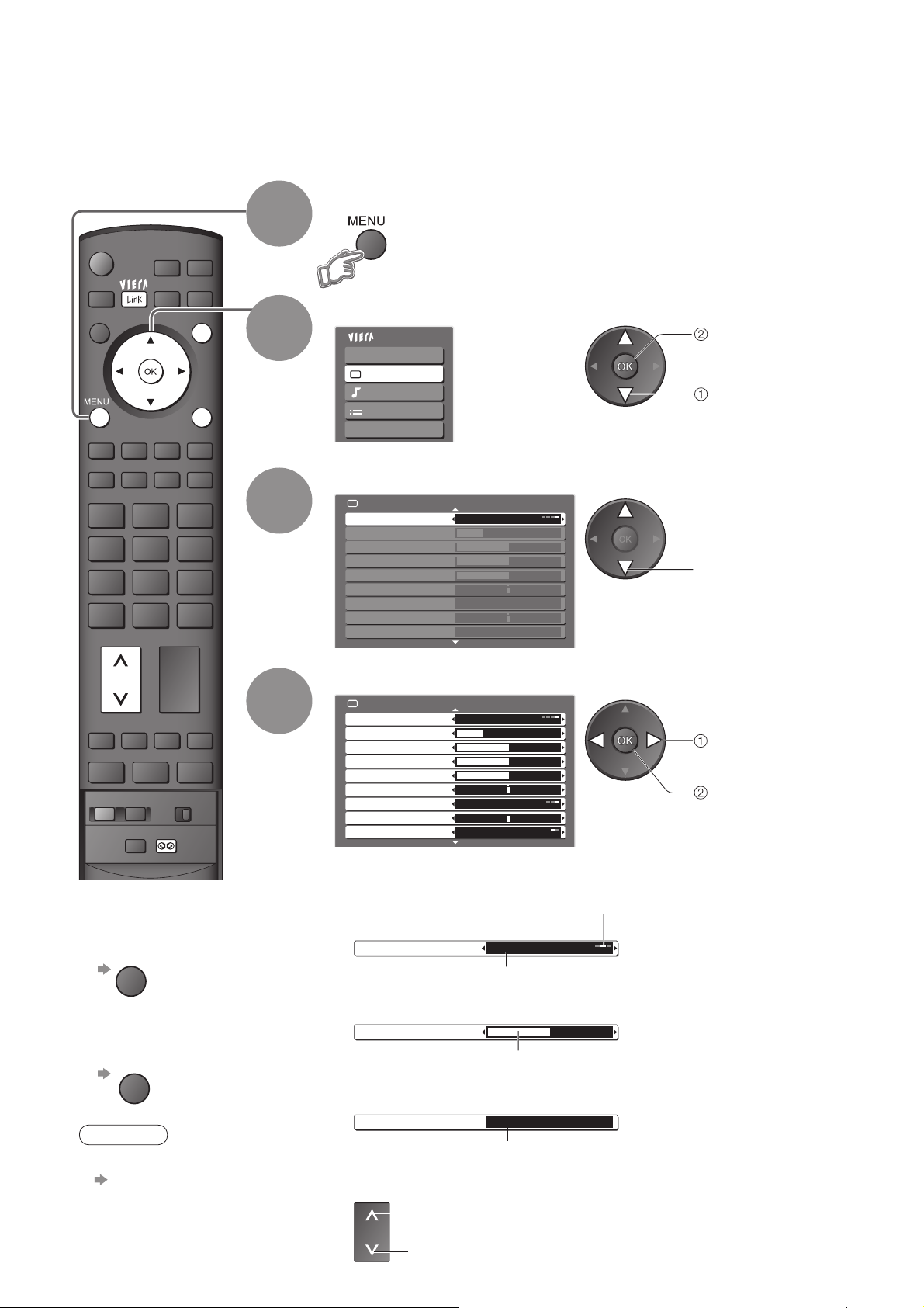
How to Use Menu Functions
Various menus allow you to make settings for the picture, sound, and other functions.
Display the menu
POWER
MULTI PIP
ASPECT
RECALL MUTE
CH
POWER
INPUT
OPTION
GRYB
F.P.
VOL
REC
SURROUND
SD CARD
EXIT
RETURN
1
2
3
4
Displays the functions that can be set
•
(varies according to the input signal)
Select the menu
Main Menu
VIERA Link
Picture
Sound
Setup
Language
(example: Picture Menu)
Select the item
Picture Menu 1/2
Menu Auto
Contrast
Brightness
Colour
Sharpness
Tint
Colour Temperature Warm
CH Colour Set
Colour Management Off
(example: Picture Menu)
Adjust or select
Picture Menu
Menu Auto
Contrast
Brightness
Colour
Sharpness
Tint
Colour Temperature Warm
CH Colour Set
Colour Management Off
(example: Picture Menu)
access
select
30
50
50
50
1/2
30
50
50
50
select
change
store or access
(Required by some
functions)
18
To return to TV
■
at any time
EXIT
To return to the
■
previous screen
RETURN
Note
To initialize all settings
•
“Shipping Condition”
(p. 25)
Choose from among alternatives
■
Number and positions
of alternatives
Colour Temperature Standard
Changed
Adjust using the slide bar
■
Sharpness
Moved
Go to the next screen
■
Tuning Menu Access
Displays the next screen
To change menu pages
■
up
CH
down
Page 19
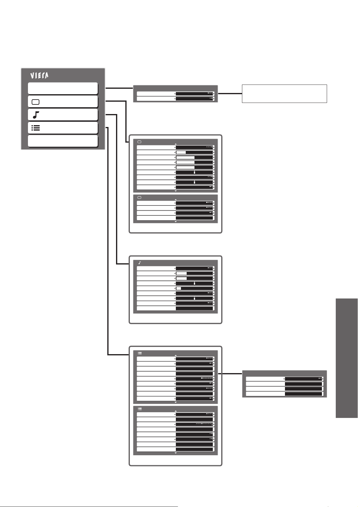
Overview
■
Main Menu
VIERA Link
Picture
Sound
Setup
Language
VIERA Link Menu
VIERA Link Control
Speaker Selection
Picture Menu
Menu Auto
Contrast
Brightness
Colour
Sharpness
Tint
Colour Temperature Warm
CH Colour Set
Colour Management Off
Picture Menu
P-NR Off
MPEG NR Off
3D-COMB Off
Reset to Default Set
Recorder
Home Cinema
(p. 31)
1/2
30
50
50
50
2/2
(p. 20)
The menu of the accessed
equipment
•
How to Use Menu Functions
(picture, sound quality, etc.)
Sound Menu
Menu Music
Bass
Treble
Balance
Headphone Volume
Surround Off
Volume Correction
HDMI1 Input Auto
Reset to Default Set
Setup Menu
AV Colour System Auto
Colour Matrix SD
Child Lock Access
Tuning Menu
Off Timer Off
Teletext FASTEXT
Teletext Language English
Shipping Condition Access
Power Save Off
Setup Menu
Side Panel Off
Input Labels
Banner Display Timeout
VIERA Link Settings
SD Card LED
Refresh Rate
Software Licence Access
System Information Access
Access
Access
3 seconds
Access
On
100Hz
12
12
11
(p. 20)
1/2
2/2
Tuning Menu
Channel Selection
Auto Tuning Access
Programme Edit Access
Manual Tuning Access
Position
Access
Advanced
(p. 22)
Only available items can be selected.
•
(p. 21)
19
Page 20

How to Use Menu Functions
Menu list
■
Menu
VIERA Link
Picture
Item Adjustments / Confi gurations (alternatives)
VIERA Link Control
Speaker Selection
Menu
Contrast, Brightness,
Colour, Sharpness
Tint
Colour Temperature
CH Colour Set
Colour Management
P-NR
MPEG NR
Controls the connected Panasonic equipment
“Easy control only with VIERA remote control” (p. 31)
“Speaker control” (p. 31)
You can also access VIERA Link Menu directly using the VIERA Link button on the
•
remote control.
Basic picture mode (Dynamic / Standard / Cinema / Auto)
Set for each input signal
•
Adjusts colour, brightness, etc. for each picture mode to suit your taste
Adjusts tint of image
For NTSC signal reception only
•
Chooses the colour balance of the entire image (Cool / Standard / Warm)
Colour density varying between broadcast channels can be adjusted to three levels for
each reception channel
Select the channel you want to adjust and set this function
•
Automatically adjusts colours to vivid ones (Off / On)
Not valid on PC signal
•
Picture Noise Reduction
Automatically reduces unwanted picture noise (Off / Weak / Strong / Auto)
Not valid on HDMI or PC signal
•
Automatically reduces noise for watching DTV, DVD, VCD and SD Card
(Off / Weak / Mid / Strong)
3D-COMB
Reset to Default
Menu
Bass
Treble
Balance
Headphone Volume
Sound
Surround
Volume Correction
HDMI1/3 Input
Reset to Default
Automatically makes still pictures and slow pictures look more vivid (Off / On)
For PAL or NTSC signal reception only
•
Not valid on S-Video, components, PC, HDMI and SD Card
•
Press the OK button to reset the present Picture Menu to the default settings
Basic sound mode (Music / News / Cinema)
Set for each input signal
•
Adjusts the output level of deep bass
Adjusts the output level of high-pitch, shrill sound
Adjusts volume level of right and left speakers
Adjusts the volume of the headphones
Surround sound settings (Off / Simulated Surround / SRS TruSurround XT)
Simulated Surround
SRS TruSurround XT
Switching is also possible by the Surround button on the remote control (p. 7)
•
Adjusts volume of individual channel or input mode
Select to fi t the input signal (Auto / Digital / Analogue) (p. 37)
Auto : Automatic detection of digital or analogue sound source
Digital : HDMI cable connection
Analogue : HDMI-DVI adapter cable connection
HDMI input mode only
•
HDMI2 terminal is for digital signal only
•
No setting for HDMI2 available
•
Press the OK button to reset the present Sound Menu to the default settings
: Provides a dynamic enhancer to simulate improved spatial effects
:
SRS TruSurround XT® creates a high quality surround sound effect using just
two speakers from the source which can output surround encoded signals
20
Page 21

Menu list
■
Menu
Item Adjustments / Confi gurations (alternatives)
AV Colour System
Colour Matrix
Child Lock
Tuning Menu
Channel Selection
Auto Tuning
Programme Edit
Manual Tuning
Off Timer
Teletext
Selects optional colour system based on video signals in AV mode
(Auto / PAL / SECAM / NTSC4.43 / NTSC3.58)
Available only with 480p or 576p input signals in a natural colour from digital equipment
connected to AV2 / AV3 Component or HDMI1 / HDMI2 terminals
Select SD or HD to adjust suitable colour parameters for SD (standard defi nition) or HD
(high defi nition)
SD: Input signal is a normal TV system
•
HD: Input signal is a High-Defi nition system
•
Locks a programme channel to prevent access to it (p. 24)
Selects the most easily viewed channel selection method (Position / Direct) (p. 22)
Automatically sets the channels received in the area (p. 23)
Edits channels (p. 23)
Sets the channels manually (p. 22)
Sets the time the TV automatically turns Off (Off / 15 / 30 / 45 / 60 / 75 / 90 minutes)
Teletext display mode (FASTEXT / List) (p. 16)
•
How to Use Menu Functions
(picture, sound quality, etc.)
Teletext
Setup
Language
Shipping Condition
Power Save
Side Panel
Input Labels
Banner Display
Timeout
VIERA Link Settings
VIERA Link
Power off Link
Power on Link
SD Card LED
Refresh Rate
Selects teletext language (English / CIS / E.Europe / Persian)
Resets all settings, for example, when moving house (p. 25)
Reduces brightness of picture to economise on power consumption (Off / On)
Increases the brightness of the side panel (Off / Low / Mid / High)
The recommended setting is “High” to prevent panel “image retention”
•
Labels or skips each input terminals (p. 26)
Sets how long the information banner (p. 13) stays on screen
0 (No display) to 10 sec. in 1-sec. increments
•
Sets to use VIERA Link functions (Off / On) (p. 30)
Set to “Set” to use Power off Link function (No / Set) (p. 31)
Set to “Set” to use Power on Link function (No / Set) (p. 31)
Lights blue LED while SD Card is inserted (Off / On) (p. 29)
Changes the image processing of the panel (depending on the input signal) (50Hz / 100Hz)
Set to “100Hz” normally
•
Advanced
Software Licence
System Information
A different menu will be displayed while PC or SD Card is used. (p. 27 and p. 29)
•
Only available items can be selected.
•
Displays the software licence information
Displays the system information of this TV
21
Page 22

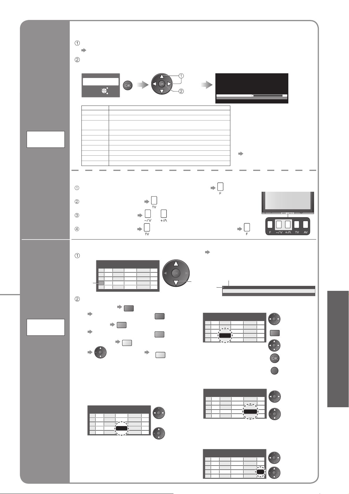
Editing and Setting Channels
The current channel settings can be changed according to your needs and reception conditions.
Display the menu
POWER
MULTI PIP
INPUT
OPTION
1
SD CARD
ASPECT
GRYB
F.P.
RECALL MUTE
CH
To return to TV
■
EXIT
VOL
EXIT
RETURN
2
3
4
Select “Setup”
Main Menu
VIERA Link
Picture
Sound
Setup
Language
Select “Tuning Menu”
Setup Menu
Child Lock
Tuning Menu
Off Timer Off
Teletext FASTEXT
Teletext Language
Shipping Condition
Power Save
Side Panel Off
Input Labels
Access
English
Off
Select a function
Tuning Menu
Channel Selection
Auto Tuning Access
Programme Edit Access
Manual Tuning Access
Position
Access
1/2
access
select
access
select
access
select
Channel Selection
Position
■
Example
Programme
Channel
Display
2
4
6
8
10
12
14
16
18
20
Received
Channel
Number
1
2
3
4
5
6
7
8
9
10
Set
channels
manually
Manual
Tuning
5
Set
■
Direct
Example
When Channel Selection is on
Position, and Auto Tuning is
2
performed, the TV memorises
4
6
the channels tuned in order
8
from Programme Number 1.
10
12
During Position mode various
14
reception channels can be
16
18
viewed.
20
Fine Tuning
■
Programme
Channel
Number
Display
1
2
3
4
5
6
7
8
9
10
–
2
–
4
–
6
–
8
–
10
Received
When Channel Selection is
Channel
on Direct, and Auto Tuning is
–
performed, the TV memorises
2
–
the Programme Number which is
4
the same as the channel tuned.
–
6
The Channel Display numbers
–
for the broadcast stations in
8
–
each region are listed on p. 34.
10
Use to make small adjustments to the tuning of an individual channel (affected by weather
conditions, etc.)
Manual Tuning
■
Set channel manually after Auto Tuning.
If a VCR is connected with only the RF cable, select programme position “0”.
Manual Tuning
Fine Tuning
Manual Tuning 1
Select the programme position
120
Search and storeSelect the channel
22
CH
search
store
Page 23
Automatically set the channels received in the area.
If a Child Lock PIN number (p. 24) has been set, it must be entered.
Select the channel selection method (Position / Direct)
“Channel Selection” (p. 22)
Start Auto Tuning
Access “Auto Tuning”
Auto Tuning
All tuning data will be erased
Start Auto Tuning
EXIT
RETURN
Select your system
select
start
Settings are made automatically
3
CH 4
Scan 1 120
PLEASE WAIT
Set channels
automatically
Auto
Tuning
Edit
channels
Programme
Edit
Delete
■
Add
■
Move
■
Change
■
name
Change
■
sound
system
Change
■
colour
system
Skip
■
System Selection
China China
HK/UK Hong Kong, United Kingdom
Asia/M.East Malaysia, Singapore, Thailand, Asia countries, Kuwait,
NZ/INDONES New Zealand, Indonesia, etc.
Australia Australia
E.Europe CIS, Poland, etc.
SPECL Ver South Africa
America
CATV USA CATV
Japan Japan
Saudi Arabia, United Arab Emirates, Middle East countries, etc.
USA, Chile, Mexico, Panama, Peru, Philippines, Taiwan, Venezuela, etc.
REGION
For Auto Tuning, using the buttons on the front of the TV
Press repeatedly until “Auto Tuning” appears
Access “Auto Tuning” (twice)
Select your system or
Start “Auto Tuning”
Edit the programme position settings
Select the channel to edit
Programme Edit
Prog. Chan.
Name
Cursor
1 CH33
2 CH21
3 CH21
4 CH60
5 CH21
Sound Sys.Colour Sys.
1 2 3
5.5MHz Auto
X Y Z
5.5MHz Auto
F T P
5.5MHz Auto
5.5MHz Auto
4 5 6
5.5MHz Auto
Skip
Off
Off
Off
Off
Off
Edit
To delete R
■
After confi rming, press
To add G
■
After confi rming, press
To move Y
■
Select new
R
G
Y
position
To change sound system
■
based on signals
If the sound is weak or distorted,
•
change the sound system used for
a programme channel.
Programme Edit
Prog. Chan.
Name
1 CH33
2 CH21
3 CH21
4 CH60
5 CH21
Sound Sys.Colour Sys.
1 2 3
5.5MHz Auto
X Y Z
5.5MHz Auto
F T P
5.5MHz Auto
5.5MHz Auto
4 5 6
5.5MHz Auto
Skip
Off
Off
Off
Off
Off
Select the
“Sound
Sys.” fi eld
Select
sound
system
To return to TV
■
To change channel number
•
“Manual Tuning” (p. 22)
select
Channel
■
Name
3 FTP
CH05 5.5MHz PAL Corontation Street
To change the name of the broadcaster
displayed when selecting channels
Programme Edit
Prog. Chan.
Name
1 CH33
1 2 3
2 CH21
X Y Z
3 CH21
F T P
4 CH60
5 CH21
4 5 6
( Maximum: fi ve characters)
To change colour system based on signal
■
Normally, select “Auto”
•
Programme Edit
Prog. Chan.
Name
1 CH33
1 2 3
2 CH21
X Y Z
3 CH21
F T P
4 CH60
5 CH21
4 5 6
To skip the channel
■
This function is only effective when
•
pressing the Programme Up / Down
button on the TV or the remote control.
Programme Edit
Prog. Chan.
Name
1 CH33
1 2 3
2 CH21
X Y Z
3 CH21
F T P
4 CH60
5 CH21
4 5 6
All previous settings are
•
erased.
When the operation is
•
completed, the broadcast of
programme number “1” will
appear.
If tuning has not done completely
•
“Manual Tuning” (p. 22)
Not available when
•
Child Lock is set (p. 24)
Bad Signal Encrypted
Sound Sys.Colour Sys.
5.5MHz Auto
5.5MHz Auto
5.5MHz Auto
5.5MHz Auto
5.5MHz Auto
Skip
Off
Off
Off
Off
Off
STTL
AD TXT Stereo 45
Select the
“Name” fi eld
R
Enter the “User
Input” mode
Select the
character
Set
RETURN
Store
Sound Sys.Colour Sys.
5.5MHz Auto
5.5MHz Auto
5.5MHz Auto
5.5MHz Auto
5.5MHz Auto
Sound Sys.Colour Sys.
5.5MHz Auto
5.5MHz Auto
5.5MHz Auto
5.5MHz Auto
5.5MHz Auto
Skip
Skip
Off
Off
Off
Off
Off
Off
Off
Off
Off
Off
Select the
“Colour Sys.”
fi eld
Select colour
system
Select the
“Skip” fi eld
Select “On”
•
Editing and Setting Channels
Advanced
23
Page 24

Control Channel Audience
You can lock specifi c channels and control who watches them.
(When a channel is selected, a message appears; by entering the PIN number, you can watch the
channel.)
Display the menu
INPUT
OPTION
SD CARD
EXIT
RETURN
1
2
3
Select “Setup”
Main Menu
VIERA Link
Picture
Sound
Setup
Language
Select “Child Lock”
Setup Menu
Child Lock Access
Tuning Menu
Off Timer Off
Teletext FASTEXT
Teletext Language
Shipping Condition
Power Save
Side Panel Off
Input Labels
English
Off
1/2
access
select
access
select
To return to TV
■
EXIT
Control
channel
audience
Child Lock
4
Enter the PIN number (4 digits)
Please enter new PIN
PIN
Select “Service List”
Child Lock
Change PIN
Service List
Select the channel to be locked
Service Name
BBC
1
THREE7
E414
CBBC70
Nwk72
BBCi80
Radio85
Cymru90
Appears when the channel is locked
To change the PIN number
■
Select “Change PIN” in and enter a new PIN number twice.
Set
* * * *
Access
1 of 2Child Lock-PIN Entry
access
select
Wed 12/05/04 10:46Child Lock Service List
Lock
select
set
Enter the PIN number twice at fi rst
•
setting.
Make a note of the PIN number in
•
case you forget it.
To cancel
•
To lock all channels
•
To cancel all channel locks
•
Select the locked channel
Y
B
24
Note
Setting “Shipping Condition” (p. 25) erases the PIN number and all settings.
•
Page 25
Restore Settings
Resets the TV to its original condition, i.e. no channels tuned in.
All settings (channels, picture, sound quality, etc.) are reset.
Display the menu
INPUT
OPTION
SD CARD
EXIT
RETURN
1
2
3
Select “Setup”
Main Menu
VIERA Link
Picture
Sound
Setup
Language
Select “Shipping Condition”
Setup Menu
Child Lock
Tuning Menu
Off Timer Off
Teletext FASTEXT
Teletext Language
Shipping Condition Access
Power Save
Side Panel
Input Labels
English
Off
Off
1/2
access
select
access
select
•
Control Channel Audience
•
Restore Settings
To return to TV
■
EXIT
Restore
Settings
Shipping
Condition
4
Check the message and initialise
Shipping Condition
All tuning data will be erased
Confirm
Follow the on-screen instructions
“Auto Tuning” will automatically start. (p. 9)
•
To re-tune TV channels only, e.g. after moving house
■
“Auto Tuning” (p. 23)
Set
set
Are you sure?
Are you sure?
EXIT
RETURN
Advanced
25
Page 26

Input Labels
For easier identifi cation and selection of the input mode, you can label each input terminals or skip
terminal that is not connected to any equipment.
(To select the input mode
INPUT
OPTION
SD CARD
EXIT
RETURN
1
2
p. 14)
Display the menu
Select “Setup”
Main Menu
VIERA Link
Picture
Sound
Setup
Language
access
select
To return to TV
■
EXIT
3
4
Select “Input Labels”
Setup Menu
Child Lock
Tuning Menu
Off Timer Off
Teletext FASTEXT
Teletext Language
Shipping Condition
Power Save
Side Panel
Input Labels
English
Off
Off
Access
1/2
access
select
Select an input terminal and set
1 of 2Input Labels
AV1 DVD
AV2 AV2
AV3 AV3
AV4 AV4
PC PC
HDMI1 HDMI1
HDMI2 HDMI2
HDMI3 HDMI3
The labels you set will be displayed in “Input Selection” menu (p. 14) or
banner.
If “Skip” is selected, you cannot select the mode.
•
set
select
26
User Input
■
You can name each input terminals freely.
Select “User Input” Set characters
select
access
Name AV1
ABCDEFGH I JKLMN
UVWXYZ 0123456
abcde fgh i j k lmn
uvwxyz( )+- .*_
(maximum: ten characters)
1 of 2User Input
OPQRST
789 ! :#
opqr s t
select
set
Store
RETURN
Page 27

Displaying PC Screen on TV
The screen of the PC connected to the TV can be displayed on the TV.
You can also listen to PC sound with the audio cable connected. To connect PC
Select the external input
(p. 32)
INPUT
OPTION
SD CARD
EXIT
1
Select “PC”
RETURN
To return to TV
■
PC menu setting (changed as desired)
■
To make settings “How to Use Menu Functions” to (p. 18)
•
Menu
Item Adjustments / Confi gurations (options)
2
Input Selection
AV1
AV2
AV3
AV4
PC
HDMI1
HDMI2
HDMI3
TV
access
select
Corresponding signals (p. 38)
•
If “H-freq.” or “V-freq.” is shown in red,
•
the signals may not be supported.
•
Displaying PC Screen on TV
•
Input Labels
W/B High R White balance of bright red area
Picture
Advanced
PC
Settings
W/B High B White balance of bright blue area
W/B Low R White balance of dark red area
W/B Low B White balance of dark blue area
Gamma (2.0 / 2.2 / 2.5 / S Curve)
Reset to
Default
Input
Resolution
Clock Set to the minimum level if noise occurs
H-pos
Setup
PC
Setup
Other items p. 20 and p. 21
•
V-pos
Clock Phase
Sync
Reset to
Default
and
repeatedly adjusted
Press the OK button to reset to the default settings
Switches to a wide view
VGA (640 × 480 pixels), WVGA (852 × 480 pixels),
•
XGA (1,024 × 768 pixels), WXGA (1,366 × 768 pixels)
Options change depending on signals
•
Adjusts horizontal position
Adjusts vertical position
Eliminates fl icker and distortion
Adjust after Clock adjustment
•
Chooses another synchronous signal if the image is distorted (H & V / On G)
H & V : by the horizontal and vertical signals from your PC
•
On G : by the green signal from your PC (if available)
Press the OK button to reset to the default settings
Set to the minimum level if noise occurs
•
Advanced
27
Page 28
Viewing from card
O
The still images recorded by the digital camera can be displayed.
(Photos)
INPUT
OPTION
SD CARD
RETURN
RECALL
To return to
■
thumbnail screen
RETURN
EXIT
1
2
3
Selected
photo
4
Operation
guide
Insert the SD Card
Enter SD mode (Photo View Mode)
Select the photo to be viewed
Error display
(images that could not be loaded, etc.)
Photo View Mode
Filename
Date
Pixel
Selected photo
information is displayed
View
■
1/17
100-0001
2006/10/23
1600 x 1200
Reading
Select
EXIT
Select
RETURN
View
Slide show
(Thumbnail screen)
To display the operation guide
View
Rotate
EXIT
Prev
Select
List
Rotate
Slide show
Displayed one at a time
Rotate 90˚
(clockwise)
100-0004100-0003100-0002100-0001
■
100-0008100-0007100-0006100-0005
100-0012100-0011100-0010100-0009
PTION
or
RECALL
To previous photo
Rotate 90˚ (anti-clockwise)
To next photo
select
view
Slide show
R
For details,
•
see p. 29
28
Caution
To return to TV
■
EXIT
SD CARD
or
During the operation, no signals are output from the monitor output terminals.
•
“Date” shows the date on which the recording was made by the digital camera. It
•
shows “****/**/**” when recordings are made without date signal.
Cautions in handling SD Card
Do not remove the card while the TV is accessing data (this can damage card or TV).
•
Do not touch the pins on the back of the card.
•
Do not subject the card to a high pressure or impact.
•
Insert the card in the correct direction (otherwise, card may be damaged).
•
Electrical interference, static electricity, or erroneous operation may damage the data or card.
•
Back up the recorded data at regular intervals in case of deteriorated or damaged data or erratic operation of the
•
TV. (Panasonic is not liable for any deterioration or damage of recorded data.)
Page 29

SD
For details on SD Cards (p. 37)
•
To open
■
Blue LED
To insert
■
To remove
■
Card
Open the cover
Note
Blue LED lights while SD Card is inserted if set “SD Card LED” to “On” in Setup Menu (p. 21).
•
Label surface
Push until a
click is heard
Press the centre of the card
Slide show
Start Slide show (operate in step or )
■
Select the photo for the fi rst view
Slide show settings (operate in step or )
■
Display the
menu
Menu Item Adjustments / Confi gurations (alternatives)
Card Setup
Menu
Interval Select slide show interval (5 / 10 / 15 / 30 / 60 / 90 / 120 seconds)
Select “Card Setup Menu” Select the functions and set
Main Menu
Picture
Card Setup Menu
“Picture Menu” (p. 20)
•
Start Slide show
R
access
Card Setup Menu
select
To pause
•
Interval 5 seconds
Repeat Off
1 of 2
•
Viewing from card (Photos)
set
select
Advanced
Repeat Slide show repeat (Off / On)
Is SD Card in?
No valid fi le to play
Cannot read fi le
On screen messages
Message Meaning / Action
Insert a SD card.
•
The card has no data.
•
The fi le is broken or unreadable.
•
The TV does not support the format.
•
(For the applicable formats and data, see p. 37.)
29
Page 30

TM
VIERA Link “ Control
∗
Enjoy additional HDMI Inter-Operability with Panasonic products which have “HDAVI Control” function.
This TV supports “HDAVI Control 2” function.
Connections to some Panasonic equipment (DVD Recorder DIGA, HD Video Camera, Player theatre,
etc.) with HDMI cables allow you to interface them automatically.
The equipment with “HDAVI Control” function enables the following operations:
Easy playback (p. 31)
•
Power on Link (p. 31)
•
Power off Link (p. 31)
•
Speaker control (p. 31)
•
In addition, the equipment with “HDAVI Control 2” function enables the following operation:
Easy control only with VIERA remote control (p. 31)
•
These features are limited to models incorporating Panasonic’s “HDAVI Control” and “VIERA Link”.
VIERA Link “HDAVI Control”, based on the control functions provided by HDMI which is an industry standard
known as HDMI CEC (Consumer Electronics Control), is a unique function that we have developed and added.
As such, its operation with other manufacturers’ equipment that supports HDMI CEC cannot be guaranteed.
Refer to individual manuals for compatibility information. About applicable equipment, consult your local
Panasonic dealer.
HDMI cable
■
This function needs an HDMI compliant (fully wired) cable. Non-HDMI-compliant cables cannot be utilized.
It is recommended that you use Panasonic’s HDMI cable. Recommended part number:
RP-CDHG15 (1.5 m)
•
RP-CDHG30 (3.0 m)
•
RP-CDHG50 (5.0 m)
•
Preparations
■
Setup the equipment to enable this function. Read the manuals of the equipment.
About connections, see “External Equipment” (p. 33). Read the manuals of the equipment too.
For the fi rst time / When adding new equipment, reconnecting equipment or changing setup
■
After connection turn the equipment on and then switch the TV on.
Select the input mode to HDMI1 or HDMI2 (p. 14), and make sure that an image is displayed correctly.
”
∗
POWER
MULTI PIP
ASPECT
RECALL
INPUT
SD CARD
OPTION
EXIT
RETURN
GRYB
F.P.
MUTE
CH
VOL
1
2
3
4
Display the menu
Select “Setup”
Main Menu
VIERA Link
Picture
Sound
Setup
Language
Select “VIERA Link Settings”
Setup Menu 2/2
Banner Display Timeout
VIERA Link Settings
Refresh Rate
Software License
System Information
3 seconds
Access
100Hz
Select “VIERA Link”
and set to “On”
VIERA Link Settings
VIERA Link On
Power off Link Set
Power on Link
Set
access
select
access
select
set
select
30
Page 31

You can control some functions of the
O
connected Panasonic equipment with
this TV remote control (point the remote
control at the TV’s signal receiver).
If you cannot access the menu, check the
•
settings and the equipment (p. 30).
Access the menu of the equipment
Available VIERA remote control buttons:
•
(depending on the connected equipment)
Move the cursor / select the
menu
Move the cursor / access /
adjust
Easy
control
only with
VIERA
remote
control
Easy
playback
Display “VIERA Link Menu”
Select “VIERA Link Control”
VIERA Link Menu
VIERA Link Control
Speaker Selection
Select the
equipment you
want to access
Operate the menu of the equipment
Example:
•
About the operations for the equipment, read the manual of the equipment.
•
Automatic Input switching-When the connected Panasonic equipment is operated, input
mode is switched automatically. When it is stopped operating, input mode is not returned.
Recorder
Home Cinema
select
select
access
DVD Recorder DIGA HD Video Camera Player theatre
HDD
FUNCTION MENU
Playback
Recording
Delete
Copy
To Others
ALL
DATE/TIME
2006.12. 1 10:46
RETURN
EXIT
PTION
R G Y B
8 / 8
Store / Set / Access
Return to the previous
menu
Exit the menu
The same functions with
the OPTION button of the
equipment
Access when the key words
are displayed on colour bar
Start
Listen
Watch
Import/Record
Setup
•
•
VIERA Link “HDAVI Control
VIERA Link “HDAVI Control
Speaker
control
Power on
Link
Power off
Link
You can control the theatre speaker with TV’s remote control.
This function is available when Panasonic Player theatre is connected.
If you cannot access the menu, check the
•
settings and the equipment (p. 30).
Display “VIERA Link Menu”
Select “Speaker Selection”
VIERA Link Menu
VIERA Link Control
Speaker Selection
Set to “Home Cinema”
or “TV”
Set to “Set”
When the connected Panasonic equipment starts playback or direct navigator /
function menu for the equipment are activated, the TV is automatically turned on.
(Only when TV is in Standby mode.)
Set to “Set”
When TV is set to Standby mode, the connected Panasonic equipment is also
automatically set to Standby.
This function will work even if the TV enters standby mode automatically by Off Timer
•
function or auto power standby function.
Recorder
Home Cinema
select
set
Home Cinema
■
Adjustment for equipment
(automatically turned on if it is in
Standby mode).
Volume up / down
Mute
The sound of TV speakers is mute.
•
When the equipment is turned off,
•
TV speakers will be active.
TV
■
TV speakers are active.
MUTE
VOL
TM
TM
”
”
Advanced
The TV remains on even if the “VIERA Link” compatible equipment is turned off.
•
31
Page 32
External Equipment
These diagrams show our recommendations for how to connect the TV to your various equipment.
For other connections, consult the instructions for each piece of equipment, the table below, and the
specifi cations (p. 42).
1 2
AV I N
Camcorder / HDMI equipment
Fully wired HDMI
compliant cable
AUDIO
IN
L
R
AUDIO
AV1 IN
MONITOR
OUT
VIDEO
L
AUDIO
R
S VIDEO
PC
AV2 IN AV3 I N
COMPONENT
Y
PB/C
B
PR/C
R
L
R
VIDEO
MONOMONOMONO
AUDIO
COMPONENT
Y
PB/C
PR/C
B
R
( M3 stereo
mini plug)
AV4 IN
S VIDEO
VIDEO L/MONO-R AV IN
(VIDEO)
or
(S-VIDEO)
(AUDIO)
Headphones
To adjust
■
volume
“Headphone
Volume” in
the Sound
Menu (p. 20)
Camcorder /
Game equipment
Types of connectable equipment to each connector
■
AV1 INAV2 INAV3
Connector
Recording / Playback
(equipment)
To record / playback videocassettes / DVDs
(VCR / DVD recorder)
To watch DVDs (DVD player)
To watch camcorder images (Video camera)
To watch satellite broadcasts (Set top box)
To play games (Game equipment)
To use amplifi er with speaker system
VIERA Link
: Recommended Connection
IN
AV4 IN
(Front of TV)
MONITOR
OUT
DIGITAL
AUDIO
OUT
123
32
Page 33

To watch satellite broadcasts
Set top box
S VIDEO 4 pin terminal
Chrominance in
Luminance in
Fully wired HDMI
compliant cable
or
Optical digital
audio cable
(Listening)
(Viewing)
To listen with speakers
Amplifi er with
speaker system
Conversion adapter (if necessary)
PC
Computer
Chrominance earth
HDMI terminal
Hot Plug Detect
DDC/CEC Ground
SCL
CEC
TMDS Clock Shield
TMDS Data0−
TMDS Data0+
TMDS Data1 Shield
TMDS Data2−
TMDS Data2+
Connect the S-VIDEO or VIDEO terminal
•
when using AV1 / AV4 IN terminals.
Connect the COMPONENT or VIDEO
•
terminal when using AV2 / AV3 IN
terminals.
19
17
15
13
11
9
7
5
3
1
Luminance earth
18
+5V Power
16
SDA
14
Reserved (in cable
but N.C. on device)
12
TMDS Clock−
10
TMDS Clock+
8
TMDS Data0 Shield
6
TMDS Data1−
4
TMDS Data1+
2
TMDS Data2 Shield
•
External Equipment
To watch DVDs
(Viewing)
(Listening)
VIERA Link (p. 30)
Use fully wired HDMI compliant cable.
•
Read the manuals of the equipment too.
•
Easy playback, Easy control
■
only with VIERA remote control
DVD player
■
To record / playback
DVD Recorder / VCR
RF cable
or
Advanced
Home Cinema
Panasonic DVD Recorder,
HD Video Camera, etc.
Panasonic
Player theatre
Speaker system
33
Page 34

Technical Information
Channel Allocation
System Selection
China HK/UK
CH DISPLAY
0
1
2
3
4
5
6
7
11
12
13
14
15
16
19
20
21
22
23
24
28
57
58
59
62
63
69
70
73
74
75
76
77
78
79
80
81
89
90
91
92
93
94
95
96
97
98
99
100
107
117
118
120
125
–
1
2
12
13
57
–
–
–
–
–
–
–
–
–
–
–
–
–
–
–
–
–
Z1
Z9
Z10
Z11
Z12
Z13
Z14
Z15
Z16
Z17
Z18
Z19
Z20
Z37
–
–
–
–
–
–
–
–
–
–
–
–
–
–
–
–
–
–
–
–
–
–
–
21
62
63
69
–
–
–
S'1
S'2
S'3
–
–
–
S1
S2
S10
S11
S12
S13
S14
S15
S16
S17
S18
S19
S20
S21
S41
–
–
Asia/M.East
–
–
2
11
12
–
–
–
–
–
–
–
21
62
63
69
–
–
–
S'1
S'2
S'3
–
–
–
S1
S2
S10
S11
S12
S13
S14
S15
S16
S17
S18
S19
S20
S21
S41
–
–
NZ/INDONES
Australia
RECEIVE CHANNEL
–
1
2
11
–
–
–
–
–
–
–
–
21
62
63
69
–
–
–
S'1
S'2
S'3
–
–
–
S1
S2
S10
S11
S12
S13
S14
S15
S16
S17
S18
S19
S20
S21
S41
–
–
–
0
1
2
3
4
5
S2
S10
6
9
9A
10
11
12
S11
S44
20
21
69
–
–
–
–
–
–
–
E.Europe
–
1
2
11
12
–
–
–
–
–
–
–
21
62
63
69
–
–
–
S'1
–
–
–
–
–
S1
S2
S10
S11
S12
S13
S14
S15
S16
S17
S18
S19
S20
S21
S41
–
–
SPECL Ver
–
1
2
11
12
13
–
–
–
–
–
–
21
62
63
69
–
–
–
S'1
S'2
S'3
–
–
–
S1
S2
S10
–
–
–
S14
S15
S16
S17
S18
S19
S20
S21
S41
–
–
America CATV Japan
–
–
2
13
14
62
63
69
–
–
–
–
–
–
–
–
–
–
–
–
–
–
–
–
–
–
–
–
–
–
– 99 C49
–
–
–
–
–
–
–
–
–
–
–
1
2
62
63
100
125
–
1
2
12
13
62
C13
–
–
–
–
–
–
–
–
–
–
34
Page 35
Aspect Ratio
The optimum size and aspect can be chosen, and you can enjoy fi ner images. (p. 13)
Aspect modes
Signal name
TV/AV1/AV2/
AV3/AV4
PAL
PAL 525/60
NTSC 4.43
NTSC 3.58
525(480)/60i
Component/HDMI
525(480)/60p
625(576)/50i
625(576)/50p
750(720)/50p
750(720)/60p
1125(1080)/50i
1125(1080)/60i
1125(1080)/50p
1125(1080)/60p
PC input
Note
The ratio varies depending on the programme, etc. If the ratio is greater than the standard "16:9", black bands
•
may appear at the top and bottom of the screen.
If the screen size looks unusual when a widescreen-recorded programme is played back on a VCR, adjust the
•
tracking of the VCR. (See the VCR manual.)
To select the ratio manually: (Only “16:9” or “4:3” in PC mode)
•
16:9
Directly displays the image at “16:9”
without distortion (anamorphic).
16:9 Just 4:3 4:3 Full Zoom1 Zoom2 Zoom3
OOO
OOO
OOO
OOO
OOO
OOO
OOO
OOO
OOOOOOO
OOOOOOO
OOOOOOO
OOOOOOO
OOOOOOO
OOOOOOO
O
-
O
-
-
-
-
-
-
-
-
----
Just
OOO
OOO
OOO
OOO
OOO
OOO
OOO
OOO
Displays a 4:3 image full-screen.
Stretching is only noticeable at the left
and right edges.
4:3
Zoom1
Zoom3
Displays the image at the standard “4:3”
without distortion.
Displays a “16:9” letterbox or “4:3” image
without distortion.
Displays a “2.35:1” letterbox (anamorphic)
image full-screen without distortion. At
“16:9”, displays the image at its maximum
(with slight enlargement).
4:3 Full
Zoom2
Displays a “4:3” image enlarged
horizontally to fi t the screen.
Displays a “16:9” letterbox (anamorphic)
image full-screen without distortion.
•
Technical Information
FAQs, etc.
35
Page 36

Technical Information
Multi Window
You can watch two images at once. (p. 13)
The same input mode cannot be displayed at once. (TH-42PV700MR, TH-50PV700MR only)
•
The sound is active for main screen only in multi window.
•
You cannot change the aspect ratio in multi window.
•
Multi window cannot be used with PC, SD card, HDMI (available for main screen only) or 1080p signal from
•
Component (Y, PB/CB, PR/CR).
Some signals are reformatted for suitable viewing on your display.
•
The display timeout for the input mode or programme position can be adjusted by “Banner Display Timeout” in
•
Setup Menu (p. 21).
VIERA Link “ ControlTM”
HDMI connections to some Panasonic equipment allow you to interface them automatically. (p. 30)
This function may not work normally depending on the equipment condition.
•
Image or sound may not be available for the fi rst few seconds when the playback starts.
•
Image or sound may not be available for the fi rst few seconds when Input mode is switched.
•
Volume function will be displayed when adjusting the volume of the equipment.
•
Easy playback is also available by using the remote control for Player theatre. Read the manuals of the
•
equipment.
If you connect the same kind of equipment at once (for example: one DIGA to HDMI1 / another DIGA to HDMI2),
•
VIERA Link is available for the terminal with the smaller number.
“HDAVI Control 2” is the newest standard (current as of February, 2007) for Panasonic’s HDAVI Control
•
compatible equipment. This standard is compatible with Panasonic’s conventional HDAVI equipment.
Stereo / Bilingual Sound Selection
When you receive the stereo / bilingual sound system, sound output modes can be selected by pressing the
Stereo / Bilingual Sound Selection button.
I
Audio Signal STEREO
Mode Indicator
NICAM .......Used in New Zealand, Singapore, Hong Kong etc.
Type of broadcast
Mode Indicator
A2(German) .......Used in Australia, Malaysia etc.
Type of broadcast
Mode Indicator
Note
If the stereo signal is poor or the receiving conditions are not optimum or if STEREO:MONO automatic switching
•
occurs, it is recommended you switch from STEREO to MONO.
Even when the contents of the receiving signal undergo changes, selection mode is kept intact.
•
When the receiving conditions deteriorate, listening will be easier if the mode is set to the MONO position, using
•
the stereo / bilingual sound selection button.
DUAL, also known as DUAL MONO or as BILINGUAL is not currently transmitted in some countries.
•
Regular broadcast
(Standard Audio)
No Indicator
Regular broadcast
(Standard Audio)
No Indicator
Regular + NICAM MONO
BILINGUAL or DUAL MONO:
MAIN
I II
(MAIN I )
I
MAIN I / SUB
III
I
NICAM STEREO
II
II
SUB
STEREO
MONO
NICAM DUAL MONO
(MAIN I / SUB II )
I
II
36
Page 37

Data format for Card browsing
Photo : Still images recorded with digital still cameras compatible with JPEG fi les of
DCF∗ and EXIF standards
Data format : Baseline JPEG (Sub-sampling 4:4:4, 4:2:2 or 4:2:0)
Max. number of fi les : 9,999
Image resolution : 160 × 120 to 10,000,000
Compliant card type (maximum capacity): SDHC Card (4 GB), SD Card (2 GB), Multi Media Card (128 MB),
•
miniSD Card (1 GB) (requiring miniSD adapter)
If miniSD Card is used, insert / remove it together with the adapter.
•
Check the latest information on the card type at the following website. (English only)
•
http://panasonic.co.jp/pavc/global/cs/
∗
DCF (Design rule for camera fi le system): Unifi ed standard established by Japan Electronics and Information Technology Industries Association (JEITA).
Note
A JPEG image modifi ed with a PC may not be displayed.
•
Images imported from a PC must be compatible with EXIF (Exchangeable Image File) 2.0, 2.1, and 2.2.
•
Partly degraded fi les might be displayed at a reduced resolution.
•
Only “.JPG” extension can be read by this TV.
•
The folder and fi le names may be different depending on the digital camera used.
•
Do not use two-byte characters or other special codes.
•
The card may become unusable with this TV if fi le or folder names are changed.
•
HDMI connection
HDMI (high-defi nition multimedia interface) allows you to enjoy high-defi nition digital images and high-
quality sound by connecting the TV and the equipment.
HDMI-compatible equipment (∗1) with an HDMI or DVI output terminal, such as a set top box or a DVD
player, can be connected to the HDMI terminal using an HDMI compliant (fully wired) cable.
About connections, see “External Equipment” (p. 32).
Note
HDMI is the world’s fi rst complete digital consumer AV interface complying with a non-compression standard.
•
If the external equipment has only a DVI output, connect to the HDMI1 terminal via a DVI to HDMI adapter cable (
•
When the DVI to HDMI adapter cable is used, connect the audio cable to the audio input terminal (HDMI1: use
•
AUDIO IN terminals / HDMI3: use AV4 IN AUDIO terminals).
Audio settings can be made on the “HDMI1 / 3 Input” menu screen. (p. 20)
•
Applicable audio signal sampling frequencies (2ch L.PCM): 48 kHz, 44.1 kHz, 32 kHz
•
HDMI2 terminal is for digital audio signal only.
•
Use with a PC is not assumed.
•
If the connected equipment has an aspect adjustment function, set the aspect ratio to “16:9”.
•
These HDMI connectors are “type A”.
•
These HDMI connectors are compatible with HDCP (High-Bandwidth Digital Content Protection) copyright
•
protection.
An equipment having no digital output terminal may be connected to the input terminal of either “Component”,
•
“S-VIDEO”, or “Video” to receive analogue signals.
The HDMI input terminal can be used with only the following image signals:
•
480i, 480p, 576i, 576p, 720p, 1080i and 1080p. Match the output setting of the digital equipment.
For details of the applicable HDMI signals, see p. 38.
•
(∗1): The HDMI logo is displayed on HDMI-compliant equipment.
(∗2): Enquire at your local digital equipment retailer shop.
∗
2).
•
Technical Information
FAQs, etc.
37
Page 38

Technical Information
PC connection
A PC may be connected to this TV so that the PC screen is displayed and sound is heard from the TV.
PC signals that can be inputted: Horizontal scanning frequency 31 to 69 kHz; vertical scanning frequency
•
59 to 86 Hz (more than 1,024 signal lines could result in incorrect display of the image).
A PC adapter is not necessary for the DOS/V-compliant D-sub 15-pin connector.
•
Note
Some PC models cannot be connected to this TV.
•
When using PC, set the colour display quality of PC to the highest position.
•
For details of the applicable PC signals, see below.
•
Max. display resolution
•
Aspect
D-sub 15-pin connector signal
•
10
15 14 13 12 11
Model No.
4:3 768 × 768 pixels 1,024 × 768 pixels
16:9 1,024 × 768 pixels 1,366 × 768 pixels
45
1
2
67839
TH-42PV700H, TH-42PV700M,
TH-42PV700MR, TH-42PV700MT
Pin No.
Signal Name
R GND (Ground) NC (not connected)
G GND (Ground) NC (not connected)
B GND (Ground) HD
NC (not connected) NC (not connected) VD
GND (Ground) GND (Ground) NC (not connected)
Pin No.
TH-50PV700H, TH-50PV700M,
Signal Name
TH-50PV700MR
Pin No.
Signal Name
Input signal that can be displayed
COMPONENT (Y, PB/CB, PR/CR), HDMI
∗
Mark: Applicable input signal
Signal name COMPONENT HDMI
525 (480) / 60i
525 (480) / 60p
625 (576) / 50i
625 (576) / 50p
750 (720) / 60p
750 (720) / 50p
1,125 (1,080) / 60i
1,125 (1,080) / 50i
1,125 (1,080) / 60p
1,125 (1,080) / 50p
PC (D-sub 15P)
Signal name Horizontal frequency (kHz) Vertical frequency (Hz)
640 × 400 @70 Hz 31.47 70.07
640 × 480 @60 Hz 31.47 59.94
640 × 480 @75 Hz 37.50 75.00
800 × 600 @60 Hz 37.88 60.32
800 × 600 @75 Hz 46.88 75.00
800 × 600 @85 Hz 53.67 85.06
852 × 480 @60 Hz 31.44 59.89
1,024 × 768 @60 Hz 48.36 60.00
1,024 × 768 @70 Hz 56.48 70.07
1,024 × 768 @75 Hz 60.02 75.03
1,024 × 768 @85 Hz 68.68 85.00
1,280 × 1,024 @60 Hz 63.98 60.02
1,366 × 768 @60 Hz 48.39 60.04
Macintosh13” (640 × 480) 35.00 66.67
Macintosh16” (832 × 624) 49.73 74.55
Macintosh21” (1,152 × 870) 68.68 75.06
Note
Signals other than above may not be displayed properly.
•
The above signals are reformatted for optimal viewing on your display.
•
Applicable input signal for PC is basically compatible to VESA standard timing.
•
PC signal is magnifi ed or compressed for display, so that it may not be possible to show fi ne detail
•
with suffi cient clarity.
∗∗
∗∗
∗∗
∗∗
∗∗
∗∗
∗∗
∗∗
∗
∗
38
Page 39

FAQs
Before requesting service or assistance, please follow these simple guides to resolve the problem.
If problem still persists, please contact your local Panasonic dealer for assistance.
White spots or shadow
images (noise)
Check the position, direction, and
•
connection of the aerial.
Neither image nor
sound is produced
Is the TV in “AV mode”?
•
Is the mains lead plugged into the socket
•
outlet?
Is the TV turned On?
•
Check Picture Menu (p. 20) and volume.
•
An error message
appears
Follow the message’s instructions.
•
If the problem persists, contact the
•
authorized Service Centre.
Permanently lit spots on screen
Due to production process involved in this technology
•
this may result in some pixels which are permanently lit
or unlit. This is not a malfunction.
Contrast is reduced
Contrast is lowered when the following conditions without
•
any user operation for a few minutes:
● no signal in AV mode
● selected locked channel
● selected invalid channel
● selected radio channel
● displayed menu
•
Frequently Asked Questions
•
Technical Information
FAQs, etc.
39
Page 40

FAQs
Problem Actions
Chaotic image, noisy
Set “P-NR” in the Picture Menu (to remove noise). (p. 20)
•
Check nearby electrical products
•
(car, motorcycle, fl uorescent lamp).
No image can be
Screen Sound HDMI
displayed
Blurry or distorted image
(no sound or low volume)
Unusual image is displayed
No sound is produced
Sound level is low
or sound is distorted
Is “Colour” or “Contrast” in the Picture Menu set to the minimum?
•
(p. 20)
Check Colour system. (p. 23)
•
Reset channels. (p. 23)
•
Turn off the TV with Mains power On / Off switch, then turn it on
•
again.
Is “Sound mute” active? (p. 7)
•
Is the volume set to the minimum?
•
Sound signal reception may be deteriorated.
•
Check Sound system. (p. 23)
•
Sound is unusual
Pictures from external
equipment are unusual
when the equipment is
connected via HDMI
TV goes into
“Standby mode”
Other
The remote control
does not work
Set the sound setting of the connected equipment to
•
“2ch L.PCM”.
Check the “HDMI1 / 3 Input” setting in the Sound Menu. (p. 20)
•
If digital sound connection has a problem, select analogue sound
•
connection. (p. 37)
Is the HDMI cable connected properly? (p. 32)
•
Turn Off the TV and equipment, then turn them On again.
•
Check an input signal from the equipment. (p. 38)
•
Use an equipment compliant with EIA/CEA-861/861B.
•
Off Timer function is activated.
•
The TV enters “Standby mode” about 30 min. after broadcasting
•
ends.
Are the batteries installed correctly? (p. 6)
•
Has the TV been switched On?
•
40
Page 41

Licence
Trademark Credits
VGA is a trademark of International Business Machines Corporation.
•
Macintosh is a registered trademark of Apple Computer, USA.
•
S-VGA is a registered trademark of the Video Electronics Standard Association.
•
Even if no special notation has been made of company or product trademarks, these trademarks have been fully
respected.
SDHC Logo is a trademark.
•
HDMI, the HDMI Logo and High-Defi nition Multimedia Interface are trademarks or registered trademarks of HDMI
•
Licensing LLC.
HDAVI ControlTM is a trademark of Matsushita Electric Industrial Co., Ltd.
•
TruSurround XT, SRS and symbol are trademarks of SRS Labs, Inc.
•
TruSurround XT technology is incorporated under license from SRS Labs, Inc.
•
Frequently Asked Questions
•
Licence
FAQs, etc.
41
Page 42
Specifi cations
TH-42PV700H, TH-42PV700M,
TH-42PV700MR, TH-42PV700MT
Power Source AC 220-240 V, 50 / 60 Hz
Power
Consumption
Average use 341 W 519 W
Standby condition 0.7 W 0.5 W
Display
panel
Aspect Ratio 16:9
Visible screen size
Number of pixels
Sound
Speaker Woofer (Φ 80 mm) × 2 pcs, Tweeter (23 mm × 100 mm) × 2 pcs
Audio Output 31 W (15.5 W + 15.5 W ), 10% THD
Headphones M3 (3.5 mm) stereo mini Jack × 1
PC signals
Receiving Systems /
Band name
Receiving Channels
(Regular TV)
Aerial - Rear VHF / UHF
Operating Conditions
Connection Terminals
AV1
Input
AV2
Input
AV3
Input
AV4
Input
Monitor
Output
Others
Dimensions ( W × H × D ) 1,077 mm × 689 mm × 137 mm 1,266 mm × 802 mm × 137 mm
Mass 30.0 k
AUDIO L - R RCA PIN Type × 2 0.5 V[rms]
VIDEO RCA PIN Type × 1 1.0 V[p-p] (75 Ω)
S VIDEO Mini DIN 4-pin Y:1.0 V[p-p] (75 Ω) C:0.286 V[p-p] (75 Ω)
AUDIO L - R RCA PIN Type × 2 0.5 V[rms]
VIDEO RCA PIN Type × 1 1.0 V[p-p] (75 Ω)
COMPONENT
AUDIO L - R RCA PIN Type × 2 0.5 V[rms]
VIDEO RCA PIN Type × 1 1.0 V[p-p] (75 Ω)
COMPONENT
AUDIO L - R
VIDEO
S VIDEO
AUDIO L - R
VIDEO
HDMI1 / 2 / 3 Input
PC Input
Audio Input
DIGITAL AUDIO OUT
Card slot
106 cm (diagonal) 127 cm (diagonal)
922 mm (W) × 518 mm (H) 1,106 mm (W) × 622 mm (H)
786,432 (1,024 (W) × 768 (H))
[3,072 × 768 dots]
VGA, SVGA, XGA
SXGA ······ (compressed)
Horizontal scanning frequency 31 - 69 kHz
Vertical scanning frequency 59 - 86 Hz
17 Systems Function 17 Systems Function
1 PAL B, G, H
2PAL I 9
3 PAL D, K 10
4
SECAM B, G
5
SECAM D, K
6 SECAM K1 13
NTSC M (NTSC
7
3.58/4.5 MHz)
VHF BAND
2-12 (PAL/SECAM B, K1)
0-12 (PAL B AUST.)
1-9 (PAL B N.Z.)
1-12 (PAL/SECAM D)
1-12 (NTSC M Japan)
2-13 (NTSC M USA)
Temperature : 0 °C - 40 °C
Humidity : 20 % - 80 % RH (non-condensing)
Y 1.0 V[p-p] (including synchronization)
B/CB, PR/CR ±0.35 V[p-p]
P
Y 1.0 V[p-p] (including synchronization)
B/CB, PR/CR ±0.35 V[p-p]
P
RCA PIN Type × 2 0.5 V[rms]
RCA PIN Type × 1 1.0 V[p-p] (75 Ω)
Mini DIN 4-pin Y:1.0 V[p-p] (75 Ω) C:0.286 V[p-p] (75 Ω)
RCA PIN Type × 2 0.5 V[rms] (high impedance)
RCA PIN Type × 1 1.0 V[p-p] (75 Ω)
TYPE A Connectors
HIGH-DENSITY D-SUB 15PIN R, G, B/0.7 V[p-p] (75 Ω)
HD, VD/TTL Level 2.0 - 5.0 V[p-p] (high impedance)
RCA PIN Type × 2 0.5 V[rms]
PCM, Fiber optic
SD CARD slot × 1
Net 41.0 k Net
Reception of broadcast
transmissions and
Playback from Video
Cassette Tape
Recorders
UHF BAND
21-69 (PAL G, H, I/SECAM G, K, K1)
28-69 (PAL B AUST.)
13-57 (PAL D, K)
13-62 (NTSC M Japan)
14-69 (NTSC M USA)
•
NTSC 4.43/5.5 MHz
8
NTSC 4.43/6.0 MHz
NTSC 4.43/6.5 MHz
11
NTSC 3.58/5.5 MHz
12
NTSC 3.58/6.0 MHz
NTSC 3.58/6.5 MHz
14 SECAM
15
PAL 60 Hz/5.5 MHz
PAL 60 Hz/6.0 MHz
16
17
PAL 60 Hz/6.5 MHz
This TV supports “HDAVI Control 2” function.
TH-50PV700H, TH-50PV700M,
TH-50PV700MR
1,049,088 (1,366 (W) × 768 (H))
[4,098 × 768 dots]
Playback from Special VCR’s or DVD
I
Playback from Special Disc Players
and Special VCR’s or DVD
CATV
S1-S20 (OSCAR)
1-125 (USA CATV)
C13-C49 (JAPAN)
S21-S41 (HYPER)
Z1-Z37 (CHINA)
5A, 9A (AUST.)
42
Note
Design and Specifi cations are subject to change without notice. Mass and Dimensions shown are approximate.
•
Page 43

MEMO
•
Specifi cations
FAQs, etc.
43
Page 44

Customer’s Record
The model number and serial number of this product may be found on its rear panel. You should note this serial
number in the space provided below and retain this book, plus your purchase receipt, as a permanent record of your
purchase to aid in identifi cation in the event of theft or loss, and for Warranty Service purposes.
Model Number Serial Number
Matsushita Electric Industrial Co., Ltd.
Web Site : http://panasonic.net/
© 2007 Matsushita Electric Industrial Co., Ltd. All Rights Reserved.
Printed in Japan
 Loading...