

Panasonic TH-37PX50U, TH-42PD50U, TH-42PX50U Service Manual
Panel Replacement Procedure
TH-37PX50U
TH-42PD50U
TH-42PX50U
Plasma Panel Replacement Report Form Instructions
Requesting a Panel
1- Contact the Technical Hotline at 1-800-743-2335
2- Provide your account number
3- Provide the unit’s model and serial numbers
4- Confer with the Hotline agent, who will assist you
in troubleshooting and provide you with an
authorization number.
5- When possible, email a picture of the symptom or
a draft of the panel report.
Report Completion:
Before Removal of Defective Panel:
Note: The report is equipped with pop-up comment
fields to guide you. Instructions 1 through 30 below
provide additional details.
1. Skip all the fields above the "Symptom" box, and
all other gray shaded areas.
2. In the "Symptom" box indicate the defect as
noticed or as indicated by the customer.
3. Enter the customer's information in the
appropriate fields.
4. In the "Work Order #" field, indicate your Work
Order #.
9. Paste a digital image of the symptom in the
"Picture of Symptom" box or attach the picture to
the email sent to the Technical Hotline. Select
the “Settings” and “Connections” by deleting
those conditions that do not apply to the
symptom picture.
10. Picture Mode: If the defect does not appear in all
picture modes, the panel is not defective.
11. Aspect: If the defect does not appear in all
"Aspect" modes, the panel is not defective.
12. White Balance: If the defect does not appear in
all White Balance modes, the panel is not
defective.
13. Signal Format and Signal Source: If the defect
does not appear in all signal formats supplied
from any source, the panel is not defective.
14. Please complete all the Servicer informa t ion
fields.
15. From within the service mode, extract the number
of cumulative hours of operation, and the On/Off
times. Fill in the appropriate spaces. Refer to
the service manual for instructions about the
service mode.
5. In the "Model #" and "Serial #" fields, enter the
numbers as they appear on the back of the unit.
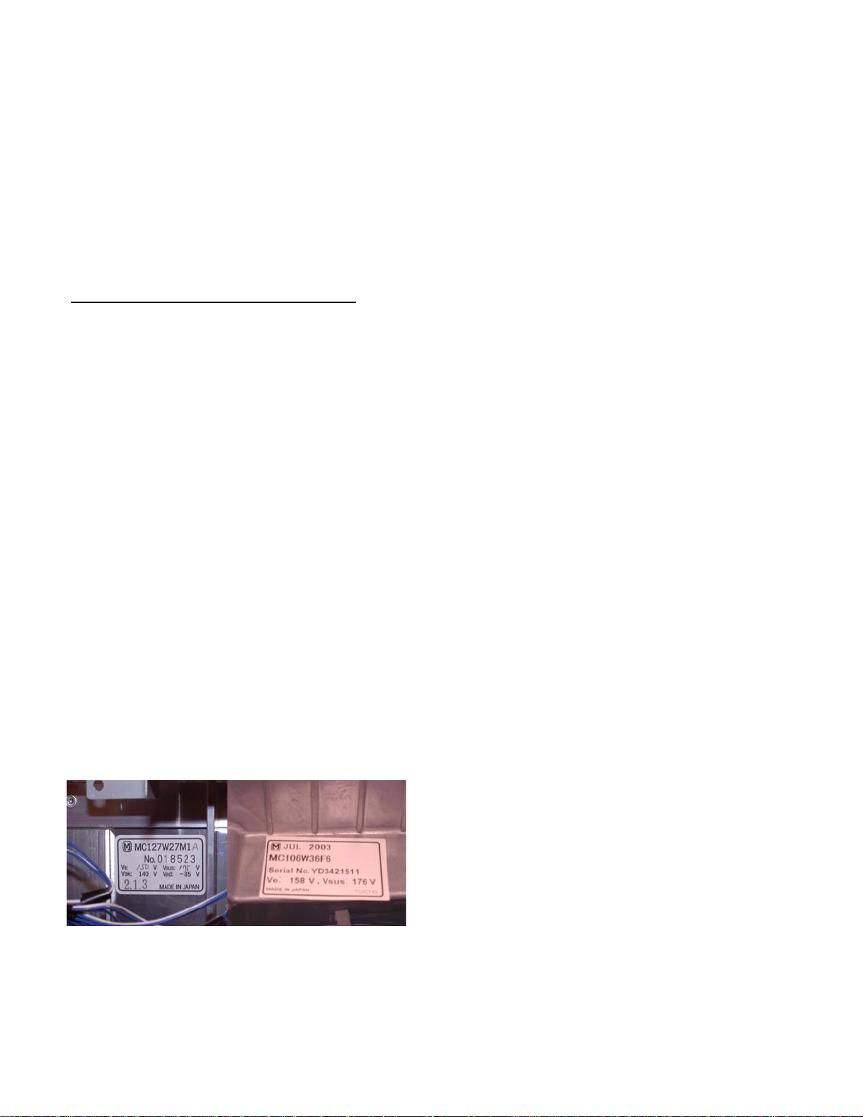
6. Fill in the "Panel’s serial number code" as
indicated on the label located on the back of the
panel. If the label resembles the depiction in fig.
1A, the code is the three-digit number "2.1.3" at
the bottom of the label. If it resembles the
depiction in fig. 1B, the code is the date at the top
of the label “JUL 2003”.
7. Enter "Date of Purchase" and "Date Service
Requested".
Fig. 1A
8. Enter the authorization number supplied by the
Hotline agent in the "Authorization #" field.
Fig. 1B
16. Verify the warranty repair status. Delete the
inappropriate status and then enter your name
next to "Confirmed by".
17. Skip the "Defective Parts Return Status" until the
repair is complete.
18. Skip the box labeled "Arrival Condition" (gray
shaded area)
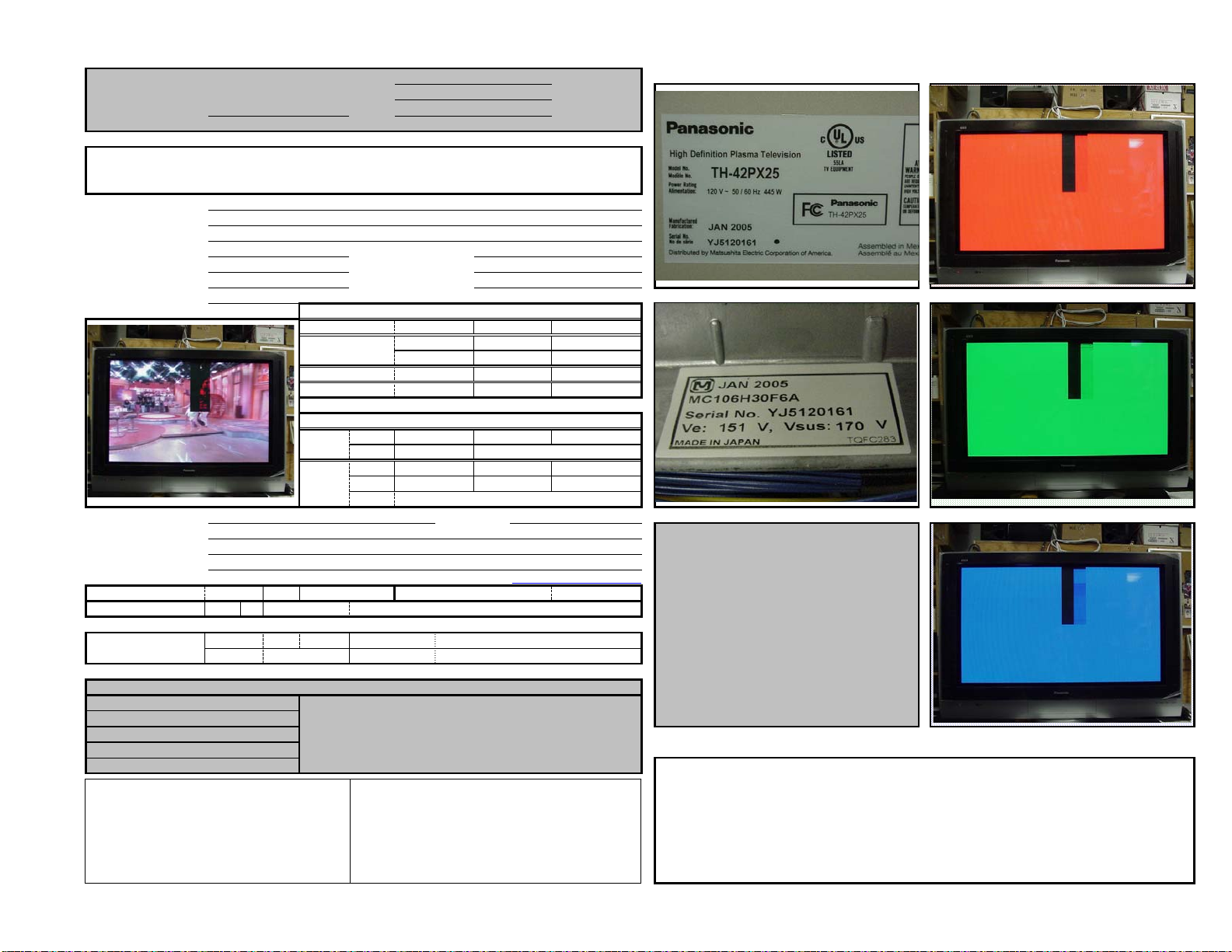
19. In picture placeholder 1 on the top center of the
report, insert a clear digital picture, showing the
serial number label of the unit being serviced.
The serial number must be legible.
20. In picture placeholder 2, insert or attach a picture,
showing the serial number label of the panel.
Refer to figure 1. (The panel label is visible only
after the back cover of the unit is removed.) The
serial number must be legible.
21. In picture placeholder 4, insert a picture of the
defect as it appears when the Green and Blue
fields are turned off, and only the Red field is
active. (See the service manual of the unit for
instructions.)
Page 1 of 2

22. In picture placeholder 5, insert or attach a picture
of the defect as it appears when the Red and
Blue fields are turned off, and only the Green
field is active. (See the service manual of the unit
for instructions.)
23. In picture placeholder 6, insert or attach a picture
of the defect as it appears when the Red and
Green fields are turned off, and only the Blue
field is active. (See the service manual of the unit
for instructions.)
24. In the "Comments" section, describe the special
circumstances, troubleshooting and any repairs
attempted.
How to Insert an Image in a Picture
Box
Capture all images with a digital camera, using a
resolution high enough to show the desired details in
each image, but not excessively high, resulting in
excessive file sizes. ISP bandwidth and mailbox
sizes are often insufficient to accommodate large
files.
1. Click a picture box in the form.
2. From the menu, click "Insert" from Excel's menu*.
A scroll-box appears.
25. Save the Excel Workbook under a new name
using the customer's last name and the date.
(Example: "Smith 091703.xls")
After Replacing the Panel
26. The defective panel must be shipped to the
address provided on the prepaid return label
included with the replacement panel. Please
follow the instructions carefully.
IMPORTANT: Defective panel must be
returned to Panasonic before parts
warranty reimbursement can be made.
27. After shipping the defective panel to the address
indicated on the label and as per instructions
packaged with the new panel, complete the
report by deleting the word "NO" next to
"Returned", leaving the "YES" in the "Defective
Parts Return Status" box. Enter the name of the
person confirming the shipment, the carrier
information, and the tracking # in the appropriate
spaces.
3. From the scroll-box, select "Picture". Another
scroll-box appears.
4. Click "From File". An Explorer window opens.
5. Select the desired file.
6. Click "Insert".
7. If the picture is larger or smaller than the box in
the form, click a corner of the image and drag to
resize.
* Use the "insert" function from Excel's "Insert" menu,
not from the "Insert" available by right-clicking. When
using Windows' right-click function, a picture file
copied to the clip-board cannot be inserted or pasted,
unless the image itself (the file contents) is copied to
the clip-board.
Click here to open the Plasma Display Panel
Replacement Report form (for viewing)
Click here for an example of a completed Plasma
Display Panel Replacement Report
28. When the repair is complete and the defective
panel shipped, complete the remainder of the
report by entering the "Date Completed".
29. Review the report for completeness. Then email
the report to the appropriate address listed on the
bottom of the report.
30. When a completed report, with the six pictures is
received by the Hotline, and the defective panel
is returned, an additional $100.00 will be credited
to warranty claim.
Revised 11/22/2005
Page 2 of 2
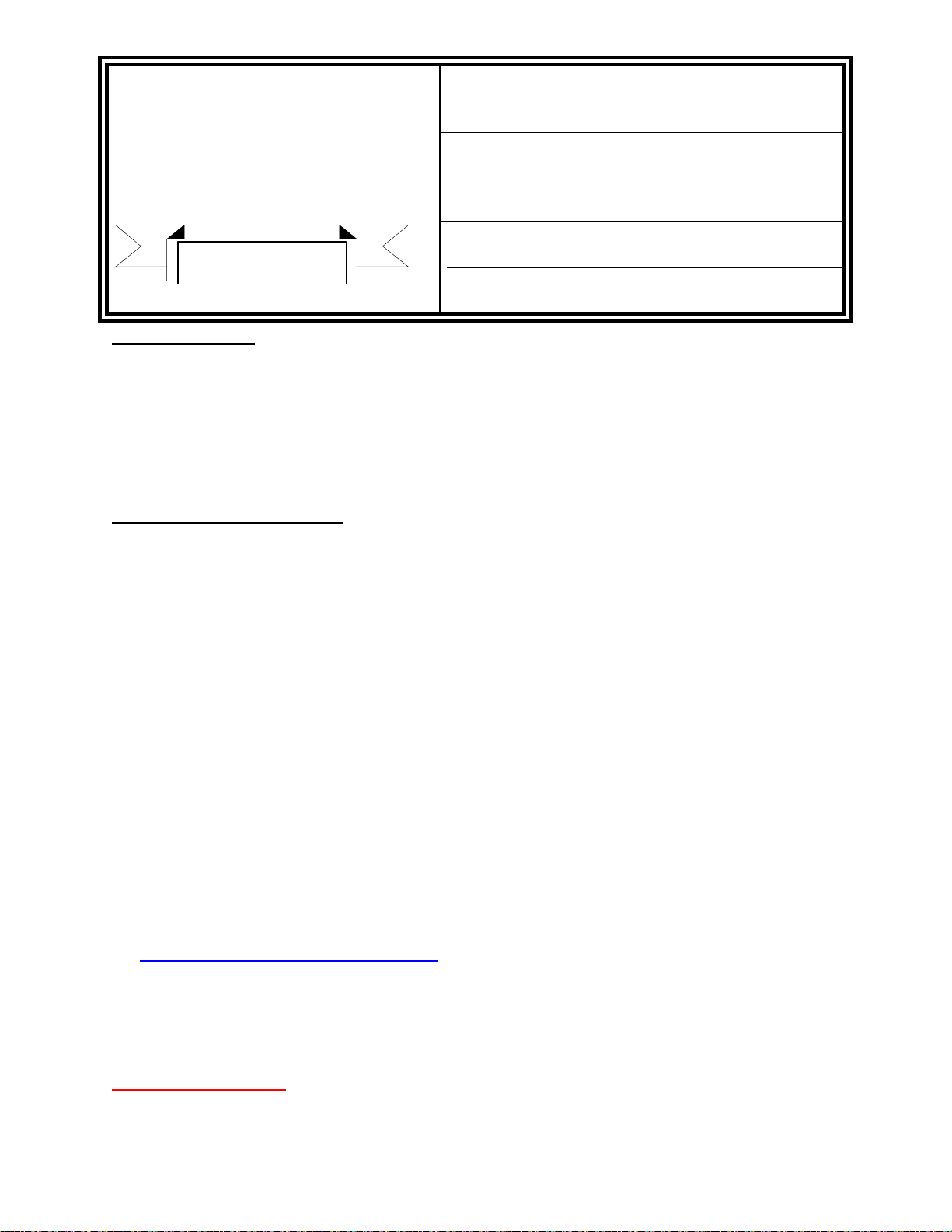
Plasma Display Panel Replacement Report
m
(Panasonic use only)
Company:
Panel Warranty: YES NO
Reporter: Fax:
Symptom:
Black bar, top center screen, halfway down.
Panel Serial No. Code:
Picture of Symptom:
mode must be attached here or attached
Telephone: E-Mail:
Customer Name:
Cust Address:
City / State / Zip:
Work Order # :
Model # :
Serial # :
This picture is for
A picture of the symptom as it
illustration only;
appears in normal operation
do not copy and
use in your panel
to the email with the report.
Servicer's Name:
Address:
City / State / Zip:
Telephone: Fax # : E-Mail:
Operation Time: Hours: 105
Warranty Status:
Defective Panel
Return Status:
report.
Contact:
PASC / PBTSC
John C. Consumer
123 Main St.
Anytown, CA 98765
11-562485-00
TH-42PX25
YJ1520161
YJ1520161
Service Center
John M. Servicer
563 Timbuktu Drive
New Town, CA 98764
574.123.4567
YES
Returned:
Carrier: World Shippers
Confirmed by:
YES
Replacement Date:
Report Date:
Date Service Requested:
Picture Mode:
Aspect:
White Balance:
Manual W/B:
Signal
Signal
Source:
NTSC VGA/SVGA
Format: RGB
CTV PC
DVC
Other
574.123.4568
66
John M. Servicer
Confirmed by:
Date of Purchase:
Date Completed:
Authorization # : 0118795487
Dynamic Normal
AUTO
ZOOM1
WARM
ON
CONNECTION
PAL/SECAM
COMPONENT
VCR
STB
Tracking # :
November 30, 2005
December 27, 2005
January 6, 2006
SETTING
Account # :
Power ON/OFF Times:
JUST
ZOOM2
NORMAL
OFF
PAL60
ALL
DVD
ALL
0054321-0012
JohnServicer@Provider.co
John M. Servicer
A1ZT546584525478
4:3
16:9
COOL
1- Serial Number of Unit
This picture is for
Pictures
illustration only;
Picture of the serial number of the
unit must be attached here or attached to
The unit serial number must be legible.
2- Serial Number of Panel
do not copy and
use in your panel
the email with the report.
report.
This picture is for
illustration only;
do not copy and
Picture of the Serial Number of the
defective panel must be attached here or
use in your panel
report.
attached to the email with the report.
The panel serial number must be legible.
3- Factory Use Only
( Factory Use Only )
4- Red Screen
This picture is for
A picture of the defect in Red Screen mode
must be attached here or attached to the email with
5- Green Screen
illustration only;
do not copy and
use in your panel
the report.
report.
This picture is for
illustration only;
A picture of the defect in Green Screen mode
must be attached here or attached to the email with
6- Blue Screen
do not copy and
use in your panel
the report.
report.
This picture is for
A picture of the defect in Blue Screen mode
must be attached here or attached to the email with
illustration only;
do not copy and
use in your panel
the report.
report.
ARRIVAL CONDITION ( Factory Use Only )
DATE:
COURIER:
International Operation Department
Television System Products Division Plasma Display Division
Matsushita Electric Industrial Co., Ltd. AVC company Matsushita Electric Industrial Co., Ltd.
PASCTECHHOTLINE@US.PANASONIC.COM
1-1 Matsushita-Cho, Ibaraki, Osaka 567-0026 JAPAN 1-1 Saiwai-cho Takatsuki, Osaka 569-1193 JAPAN
Tel 81-726-24-7743, Fax 82-726-22-8205 Tel 81-726-82-6647, Fax 81-726-82-6679
** Gray shaded areas are for Panasonic's use only
CONSUMER MODEL
E-Mail this report to:
Panasonic Technical Hotline
50 Meadowlands Parkway 2B-6
Secaucus, NJ 07094
(800) 743-2335
PANEL SERIAL # :
SYMPTOM:
Plasma Sales Group
BROADCAST MODEL
E-Mail this report to:
PEEKJ@US.PANASONIC.COM
Panasonic Broadcast & Television Systems Co.
50 Meadowlands Parkway 2A-4
Secaucus, NJ 07094
(201) 392-4355
Comments - Describe special circumstances, troubleshooting and repairs attempted:
Replaced the "C' board.
Form PR-20051201
PANASONIC SERVICES
SERVICE ADMINISTRATIVE BULLETIN
COMPANY
50 Meadowland Parkway
Secaucus, New Jersey 07094
SUBJECT: PLASMA PANEL
REPLACEMENT – ADDITIONAL HANDLING
CHARGE REIMBURSEMENT
NUMBER: 05-11-005
SERVICE POLICY
DEPARTMENT
DATE: November 22, 2005
BACKGROUND:
In the effort to continuously improve the performance of our products, we need your
cooperation in completing the PDP report, e-mailing digital pictures and returning the
defective panel. PASC recognizes the additional time to perform these tasks so we will be
adding $100 to the warranty claim at the time of processing to compensate for the extra
time and to show appreciation for the extra efforts in assisting Panasonic in improving the
quality of our product offerings.
POLICY & PROCEDURES:
1. This is effective as of December 1, 2005
2. This policy applies to all B34 servicers authorized to replace the Plasma panels.
3. The servicer will take 6 digital pictures of the defective panel showing the following:
x The symptom
x The serial number of the unit
x The serial number of the defective
x The red screen
x The blue screen
x The green screen
panel
4. The servicer will complete a PDP report, which details the problems with the panel.
The report is available in PASS from the Technical Resource Center:
x Log in to PASS
x Go to Technical Resource Center
x Click on CONTINUE
x Click on VIDEO
x Click on PLASMA
x On the right side, go the box: SERVICE POLICIES AND RELATED FORMS
x Click on PLASMA PANEL FIELD REPORT
x This will take you to the instructions and the PDP report.
5. The PDP report and the pictures are to be e-mailed to:
pasctechhotline@us.panasonic.com
6. Warranty Claims will verify that the PDP report and the digital pictures have been
received, as well as the defective Plasma panel.
7. Upon verification of receipt of all 3 items, Warranty Claims will add the $100 additional
handling charge to the claim in the “Other” field.
IMPORTANT NOTE:
The $100 will NOT be added to a claim unless ALL 3 items (the
completed PDP report, the required 6 pictures and the defective
panel) are returned to PASC.
1

Unpacking and Repacking the Plasma Panel
Panel Replacement Precautions
Handling
Use extreme care when handling the Plasma Display Panel. Due to the size and
fragility, it is recommended that two individuals handle the Plasma Panel to avoid
accidental damage.
The glass used in the plasma panel is thin, and its structure is extremely susceptible to
impact. Rough handling of the unit can crack the glass or cause pixel defect errors. Be
sure to transport the panel in the upright position. The unit is designed to absorb force
vertically not horizontally.
Numerous flexible printed leads with extremely soft structure are used around the panel.
Be very careful during handling not to damage these by pulling, bending, or subjecting
them to excessive force. When inserting a ribbon cable into a socket, verify that the
cable is straight. Angled insertion can create an electrical short circuit and permanently
damage the panel.
High Voltage
Plasma Display Panels use a high voltage power supply. Disconnect the AC from the
unit and wait one minute for the voltage to dissipate.
Static
Anti-static measures should be applied, especially when connecting and disconnecting
the ribbon cables.
Scratches
A protective sheet is attached to the back of the replacement panel to prevent scratches
and accumulation of debris. Be sure to remove the protective sheet and wipe the
surface with a soft cloth before installation.
Assembly
A low torque setting is recommended when installing screws in the panel assembly.
Preparation of the new panel
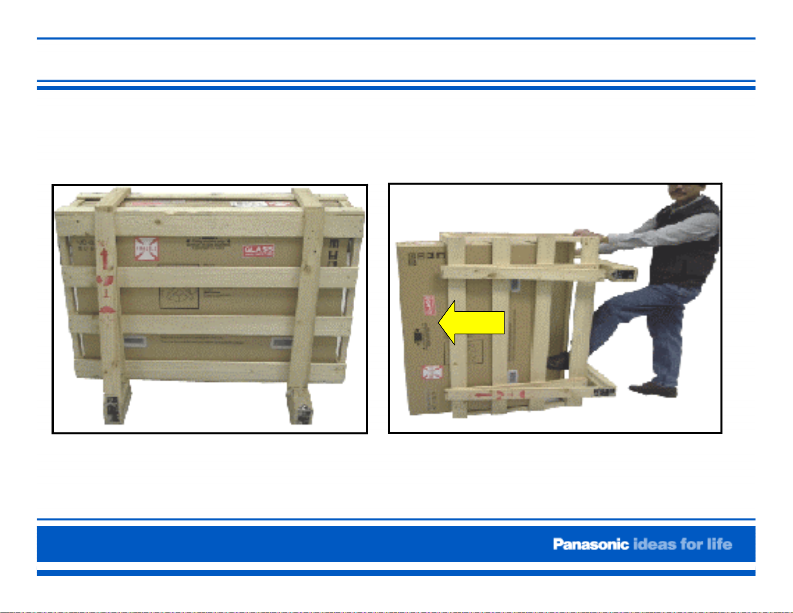
1) The replacement panel is shipped in a special
shipping crate. Retain this crate to return the
defective panel.
Page 1 of 2
Figure 1
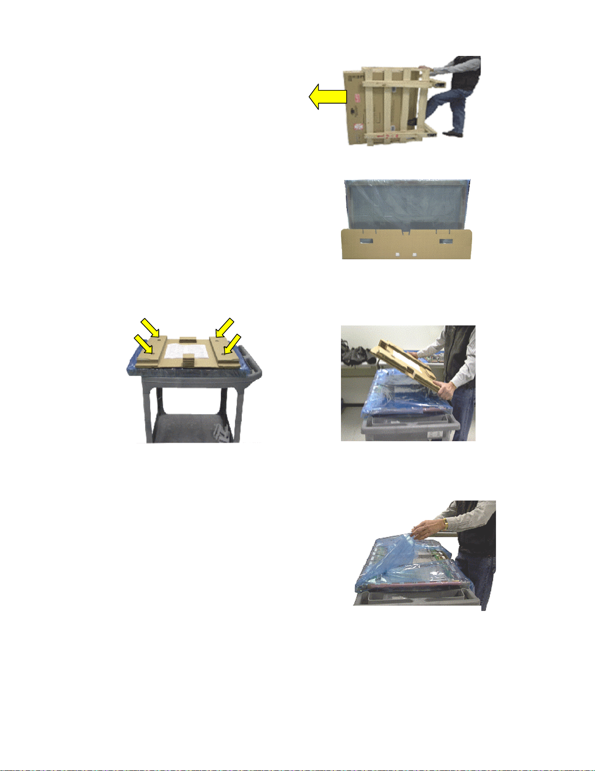
2) Carefully remove the top of the crate,
remember you will have to reuse the crate
to return ship the defective panel. Slide the
panel out the opened end.
Figure 2
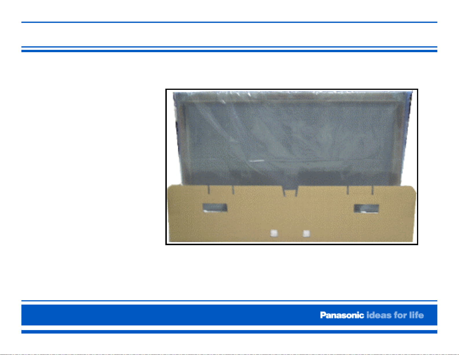
3) The replacement panel is packed in an
escutcheon frame and a cardboard
panel. Protective cushioning surrounds the
panel. These items must be saved and
used to return the defective panel.
Figure 3
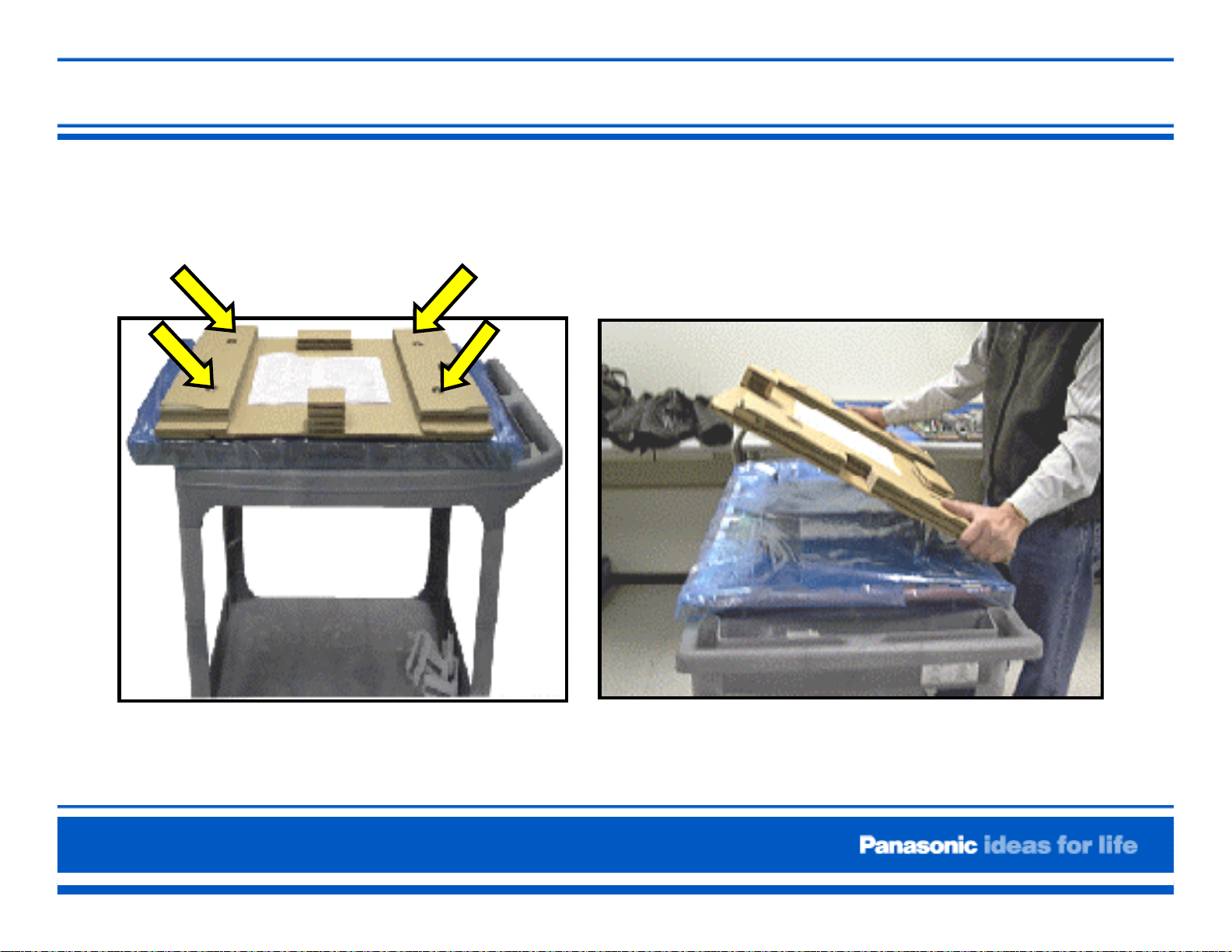
4) Remove the four screws that secure the protective cardboard on the new panel.
Place the protective cardboard aside.
Figure 4a
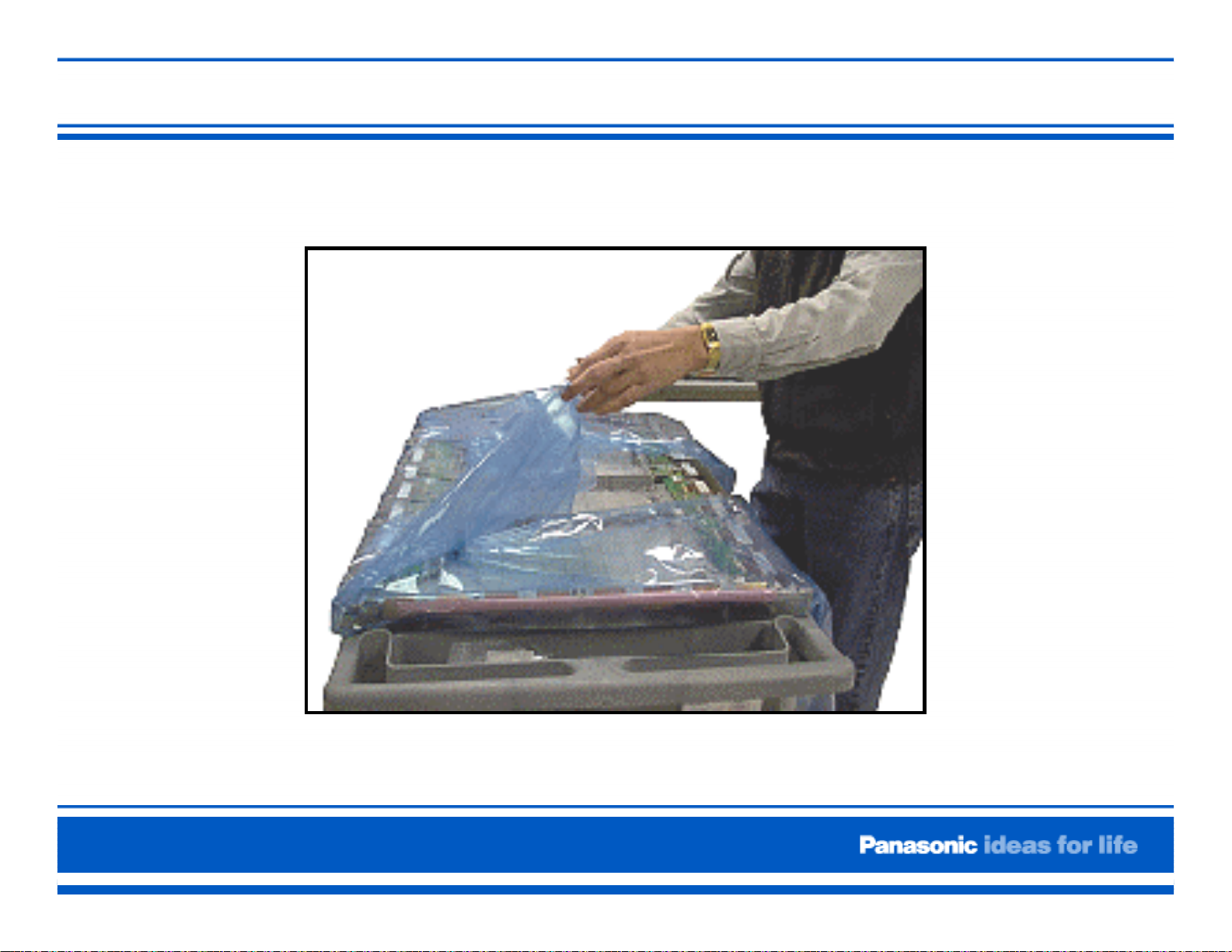
Unwrap the protective packaging from the new
panel.
Important Note:
The new panel comes with the “C” boards
preinstalled. However, the jumper ribbon
cables that connect the “C” boards may not be
included. Check for board jumpers. If missing,
remove them from the old panel and transfer
them to the new panel.
5) Reverse the order of the steps listed above to repack the defective panel for
return shipment to Panasonic.
Page 2 of 2
Figure 4b
Figure 5

Agenda
Equipment List
Panel Handling
Preparation of New Panel
PCB Description
Disassembly and Reassembly Procedure
Lead Dressing
Adjustment ( Driver Setup) Procedure
Adjustment (White Balance) of GP8DU Chassis)
Adjustment (White Balance) Procedure of older Panels
Examples of Defective Panels

Equipment List:
Electric Screwdriver (Part # EY6220B or equivalent)
Digital Volt Ohmmeter
Oscilloscope
Isolation Transformer
Anti-static 5 foot by 4 foot foam cushioning
Plasma Stand (Part # TY-ST05K or equivalent)
Screw storage bin
Large flat work area
Colorimeter for white balance adjustment (Sencore CP288 or
equivalent)
Video Signal Generator capable of providing NTSC, 480p, 720p and
1080i with adjustable brightness levels. (Sencore VP300 or
equivalent)
Page 1
Handling Precaution
Thin Glass = Susceptibility to impact
Rough Handling = Cracked glass or pixel defects
Improper Transportation = Unit should always be in the upright
position.
Leads or Ribbon Cables = No pulling, no bending, no excessive force
Ribbon cables must be straight when inserted into sockets. Angle
insertion can create an electrical short circuit.
Anti-static measures must be applied when disconnecting and
connecting ribbon cables.
Electric screwdrivers must have low torque setting to avoid damaging
the panel.
Page 1
Preparation of the New Panel (1)
Page 2
Preparation of the New Panel (2)
Preparation of the new Panel (2)
Caution: Use
extreme care when
handling the
Plasma Display
Panel. The glass
used in the plasma
panel is thin, and
its structure is
extremely
susceptible to
impact.
Page 3
Preparation of the New Panel (3)
Page 3
Preparation of the New Panel (4)
Page 3
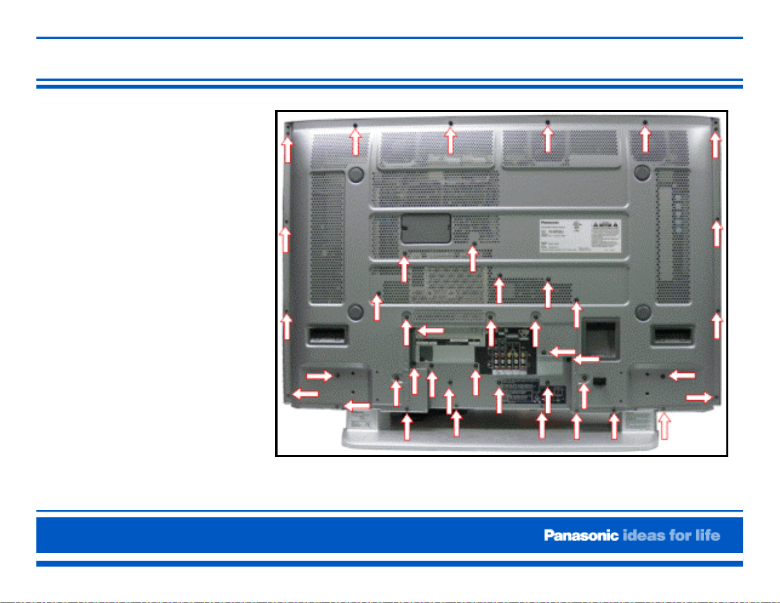
Rear Cabinet Removal
Remove the 43
screws as indicated
and then pull away
the rear cover. Place
it in a secure
location.
Weight:
TH-37PX50U = 66.14lb.
TH-42PX50U = 76.06lb.
TH-50PX50U = 99.21lb.
Figure 7. Back Cover Screws
Note:The unit can be awkward for one person, be sure to have someone assist you.
Page 4
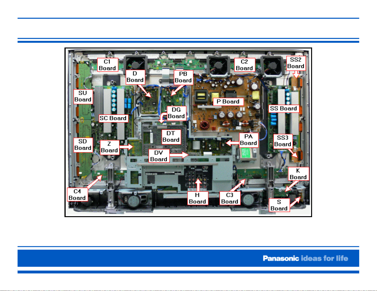
Board Layout
Page 4
Figure 8. Board Layout
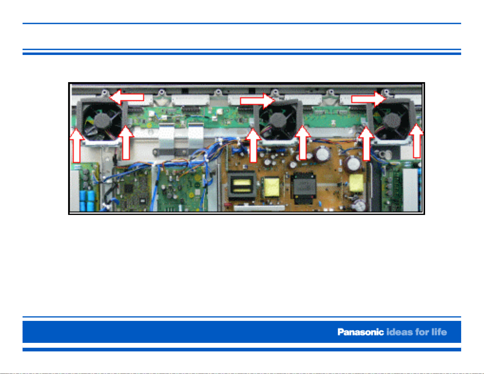
Removal of the fans
Figure 9. Fans Location
1. Remove the three screws that secure each of the
three fans.
2. Place the fans in a secure location
Page 5
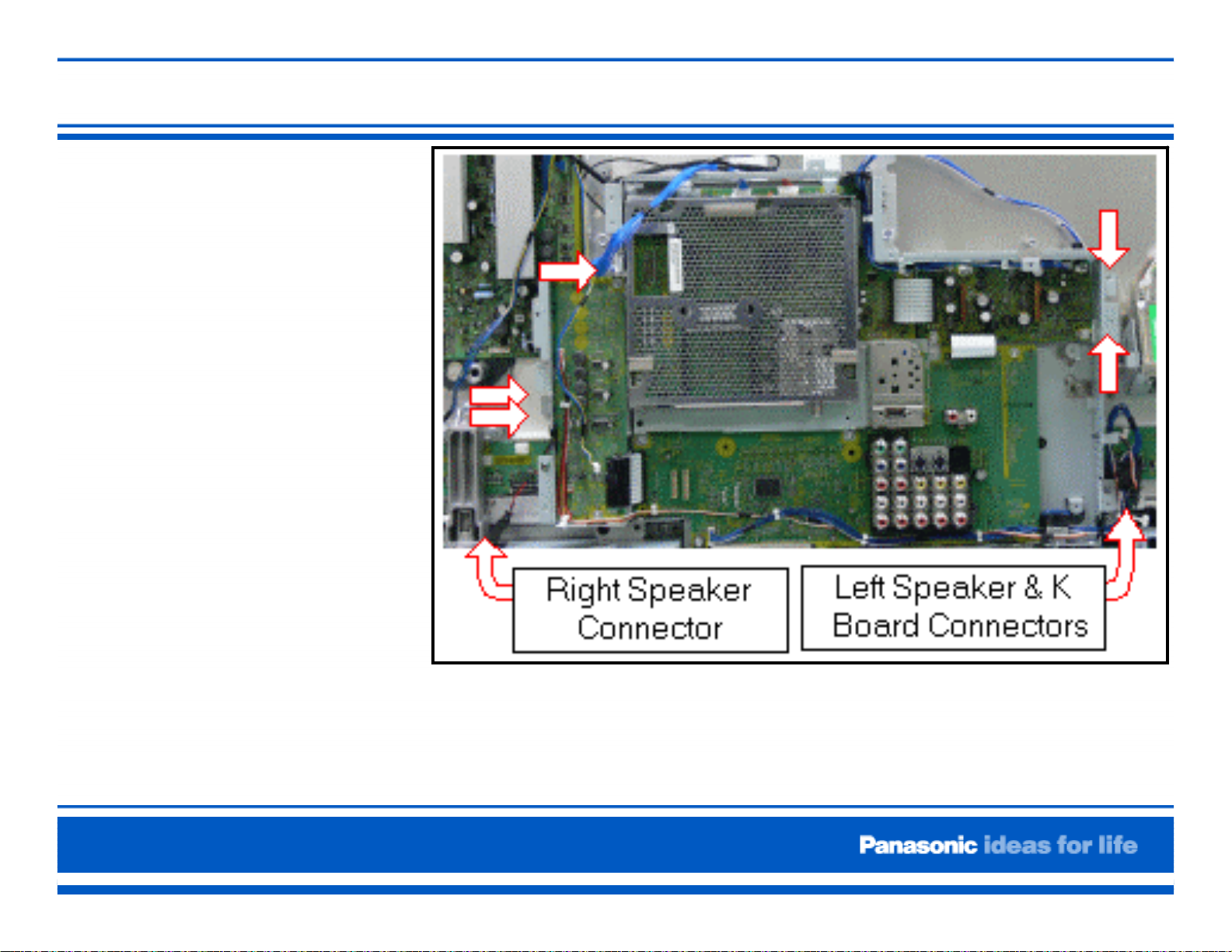
Removal of the Metal Frame
1. Disconnect the speaker
connectors (SP-L and
SP-R) and the black
connector that couples
the K board and the
DG board.
2. Disconnect the
connectors DG3 and
DG5 of the DG board,
PB7 of the PB board,
and PA10 of the PA
board.
3. Remove the five
screws that hold the
metal frame as
indicated in figure 11.
Page 6
Figure 11. Metal Frame
 Loading...