

Panasonic TH-37PWD6UY, TH-42PWD6UY, TH-42PHD6UY, TH-50PHD6UY User Manual
®
Operating Instructions
PLASMA DISPLAY
Progressive Wide Plasma Display
R
E
T
N
E
+
L
O
V
–
U
N
E
M
T
U
P
N
I
Y
B
D
N
A
/
T
S
-
R
R
N
E
O
W
R
E
O
P
W
O
P
G
Model No.
TH-37PWD6
TH-42PWD6
High Definition Plasma Display
Model No.
TH-42PHD6
TH-50PHD6
Before connecting, operating or adjusting this product, please read these instructions completely . Please keep this manual
for future reference.
English
TQBC0570
WARNING
RISK OF ELECTRIC SHOCK
DO NOT OPEN
WARNING: To reduce the risk of electric shock, do not remove cover or back.
No user-serviceable parts inside. Refer servicing to qualified service personnel.
The lightning flash with
arrow-head within a triangle
is intended to tell the user
that parts inside the product
are a risk of electric shock to
persons.
WARNING: To prevent damage which may result in fire or shock hazard, do not expose this apparatus to rain
or moisture.
Do not place containers with water (flower vase, cups, cosmetics, etc.) above the set.
(including on shelves above, etc.)
WARNING: 1) To prevent electric shock, do not remove cover. No user serviceable parts inside. Refer servicing to
qualified service personnel.
2) Do not remove the grounding pin on the power plug. This apparatus is equipped with a three pin
grounding-type power plug. This plug will only fit a grounding-type power outlet. This is a safety feature.
If you are unable to insert the plug into the outlet, contact an electrician.
Do not defeat the purpose of the grounding plug.
The exclamation point within
a triangle is intended to tell
the user that important
operating and servicing
instructions are in the papers
with the appliance.
2

Important Safety Instructions
1) Read these instructions.
All the safety and operating instructions should be read before the appliance is operated.
2) Keep these instructions.
The safety and operating instructions should be retained for future reference.
3) Heed all warnings.
All warnings on the appliance and in the operating instructions should be adhered to.
4) Follow all instructions.
All operating and use instructions should be followed.
5) Do not use this apparatus near water.
For example, near a bathtub, wash bowl, kitchen sink, or laundry tub, in a wet basement, or near a swimming pool, and
the like.
6) Clean only with dry cloth.
Do not use liquid cleaners or aerosol cleaners. Use a dry cloth for cleaning.
7) Do not block any ventilation openings. Install in accordance with the manufacturer’s instructions.
Slots and Openings in the cabinet are provided for ventilation and to ensure reliable operation of the product and to
protect it from overheating. The openings should never be blocked by placing the product on a bed, sofa, rug, or other
similar surface.
8) Do not install near any heat sources such as radiators, heat registers, stoves, or other apparatus (including amplifiers)
that produce heat.
This product should not be placed in a built-in installation such as a bookcase or rack unless proper ventilation is
provided or the manufacturer’s instructions have been adhered to.
9) Do not defeat the safety purpose of the polarized or grounding-type plug. A polarized plug has two blades with one wider
than the other. A grounding type plug has two blades and a third grounding prong. The wide blade or the third prong are
provided for your safety. If the provided plug does not fit into your outlet, consult an electrician for replacement of the
obsolete outlet.
10) Protect the power cord from being walked on or pinched particularly at plugs, convenience receptacles, and the point
where they exit from the apparatus.
11) Only use attachments / accessories specified by the Manufacturer.
12) Use only with the cart, stand, tripod, bracket, or table specified by the manufacturer, or sold with the
apparatus. When a cart is used, use caution when moving the cart / apparatus combination to avoid
injury from tip-over.
Quick stops, excessive force, and uneven surfaces may cause the appliance and cart combination to
overturn.
13) Unplug this apparatus during lightning storms or when unused for long periods of time.
This will prevent damage to the product due to lightning and power-line surges.
14) Refer all servicing to qualified service personnel. Servicing is required when the apparatus has been damaged in any
way, such as power-supply cord or plug is damaged, liquid has been spilled or objects have fallen into the apparatus,
the apparatus has been exposed to rain or moisture, does not operate normally, or has been dropped.
15) To prevent electric shock, ensure the grounding pin on the AC cord power plug is securely connected.
3

Dear Panasonic Customer
Welcome to the Panasonic family of customers. We hope that you will have many years of enjoyment
from your new Plasma Display.
To obtain maximum benefit from your set, please r ead these Instructions before making any adjustments,
and retain them for future reference.
Retain your purchase receipt as well, and record the model number and serial number of your set in
the space provided on the rear cover of these instructions.
Table of Contents
Important Safety Instructions ....................................... 3
FCC STATEMENT ........................................................... 5
Safety Precautions......................................................... 6
Accessories .................................................................... 8
Accessories Supplied.................................................... 8
Remote Control Batteries.............................................. 8
Connections ................................................................... 9
PC Input Terminals connection ................................... 10
SERIAL Terminals connection..................................... 11
AV & COMPONENT connection ................................. 12
RGB signal (R, G, B, HD, VD) ....................................12
Power ON/OFF.............................................................. 13
AC cord conncection................................................... 13
Power ON/OFF ........................................................... 13
Basic Controls.............................................................. 14
On-Screen Menu Displays........................................... 16
Input Signal Selection.................................................. 18
Select the Input Signal ................................................ 18
Selecting the ON-Screen Menu Language ................. 18
ASPECT Controls......................................................... 19
Adjusting PICTURE POSITION/SIZE........................... 20
SOUND Adjustment ..................................................... 21
MUTE .......................................................................... 21
PICTURE Adjustments................................................. 22
ADVANCED SETTINGS .............................................23
PRESENT TIME SETUP/SET UP TIMER .....................24
PRESENT TIME SETUP............................................. 24
SET UP TIMER........................................................... 25
SCREENSAVER (For preventing after-images) ......... 26
Setup of SCREENSAVER Time.................................. 27
Reduces screen after-image....................................... 27
SIDE BAR ADJUST .................................................... 28
Digital Zoom ................................................................. 29
Reduces power consumption ..................................... 30
Customizing the Input labels....................................... 30
SET UP for MULTI DISPLAY ........................................ 31
How to setup MULTI DISPLAY.................................... 31
How to set the Display location number for each Plasma Display............
SET UP for Input Signals............................................. 33
COMPONENT/RGB IN SELECT ................................ 33
3D Y/C FILTER – For NTSC Video images ............................... 33
COLOR SYSTEM / Panasonic AUTO ......................... 34
3:2 PULLDOWN..........................................................34
SYNC ..........................................................................35
H-FREQ. (kHz)/V-FREQ. (Hz) .................................... 35
Troubleshooting........................................................... 36
VIDEO/COMPONENT/RGB/PC input signals ............. 37
Specifications............................................................... 38
32
4
FCC STATEMENT
FCC STATEMENT
This equipment has been tested and found to comply with the limits for a Class A digital device, pursuant to part 15 of
the FCC Rules. These limits are designed to provide reasonable protection against harmful interference when the
equipment is operated in a commercial environment.
This equipment generates, uses, and can radiate radio frequency energy and, if not installed and used in accordance
with the instruction manual, may cause harmful interference to radio communications. Operation of this equipment in
a residential area is likely to cause harmful interference in which case the user will be required to correct the interference
at his own expense.
FCC CAUTION:
Pursuant to 47CFR, Part 15.21 of the FCC rules, any changes or modifications to this monitor not expressly
approved by Matsushita Electric Corporation of America could cause harmful interference and would void the
user’s authority to operate this device.
Attach the ferrite core:
The ferrite cores provided as a supplied accessory must be used when connecting this Plasma Display to video
equipment. (see page 10, 11)
FCC CAUTION:
To assure continued compliance and possible undesirable interference, the provided ferrite cores must be
used when connecting this plasma display to video equipment; and maintain at least 40 cm of spacing from
other peripheral devices. Refer to instructions on pages 10, and 11.
CANADIAN NOTICE:
This Class A digital apparatus complies with Canadian ICES-003.
Note:
Do not allow a still picture to be displayed for an extended period, as this can cause permanent after-image
to remain on the Plasma Display.
Examples of still pictures include logos, video games, computer images, teletext and images displayed in
4:3 mode.
Trademark Credits
VGA is a trademark of International Business Machines Corporation.
•
Macintosh is a registered trademark of Apple Computer, USA.
•
S-VGA is a registered trademark of the Video Electronics Standard Association.
•
Even if no special notation has been made of company or product trademarks, these trademarks have been fully
respected.
5

Safety Precautions
WARNING
Set up
Do not place the Plasma Display on sloped or unstable surfaces.
The Plasma Display may fall off or tip over.
•
Do not place any objects on top of the Plasma Display.
If water spills onto the Plasma Display or foreign objects get inside it, a short-circuit may occur which could result in fire
•
or electric shock. If any foreign objects get inside the Plasma Display, please consult an Authorized Service Center.
Do not cover the ventilation holes.
Doing so may cause the Plasma Display to overheat, which can cause fire or damage to the Plasma Display.
•
If using the pedestal (optional accessory), leave a space of 3 15/16” (10 cm) or more at the top, left and right, 2 3/8”
cm) or more at the bottom, and 2 3/4” (7 cm) or more at the rear. If using some other setting-up method, leave a
space of 3 15/16” (10 cm) or more at the top, bottom, left and right, and 3/4” (1.9 cm) or more at the rear.
Avoid installing this product near electronic equipment that easily receives electromagnetic waves.
It may cause interference in image, sound, etc. In particular, keep video equipment away from this product.
•
AC Power Supply Cord
The Plasma Display is designed to operate on 120 V AC, 50/60 Hz.
(6
Securely insert the power cord plug as far as it will go.
If the plug is not fully inserted, heat may be generated which could cause fire. If the plug is damaged or the wall socket
•
plate is loose, they should not be used.
Do not handle the power cord plug with wet hands.
Doing so may cause electric shocks.
•
Do not do anything that might damage the power cable. When disconnecting the power cable, hold the plug, not
the cable.
Do not make any modifications, place heavy objects on, place near hot objects, heat, bend, twist or forcefully pull the
•
power cable. Doing so may cause damage to the power cable which can cause fire or electric shock. If damage to the
cable is suspected, have it repaired at an Authorized Service Center.
If the Plasma Display will not be used for a long period of time, unplug the power cord from the wall outlet.
If problems occur during use
If a problem occurs (such as no picture or no sound), or if smoke or an abnormal odor is detected from the Plasma
Display, unplug the power cord immediately.
Continuous use of the Display under these conditions might cause fire or permanent damage to the unit. Have the
•
Display evaluated at an Authorized Service Center. Services to the Display by any unauthorized personnel are strongly
discouraged due to its high voltage dangerous nature.
If water or foreign objects get inside the Plasma Display, if the Plasma Display is dropped, or if the cabinet
becomes damaged, disconnect the power cord plug immediately.
A short may occur, which could cause fire. Contact an Authorized Service Center for any repairs that need to be made.
•
6

Safety Precautions
CAUTION
This Plasma Display is for use only with the following optional accessories. Use with any other type of optional
accessories may cause instability which could result in the possibility of injury.
(All of the following accessories are manufactured by Matsushita Electric Industrial Co., Ltd.)
Speakers .............................................................TY-SP37P5W-K (TH-37PWD6),
•
Pedestal .............................................................. TY-ST05-K
•
Wall stand............................................................ TY-ST42PW1
•
Mobile stand........................................................ TY-ST42PF3 (TH-42PWD6, TH-42PHD6, TH-50PHD6)
•
Wall-hanging bracket (vertical)............................ TY-WK37PV3 (TH-37PWD6),
•
Wall-hanging bracket (angled) ............................ TY-WK42PR1 (TH-42PWD6, TH-42PHD6, TH-50PHD6)
•
Wall-hanging bracket (drawer type) .................... TY-WK42DR1 (TH-42PWD6, TH-42PHD6, TH-50PHD6)
•
Ceiling unit ...........................................................TY-CE42PS1
•
BNC Component Video Terminal Board................ TY-42TM6A
•
BNC Composite Video Terminal Board ................. TY-42TM6B
•
RCA Component Video Term inal Board............... TY-42TM6Z
•
RCA Composite Video Term i nal Board ................ TY-42TM6V
•
RGB (Digital) Terminal Board .............................. TY-42TM6D
•
RGB Active Through T erminal Board ..................TY -42TM6G
•
PC Input Terminal Board ...................................... TY-42TM6P
•
Always be sure to ask a qualified technician to carry out set-up.
TY-SP42P5W-K (TH-42PWD6, TH-42PHD6),
TY-SP50P5W-K (TH-50PHD6)
TY-WK42PV1(TH-42PWD6, TH-42PHD6, TH-50PHD6)
When using the Plasma Display
Do not bring your hands, face or objects close to the ventilation holes of the Plasma Display.
Top of the Plasma Display is usually very hot due to the high temperature of exhaust air being released through the
•
ventilation holes. Burns or personal injuries can happen if any body parts are brought too close. Placing any object near the
top of the display could also result in heat damages to the object as well as to the Display if its ventilation holes are blocked.
Be sure to disconnect all cables before moving the Plasma Display.
Moving the Display with its cables attached might damage the cables which, in turn, can cause fire or electric shock.
•
Disconnect the power plug from the wall outlet as a safety precaution before carrying out any cleaning.
Electric shocks can result if this is not done.
•
Clean the power cable regularly to prevent it from becoming dusty.
Built-up dust on the power cord plug can increase humidity which might damage the insulation and cause fire. Unplug
•
the cord from the wall outlet and clean it with a dry cloth.
This Plasma Display radiates infrared rays, therefore it may affect other infrared communication equipment.
Install your infrared sensor in a place away from direct or reflected light from your Plasma Display.
Cleaning and maintenance
The front of the display panel has been specially treated. Wipe the panel surface gently using only a cleaning
cloth or a soft, lint-free cloth.
If the surface is particularly dirty, soak a soft, lint-free cloth in a weak detergent solution and then wring the cloth to
•
remove excess liquid. Use this cloth to wipe the surface of the display panel, then wipe it evenly with a dry cloth, of the
same type, until the surface is dry.
Do not scratch or hit the surface of the panel with fingernails or other hard objects. Furthermore, avoid contact with volatile
•
substances such as insect sprays, solvents and thinner, otherwise the quality of the surface may be adversely affected.
If the cabinet becomes dirty, wipe it with a soft, dry cloth.
If the cabinet is particularly dirty , soak the cloth in a weak detergent solution and then wring the cloth dry. Use this cloth
•
to wipe the cabinet, and then wipe it dry with a dry cloth.
Do not allow any detergent to come into direct contact with the surface of the Plasma Display.
•
If water droplets get inside the unit, operating problems may result.
Avoid contact with volatile substances such as insect sprays, solvents and thinner , otherwise the quality of the cabinet
•
surface may be adversely affected or the coating may peel off. Furthermore, do not leave it for long periods in contact
with articles made from rubber or PVC.
Note:
Do not allow a still picture to be displayed for an extended period, as this can cause a permanent after-image to remain on the Plasma Display .
Examples of still pictures include logos, video games, computer images, teletext and images displayed in 4:3 mode.
7
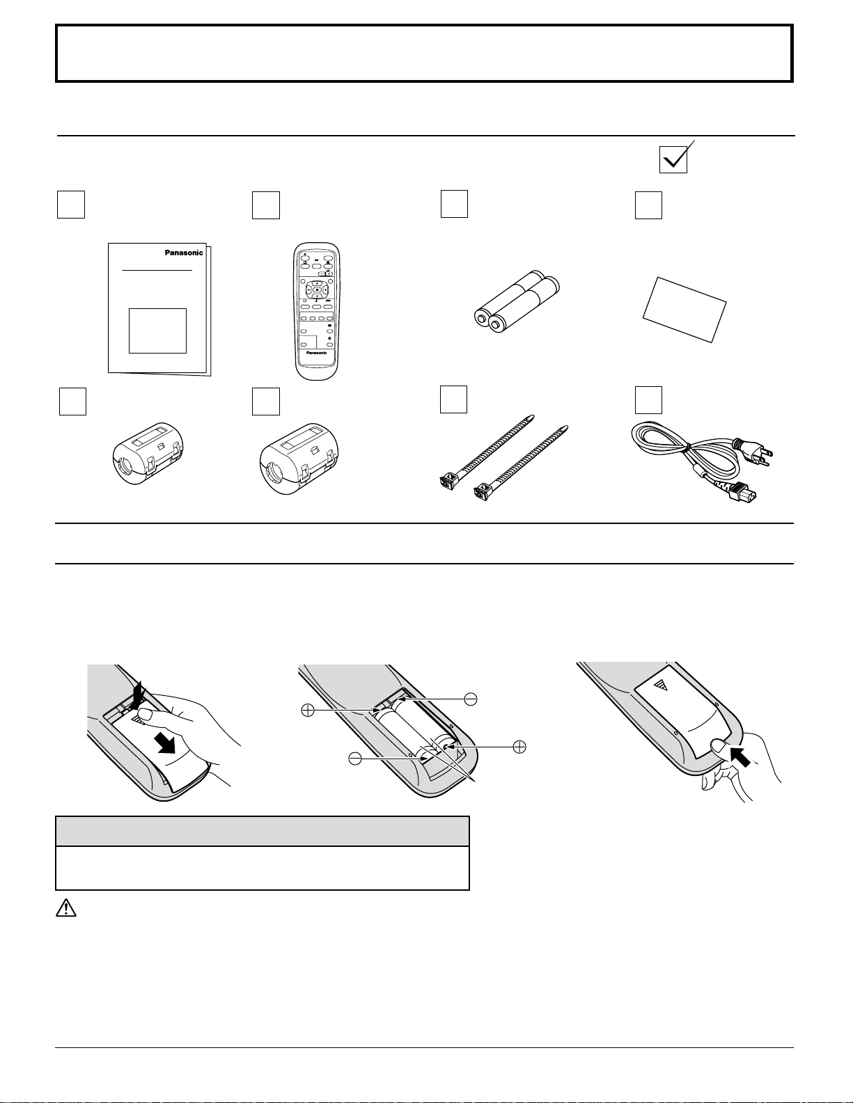
Accessories
Accessories Supplied
Check that you have the Accessories and items shown
Operating
Instruction book
Remote Control
Transmitter
EUR646529
INPUT
SURROUND
VOL
NR
PICTURE
SET UP
SOUND
ZOOM
MULTI
SWAP SELECT
MOVE
PIP
PICTURE
POS. /SIZE
ASPECT
OFF TIMER
PC
PLASMA DISPLAY
Ferrite core (small size) Ferrite core (large size)
Remote Control Batteries
Requires two AA batteries.
1. Turn the transmitter face down.
Press and slide off the battery
cover.
2. Install the batteries as shown in the
battery compartment.
(Polarity + or – must match the
markings in the compartment.)
Batteries for the Remote
Control Transmitter
(AA Battery × 2)
Fixing bands
3. Replace the cover and slide in
reverse until the lock snaps.
Warranty
AC cord
Two "AA" size
Helpful Hint:
For frequent remote control users, replace old batteries with
Alkaline batteries for longer life.
Precaution on battery use
Incorrect installation can cause battery leakage and corrosion that will damage the remote control transmitter.
Observe the following precautions:
1. Batteries should always be replaced as a pair. Always use new batteries when replacing the old set.
2. Do not combine a used battery with a new one.
3. Do not mix battery types (example: “Zinc Carbon” with “Alkaline”).
4. Do not attempt to charge, short-circuit, disassemble, heat or burn used batteries.
5. Battery replacement is necessary when the remote control acts sporadically or stops operating the Plasma Display.
8
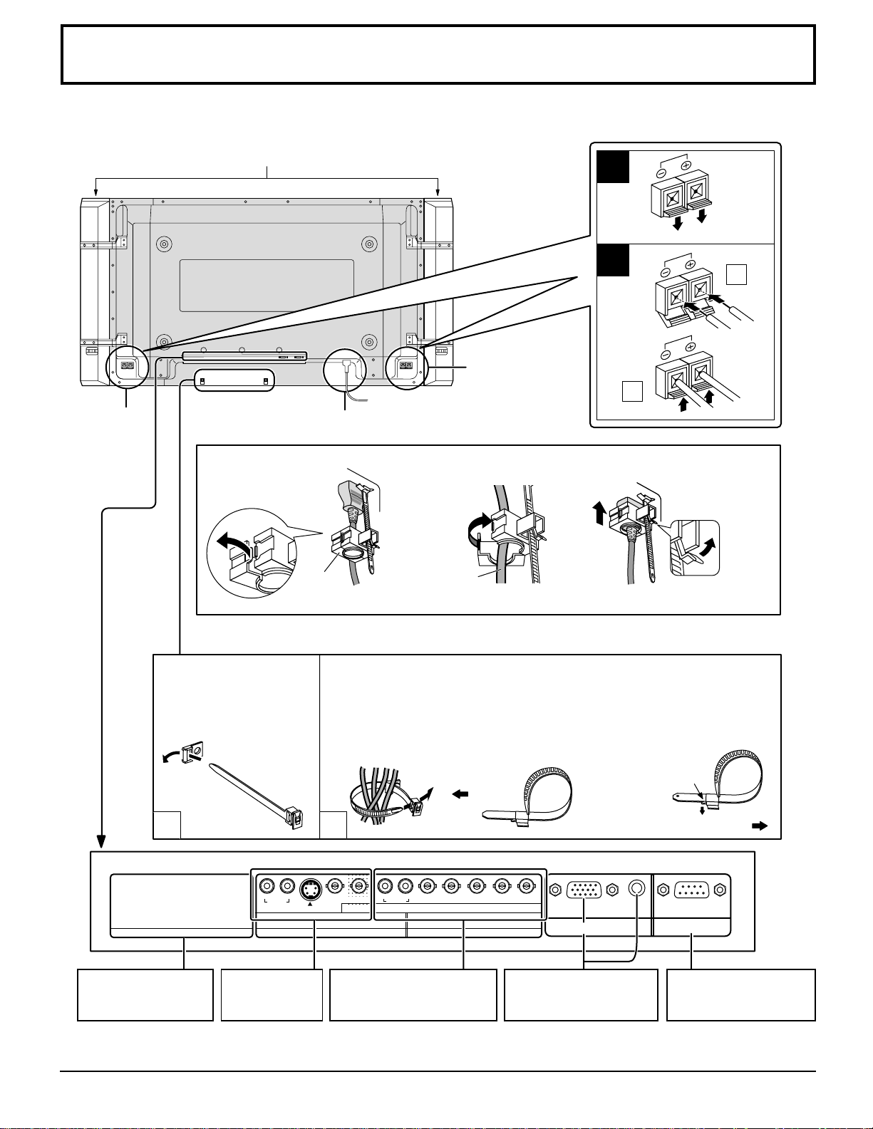
Connections
When connecting the speakers, be sure to use only the optional accessory speakers.
Refer to the speaker’s Installation Manual for details on speaker installation.
(Example : TH-42PWD6)
Speakers (Optional accessories)
1
SPEAKERS
Terminals (R)
AC cord connection (see page 13)
– AC cord fixing
1. Open the clamper.
2. Insert the AC cord and
close the clamper
securely.
Clamper
Note: The power plug in the illustration may not be the type fitted to your set.
AC cord
– Cable fixing bands
Secure any excess cables with bands as required.
Pass the attached
cable fixing band
through the clip as
shown in the figure.
To secure cables connected to Terminals, wrap the cable fixing band
around them then pass the pointed end through the locking block, as
shown in the figure.
While ensuring there is sufficient slack in cables to minimize stress
(especially in the power cord), firmly bind all cables with the
supplied fixing band.
SPEAKERS
Terminals (L)
To tighten:
Pull
2
1
2
3. Slide up the clamper and fix
the AC cord plug securely.
When loosen
the clamper:
To loosen:
Push the
catch
1
SLOT1
Optional Terminal
Board Insert Slot
(covered)
R AUDIO L
IN
A V Terminals
(see page12)
2
R AUDIO L
S VIDEO IN
AV
SLOT2 SLOT3
VIDEO OUT
VIDEO IN
COMPONENT/RGB IN
and Audio IN Terminals
(see page12)
VD HD
COMPONENT/RGB IN
PR/CR/R PB/CB/B
Y/G
From EXTERNAL
monitor terminal on
Computer (see page 10)
Note: At factory shipment, Terminal boards are installed in SLOT 2 and SLOT 3.
TH-37PWD6 has 2 SLOTs only.
Pull
AUDIO
SERIALPC IN
From SERIAL
Terminal on Computer
(see page 11)
9
Connections
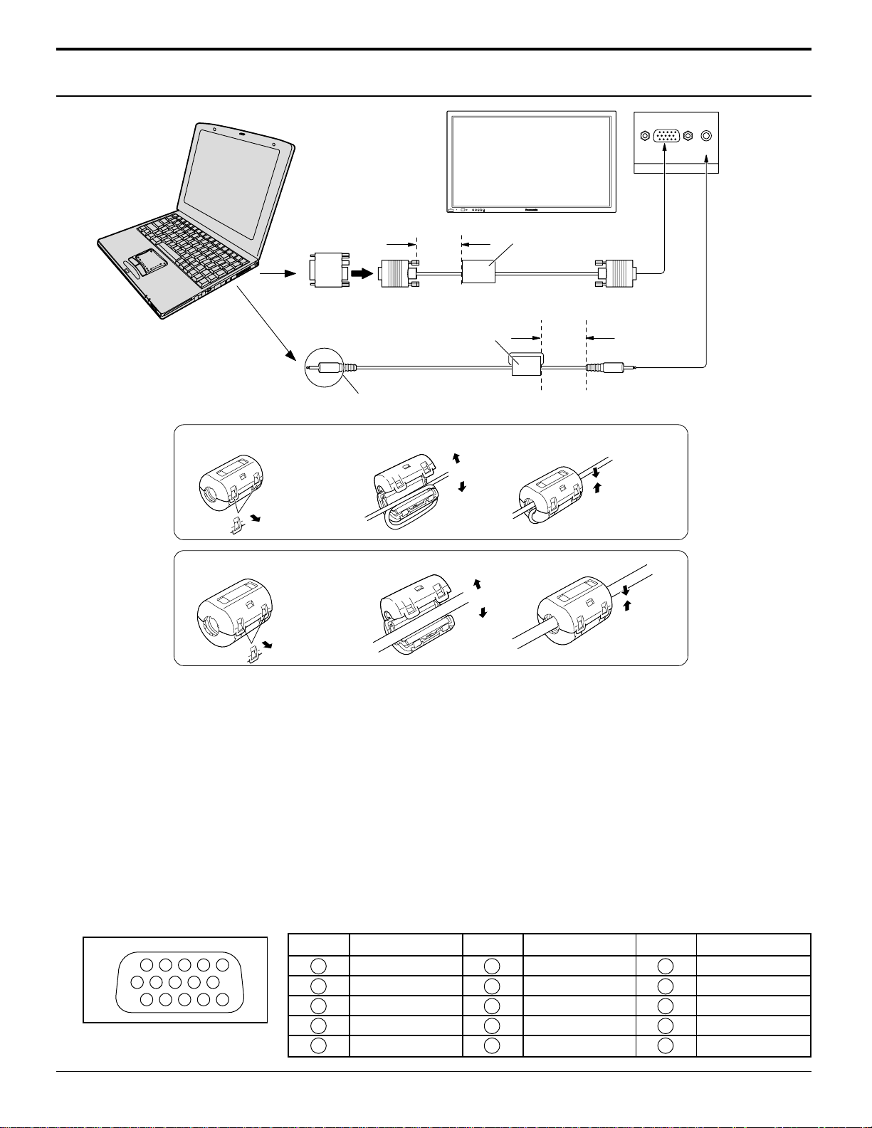
PC Input Terminals connection
COMPUTER
INPUTMENU ENTER
R - STANDBY
G POWER ON
Conversion adapter
(if necessary)
Connect a cable which matches
the audio output terminal on the computer.
Installing the ferrite core (Small size)
1
2
Less than
15
3"
/
16
(10 cm)
Ferrite core (small size)
Audio
(supplied)
Open
VOL
– +
Ferrite core (large size)
(supplied)
RGB
PC cable
Less than
15
3"
(10 cm)
3
D-sub 15p
/
16
Stereo plug
AUDIO
PC IN
Pull back the tabs
(in two places)
Installing the ferrite core (Large size)
1
Pull back the tabs
(in two places)
2
3
Open
Press the cable
through and close
Press the cable
through and close
Notes:
(1) Computer signals which can be input are those with a horizontal scanning frequency of 15 to 110 kHz and vertical
scanning frequency of 48 to 120 Hz. (However , the image will not be displayed properly if the signals exceed 1,200 lines.)
(2) The display resolution is a maximum of 640 × 480 dots (TH-37PWD6, TH-42PWD6), 768 × 768 dots (TH-42PHD6),
1,024 × 768 dots (TH-50PHD6) when the aspect mode is set to “4:3”, and 852 × 480 dots (TH-37PWD6, TH-42PWD6),
1,024 × 768 dots (TH-42PHD6), 1,366 × 768 dots (TH-50PHD6) when the aspect mode is set to “16:9”. If the display
resolution exceeds these maximums, it may not be possible to show fine detail with sufficient clarity.
(3) The PC input terminals are DDC1/2B-compatible. If the computer being connected is not DDC1/2B-compatible, you will
need to make setting changes to the computer at the time of connection.
(4) Some PC models cannot be connected to the set.
(5) There is no need to use an adapter for computers with DOS/V compatible D-sub 15P terminal.
(6) The computer shown in the illustration is for example purposes only.
(7) Additional equipment and cables shown are not supplied with this set.
(8) Do not set the horizontal and vertical scanning frequencies for PC signals which are above or below the specified
frequency range.
(9) Component Input is possible with the pin 1,2,3 of the D-sub 15P Connector.
Signal Names for D-sub 15P Connector
Pin No.
1514131211
67839
1
2
10
45
Pin Layout for PC Input
Terminal
10
Signal Name
1
2
3
4
5
R (PR/CR)
G(Y)
B(PB/CB)
GND (Ground)
GND (Ground)
Pin No.
6
7
8
9
10
Signal Name
GND (Ground)
GND (Ground)
GND (Ground)
NC (not connected)
GND (Ground)
Pin No.
11
12
13
14
15
Signal Name
GND (Ground)
SDA
HD/SYNC
VD
SCL
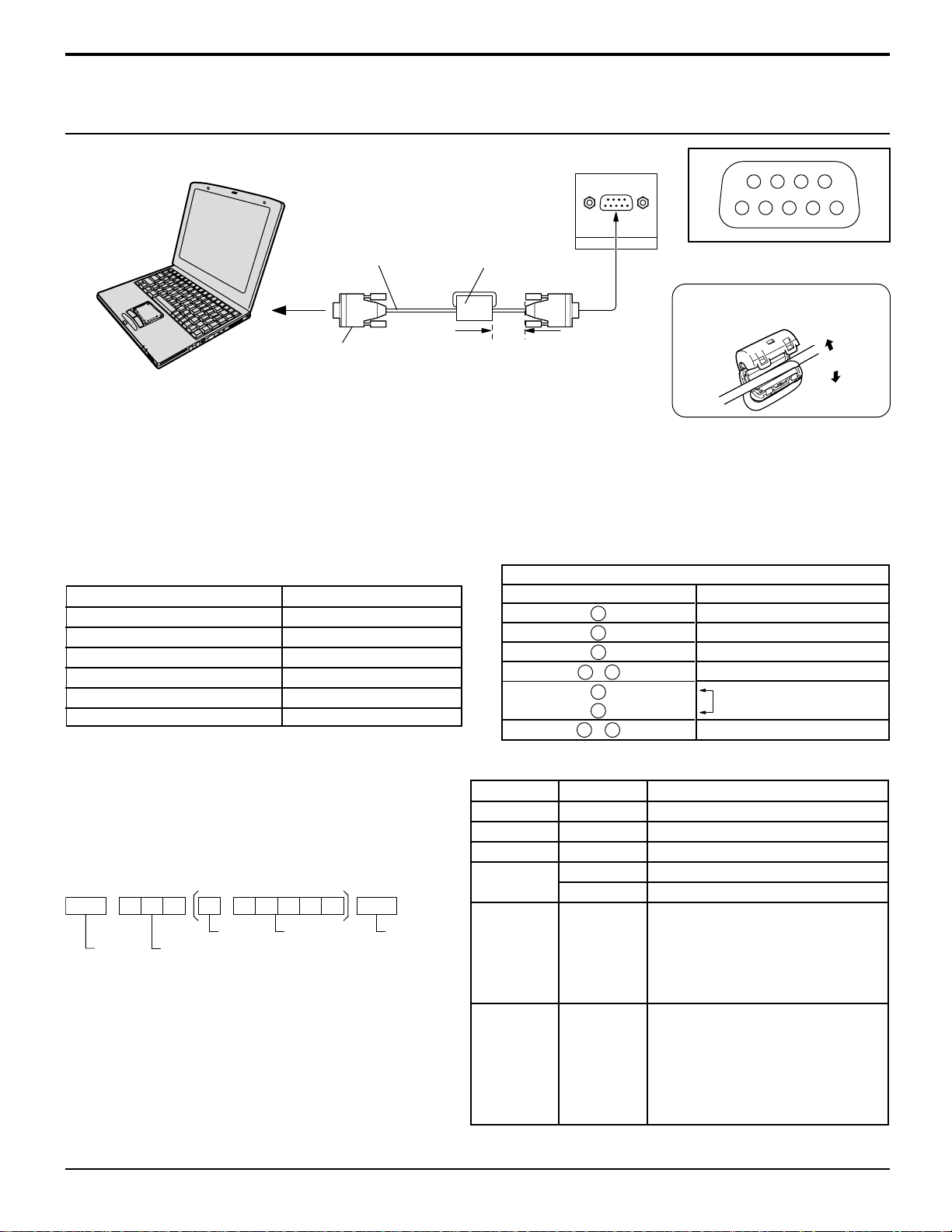
Connections
SERIAL Terminals connection
The SERIAL terminal is used when the Plasma Display is controlled by a computer.
COMPUTER
RS-232C
Straight cable
Ferrite core
(large size)
(supplied)
SERIAL
Pin layout for RS-232C
Installing the ferrite core
(Large size)
D-sub 9p
Less than
15
3"
/16
(10 cm)
Notes:
(1) Use the RS-232C cable to connect the computer to the Plasma Display.
(2) The computer shown is for example purposes only.
(3) Additional equipment and cables shown are not supplied with this set.
The SERIAL terminal conforms to the RS-232C interface specification, so that the Plasma Display can be controlled by a
computer which is connected to this terminal.
The computer will require software which allows the sending and receiving of control data which satisfies the conditions
given below. Use a computer application such as programming language software. Refer to the documentation for the
computer application for details.
9876
53214
Open
Communication parameters
Signal level
Synchronization method
Baud rate
Parity
Character length
Stop bit
Flow control
RS-232C compliant
Asynchronous
9600 bps
None
8 bits
1 bit
–
Basic format for control data
The transmission of control data from the computer starts
with a STX signal, followed by the command, the
parameters, and lastly an ETX signal in that order. If there
are no parameters, then the parameter signal does not need
to be sent.
STX
Start
(02h)
Colon Parameter(s)
3-character
command (3 bytes)
(1 - 5 bytes)
ETX:C2C1 C3 P2P1 P3 P4 P5
End
(03h)
Notes:
(1) If multiple commands are transmitted, be sure to wait
for the response for the first command to come from
this unit before sending the next command.
(2) If an incorrect command is sent by mistake, this unit will
send an “ER401” command back to the computer.
With the power off, this display responds to PON command only.
Command
Command
PON
POF
AVL
AMT
IMS
DAM
RS-232C Conversion cable
D-sub 9-pin female
2
3
5
4 • 6
7
8
1 • 9
Parameter
None
None
**
0
1
None
SL1
SL2
SL3
PC1
None
NORM
ZOOM
FULL
JUST
SELF
Details
R X D
T X D
GND
Non use
Shorted
NC
Control details
Power ON
Power OFF
Volume 00 - 63
Audio MUTE OFF
Audio MUTE ON
Input select (toggle)
Slot1 input
Slot2 input
Slot3 input
PC input
Screen mode select (toggle)
NORMAL (4:3)
ZOOM
FULL
JUST
Panasonic AUTO
11
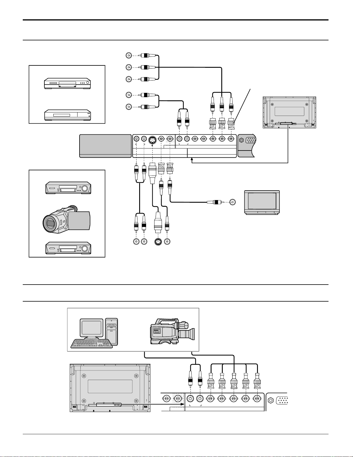
Connections
AV & COMPONENT Connection
COMPONENT VIDEO OUT
R
R
Example of input signal source
DVD
Digital TV-SET-TOP-BOX
(DTV-STB)
SLOT1
Example of input signal source
S VIDEO VCR
CAMCORDER
Y, PB, PR,
OUT
AUDIO
OUT
P
Y
L
R
B
R AUDIO L
IN
R AUDIO L
S VIDEO IN
AV
SLOT2 SLOT3
VIDEO OUT
VIDEO IN
VD HD
COMPONENT/RGB IN
PR/CR/R PB/CB/B
RCA-BNC
adapter
plug
AUDIO
Y/G
PC IN
MONITOR
VIDEO IN
VCR
L
R
AUDIO
OUT
S VIDEO
OUT
VIDEO
OUT
Notes:
(1) Change the “Component/RGB-in” setting in the “Setup” menu to “Component”. (see page 33)
(2) Additional equipment, cables and adapter plugs shown are not supplied with this set.
RGB signal (R, G, B, HD, VD)
Computer
or
Notes:
(1) Change the “Component/RGB-in” setting in the “Setup” menu to “RGB”. (see page 33)
(2) Additional equipment, cables and adapter plugs shown are not supplied with this set.
RGB Camcorder
R AUDIO L
VIDEO OUT
VIDEO IN
AV
VD HD
COMPONENT/RGB IN
PR/CR/R PB/CB/B
Y/G
12
 Loading...