

Panasonic TG2323AG Service Manual
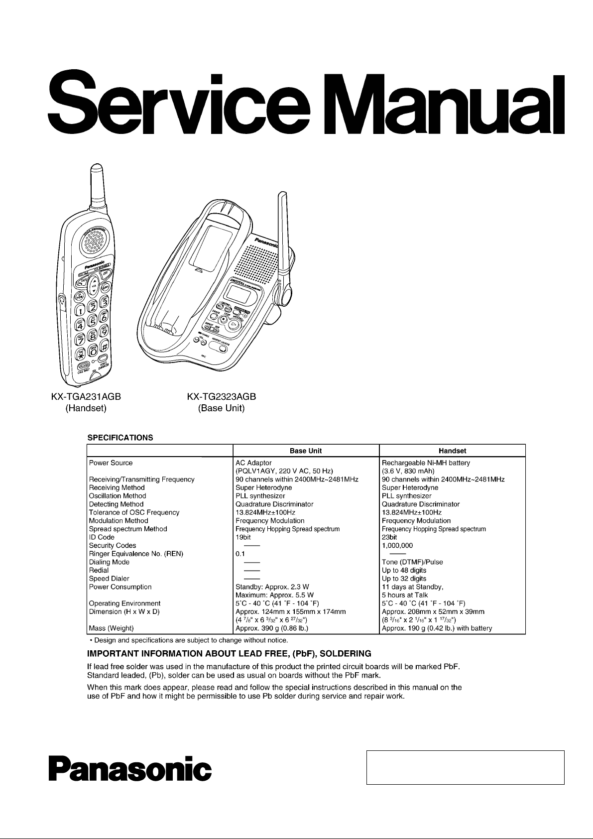
ORDER NO. KM40501578CE
Telephone Equipment
KX-TG2323AGB
KX-TGA231AGB
2.4GHz Digital Cordless Answering
System
Black Version
(for Argentina)
© 2005 Panasonic Communications Co., Ltd. All
rights reserved. Unauthorized copying and
distribution is a violation of law.
KX-TG2323AGB / KX-TGA231AGB
Note:
Because CONTENTS 4 to 9 are the extracts from the Operating Instructions of this model, they are subject to change without
notice. Please refer to the original Operating Instructions for further information.
CONTENTS
Page Page
1 ABOUT LEAD FREE SOLDER (PbF: Pb free) 4
1.1. Suggested PbF Solder
1.2. How to Recognize that Pb Free Solder is Used
2 FOR SERVICE TECHNICIANS
3 CAUTION
4 BATTERY
4.1. Battery Charge
4.2. Battery Recharge
4.3. Battery Information
4.4. Battery Replacement
5 LOCATION OF CONTROLS
5.1. Base Unit
5.2. Handset
6 DISPLAY
6.1. Base Unit Display
7 SETTINGS
7.1. Connections
7.2. Connecting an Optional Headset
7.3. Time and Day
7.4. Dialing Mode
7.5. Voice Enhancer Technology
7.6. Ringer Tone
8 OPERATION
8.1. Answering System
8.2. For Call Waiting Service Users
8.3. FLASH Button
8.4. Remote Operation from a Touch Tone Phone
9 TROUBLESHOOTING
10 DISASSEMBLY INSTRUCTIONS
10.1. Base Unit
10.2. Handset
11 TROUBLESHOOTING GUIDE
11.1. Check Power
11.2. Error Message Table
11.3. Check Record
11.4. Check Playback
11.5. Check Battery Charge
10
11
11
12
12
13
13
14
14
14
15
15
17
18
18
22
25
25
26
27
28
28
29
30
30
4
5
6
6
7
7
7
7
8
9
9
11.6. Check Link
11.7. Check the RF Part
11.8. Check Handset Transmission
11.9. Check Handset Reception
12 TEST MODE
12.1. Test Mode Flow Chart for Base Unit
12.2. Test Mode Flow Chart for Handset
12.3. X801 (Base Unit), X201 (Handset) Check
12.4. Adjust Battery Low Detector Voltage (Handset)
12.5. Base Unit Reference Drawing
12.6. Handset Reference Drawing
12.7. Frequency Table
12.8. How to Clear User Setting
13 DESCRIPTION
13.1. Frequency
13.2. FHSS (Frequency Hopping Spread Spectrum)
13.3. Signal Flowchart in the Whole System
14 EXPLANATION OF LINK DATA COMMUNICATION
14.1. Calling
14.2. To Terminate Communication
14.3. Ringing
15 B LOCK DIAGRAM (Base Unit)
16 CIRCUIT OPERATION (Base Unit)
16.1. DSP (Digital Speech/Signal Processing: IC501)
16.2. Flash Memory (IC701)
16.3. Power Supply Circuit
16.4. Reset Circuit
16.5. Locator Mode
16.6. Telephone Line Interface
16.7. Auto Disconnect Circuit
16.8. Parallel Connection Detect Circuit
17 B LOCK DIAGRAM (Handset)
18 CIRCUIT OPERATION (Handset)
18.1. Construction
18.2. Power Supply Circuit
18.3. Charge Circuit
18.4. Ringer and Handset SP-Phone
31
32
36
36
37
37
40
44
44
45
47
48
49
50
50
50
52
53
53
53
53
54
55
55
56
56
58
59
59
60
61
62
63
63
64
65
65
2
KX-TG2323AGB / KX-TGA231AGB
18.5. Sending Signal 66
18.6. Reception Signal
19 SIGNAL ROUTE
20 CPU DATA (Base Unit)
20.1. IC501
21 CPU DATA (Handset)
21.1. IC201
22 EXPLANATION OF IC TERMINALS (RF Unit)
22.1. IC901
23 HOW TO REPLACE A FLAT PACKAGE IC
23.1. Preparation
23.2. Procedure
23.3. Removing Solder from Between Pins
24 CABINET AND ELECTRICAL PARTS (Base Unit)
25 CABINET AND ELECTRICAL PARTS (Handset)
26 ACCESSORIES AND PACKING MATERIALS
27 TER MINAL GUIDE OF THE ICs, TRANSISTORS AND DIODES
27.1. Base Unit
27.2. Handset
66
28 REPLACEMENT PARTS LIST
67
68
68
69
69
70
70
71
71
71
71
72
73
74
28.1. Base Unit
28.2. Handset
28.3. Accessories and Packing Materials
29 FOR SCHEMATIC DIAGRAM
29.1. Base Unit (SCHEMATIC DIAGRAM (Base Unit))
29.2. Handset (SCHEMATIC DIAGRAM (Handset))
30 SCHEMATIC DIAGRAM (Base Unit)
30.1. Main
30.2. Operation
31 SCHEMATIC DIAGRAM (Handset)
32 SC HEMATIC DIAGRAM (RF PART)
33 CIRCUIT BOARD (BASE UNIT)
33.1. Main
33.2. Operation
34 CIRCUIT BOARD (HANDSET)
75
75
34.1. Component View
34.2. Flow Solder Side View
75
76
76
78
80
81
81
81
82
82
84
86
88
89
89
91
93
93
94
3
KX-TG2323AGB / KX-TGA231AGB
1 ABOUT LEAD FREE SOLDER (PbF: Pb free)
Note:
In the information below, Pb, the symbol for lead in the periodic table of elements, will refer to standard solder or solder that
contains lead.
We will use PbF solder when discussing the lead free solder used in our manufacturing process which is made from Tin (Sn),
Silver (Ag), and Copper (Cu).
This model, and others like it, manufactured using lead free solder will have PbF stamped on the PCB. For service and repair
work we suggest using the same type of solder although, with some precautions, standard Pb solder can also be used.
Caution
•
• PbF solder has a melting point that is 50°F ~70°F (30°C ~ 40°C) higher than Pb solder. Please use a soldering iron with
• •
temperature control and adjust it to 700°F ± 20°F (370°C ± 10°C). In case of using high temperature soldering iron, please
be careful not to heat too long.
•
• PbF solder will tend to splash if it is heated much higher than its melting point, approximately 1100°F (600°C).
• •
•
• If you must use Pb solder on a PCB manufactured using PbF solder, remove as much of the original PbF solder as possible
• •
and be sure that any remaining is melted prior to applying the Pb solder.
•
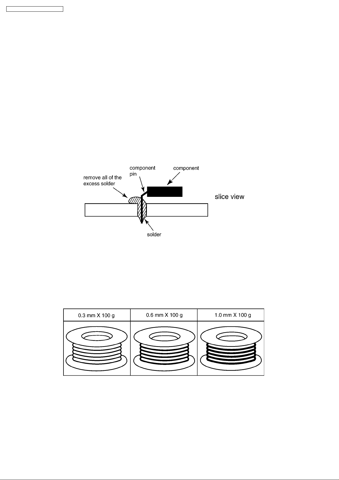
• When applying PbF solder to double layered boards, please check the component side for excess which may flow onto the
• •
opposite side (See the figure below).
1.1. Suggested PbF Solder
There are several types of PbF solder available commercially. While this product is manufactured using Tin, Silver, and Copper
(Sn+Ag+Cu), you can also use Tin and Copper (Sn+Cu) or Tin, Zinc, and Bismuth (Sn+Zn+Bi). Please check the
manufacturer’s specific instructions for the melting points of their products and any precautions for using their product with other
materials.
The following lead free (PbF) solder wire sizes are recommended for service of this product: 0.3 mm, 0.6 mm and 1.0 mm.
4
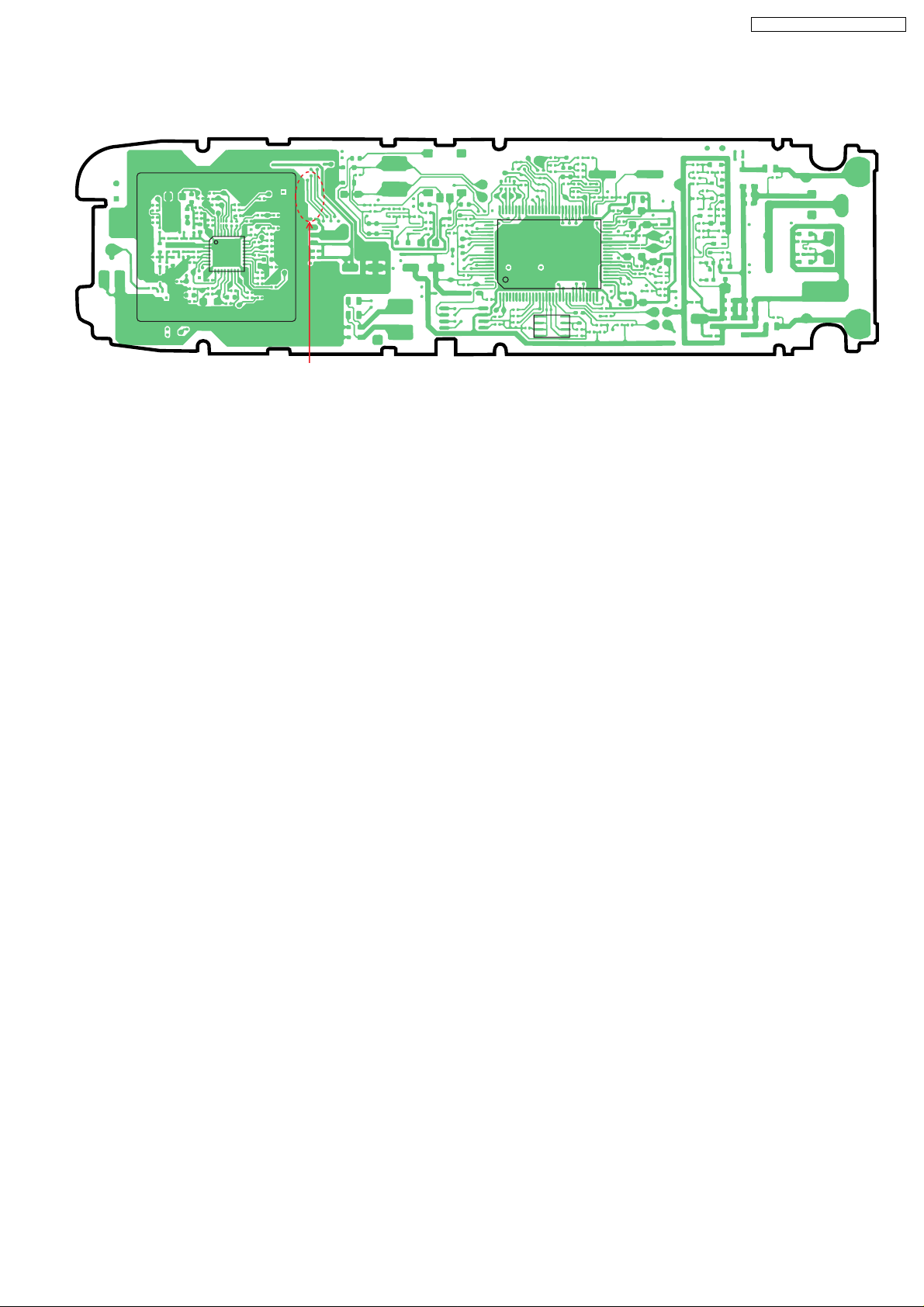
1.2. How to Recognize that Pb Free Solder is Used
(Example: Handset P.C.B.)
PbF
KX-TG2323AGB / KX-TGA231AGB
IC901
Marked
(Component View)
Note:
The location of the “PbF” mark is subject to change without notice.
IC201
IC202
5

KX-TG2323AGB / KX-TGA231AGB
2 FOR SERVICE TECHNICIANS
ICs and LSIs are vulnerable to static electricity.
When repairing, the following precautions will help prevent recurring malfunctions.
1. Cover plastic parts boxes with aluminum foil.
2. Ground the soldering irons.
3. Use a conductive mat on worktable.
4. Do not grasp IC or LSI pins with bare fingers.
3 CAUTION
Danger of explosion if battery is incorrectly replaced. Replace only with the same or equivalent type recommended by the
manufacturer.
Dispose of used batteries according to the manufacturer´s Instructions.
6
4 BATTERY
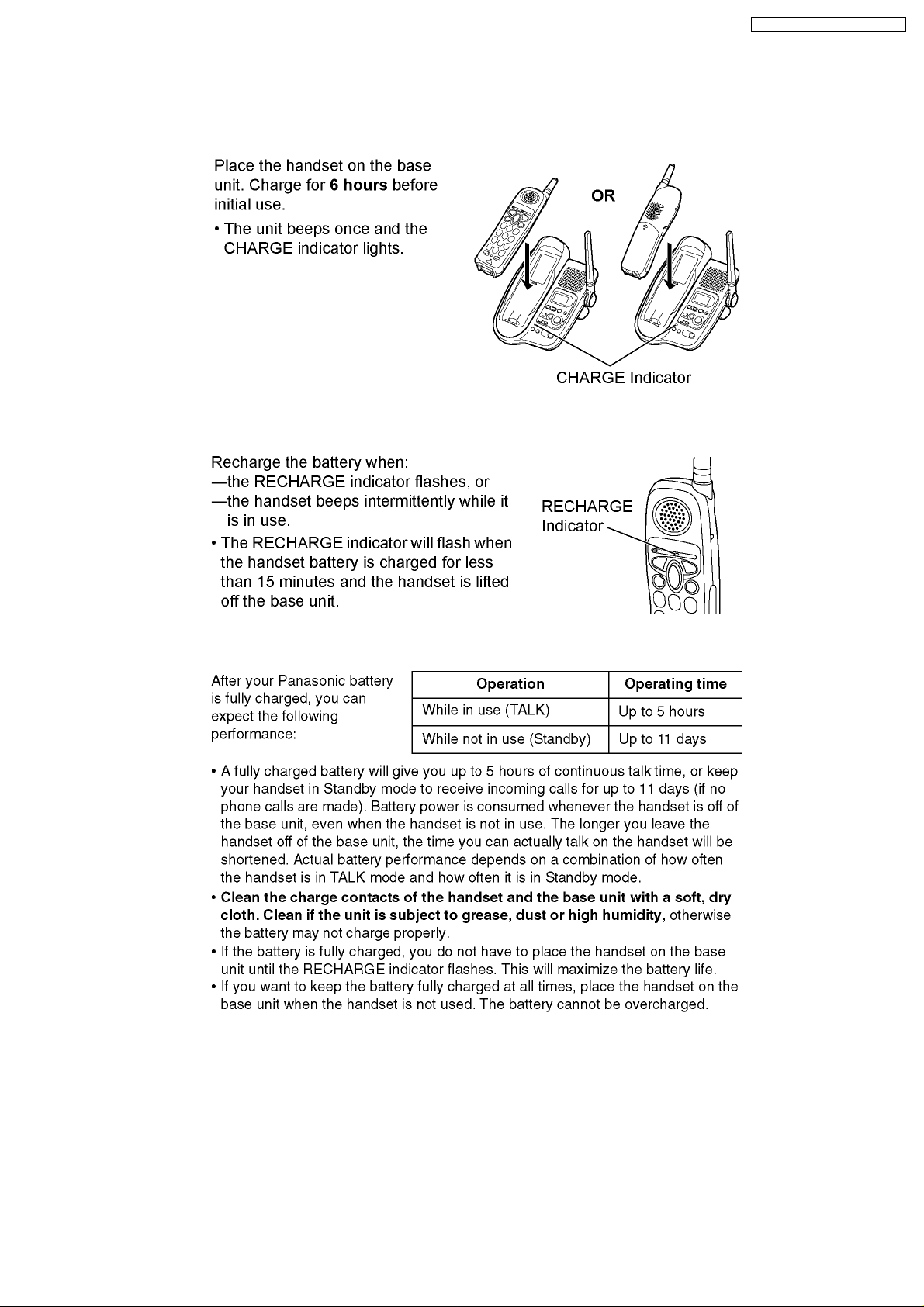
4.1. Battery Charge
4.2. Battery Recharge
KX-TG2323AGB / KX-TGA231AGB
4.3. Battery Information
7
KX-TG2323AGB / KX-TGA231AGB
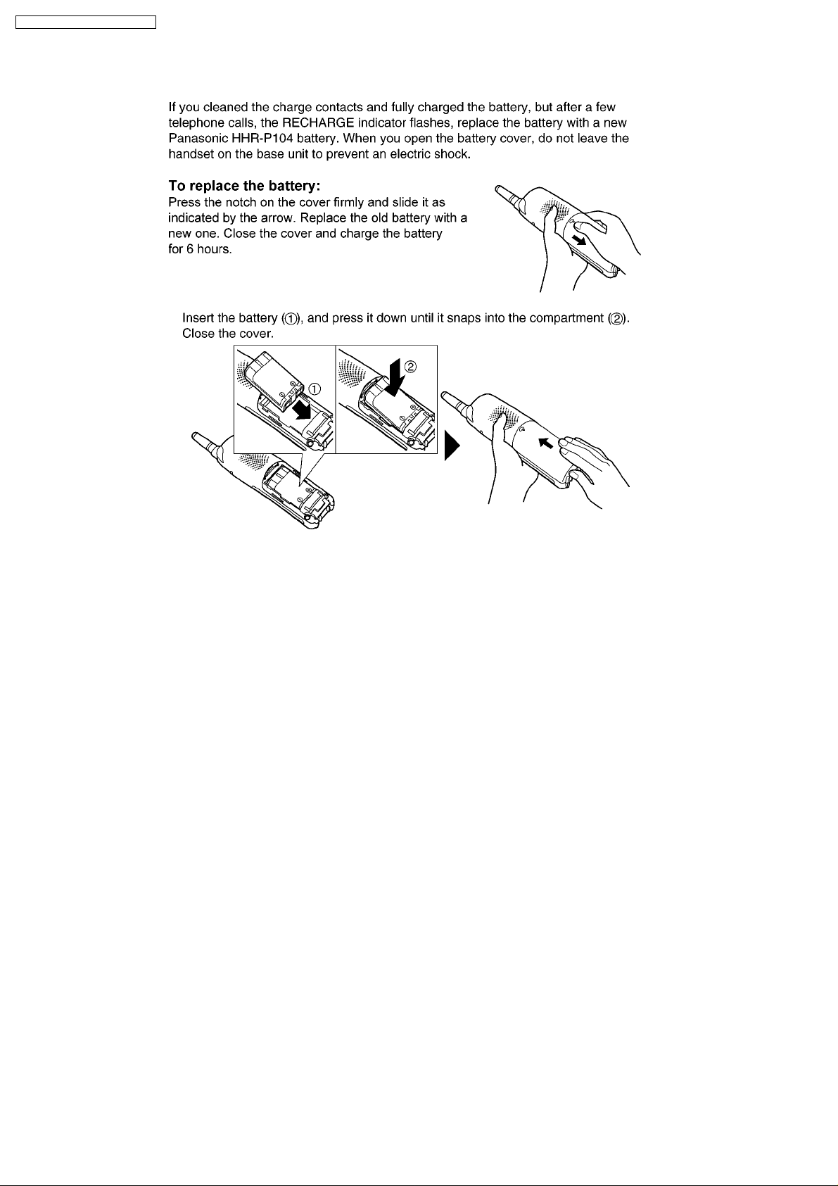
4.4. Battery Replacement
8
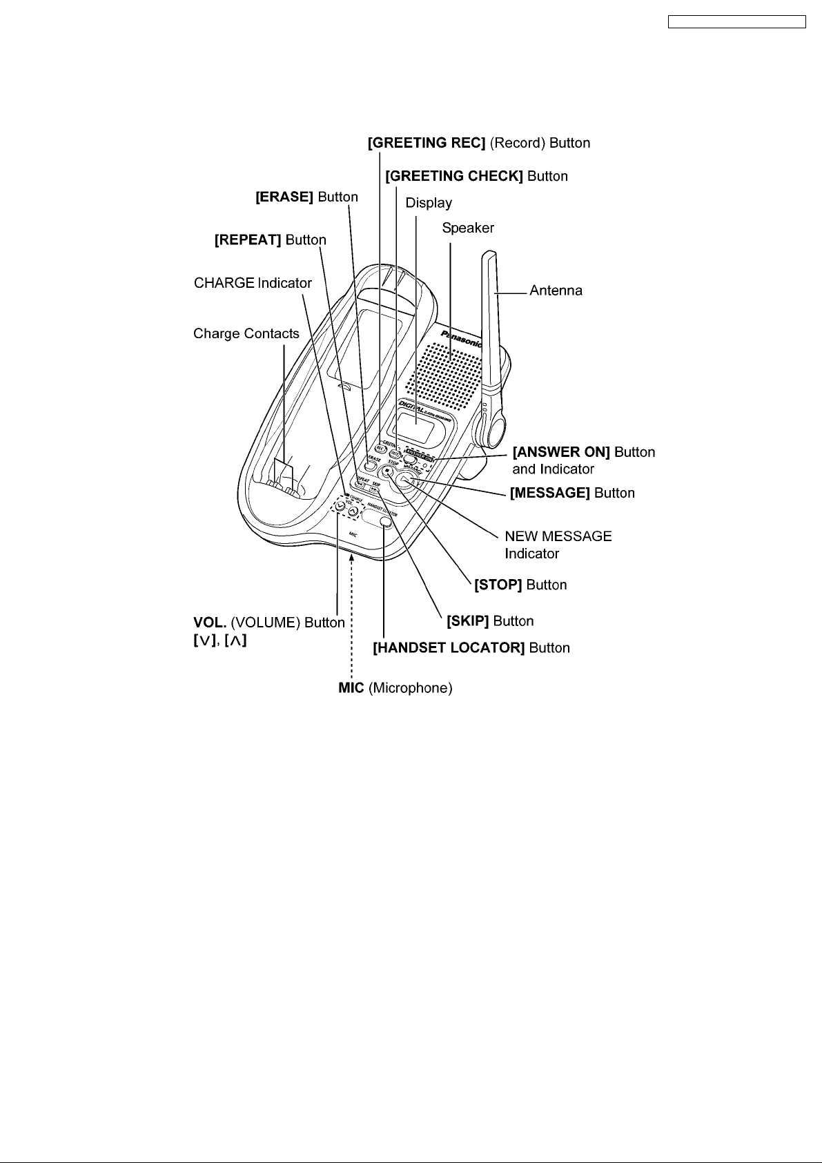
5 LOCATION OF CONTROLS
5.1. Base Unit
KX-TG2323AGB / KX-TGA231AGB
9
KX-TG2323AGB / KX-TGA231AGB
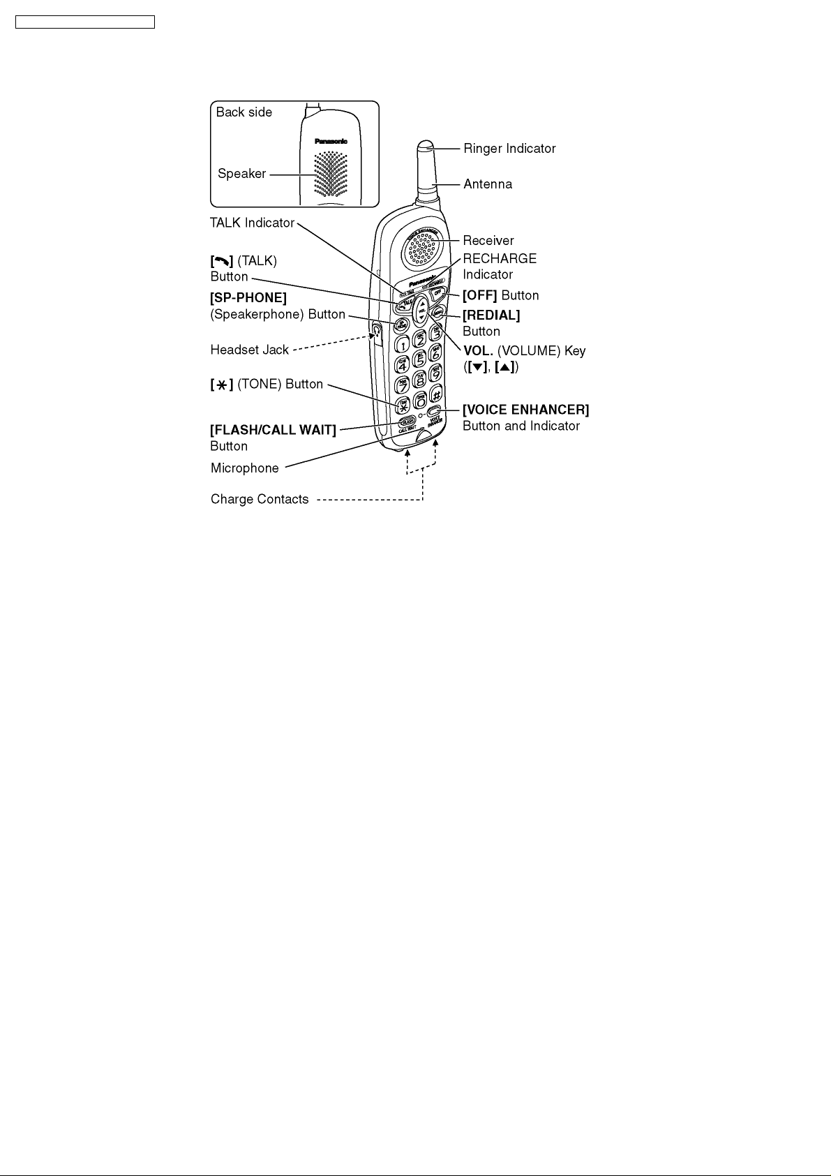
5.2. Handset
10
6 DISPLAY
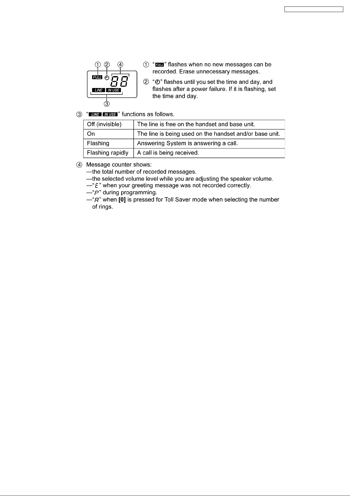
6.1. Base Unit Display
KX-TG2323AGB / KX-TGA231AGB
11
KX-TG2323AGB / KX-TGA231AGB
7 SETTINGS
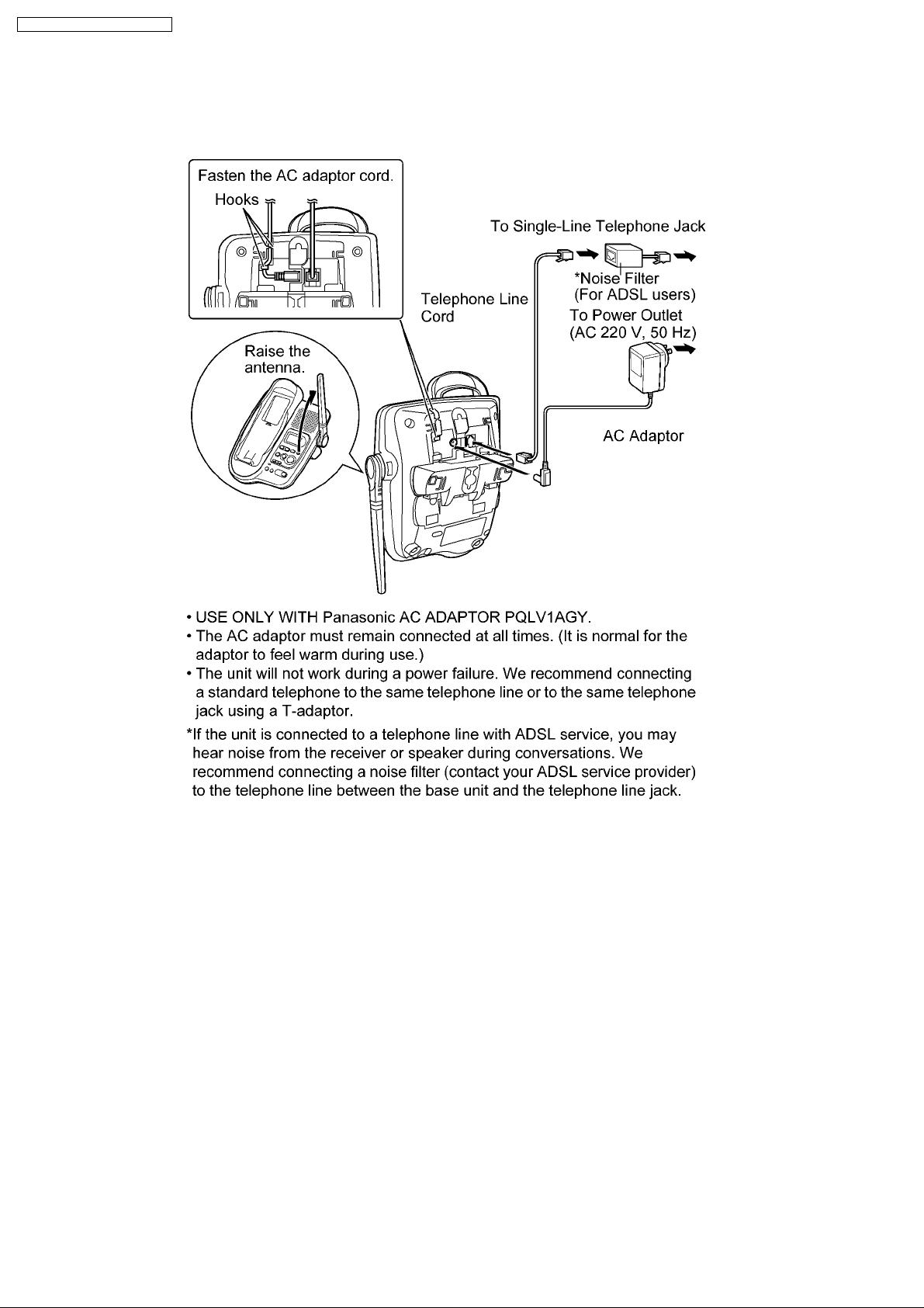
7.1. Connections
12
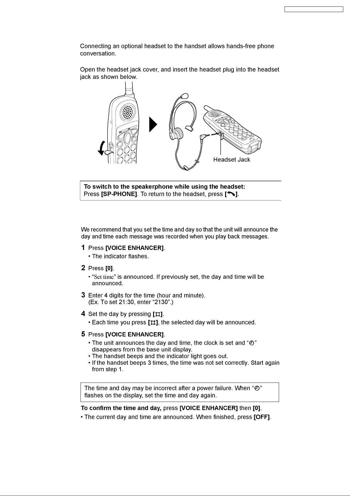
7.2. Connecting an Optional Headset
KX-TG2323AGB / KX-TGA231AGB
7.3. Time and Day
13
KX-TG2323AGB / KX-TGA231AGB
7.4. Dialing Mode
7.5. Voice Enhancer Technology
7.6. Ringer Tone
14
8 OPERATION
8.1. Answering System
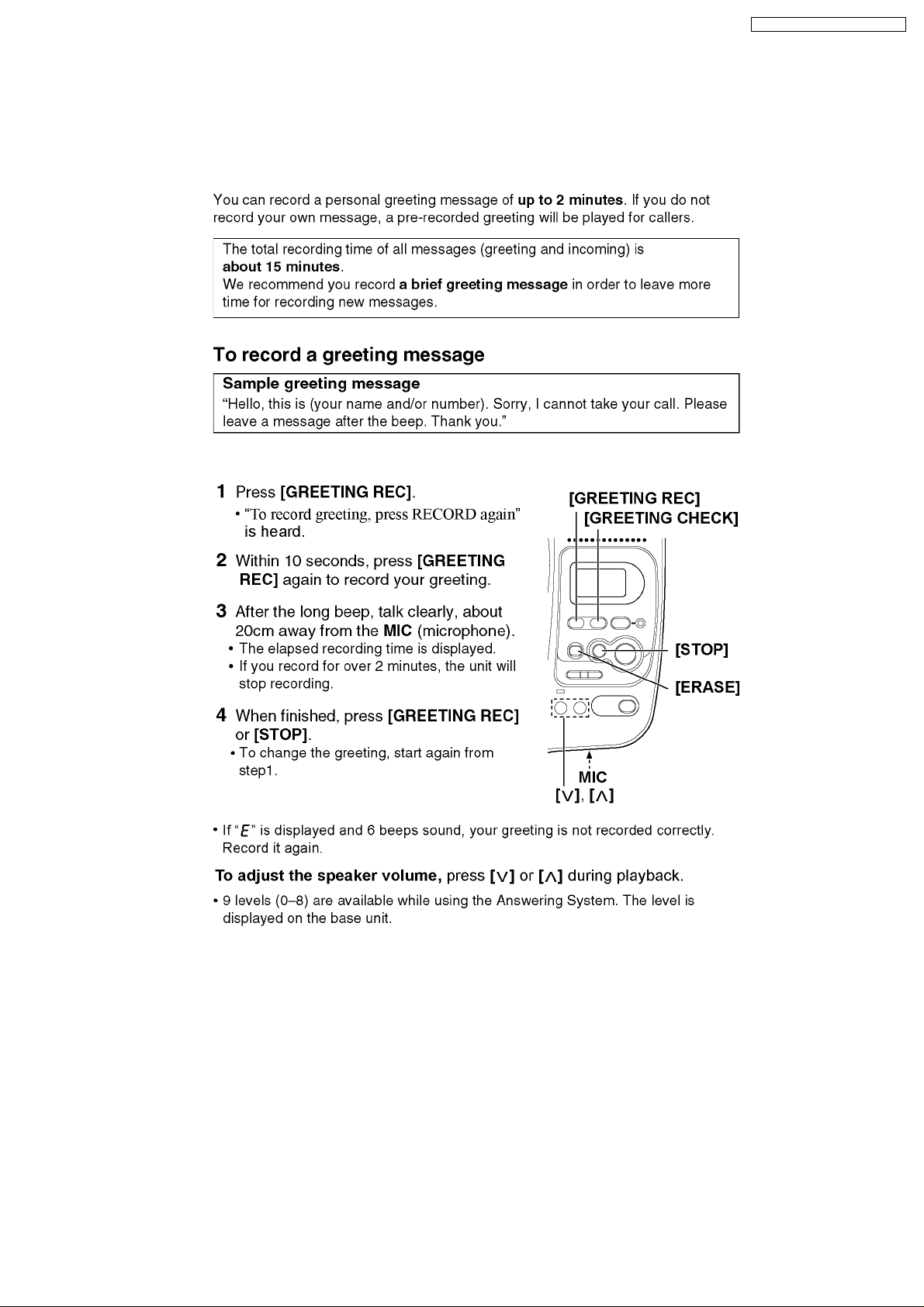
8.1.1. Greeting Message
KX-TG2323AGB / KX-TGA231AGB
15
 Loading...