

Panasonic Television User Manual

Panasonic Service and Technology Company
Technical Guide
th
10
Generation Plasma Display Television
National Training
Panasonic Service and Technology Company
Prepared by
Cesar Perdomo and Jean Magloire
Panasonic Service and Technology Company
National Training
Copyright © 2007 by Panasonic Services Company
All rights reserved. Unauthorized copying and distribution is a violation of law.
Warning
This service information is designed for experienced repair technicians only and is not designed for use by the
general public. It does not contain warnings or cautions to advise non-technical individuals of potential dangers
in attempting to service a product. Products powered by electricity should be serviced or repaired only by
experienced professional technicians. Any attempt to service or repair the product or products dealt with in this
service information by anyone else could result in serious injury or death.
Table of Contents
Subject Page # Subject Page #
2007 Panasonic Plasma Line-up
Models Comparison
High Resolution (FULL-HD Panel)
TH-42PX75U Board Layout & Description
TH-42PX75U Board Layout (Pictorial)
2006/2007 Signal Process/Switching Circuit
Overall Block Diagram
Standby Circuit
STB5V/STB3.3V Distribution
Main CPU VCC Supply (A Board)
TV_SUB_ON/TUNER_SUB_ON
TV_SUB_ON (F_STB_ON)
TV_SUB_ON (Relay Drive Circuit)
PFC Circuit
5
6
9
13
14
15
16
21
25
28
30
32
34
36
Troubleshooting (No Power/Dead Unit) Part 2
SOS Circuit Overview
DRV_RST SOS
Location of Q9302
Close-up View of Q9302
5 Blinks SOS (1)
SOS (Drive-reset)
D & C Boards Connection
12 Blinks SOS
Signal Circuit Overview
Video Process Block Diagram
D Board Block Diagram
Panel Drive (TH-42PX75U)
Audio Process Block Diagram
56
59
62
63
64
66
68
69
70
75
77
79
81
83
ACFB (Active Clamp Full Bridge Switching) Circuit
MAIN/SUB Voltages
F+15V, DTV9V, SUB5V SOS Detect Circuit
Power On Operation
P15V/P5V Circuit
Vsus/Vda Circuit
Troubleshooting (No Power/Dead Unit) Part 1
37
39
41
43
51
53
55
Self-Check Function
How to Reset the Unit
Self-Check Menu
Check point
Serviceman Mode
Serviceman Mode Menu and Navigation
Internal Test Patterns
3
88
89
90
91
92
93
95
Table of Contents (Continued)
Subject Page #
Driver Setup Adjustment 96
Initialization Pulse Adjustment 97
Quick adjustment after P.C.B. exchange 98
4

2007 Panasonic Plasma Line-up
5

Models Comparison
6

Models Comparison
7

Models Comparison
8
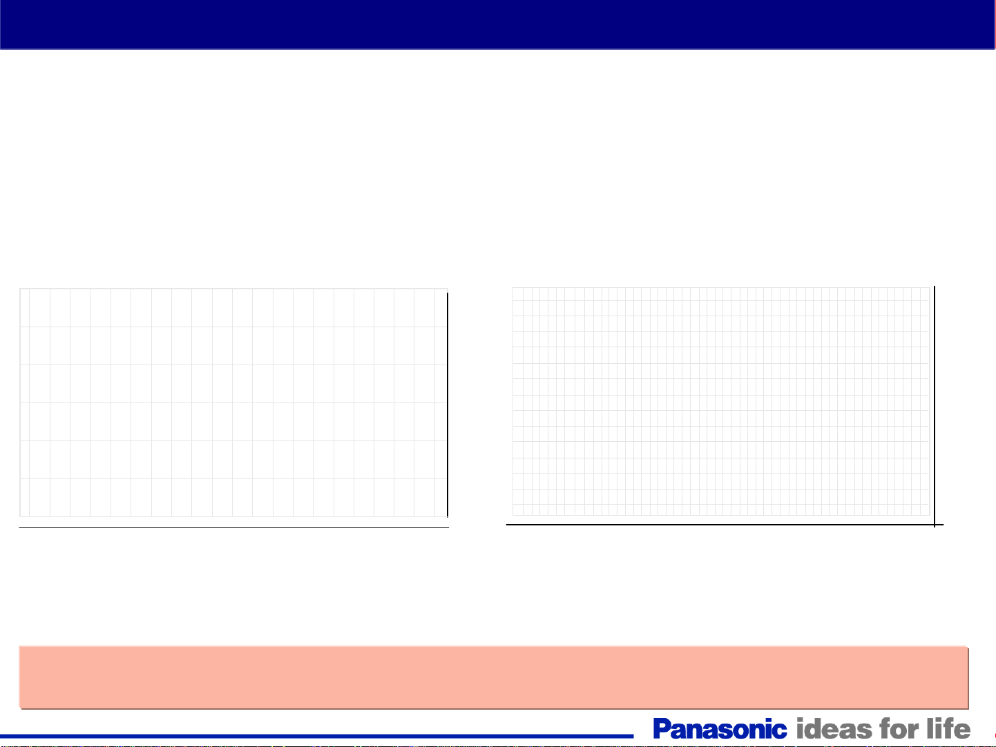
High Resolution (FULL-HD Panel)
The Full-HD plasma panel boasts a total of about 2,070,000 pixels (1920 x 1080).
It renders true-to-life HD images with about twice the resolution of a standard HD panel.
HD PDP
(approx. 1,050,000 pixels)
(approx. 2,070,000 pixels)
●
Full-HD PDP
●
1080
768
●
1366
(Image resolution about twice as high)
●
●
● ●
1920
*When compared to the 50PX600
●
About Twice the Resolution of a Standard HD PDP!
About Twice the Resolution of a Standard HD PDP!
9

10

10
th
Generation Plasma Television
Board Layout
11

12
TH-42PX75U Boards Layout & Description
Panasonic started using single scan addressing in the 42” HD models last year when the 9th generation
of Plasma TV was introduced. The single scan addressing was only used on standard definition models
previously. For this generation, Panasonic has added the 50” models to the list of TV using single scan
addressing.
13
TH-42PX75U Board Layout (Pictorial)
14

2006/2007 Signal Process/Switching Circuit
The 2007 42” plasma models
have less boards than the
previous generation. The PA,
DT, DG, H, and HC boards used
on the 2006 42” models are now
incorporated within the new A
board of the 2007 models.
15

Overall Block Diagram
16

Overall Block Diagram
The operation of the plasma TV can be divided into 3 different sections:
1. Power Supply Circuit
The power supply circuit board (P board) provides voltages to the Signal switching/processing circuit
and the Panel drive circuit.
2. Signal Switching/Processing Circuit
Upon connecting the unit to the AC voltage source, the STB5V of the P board is provided to the A board
for system control operation. The F_STB15V is also provided to the signal switching/processing circuit
of the A board. It remains present for approximately 25 seconds unless the power button is pressed.
This circuit also receives 15V for audio operation and fan drive for models with fan.
3. Panel Drive Circuit.
The Panel drive circuit receives the Vsus, Vda, 15V, and 5V sources from the P board when the unit is
in operation.
17

18

10
th
Generation Plasma Television
Power Supply
19

20

Standby Circuit
21

Standby Circuit
1. When the TV is connected to the AC line, the power supply outputs 5V.
2. This voltage is applied to the D board and the A board. The 5V applied to the D board in the
Panel Drive Section is not used during standby operation.
3. On the other hand, when the A board receives the 5V from the Power supply, it outputs the
“F_STB_ON” command.
4. This command is applied to the power supply board to generate the F_STB15V. The
F_STB15V is applied to the A board to energize the Signal SW/Process Circuit.
22

Standby Circuit
23

Standby Circuit
When AC is applied to the TV, the Standby circuit outputs 5Vdc and 12Vdc. The 5V is applied to the Power
MCU and the switching transistor Q537 of the power supply circuit. The 12V is provided to the SS board. A
jumper at connector SS34 of the SS board routes the 12V back into the power supply board to turn on
Q537. When Q537 is on, the STB5V is output to the D and A boards. On the D board, the STB5V is applied
to a 3.3V regulator (IC9011). During standby operation, this regulator is kept off to disable the panel drive
circuits. The STB5V is also applied to a 3.3V regulator (IC5604) on the A board to provide the supply
voltage (STB3.3V) to the Main CPU (IC1100). The STB3.3V is also applied the Remote Control receiver
and the power LED on the K board. Furthermore, the STB3.3V is provided to the SD card slot (Not shown
in the diagram).
When the Main CPU IC1100 receives the 3.3V, it outputs the TV_SUB_ON/TUNER_SUB_ON command to
the Power MCU (IC501) located on the Power Supply board. Subsequently, the power MCU outputs the
following commands:
1. Relays ON/OFF _ To turn on the circuit that activates on the AC relays. The PFC (Power Factor
Control) circuit goes into operation to create the DC voltage needed to power the ACFB circuit.
2. VLOW ON/OFF _ to turn on the ACFB (Active Clamp Full Bridge) circuit to generate the 15V.
3. F_STB_ON/OFF_ to provide the command to turn on the DC-DC converter to output the F+15V.
The F+15V is applied to the 5V/9V regulator, IC3500, on the A board. The voltage outputs of IC3500 are
used by various circuits on the A board. To avoid catastrophic failures, they are monitored by an SOS
Detect circuit for over-voltage and over-current conditions. This SOS Detect circuit is controlled by the
TUNER_SUB_ON command from the Main CPU (IC1100). The 9V from IC3500 is also applied to a 3.3V
regulator (IC5600). The 5V and 9V from IC3500 and the 3.3V from IC5600 are connected to the CPU for
voltage presence detection.
24

STB5V/STB3.3V Distribution
The STB5V is connected to the D and A boards. During standby, this voltage is not used by the D board. On the A
board, the STB5V is applied to a 3.3V regulator (IC5604) to generate the STB3.3V to power the MAIN MICON
Genx4 (IC1100). The STB3.3V is also connected to the remote receiver IC and the power LED on the K board.
25

STB5V (2)
P25
This circuit combined with the circuit in the following page is used to explain the reason why the CPU
(IC9003) on the D board is not active during Standby. The transistor Q9014 is on to keep
PANEL_STBY_ON low.
26
STB5V (3)
The STB5V source is connected to the voltage input (pin 4) of the RESET/STB3.3V regulator IC9011.
The output of this IC is controlled by the ON/OFF pin (Pin 6). The DC level of this pin is determined by the
“STB3.3V ON/OFF” circuit.
During standby pin 6 of IC9011 is low keeping IC9011 off. When the power is turned on; pin 6 goes high, the
IC turns on and outputs 3.3V on pin 3.
27

Main CPU VCC Supply (A Board)
28

Main CPU VCC Supply (A Board)
On the A board, the STB5V is applied to pins 3 and 4 of the 3.3V regulator (IC5604). Pin 4 is the voltage
input to the IC and pin 3 is the ON/OFF command. The STB5V at pin 3 allows pin 5 to output 3.3V. The 3.3V
from IC5604 is then applied to pins 31, 50, 74, 78, 81, 85, and 100 of the CPU (IC1100). This turns on the
main CPU (IC1100) and a high command (TV_SUB_ON/TUNER_SUB_ON) is output on pin 1.
This command splits in 2 (TUNER_SUB_ON and TV_SUB_ON).
The TUNER_SUB_ON command together with the STB5V is applied to the “SOS detect circuit” to monitor
the sub voltages generated in the A board.
The TV_SUB_ON command is applied to the power supply board (P board) to create the F+15V.
29

TV_SUB_ON/TUNER_SUB_ON
30
 Loading...