

Page 1
WIRELESS TRANSCEIVER SYSTEM
TDSS-900-PNA
User Guide
900MHz Series
Version 1.5.2
● Read this user’s guide carefully for safe operation and proper
use of the product .
● Features and specifications are subject to change without
notification.
Page 2
RECOMMENDATIONS
- Prior to use, charge TX at least 3 hours
- Disconnect the battery or switch the power OFF.
when TX Set is not in use for long periods
- Charge TX Set when not in use for short periods
TROUBLESHOOTING
Problems Check Points
- Check the battery status
No reception
Poor reception,
static, noise
- Check the connection and cables
- Check the communication range
- Change the location of RX Set
- Check the communication range
- Check to see if unit is placed near TV,
speakers, or other electronic devices
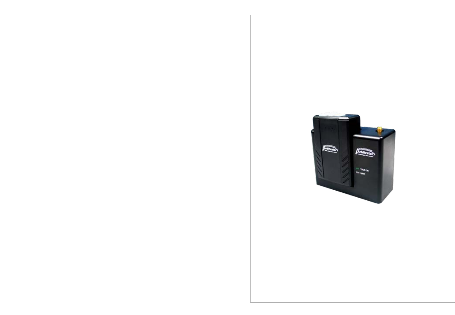
BOX CONTENTS
1. Transmitter (TX)
2. Receiver (RX)
3. Plug-In Microphone (MONO)
4. Mounting Bracket for Receiver with screw
5. Rechargeable Li-Ion Battery
6. Leather Pouch
7. External antenna
8. Desktop charger for transmitter
9. AC Power supply for desktop charger
- Check the battery status
Unit does not
respond
- Check the power switch on the bottom of
the unit
- Check the connection and cables
TIP2 Preserving the Batteries
In order to maintain the optimum capacity of the rechargeable battery pack,
the unit has to be fully discharged (by using) approximately every 6 months.
Then recharge the battery to full capacity again.
9
10. Charger Stand for Desktop Charger
11. Straight Type internal antenna
12. RF Main Cable
13. In-car MIC
14. Instruction Manual
2
Page 3

DESCRIPION – Main Cable
1A In-Line Fuse
DESCRIPION - Receiver
To Receiver
1
Power
(Red)
Power GND
(Black)
Audio Out
(RCA connector)
Trigger REC
(Yellow)
GND
(Black)
Connection with the system
- Power DC12V (Red), Power GN D (Bla ck): Po wer Ca bl e s t o en g in e
battery.
- Audio Out (RCA Connector): Connects to “AUDIO IN 1
” p ort in the
back of recorder.
- Trigger REC (Yellow): Connect to GPIO1 brown cable.
- GND (Black): Connect to GPIO black cable.
<Front>
5
<Rear>
1 Antenna Connection
2 Talk On (Green LED)
BATT (Battery Status)
3
Charging Pin / Matching ID
4
* # 2 Talk On LED
When TX triggers the recording of the
system, green LED lights on.
2
3
4
6
7
<Bottom>
5 Serial Number Label
6 Main Cable Connection
7 FCC Label
* # 3 Charging Status
Red LED – In charging
Green LED – Fully Charged
7
4
Page 4

OPERATION
- Install the bracket by using the screws
- Slide RX Set onto the Bracket
- Connect the main cable to RX Set
- Connect the antenna (Internal Antenna or External Antenna
to the RX Set.
OPERATION
* Place external antenna on the windshield at the point (Horizontal
or Vertical) as following picture.
< External Antenna Installation >
- Put the battery pack into TX Set
- Switch the power ON
(located on the bottom of TX unit)
1. Charging mode
- While TX is placed in RX (No LED on), charging the battery
2. TALK mode
- While TX is displaced from Rx, TX TALK button will be standard
mode on automatically in 3 seconds
(LED blinking 2 times and then LED off ).
RX “TALK ON” LED will not be on since it’s not recording.
- While press TALK button on TX to trigger recording, TALK button
turns blue LED on. RX “TALK ON” LED will light up and
steady green
* When TX is out of range, Blue talk button will be changed by mode,
“ LED off / Beep > LED off / Vibration > LED off / Beep+Vibration
> LED off / None “
* While TX comes back in range, blue LED will be back on (steady).
* When the battery in low, blue talk button will be changed by mode
“LED blink fast > LED off > LED blink fast > LED off “
3. Warning MODE: MODE Selection button.
When a user pushes this button, the mode is changing in order.
“ Beep Tone > Vibration > Beep and Vibration > None “
- Prior to use, charge the unit by placing TX set in the
RX set at least for 3 hours
- Place TX on RX to sync the code
5 6
4. “M” : Mute Button
When this button is pushed, audio data is not output during “Talk
On” mode. Talk button will be changed with next mode order.
“ LED blink slow > LED off > LED blink slow > LED off “
Page 5

DESCRIPTION - Transmitter
1
DESCRIPTION - HOME CHARGER
3
2
Battery LED
4
1 Beep Tone
2 Built-in MIC
Microphone Jack
3
FCC Label
4
Serial Number Label
5
5
Power Adapter Connector
* Battery LED : In Charging – Red LED
Fully Charged – Green LED (4V ~ 4.2V)
(Note) Place TX on the charger at least 4.5se c for th e initializin g.
<Rear><Front>
Installation for Charger stand
6
7
<Top><Bottom>
6 TX Power On/Off
7 Battery Cover
8 Mute Button
9Talk Button
10 Mode Selection Button
8
9
10
Charger Stand
TIP1 How to detach TX from RX and Home Charger
To prevent units from being broken by the improper use,
detach TX unit from RX unit as the drawing described
on the right picture.
3
8
Page 6

CAUTION
SPECIFICATION
- Use only provided antenna with RX Set
- Do not immerse in water or keep in humid areas
- Do not place near TV, speakers, or other electronic devices
- Before installation, check power supply and voltage to avoid
hazards
- Do not apply force or shock to the unit
- Do not disassemble the unit
- Placement of items on the duty belt can restrict ready access to
important equipment. The location of the wireless transmitter or any
other device provided with this system that is carried on the
officer's person should be chosen with care and consideration.
After a location is selected, the officer should test access to and
practice drawing primary items such as service firearms and
secondary defense devices such as Aerosol Subject Restraint,
Batons, Electronic Disruption Devices, etc. Proper operation of
handheld radios and other signaling devices should also be tested as
should access to handcuffs and other restraining devices
- Do not ware body-worn cords in such a way that can cause
strangulation (i.e. loop around the neck or any other body part)
Power DC 12V for RX
Frequency (MHz) 902 ~ 927MHz Band Width
Number of Channel 20Channels
Channel Space 1.2MHz
Speech Coder 32Kbps ADPCM with parity
Type of Modulation DBPSK SS MODULATION/DEMODULATION
Processing Gain 11dB
Data Rate 80Kbps Time Division Duplex
Frame Rate 1.92M Samples/s (2 Samples/Chip)
Receiver Sensitivity -102dBm, -82dBm
Battery Talking Time: 12Hours
Charging Time: 3Hours
Battery Capacity Lithium-ion 3.7V DC/ 2000mA
TX power levels 100mW, 10mW, 1mW
Temperature Range
Dimensions (WxDxH) TX: 54mm x 30.5mm x 83.6mm
1
-20°C ~ 60°C
RX: 104mm x38mm x 81.5mm
10
 Loading...