

Page 1
Panasonic Solutions Company
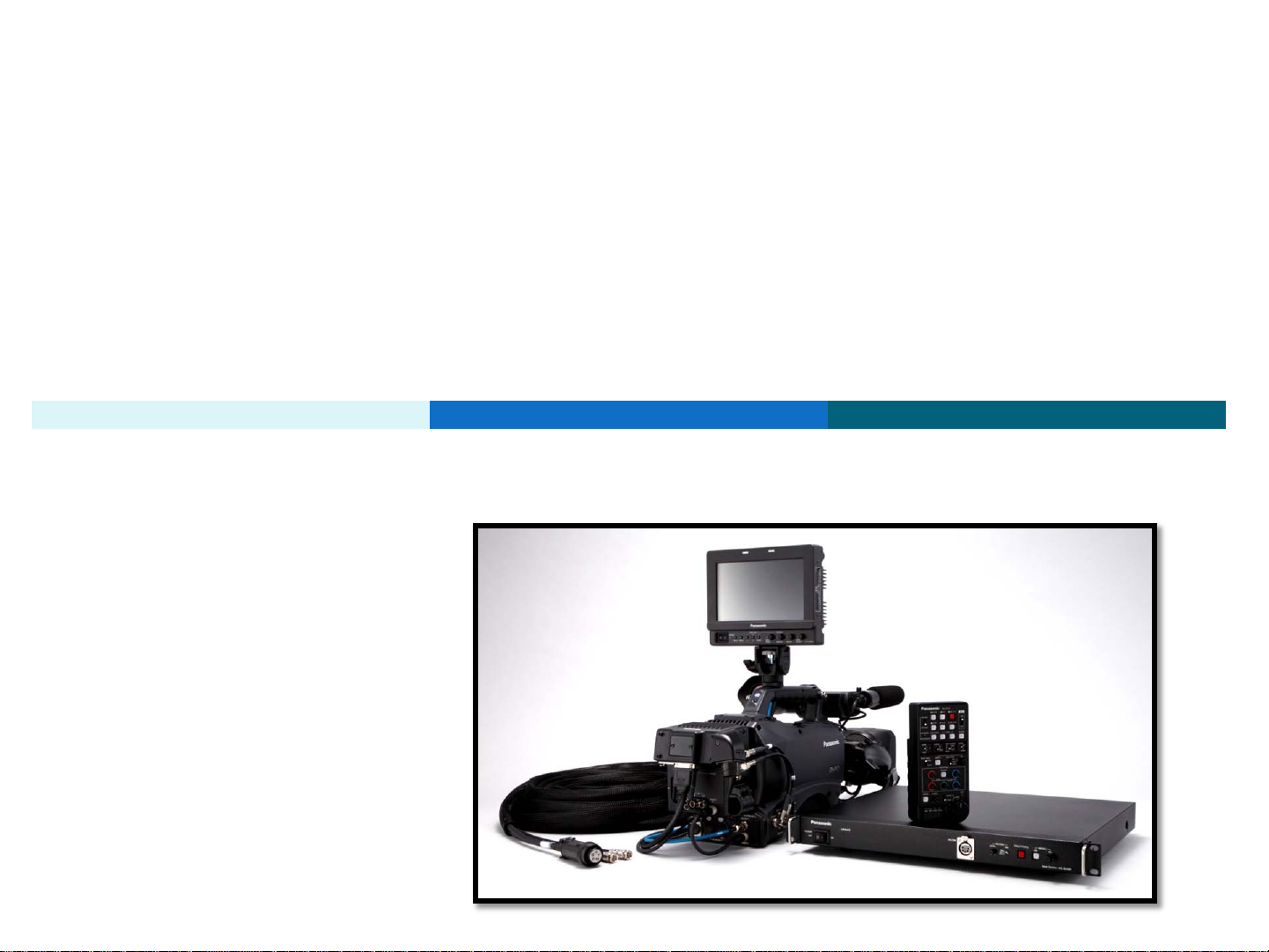
Studio System 300
Basic Installation Guide
1
Page 2

Panasonic Solutions Company
Table Of Contents
DESCRIPTION Page DESCRIPTION Page
Important Power OFF 3 Block Diagram 25
Introduction 4 GPI Menu 26
Base Station AG-BS300 5 Battery Menu HPX370 and HPX500 27
Camera Adaptor AG-CA300 6 Battery Menu HDX900 though HPX3700 28
Battery Mount 7 GenLock Menu Settings 29
ROP AG-EC4 8 SDI Switch and Menu settings 30
ROP AJ-RC10 9 RTS Intercom Connections 31
View Finder Interface AG-YA500 10 Clear-Com Intercom Support 32
Studio Cable 300 11-12 HPX500 DA Setup 33-34
ROP Cable 10M 13 Fiber Option 35-36
ROP Cable 9” 14 Trouble Shooting 37-38
GenLock and SDI 15 Accessory Parts List 39
VF GPI/Return Cable 16 Cable Technical Reference 40-44
Lens Return Cable 17-18 AV-HS400A Tally Connection 45
Lens Return with Tally Option 19 AV-HS450 Tally Connection 46
Tally Trigger Cable 20 Prompter Connection 47
Power Tap Mentor Power Cable 21 Replacement Parts 48
Power T ap Multi Adaptor 22 Support Hot Line 49
VF Cable 23 Notes 50
AJA Pow er Cable 24 .
2
Page 3

Panasonic Solutions Company
IMPORTANT
POWER OFF
Please make sure the power is turned OFF
on all equipment before making any connec t ions!
3
Page 4

Panasonic Solutions Company
Section 1 - Studio System 300
Introduction
The Studio System 300 will work with the following cameras:
AG-HPX300, AGHPX370, AGHPX500, AJ-HDX900, AJ-HPX2000,
AJ-HPX2700, AJ-HPX3000, AJ-HPX3100 and AJ-HPX3700.
Before installation of the Studio System 300, Lets review
all of the components and its function.
4
Page 5
Panasonic Solutions Company
Section 1 - Studio System 300
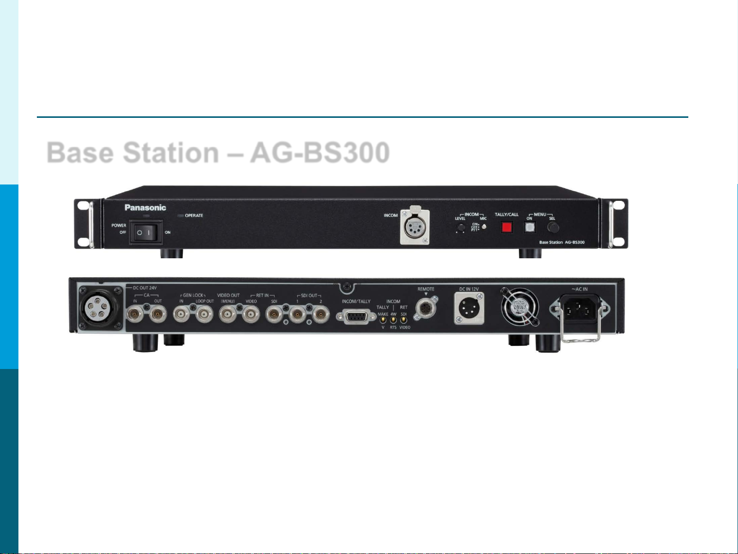
Base Station – AG-BS300
Front
Back
The Base Station AG-BS 300 is the heart of the system.
It provides the following: Power to the Camera*, Tally, Intercom, GenLock,
Return Video (SDI or Video or Both) and ROP Control.
*Does not provide power under the following 3 conditions:
1. The Base Station is powered using 12 Volts DC.
2. A Fiber Option is used in place of t he studio cable.
3. Using 2 RG6 Type BNC Cables Only (no power cable).
5
Page 6
Panasonic Solutions Company
Section 1- Studio System 300
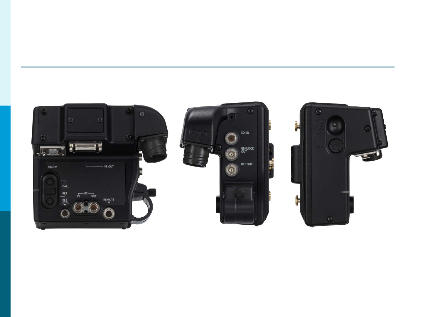
Camera Adaptor – AG-CA300
Back
The Camera Adaptor AG-CA300 attaches to the Anton Bauer Gold M ount
on the back of the Camera. I t does the following:
Right Left
Connects to the GenLock, S D I Out, ROP, Provides Intercom, Return
Video (SDI or Video or Both), GPI, Tally, Tally Out Trigger
and Power. It only needs 3 connections to connect with the Base Station
(1 Power and 2 SDI).
6
Page 7
Panasonic Solutions Company
Section 1- Studio System 300
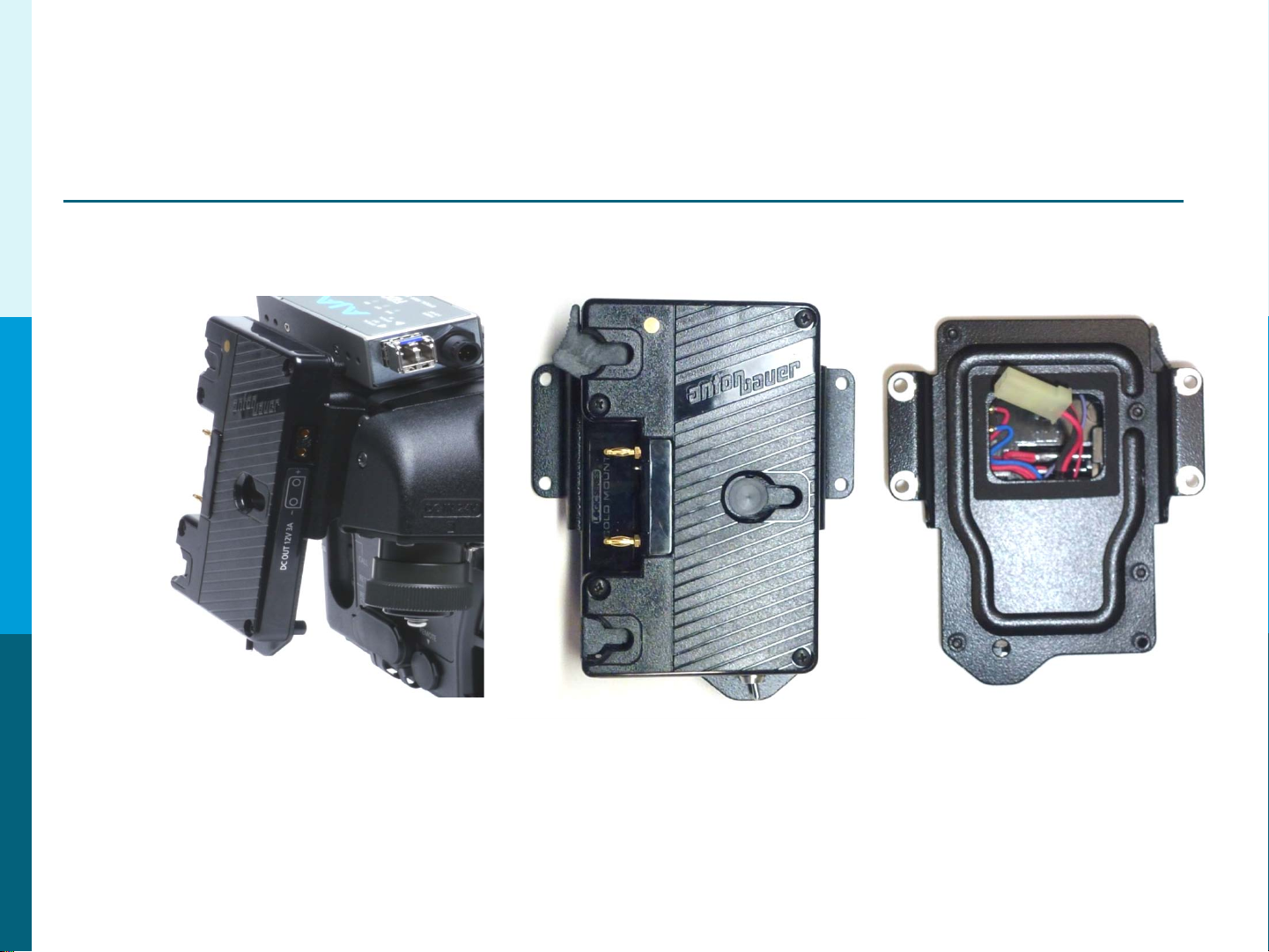
Battery Mount Option – Anton Bauer Gold Mount
If using a fiber option to r un a c abl e length more than 100 M,
power must be provided loc al ly at the camera head. The supplied
Anton Bauer Gold Battery Mount must be used. Do Not Try to power
the camera using the 4 Pin XLR 12V input. The system can only be
powered though the batt er y mount.
7
Page 8
Panasonic Solutions Company
Section 1- Studio System 300
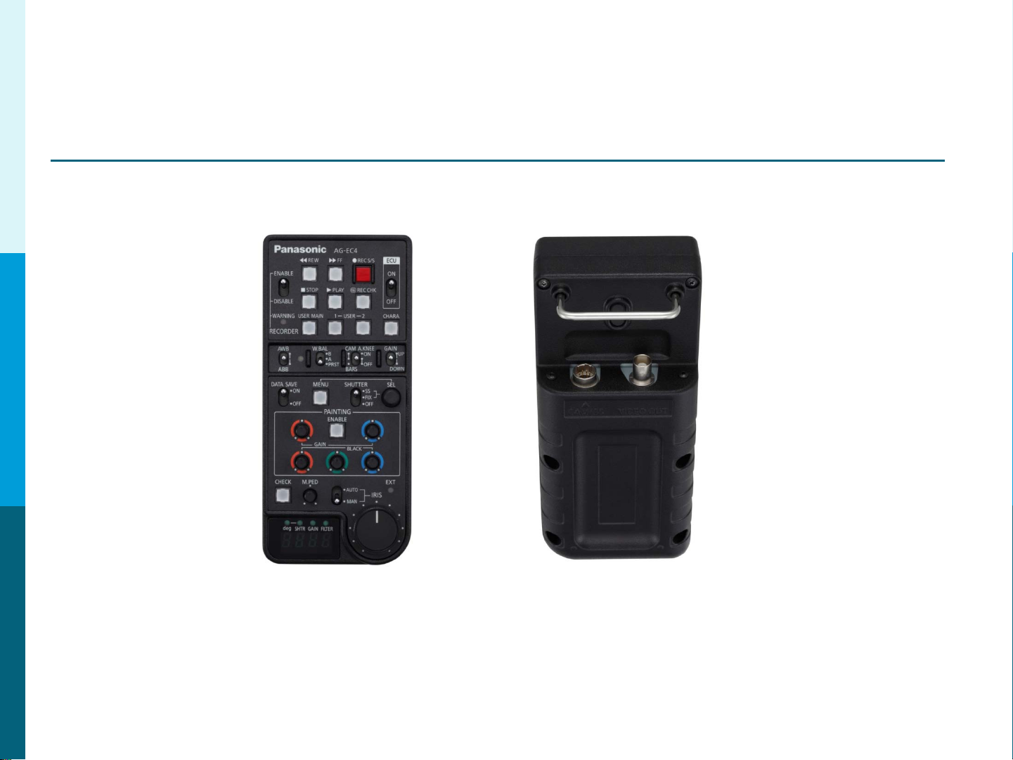
Remote Operation Panel (ROP) AG-EC4
Front Back
The Remote Operation Panel (ROP) AG-EC4 is a simple control
panel that works with all system supported cameras.
This includes the following:HPX300, HPX370, HPX500, HDX900,
HPX2000, HPX2700, HPX3000, HPX3100 and HPX3700.
8
Page 9
Panasonic Solutions Company
Section 1- Studio System 300
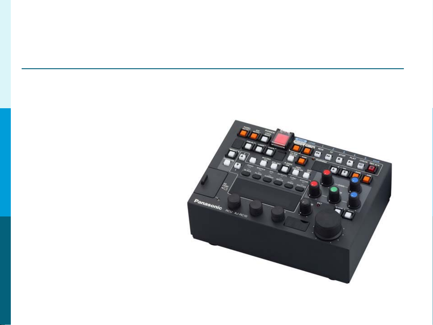
Optional Remote Operation Panel AJ-RC10
Not Recommended for AG-HPX300, AG-HPX370 or A G-HPX500
The AJ-RC10 is a full featured
Remote Operation Panel.
It is recommended for t he
Cameras that offer more
control options. Example:
Knee and Slope Controls,
Master Gama, Etc.
It is not recommended for
the HPX300, HPX370 or HPX500
as they are better suited to use the AG-EC4.
Cameras that can take advant age of the AJ-RC10:
HDX900, HPX2000, HPX2700, HPX3000, HPX3100 and HPX3700
9
Page 10
Panasonic Solutions Company
Section 1- Studio System 300
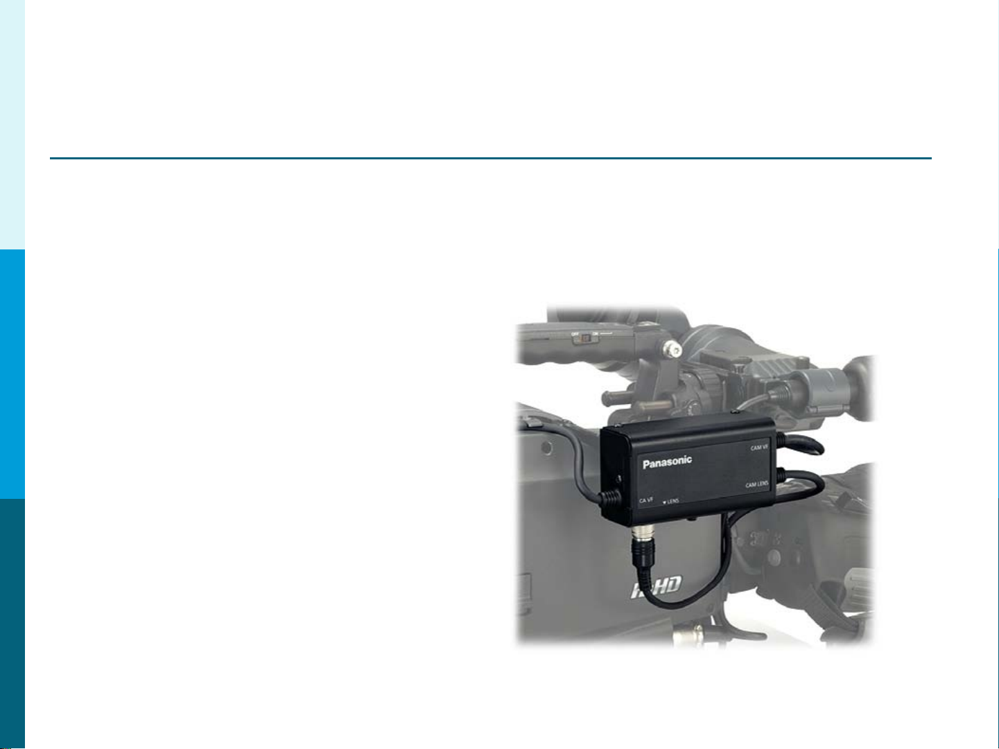
View Finder Interface Box– AG-YA500
Not Available for AG-HPX300 or AG-HPX370
The AG-YA500 VF Interface Box
allows Return Video and Tally
to be sent to the View Finder.
This option is usually used when
the camera is in a hand held
configuration and or no on boar d
Monitor is present.
10
Page 11
Panasonic Solutions Company
Section 2 – Cable Identification
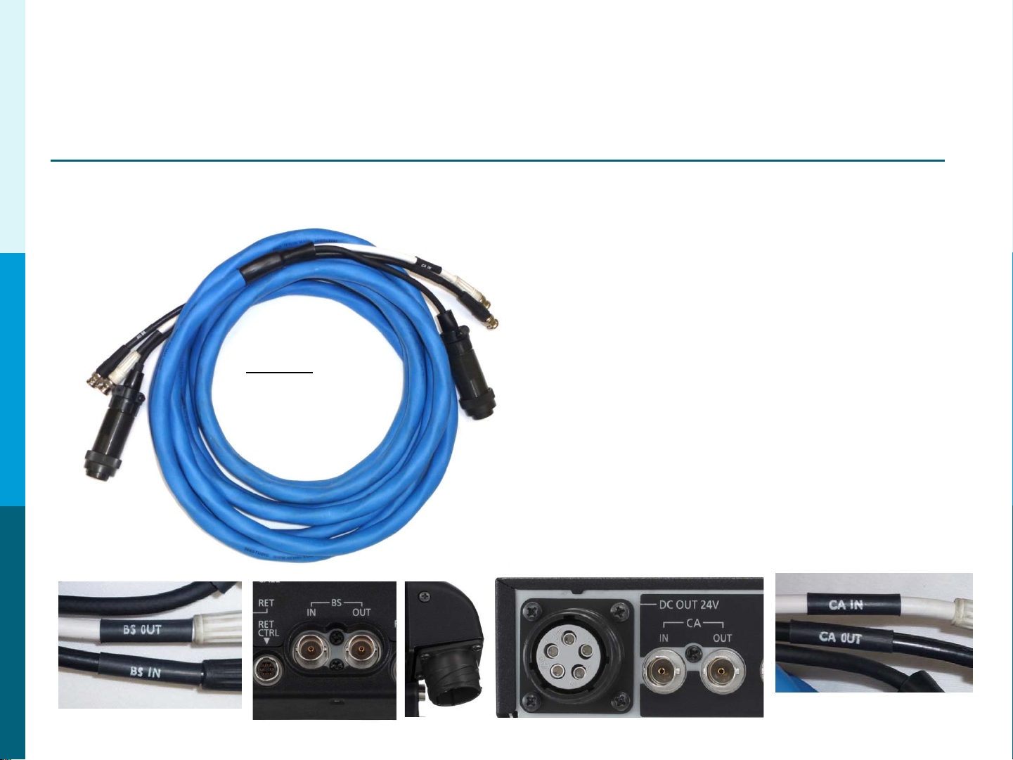
Studio 300 Cable
The Studio 300 Cable connects the
Camera Adaptor AG-CA300 to the
Base Station AG-BS300.
It is available in lengths of
25, 50 or 100 Meters.
Cable Labels
Part #’s
Studio300/100
Studio300/50
Studio300/25
It contains a DC Power Cable and 2
SDI cables.
The Maximum Distance that
can be used is 100 Meters.
For longer lengths, a F iber Option is
Recommended
(Explained later in t hi s gui de) .
Cable Labels
11
Page 12
Panasonic Solutions Company
Section 2 – Cable Identification
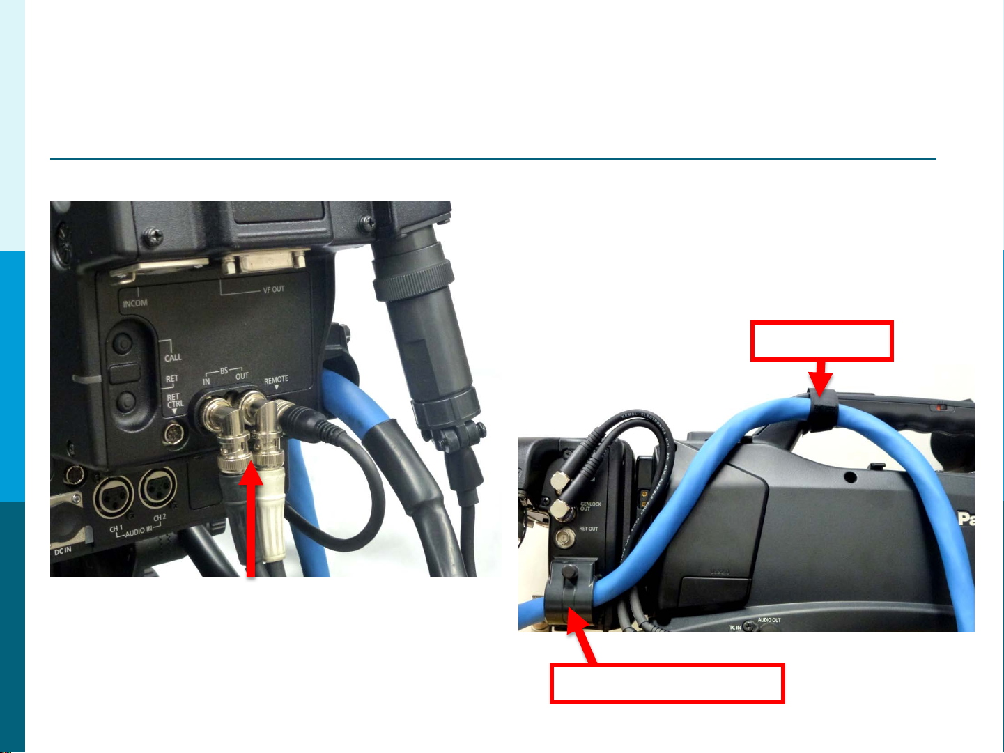
Studio300 Cable
To increase cable reliability,
please loop the studio cable
through the strain relieve and
secure with the supplied cable
strap as shown.
Cable Strap
In order to make the BNC Connection
easier to attach to the AG-CA300, use the
2 right angle BNC adaptors supplied with
the Studio Cable.
Strain Relieve Clamp
12
Page 13
Panasonic Solutions Company
Section 2 – Cable Identification
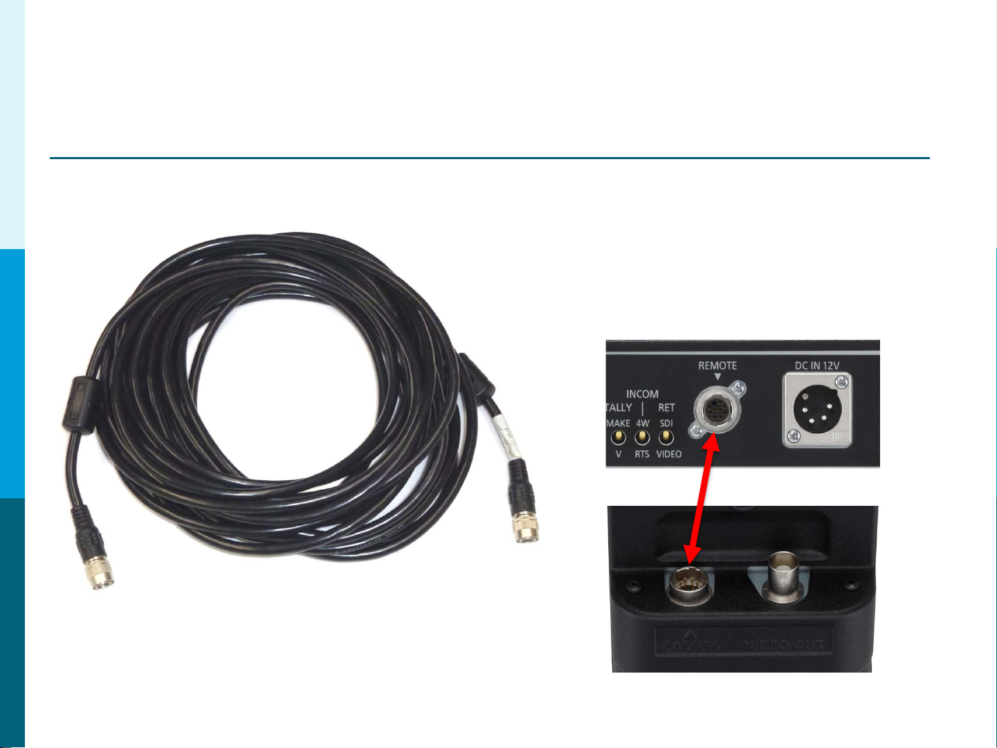
10M ROP Cable
The 10 Meter ROP Cable Connects
the AG-EC4 (or AJ-RC10) to the B ase
Station AG-BS300 Remote In.
It is also available in 50 Meter lengths.
AG-BS300
AG-EC4
13
Page 14
Panasonic Solutions Company
Section 2 – Cable Identification
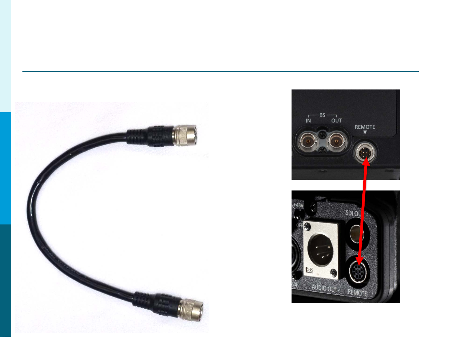
9” ROP Cable
The 9” ROP Cable Connects the
Camera Adaptor AG-CA300 Remot e
to the Camera Remote.
This Cable Must Be connected for
the system to work.
The connection is very delicate so
please handle with extreme care and
make sure all power is off.
14
Page 15
Panasonic Solutions Company
Section 2 – Cable Identification
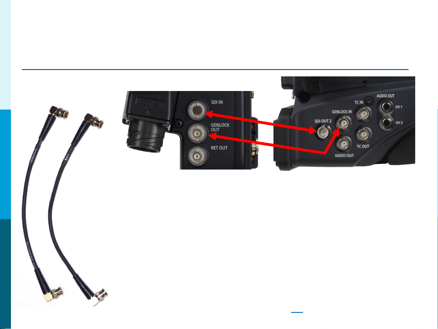
GENLOCK and SDI
These 2 short BNC cables connect:
1. AG-CA300 Camera Adaptor GenLock Out to the Camera G enLoc k In.
2. AG-CA300 SDI in to the C am era SDI Out.
Note: When connecting to t he H P X300, HPX370 or HPX500,
these cameras will automatically GenLock when the
GenLock Cable is connected. However, the HDX900,
HPX2000, HPX2700, HPX3000, HPX3100 and HPX3700
must be manually set to Exter nal GenLock in the
System Menu. Failure to turn this menu item on will
result in NO ROP control. See Page 29
for Menu Settings.
15
Page 16

Panasonic Solutions Company
Section 2 – Cable Identification
GPI/Return VF Cable
Component
SDI
From
Camera
On Board
Monitor
GPI
AG-CA300
16
Page 17

Panasonic Solutions Company
Section 2 – Cable Identification
Optional – Lens Return Cable (Part # 300LensReturn)
LENS
LENS
PORT
RET
CTRL
The 300LensReturn Cable
allows return video s witching via the Lens
Ret Switch or Rear Lens Controls. See the
next page for connection details.
17
Page 18

Panasonic Solutions Company
Section 2 – Cable Identification
Optional – Lens Return Cable (Part # 300LensReturn)
Remove Lens Cable
Insert Lens Y Cable
Connect a cable which is
remaining to CA300 RET
18
CTRL terminal.
Page 19

Panasonic Solutions Company
Section 2 – Cable Identification
Optional – Lens Return w/ Tally (Part # 300LensYTally)
LENS
The 300LensYTally is similar
to the 300LensReturn cable
with the following difference:
It allows the Tally Out signal
from the AG-CA300.
LENS
PORT
TALLY
OUT
RET
CTRL
19
Page 20

Panasonic Solutions Company
Section 2 – Cable Identification
Optional –Tally Trigger Cable ( Part # 300TallyTrigger)
Note: For use only with t he AG-HPX300, AG-HPX370 and AJ-HPX3100.
Allows Tally Lights on the Camera View Finder and Camer a Body to illuminate.
Also, the internal VF Tally will illuminate. Connect the 6 Pin RET CTRL on the
AG-CA300 to the 4 Pin DC Out on the Camera.
20
Page 21

Panasonic Solutions Company
Section 2 – Cable Identification
Optional – Power Tap 28” (Part # PowerTap28)
This cable Provides 12 Volt DC Power
for the On Board Monitor.
Connect the P-Tap Plug to the
P-Tap Jack on the Camera. Connect
the 4 Pin XLR to the Monitor DC In.
Note: Power Tap-28 = 28”
Power Tap-20 =20”
IMPORTANT NOTE: Do Not Power the BT-LH910 Monitor from the
4 Pin Lemo 12V 1.5A DC O u t o n the c am era body. Do to the
current requirement on the BT-LH910, only use the P-Tap
or external source to power the monitor.
21
Page 22

Panasonic Solutions Company
Section 2 – Cable Identification
Optional – Multi P-Tap Adapt or (Part # PowerTap-Multi)
Some Configurations require more than
one P-Tap. The Multi Tap will give a
total of 4 P-Tap 12 Volt DC outputs.
An Example would be using the AJA
Fido TR Fiber Option. The Monitor and
AJA Device will both need DC Power.
22
Page 23

Panasonic Solutions Company
Section 2 – Cable Identification
Optional – BT-CS910G VF Cable
Not for use on AG-HPX300, AG-HPX370 or AG-HPX500
The BT-CS910G Cable allows the on
board monitor (BT-LH910 or BT-LH80) to
use the camera VF out connector . This
will provide all VF on screen status
information and markings . It will also free
up a camera SDI out connection which
can be used for other uses.
23
Page 24

Panasonic Solutions Company
Section 2 – Cable Identification
Optional – AJA P-Tap Power Cable
This cable Provides 12 Volt DC Power
for Optional AJA Fido TR Fiber Device
or for an AJA DA.
Example: AG-HPX500 has only 1 SDI out. This
camera will need the AJA DA to provide additional
SDI outputs. One for the AG-CA300 and the
other to feed the On Board Monitor . If this
example configuration is used, it will also require
the Multi Tap to provide the additional accessories
power needs. In this case, the On Board Monitor
and the AJA DA. Note: The BT-CS910G cable is
not recommended for the AG-HPX500.
If Using the AJA DA, Please be sure to check the
voltage input range. Some AJA Products only run
on 5 Volts DC.
24
Page 25

Panasonic Solutions Company
Section 3 – System Overview
2525
Page 26

Panasonic Solutions Company
Section 4 – MENU SETUP
On Board Monitor GPI Assignment
1. Press Menu button on Panasonic Monitor
2. Select GPI
3. GPI Control = Enable
4. GPI 1 = R-Tally
5. GPI 2 = G-Tally
6. GPI 3 = INPUT SEL. YPBPR
7. GPI 4 = INPUT SEL. SDI1 (or VF if using BT-CS910G cable)
8. Exit Menu
26
Page 27

Panasonic Solutions Company
Section 4 – MENU SETUP
Camera Battery Menu Setup
AG-HPX300, AG-HPX370 and AG-HPX500
1. Press Menu button.
2. Select Battery Setup.
3. Battery Select = Type B
4. Scroll Down to Type B and select values.
Full = 13.0V
Near = 12.5V
End = 12.0V
5. Exit Menu.
27
Page 28

Panasonic Solutions Company
Section 4 – MENU SETUP
Camera Battery Menu Setup
AJ-HDX900, AJ-HPX2000, AJ-HPX2700, A J-HPX3000, AJ-HPX3100, AJ-HPX3700
1. Press and hold the menu butt on for 2 seconds to enter menu.
2. Select Main Operation.
3. Select Battery/P2 Card
4. Battery Select = Type B
5. Exit Back to Main Operation Menu
6. Select Battery Setti ngs or Battery Settings 2 (depending on camera)
7. Scroll Down to Type B and select values.
Full = 13.0V
Near End = 12.5V
End = 12.0V
8. Exit Menu
28
Page 29

Panasonic Solutions Company
Section 5 – MENU SETUP
Genlock Menu Setup
AJ-HDX900, AJ-HPX2000, AJ-HPX2700, A J-HPX3000, AJ-HPX3100, AJ-HPX3700
1. Press and hold the menu butt on for 2 seconds to enter menu.
2. Select System Settings.
3. Select Genlock
4. Genlock = GL IN or EXT (depending on camera)
5. Exit Menu
NOTE: AG-HPX300, AG-HPX370 and AG-HP X500 will auto G enlock when a
signal is connected and do not require setting Genlock to EXT.
29
Page 30

Panasonic Solutions Company
Section 5 – MENU SETUP
SDI Video Out Setup
AJ-HDX900, AJ-HPX2000, AJ-HPX3000
Set the Video Out Switch to HS-SDI or SD-SDI respectively.
The switch is located under the camera side door.
AJ-HPX2700, AJ-HDX3700
Set the HD-SDI A-B Switch to MEM or CAM.
The switch is located under the camera side door.
AG-HPX300, AG-HPX370 and AG-HPX500
1. Press Menu button.
2. Select OUTPUT SEL.
3. Select SDI = AUTO
4. Exit Menu
AJ-HDX900
AJ-HPX2000
AJ-HDX3000
AJ-HPX2700
AJ-HDX3700
30
Page 31

Panasonic Solutions Company
Section 5 – Intercom Connection
RTS TW Intercom Connection to AG-BS300
1. Set INCOM switch on BS-300 to RTS (2 wire, AKA TW).
AG-BS300
2. Tur n down all volume levels before powering on.
3. Connect Pin 8 on AG-BS300 to Common (pin 1) on RTS TW.
4. Connect Pin 7 on AG-BS300 to Channel 1 (pin 2) OR use
Channel 2 (pin 3) on RTS TW.
Example Shown with Channel 2. If Channel 1, the red line would connect to pin 2.
Channel 2 Example
1 2
3 Pin XLR
RTS TW
3
IMPORTANT NOTE: If not connecting to an RTS or Clear-Com System, 200ohm Termination
must be installed between Pins 7 and 8 on the AG-BS300 INCOM/TALLY Connection.
AG-BS300
31
Page 32

Panasonic Solutions Company
Section 5 – Intercom Connection
Clear-Com Intercom Connection to AG-BS300
A Clear-Com IF4W-4 Interface is required to connect to the AG-BS300.
AG-BS300
1. Set INCOM switch on AG-BS300 to 4W
2. Turn down all volume levels before powering on.
3. Connect Pin 1 on AG-BS300 to Pin 4 on IF4W-4
4. Connect Pin 3 on AG-BS300 to Pin 1 on IF4W-4
5. Connect Pin 6 on AG-BS300 to Pin 5 on IF4W-4
6. Connect Pin 7 on AG-BS300 to Pin 2 on IF4W-4
RECV
IF4W-4
Terminal
Block
Rear Panel
IMPORTANT NOTE: If not connecting to an RTS or Clear-Com System, 200ohm Termination
must be installed between Pins 7 and 8 on the AG-BS300 INCOM/TALLY Connection.
RECV
INT
GRD
XMIT
XMIT
1
2
3
4
5
AG-BS300
32
Page 33

Panasonic Solutions Company
Section 6 – AG-HPX500 DA
Using the AG-HPX500 with an on Board Monitor
The AG-HPX500 uses a Standard Definition B&W View Finder.
This image will appear very soft if the on board monitor was connected
to the camera VF Out. For this reason, we DO NOT recommend the BT-C S910G VF cable.
An AJA Model HD10DA is recommended as a better solution. Because the AJA HD10DA
has an Input voltage rage from 5 to 18 Volts DC, it makes it a very suitable choice.
This will provide a much better image on the on board monitor (and in Color).
SDI
SDI OUT
SDI
MultiTap
PowerTap28
BT-Mount
Parts List
AJA HD1 0DA
AJA P-Tap Power Cable
Power Tap 28 Cable
Multi-Tap
BT-LH910
BT-Mount or Yoke Mount
33
Page 34

Panasonic Solutions Company
Section 6 – AG-HPX500 DA
SDI
SDI
BT-Mount
PowerTap28
MultiTap
SDI OUT
34
Page 35

Panasonic Solutions Company
Section 7 – Fiber Options
AJA FIDO TR
The AJA Fido TR will allow the
Studio System 300 to work with a
distance of up to 6.2 miles us ing
Low Cost Single Mode Duplex Fiber
Cable with LC Termination.
With this option, the camer a must be
powered locally using the supplied
Anton Bauer Gold Mount.
AJA Parts List
2 x Fido TR
1 x DWP (ac power supply)
1 x AB DC power cable
Single Mo de Du plex Tactical Fiber Ca ble with
LC Termination at each end.
Lengths up to 6.2 miles.
Local Power Supply for Camera.
Please visit AJA .com for more information
and resellers.
35
Page 36

Panasonic Solutions Company
Section 7 – Fiber Options
AJA FIDO TR
Single Mode Duplex Fiber Up To 6.2 Miles
AC Adaptor
AG-BS300
Base Station
Mounts to AG-CA-300
Bracket Not Shown
12 VDC IN
VIA Gold Mount
(adaptor not shown)
12VDC Cable
SDI I/O
To Camera D-Tap
AC IN
ROP, GEN LOCK and SDI Connections
SDI I/O
AG-CA300
Mounts to Camera Back
AG-EC4
The Studio System Works With the Following Cameras:
AG-HPX300, AG-HPX370, AG-HPX500, AJ-HDX900, AJ-HPX2000, AJ-HPX2700, AJ-HPX3000, AJ-HPX3100, AJ-HPX3700
36
Page 37

Panasonic Solutions Company
Section 8 – Trouble Shooting
Common Issues
Remote Control (ROP)
Problem:
No ROP Control and ROP shows Initializing (RC10) or dashes (EC4)?
Solutions:
A: Confirm that the 9” ROP is attached from the AG-CA300 remote connector to the other end to
camera remote connector (see page 14
B: Confirm that the GenLock Cable is connected between the AG-CA300 GenLock Out and
Camera Genlock In (see page 12
C: Confirm that the GenLock is set to GL IN or EXT in the Genlock Section of the System Menu.
This is not necessary for the HPX370 and HPX500 as they will auto set to EXT Genlock when a
signal is applied (see page 29
).
)
)
System doesn’t work when camera is using local power.
Problem:
The System will not work when I power the camera locally using the camera 4 pin XLR?
Solution:
When powering the camera locally (not though the Studio Cable), power must be connected
though the AG-CA300 via the supplied Gold Mount battery adaptor. You cannot power the
camera using the 4 Pin XLR connector on camera body.
37
Page 38

Panasonic Solutions Company
Section 8 – Trouble Shooting
Common Issues
Base Station lights Flash and nothing works.
Problem:
The Base Station light is flashing and nothing works?
Solutions:
A: Check that all connections are correct and no cables are swapped.
B: If using an AJ-HDX900, AJ-HPX2000 or AJ-HPX3000, check to make sure the Video Out
Switch is set to H D-SD I or SD-SDI respectively. If using an
AJ-HPX2700 or AJ-HPX3700, set SDI A-B to MEM or CAM.
If using an AG-HPX300, AG-HPX370 or AG-HPX500,
check the menu settings> OUTPUT SEL> SDI> AU T O
SDI
Side
Switch
Return Button makes the lens zoom in.
Problem:
When pressing the Return button on the lens, the lens zooms in?
Solutions:
Check the lens internal dip switch settings and turn of f Auto Cruise Zoom.
On Board Monitor is Low Resolution.
Problem:
The Camera is shooting in HD, but the on board monitor is in SD?
Solutions:
Check the Monitor GPI menu settings. GPI # 4 should be set to SDI or VF (see page 26
AJ-HDX900
AJ-HPX2000/3000
AJ-HPX2700/3700
)
38
Page 39

Panasonic Solutions Company
Section 9 – Accessory List
PART NUMBER DESCRIPTION Page
Studio Cable 300/100 100M Studio Cable 11
Studio Cable 300/50 50M Studio Cable 11
Studio Cable 300/25 25M Studio Cable 11
300LensReturn Lens Return Control Cable 17
300LensYTally Lens Return Control Cable w/ Tally Out option 19
300TallyTrigger Tally Trigger Cable (for HPX300/370/3100 Only) 20
PowerTap-28 28” P-Tap to 4 Pin XLR 12V Power Cable for Monitor 21
PowerTap-Multi P-Tap Splitter – Provides 4 P-taps from 1 P-Tap 22
BT-CS910G VF Cable (not for HPX300 HPX370 HPX500) 23
AJA Pow erTap AJA P-Tap 12V Power Cable for DA or Fido TR 24
BT-LH910G 9” On Board Monitor
BT-Mount Simple Monitor Mount
Yoke910 Yoke Mount for Precision Monitor Mounting
MOH-LH910L Long Sun Hood for BT-LH910
MOH-LH910 Short Sun Hood for BT-LH910
EC4-Rack EC4 Rack Mount (mounts 4 EC4 units)
EC4-Blank Additional EC4 Blank Panels for Rack Mount
RC10-Rack RC10 Rack Mount (mounts 2 RC10 Units)
BS300-Rack Rack Mount for AG-BS300 Base Station
Please visit our website for more information:
http://www.panasonic.com/business/provideo/home.asp
39
Page 40

Panasonic Solutions Company
Section 10 – Reference
Studio System Power Connectors
40
Page 41

Panasonic Solutions Company
Section 10 – Reference
Studio System Power Cable
41
Page 42

Panasonic Solutions Company
Section 10 – Reference
300LensReturn Cable
42
Page 43

Panasonic Solutions Company
Section 10 – Reference
300LensYTally Cable
43
Page 44

Panasonic Solutions Company
Section 10 – Reference
300TallyTrigger Cable
44
Page 45

Panasonic Solutions Company
Section 10 – Reference
AV-HS400A Tally Connection
45
Page 46

Panasonic Solutions Company
Section 10 – Reference
AV-HS450 Tally Connection
46
Page 47

Panasonic Solutions Company
Section 10 – Reference
Prompter
47
Page 48

Panasonic Solutions Company
Section 10 – Reference
Common Replacement Parts
9” Remote Cable
# VEE1G47
10M Remote Cable
# K1EY10YY0001
Panasonic Parts Center 800-334-4881
VF Cable
# VEE1G49
2 short BNC Cables for AG-CA300
To Camera SDI and GenLock
# RG59-1FT/BNCRA-BNCRA
Anton Bracket
# VFC4493
Cable Strap
48
# VFC4490
Page 49

Panasonic Solutions Company
Section 11 - Conclusion
Please refer to the individual operating man uals
provided in you r package for deta i l ed
instructions on setting up and operating your
equipment.
For additional Support, please call us toll free at:
855-PSC-TECH (855-772-8324)
49
Page 50

Panasonic Solutions Company
Section 12 - NOTES
________________________________________________
________________________________________________
________________________________________________
________________________________________________
________________________________________________
________________________________________________
________________________________________________
________________________________________________
________________________________________________
________________________________________________
________________________________________________
________________________________________________
________________________________________________
________________________________________________
________________________________________________
50
 Loading...