

Panasonic STAV-3770 User Manual
Cat. No.
Audio/Video
Receiver
STAV-3770
31-3042
STANDBY
POWER
DSP
SPEAKER
PHONES
STAV-3770 AUDIO/VIDEO RECEIVER
MEMORY FM MONO CLASS
STATION
TUNING
EQUAL POWER OUTPUT
SELECT
4X100WATT
DOLBY SURROUND
PRO LOGIC
DSP
DOLBY
MODE
DSP
DIGITAL
SIGNAL
PROCESSOR
OSR
TAPE 1
VCR
TAPE 2
PHONOFM/AMCDDVD/LD
MONITOR
LOUDNESS
VIRTUAL
DOLBY
PRO LOGIC
SELECT
TONE DOWN UP
BALANCE LEFT RIGHT
MIN
VOLUME
MAX
Owner’s Manual
Please read before using this equipment.

Introducing the Optimus STAV-3770
Your Optimus STAV-3770 Audio/Video Receiver is the perfect control center for
your audio/video system. It combines 100 watts-per-channel of clean power
with modern styling. And, it provides connections for one tape deck, one audio/
video source, one more tape deck or audio/video playback source, a turntable,
a CD player, and a video monitor.
Digital-Synthesized Tuner
30 Memory Locations
Automatic Tu ning
Tape Monitoring
Built-In Protection Circuits
Remote Control
Y our receiver also has special sound options.
Dolby Pro Logic‘ Surround Sound
delivers movie theater sound for audio/video programs (especially those
encoded with Dolby Surround Sound signals).
wider sound field than ordinary playback.
ronment that simulates a concert hall, jazz club, theater, or a dance hall.
Virtual
provides a three-dimensional sound field using only the front left and
Dolby 3CH Logic
DSP Effects
provides a
creates a listening envi-
Dolby
right speakers.
Additional features include:
Precisely tunes to AM and FM stations.
Let you store and recall the frequencies for up to 30 AM/FM stations.
Searches for the next available AM/FM station.
Lets you listen to the actual recording as you record, if your tape deck has a
tape-monitoring feature.
Automatically turn off the receiver to help avoid power surges or short circuit
damage.
Lets you use a single remote control for the receiver and other compatible com-
ponents connected to the receiver.
The remote control requires two AA batteries (not supplied).
Note:
We recommend you record the receiver’s serial number here. The number is on the receiver’s back panel.
Serial Number:_____________________________________________
Note to the Cable TV System Installer:
This reminder is provided to call the CATV system installer’s attention to Article 820-40 of the National Electrical Code that
provides guidelines for proper grounding and, in particular , specifies that the cable ground shall be connected to the grounding system of the building as close to the point of cable entry as practical.
Dolby, Pro Logic, and the double-D symbol ( ) are trademarks of Dolby Labo ratories Licensing Corporation.
Manufactured under license from Dol by Laboratories Licensing Corporation.
1998 Tandy Corporation.
RadioShack and Optimus are registered trademarks used by Tandy Corporation.
All Rights Reserved.
3
IMPORTANT SAFETY INSTRUCTIONS
s
d
-
r
-
,
e
e
e
g
d
-
-
o
-
.
.
e
f
-
-
r
-
-
-
.
,
y
.
y
-
-
y
f
-
s
l
n
d
,
s
(
)
This receiver is made and tested to meet exacting
safety stand ards. It meets both UL and FCC requirements
WARNING: TO REDUCE THE RISK OF
FIRE OR ELECTRIC SHOCK, DO NOT
EXPOSE THIS APPLIANCE TO RAIN OR
MOISTURE.
CAUTION
CAUTION
RISK OF ELECTRIC SHOCK.
DO NOT OPEN.
: TO REDUCE THE RISK OF
!
ELECTRIC SHOCK, DO NOT REMOVE
COVER OR BACK. NO USER-SERVICEABLE PARTS INSIDE. REFER SERVICING
TO QUALIFIED PERSONNEL.
This symbo l is intended to alert y ou to the
presen ce of uninsulated d angerous voltage
within the system’s enclosure that might be of
sufficient magnitude to constitute a risk of
electric shock. Do not open the system’s
case.
This s ymb ol is in te nd ed t o inf or m y ou th at i mportant operating and maintenance instruc-
!
tions are included in the literature
accompanying this system.
CAUTION
Power Line s —L ocat e an outdo or ante nna aw ay from
power li ne s.
Nonuse Periods —Unplug the receiver’s power cord
when you will not use it for extended periods.
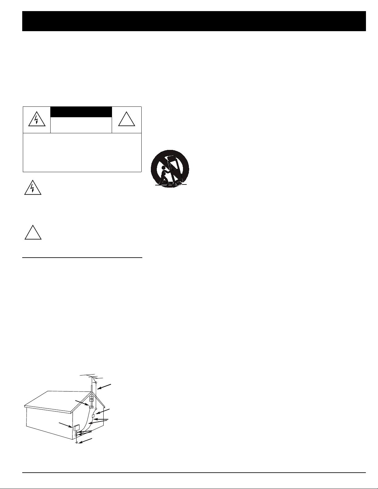
Outdoor Antenn a Groun ding—If an ou tsid e ant enn a
or cable sy stem is connecte d to the receiver, ground
the antenna or cable system so as to provide some
protection against voltage surges and built-up static
charges. Article 810 of the National Electrical Code,
ANSI/NFPA 80, provides information about proper
grounding of the mast and supporting structure,
grounding of the lead-in wire to an antenna discharge
unit, size of grounding conductors, location of antennadischarge unit, connection to grounding electrodes,
and requirements for the grounding electrode. See the
example below.
Antenna
Lead-In
Wire
Ground Clamp
Antenna
Discharge Unit
Electric
Service
Equipment
NEC -- National Electrical Code
(NEC Section 810-20)
Grounding Conductor
(NEC Section 810-21)
Grounding Clamps
Power Service Grounding
Electrode System
NECArticle 250,Part H
Careful attention is devoted to quality standards in the manufacture of your receiver, and safety i
a major factor in its design . However, safety is also your responsib ility.
This section lists important information that will help you properly use and enjoy your receiver an
accessories. Read all the included safety and operating instructions before using your receiver. Fol
low them closely, and retain them for future reference.
Heed Warnings — Follow all warnings on the produc t and in the operating instructions.
Cleaning — Unplu g thi s produc t from the w all outl et bef ore clea ning. U se on ly a dam p cloth fo
cleaning. Do not use liquid or aerosol cleaners.
Attachments — Do not use attachments/accessori es not recommended by the product manufac
turer, as they might create a hazard.
Water and Moisture — Do not use t his prod uct n ear wa ter ( for ex ample , ne ar a bat htu b, wash bowl
kitchen sink, or laundry tub; in a wet basement; or near a swimming pool).
Accessories — Do not place t his product on an unstable cart , stand, tripo d, bracket, or t able. Th
product may fal l, causing serious injury to a child or adult, and serious damage to the product. Us
only with a cart , stand, tripod, bracket, or table recommended by the manufacturer or sold with th
product. Follow the manufacturer's instructions for mounting, and use a recommended mountin
accessory.
Carts — Move the product on a cart carefully. Quick stops, excessive force, an
uneven surfaces may cause the product/cart to overturn.
Ventilation — Slo ts an d openin gs in the c abinet p rov id e ventilation , e ns ur e re li
able operation, and protect from overheating. Do not block or cover these open
ings, and do not place the product on a bed, sofa, rug, or other similar surface. D
not pl ace the product in a built-in bookcase or rack unless it provides proper ven
tilat ion as specified by the manufacturer.
Power Sources — Opera te th is prod uc t usin g onl y the p ower sourc e ind icated on its marki ng la bel
If you are not sure of your home's power type, consult your product dealer or local power company
Polariz ation — Th is pr odu ct is equip ped with a po lariz ed A C line pl ug (a p lu g hav ing on e bla d
wider than the other). This plug will fit in the power outlet only one way. This is a safety feature. I
you cannot insert the plug fully into the outlet, try reversing the plug. If the plug still doesn't fit, con
tact your electrician to replace your obsolete outlet. Do not defeat the safety purpose of the polar
ized plug. If you need an extension, use a polarized cord.
Power-Cord Protection — Route power-supply cords so they are not likely to be walked on o
pinched by items placed on or against them, paying particular attention to cords at plugs, conve
nience receptacles, and the point where they exit from the product.
Lightning — Fo r ad ded prot ec tio n for this product during a li gh tning stor m , o r when it is left unat
tended an d unus ed fo r lo ng per i od s of t im e, un plug it fro m t he wall ou t le t and di sco nn ect the an te n
na or cabl e s yst e m. This w il l prev en t d am ag e to t h e p rodu ct du e t o li gh t ni ng an d p ow er- l ine s ur g es
Overloading — Do not over load w all out lets , exten sion co rds , or int egral conven ienc e rece ptacl es
as this can result in a risk of fire or electric shock.
Objects and Liquids — Never push objects of any kind into this product through openings, as the
may to uch da nger ou s volt ag e poin ts or short out pa rts that coul d resu lt in a fire or ele ctric sh ock
Never spill liquid of any ki nd on the product.
Servicing—Do not attempt to service this product yourself, as opening or removing covers ma
expo se yo u to dangero us vo lt age or oth er hazards . Ref e r al l servicin g t o qu al if i ed se r v ic e pe r s on
nel.
Damage Requiring Service — Unplug t his product from the wal l outlet and refer servicing to qua l
ified s ervice personne l under the follo wing conditions:
• When the power- s upply cord or plug is damaged.
• If liquid has been spilled or objects have fallen into the product.
• If the product h as been exposed to rain or water.
• If the product does not operate normally by following the operating instructions. Adjust onl
those controls that are covered by the operating instructions, as an improper adjustment o
other controls may result in damage and will often require extensive work by a qualified techni
cian to restore the product to normal oper ation.
• If the product h as been dropped or damaged in any way.
• When the product exhibits a distinct change in performance.
Replacement Parts — When r eplacement parts are required, be sure the service technician use
replacement parts spe c ified by the manufacturer or having the same characteristics as the origina
part. Unauthorized substitutions may result in fire, electric shock, or other hazards.
Safety Check — Upon completion of service or repairs to this product, ask the service technicia
to perform safety checks to determine that the product is in proper operating condition.
Wall or Ceiling Mount — The produc t shou ld be mount ed t o a wall or cei ling only as rec ommen de
by the manufacturer.
Heat — The product should be situated away from heat sources such as radiators, heat registers
stoves, or other products (including amplifiers) that produce heat .

Contents
reparing Yo ur Receiver . . . . . . . . . . . . . . . . . . . . . . . . . . . . . . . . . . . . . . . . . . . . . . . . . . . . . . . . . . . . . . . . . . . . . . . . . . . . . .5
Positioning Speakers . . . . . . . . . . . . . . . . . . . . . . . . . . . . . . . . . . . . . . . . . . . . . . . . . . . . . . . . . . . . . . . . . . . . . . . . . . .5
Connecting Speakers . . . . . . . . . . . . . . . . . . . . . . . . . . . . . . . . . . . . . . . . . . . . . . . . . . . . . . . . . . . . . . . . . . . . . . . . . . .6
Connecting Program Sources . . . . . . . . . . . . . . . . . . . . . . . . . . . . . . . . . . . . . . . . . . . . . . . . . . . . . . . . . . . . . . . . . . . . .9
Connecting the Antennas . . . . . . . . . . . . . . . . . . . . . . . . . . . . . . . . . . . . . . . . . . . . . . . . . . . . . . . . . . . . . . . . . . . . . . .11
Using One Remote Control for More than One Unit . . . . . . . . . . . . . . . . . . . . . . . . . . . . . . . . . . . . . . . . . . . . . . . . . . .13
Installing the Remote Control’s Batteries . . . . . . . . . . . . . . . . . . . . . . . . . . . . . . . . . . . . . . . . . . . . . . . . . . . . . . . . . . .13
Using the AC Power Outlet . . . . . . . . . . . . . . . . . . . . . . . . . . . . . . . . . . . . . . . . . . . . . . . . . . . . . . . . . . . . . . . . . . . . . .14
Connecting to AC Power . . . . . . . . . . . . . . . . . . . . . . . . . . . . . . . . . . . . . . . . . . . . . . . . . . . . . . . . . . . . . . . . . . . . . . . .14
asic Operation . . . . . . . . . . . . . . . . . . . . . . . . . . . . . . . . . . . . . . . . . . . . . . . . . . . . . . . . . . . . . . . . . . . . . . . . . . . . . . . . . . . .15
Tuning the Radio . . . . . . . . . . . . . . . . . . . . . . . . . . . . . . . . . . . . . . . . . . . . . . . . . . . . . . . . . . . . . . . . . . . . . . . . . . . . . .16
Using FM MONO . . . . . . . . . . . . . . . . . . . . . . . . . . . . . . . . . . . . . . . . . . . . . . . . . . . . . . . . . . . . . . . . . . . . . . . . . . . . .17
Adjusting Balance . . . . . . . . . . . . . . . . . . . . . . . . . . . . . . . . . . . . . . . . . . . . . . . . . . . . . . . . . . . . . . . . . . . . . . . . . . . . .17
Using Headphones . . . . . . . . . . . . . . . . . . . . . . . . . . . . . . . . . . . . . . . . . . . . . . . . . . . . . . . . . . . . . . . . . . . . . . . . . . . .18
Muting the Receiver . . . . . . . . . . . . . . . . . . . . . . . . . . . . . . . . . . . . . . . . . . . . . . . . . . . . . . . . . . . . . . . . . . . . . . . . . . .18
Loudness Control . . . . . . . . . . . . . . . . . . . . . . . . . . . . . . . . . . . . . . . . . . . . . . . . . . . . . . . . . . . . . . . . . . . . . . . . . . . . .18
Bypassing the Sound Controls . . . . . . . . . . . . . . . . . . . . . . . . . . . . . . . . . . . . . . . . . . . . . . . . . . . . . . . . . . . . . . . . . . .18
assette Deck/VCR Features . . . . . . . . . . . . . . . . . . . . . . . . . . . . . . . . . . . . . . . . . . . . . . . . . . . . . . . . . . . . . . . . . . . . . . . . .19
Using the VCR/TAPE 1 and TAPE 2 MONITOR Buttons . . . . . . . . . . . . . . . . . . . . . . . . . . . . . . . . . . . . . . . . . . . . . . .19
Monitoring a Program Source . . . . . . . . . . . . . . . . . . . . . . . . . . . . . . . . . . . . . . . . . . . . . . . . . . . . . . . . . . . . . . . . . . . .19
Dubbing a Cassette Tape . . . . . . . . . . . . . . . . . . . . . . . . . . . . . . . . . . . . . . . . . . . . . . . . . . . . . . . . . . . . . . . . . . . . . . .19
Playing and Recording Video Tapes . . . . . . . . . . . . . . . . . . . . . . . . . . . . . . . . . . . . . . . . . . . . . . . . . . . . . . . . . . . . . . .20
sing Advanced Sound Options . . . . . . . . . . . . . . . . . . . . . . . . . . . . . . . . . . . . . . . . . . . . . . . . . . . . . . . . . . . . . . . . . . . . . .21
Sound Mode Adjustments . . . . . . . . . . . . . . . . . . . . . . . . . . . . . . . . . . . . . . . . . . . . . . . . . . . . . . . . . . . . . . . . . . . . . . . 22
Listening Position for the Dolby Virtual Mode . . . . . . . . . . . . . . . . . . . . . . . . . . . . . . . . . . . . . . . . . . . . . . . . . . . . . . . .23
sing the Remote Control . . . . . . . . . . . . . . . . . . . . . . . . . . . . . . . . . . . . . . . . . . . . . . . . . . . . . . . . . . . . . . . . . . . . . . . . . . . .24
roubleshootin g . . . . . . . . . . . . . . . . . . . . . . . . . . . . . . . . . . . . . . . . . . . . . . . . . . . . . . . . . . . . . . . . . . . . . . . . . . . . . . . . . . . . 26
are and Maintenance . . . . . . . . . . . . . . . . . . . . . . . . . . . . . . . . . . . . . . . . . . . . . . . . . . . . . . . . . . . . . . . . . . . . . . . . . . . . . . .27
he FCC Wants You to Know . . . . . . . . . . . . . . . . . . . . . . . . . . . . . . . . . . . . . . . . . . . . . . . . . . . . . . . . . . . . . . . . . . . . . . . . .28
pecifications . . . . . . . . . . . . . . . . . . . . . . . . . . . . . . . . . . . . . . . . . . . . . . . . . . . . . . . . . . . . . . . . . . . . . . . . . . . . . . . . . . . . . .29
ndex to Features by Control Name . . . . . . . . . . . . . . . . . . . . . . . . . . . . . . . . . . . . . . . . . . . . . . . . . . . . . . . . . . . . . . . . . . . . 31
5
Prepar in g Your Rec ei ver
.
a
e
Caution: Make all the necessary connections before you plug in or turn on the receiver.
Positioning Speakers
a
L
Halfway Point
Midway Point
Between Speak
b
b
Normal Listening Point
Person in Listening Area
• Surround speakers generally sound
best if you position them above ear
level.
• To avoid interference with the picture
on a nearby TV, use magnetically
shielded speaker systems. This is particularly important for the center
speaker since it is usually located
closest to the TV.
Between Speakers
a=b
R
a = b
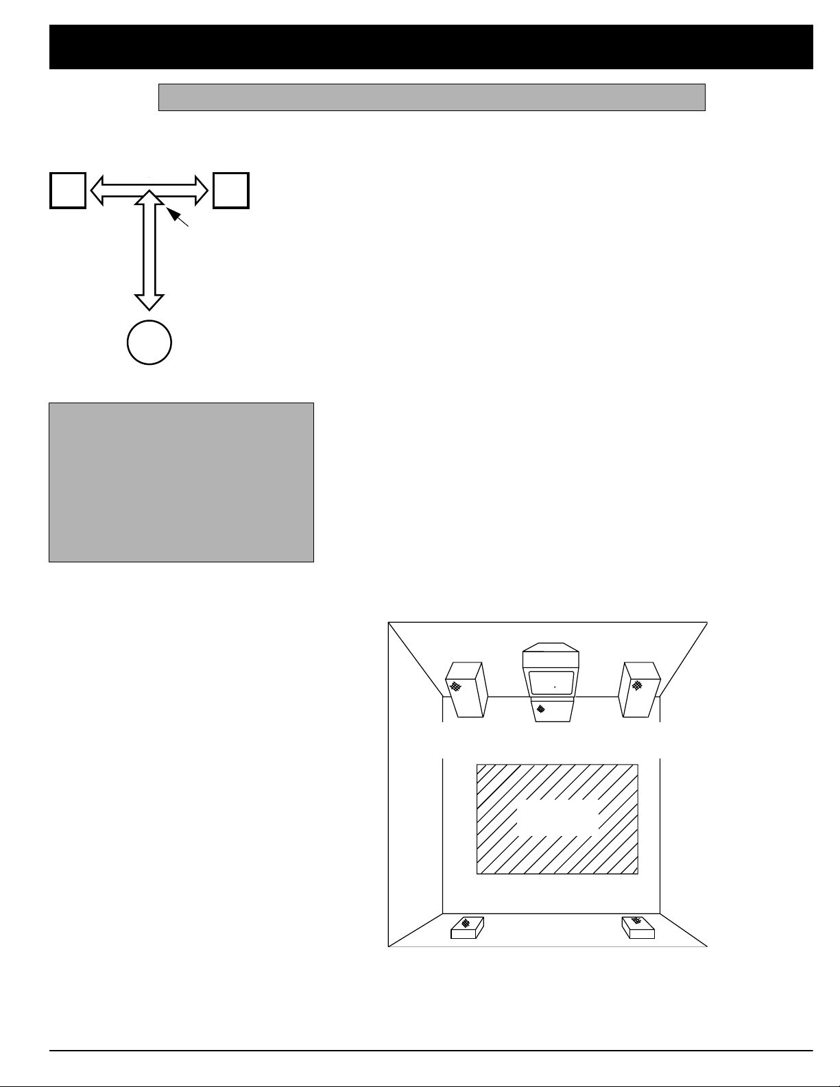
Where you place your speakers (not supplied) can make a noticeable difference
in your system’s sound. The guidelines in this section will help you choose the
best locations. After you use your receiver for a while, you might want to try different locations for your speakers.
Bass response depends largely on speaker location. For strong bass, place the
speakers in the corners of the room. If you want even stronger bass, place the
speakers directly on the floor. If the bass is too strong, move the speakers
slightly away from the corners of the room, or raise them 6 to 18 inches off the
floor. You can buy speaker stands at your local RadioShack store.
The distance between the speakers should be about the same as the distance
between the normal listening point and the point halfway between the speakers.
If you place the speakers too close together, you reduce the stereo separation.
If you place them too far apart, you reduce the bass effect and create a
hole
in
the middle of the sound.
Most speakers have a tweeter dispersion angle of about 60 degrees. Ideally ,
your listening position should be just inside the overlap area of the tweeter dispersion. You can angle the speakers toward you for better stereo effect.
To position your speakers for surround sound, place the front speakers at the
front of your listening area, and place the (rear) surround speakers behind or to
the sides of the listening point (see “Using Advanced Sound Options” on
Page 21). Also, place the center speaker above, below, or behind the TV.
Sound might not appear to coincide with the picture if you place it beside the TV
TV
Front Left
Speaker
Rear Left
Speaker
Center Speaker
Front
Listening
Area
Rear
Front Right
Speaker
Rear Right
Speaker

Preparing Your Receiver
d
onnecting Speakers
Follow these guidelines when you select
and connect speakers.
• Only connect speakers that are rated
at between 8 and 16 Ohms.
• Be sure you properly connect all
speakers.
• Do not connect t wo pairs of speakers
to a single set of terminals at the
same time.
• Realistic, Optimus, and other highquality speakers have color-coded
speaker terminals (red for positive polarity and black for negative polarity).
Use these color-coded terminals as a
guide to help you properly connect the
speakers to the receiver.
• Use 16-gauge (or larger) speaker wire
for all speaker connections, and consider possible speaker locations before you decide how much speaker
wire you need.
Preparing the Speaker Wires
Speaker wire consists of two conductors (individual wires) encased in insulation
and is usually color-coded or marked with a ridge along one side so you can
identify each conductor. Use these markings as a guide to help you properly
connect the speakers to your receiver.
Follow these steps to prepare the speaker wires.
Wire Stran
Wire Strands
Conductor
Speaker Wire
Wire Strands
Conductor
Conductor
1. Cut the speaker wires to the necessary length.
2. Separate the wires about 4 inches on each end.
3. Using a wire stripper, carefully strip about
end of each conductor.
Wire Strands
3
/4 inch of insulation from the
4. Twist the end of each conductor to secure any loose wire strands.
7
L
R
L
R
L
R
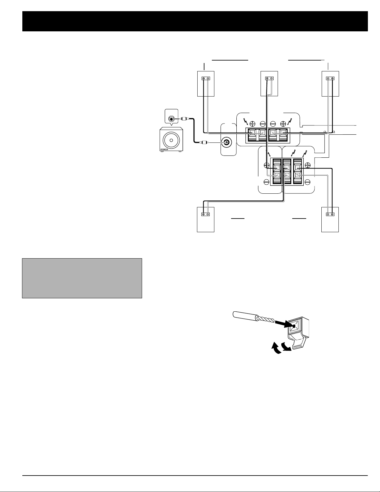
CAUTION:
SPEAKER IMPEDANCE
8 ~ 16 / SPEAKER
CENTER
SPEAKER
SURROUND
SPEAKERS
FRONT SPEAKERS
SUB
WOOFER
PRE
OUT
AUDIO
IN
Amplified
Subwoofer
Preparing Your Receiver
Right Front Speakers Left
Center Speaker
Note:
Be sure you connect the receiver’s right and left positive (+) and
negative (–) terminals to the speaker’s
corresponding right and left positive (+)
and negative (–) terminals.
Right Surround Speakers Left
Connecting the Front Speakers
Follow these steps to connect the right speaker to the receiver’s right
SPEAKERS
1. Press open the receiver’s
2. Press open the receiver’s
3. Connect the ridged or color-coded conductor’s loose end to the right
4. Connect the remaining loose conductor to the right speaker’s negative (–)
terminals.
FRONT SPEAKERS R
(+) red lever and insert the
ridged or color-coded conductor’s end into the small hole. Press the lever
closed to secure the conductor.
FRONT SPEAKERS R (–
) black lever and insert the
other conductor’s end into the small hole. Press the lever closed to
secure the conductor .
speaker’s positive (+) terminal.
terminal.
FRONT
Repeat Steps 1–4 to connect the left speaker to the receiver’s
left terminals.
FRONT SPEAKERS

Preparing Your Receiver
Connecting Su rround-Sound Speakers
You can connect a pair of speakers to the receiver for surround-sound programs. Follow the steps in “Connecting the Front Speakers” to connect the
speakers to the
SURROUND SPEAKERS
terminals.
Connecting the Center Speaker
The center speaker gives additional ambience to surround sound. Follow the
steps in “Connecting the Front Speakers” to connect the center speaker to the
CENTER SPEAKER
terminals.
Connecting a Subwoofer Amplifier
Y our receiver includes a line-level subwoofer output. Connecting a subwoofer to
your system dramatically extends bass response for incredible richness and
depth. When you listen to surround-sound programs, a subwoofer enhances
your home theater experience by realistically re-creating the rumble of an earthquake, the bone-jarring percussion of a cannon, and more. To use the subwoofer output, simply connect
line-level input or to an amplifier to which you have connected a subwoofer.
SUBWOOFER PRE OUT
to an amplified subwoofer’s
RadioShack stores sell a variety of suitable subwoofers and amplifiers.
9
Preparing Your Receiver
PHONO
TAPE2
MONITOR
CD
DVD/
LD
VCR/
TAPE1
SIGNAL GND
IN PLAY
IN OUT
IN OUT
REC IN IN PLAY REC
L
R
L
R
VIDEOINVIDEOINPRE
OUT
CONTROL
OUT
VIDEO
OUT
TO MONITOR TV
VIDEO
OUT
SUB
WOOFER
R
L
OUT PUT
L
R
CD
L
R
REC PLAY
LINE
REC
PLAY
INPUT OUTPUT
L
R
L
R
R
L
R
L
R
L
L
R
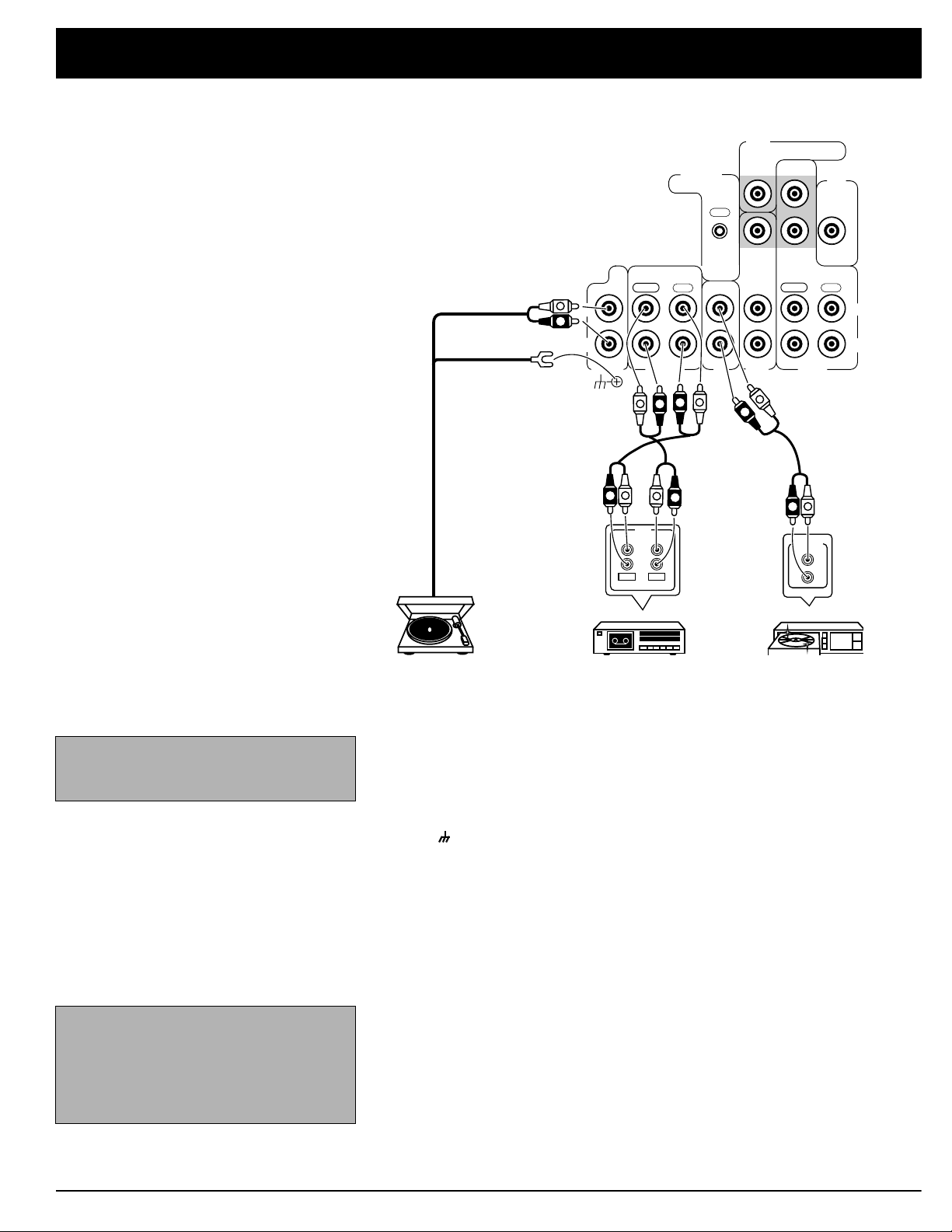
Connecting
Program Sources
You can connect up to five external program sources to your receiver.
Note:
Use shielded audio cables with
phono connectors for all audio connections.
Note:
If you place the c assette deck directly above, below, or to the left of the
receiver, the receiver could interfere with
the cassette deck’s operation. If possible, position the cassette deck to the
right or away from the receiver.
Turntable Cassette Deck CD Player
Connecting a Turntable
Connect a turntable with a magnetic cartridge only. Some older turntables use a
ceramic-type cartridge that does not work with this system.
Connect the turntable’s left and right cables to the receiver’s
PHONO IN
NAL GND
Connecting a CD Player
To connect a CD player to the receiver, connect the CD player’s left and right
output jacks to the receiver’s
Connecting Cassette Decks
You can connect cassette decks to the
Connect the cassette deck’s output jacks to the
MONITOR IN PLAY
TAPE 1
You can connect a third cassette deck (for playback only) to the
(audio) jacks.
OUT REC
L
(left) and R (right)
jacks. Then connect the turntable’s ground wire to the receiver’s
terminal.
L
R CD IN
and
jacks.
VCR/TAPE 1
TAPE 2 MONITOR
and
VCR/TAPE 1 IN PLAY
or
jacks, and connect the cassette deck’s input jacks to the
TAPE 2 MONITOR OUT REC
or
jacks.
DVD/LD IN
SIG-
jacks.
TAPE 2
VCR/
Preparing Your Receiver
CONTROL
OUT
VIDEO
OUT
TO MONITOR TV
VIDEO
OUT
SUB
WOOFER
SIGNAL GND
L
R
PHONO
IN OUT
IN PLAY
VIDEO
VIDEOINVIDEOINPRE
REC IN IN PLAY REC
TAPE2
MONITOR
v
V
IN
R
R
CD
L
AUDIO
OUT
DVD/
LD
L
V
V
VIDEO
OUT
L
R
OUT
IN OUT
VCR/
TAPE1
L
R
AUDIO
REC PLAY
REC
INPUT OUTPUT
L
R
R
R
L
R
PLAY
L
L
L
R
VIDEO
OUT
IN
V
V
V
V
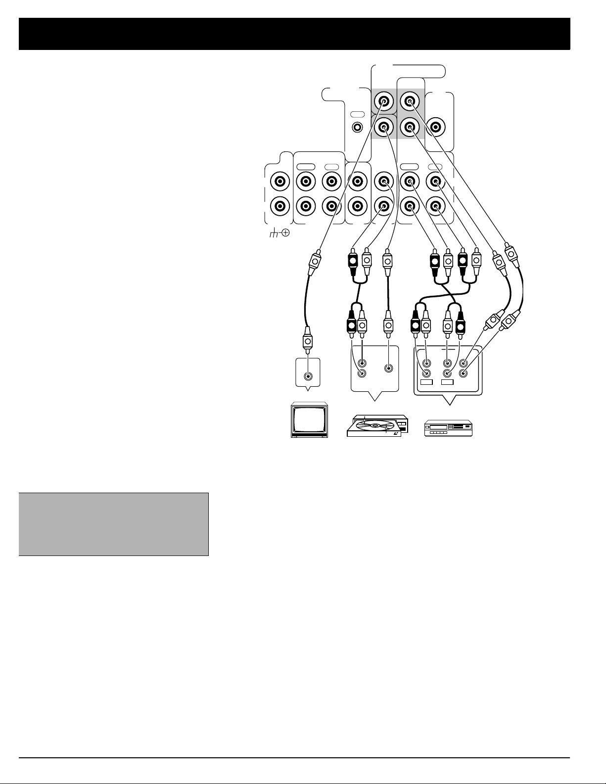
Note:
If your VCR is monaural, use a Yadapter (available at your local RadioShack store) to connect the VCR’s
audio output to both the
and R audio in-
L
puts on the receiver.
VCR
TV Monitor VCRDVD/LD Player
Connecting Video Sources
If you connect two video sources, such as VCRs, laser disc (LD) players, or digital video disc (DVD) players to your receiver, you can use the receiver to select
each video source. You can also use the receiver to easily record from these
video sources to the source connected to
VCR/TAPE 1
.
Connect phono cables from each video source’s audio outputs to the receiver’s
VCR/TAPE 1 IN PLAY
receiver’s
VCR/TAPE 1 OUT REC
or
DVD/LD IN
jacks. Then connect phono cables from the
jacks to the source’s audio input jacks.
Connect video cables from each video source’s video outputs to the receiver’s
VCR/TAPE 1
receiver’s
or
DVD/LD VIDEO IN
VCR/TAPE 1 VIDEO OUT
jacks. Then connect video cables from the
jack to the source’s video input.
Connecting a Video Monitor
The monitor (or TV with baseband video input) you connect to the
minal can monitor any program you connect to the receiver’s
or
DVD/LD IN
TOR TV
jacks. Connect a video cable from the receiver’s
jack to the monitor’s video input.
VCR/TAPE 1 IN PLAY
VIDEO OUT TO MONI-
VIDEO OUT
ter-
10
 Loading...