

Page 1

Flexible Wire-Saving System
S-LINK V
USER’S MANUAL
WUME-SLINKV-9
2020.9
panasonic.net/id/pidsx/global
9th Edition
Page 2

2
Page 3

Contents
Before Using This System ·························5
Introduction ·············································· 6
Warnings ··············································· 6
Instructions for Safe Use ··························· 7
Ambient conditions ······························ 7
Instructions for Use ································ 8
Instructions for Designing ······················ 8
Fail-safe function ································· 8
Conformity to EC Directives ··················· 8
Use with S-LINK system ······················· 8
Instructions for Installation ························· 9
Hook-up cable connectors ····················· 9
Wiring ··············································· 9
Others ··············································· 9
Instructions for Disposal ···························· 9
Designing / Installation Procedures ············· 10
MEMO ··················································12
Chapter 1 ··············································· 13
Designing System ·································· 13
System Conguration ······························· 14
Outline of Design ···································· 16
Selection of Controller or Control board ·······16
I/O Control Points ···································16
Transmission Distance ·····························16
Outputting Error Signals ···························17
Connection of End Unit ····························18
Selection of Control Cable and Connector
Link Cable ·············································18
Control cable selection method:
(For use of
Connector link cable selection method: (For
use of
Making of Branch Lines Using Cable
Connectors ············································19
SL-VCU1
SL-VCU1
only) ··················18
only) ··························18
Power Supply Capacity of System ·············· 20
Calculation of Total Current Consumption
Value ··············································20
Example: Calculation of current consump-
tion ··················································22
Calculation of Voltage Drop Value ··············23
Rated voltage (V) ·······························23
Necessity of Local Power Supply Unit ·········24
Designing of system using local power sup-
ply method ········································24
Connection of DC 2-Wire Output Device to Input
Unit ······················································ 26
Example: Connection of DC 2-wire sensor 27
Transmission Delay Time ·························· 28
Response delay time ···························28
Operation at power-on ·························30
Error signal outputting delay time ···········30
System setting time ·····························31
Selection of Output Holding Function for Output
Unit ······················································ 32
Output holding function setting method ···32
Address Setting ······································ 33
Setting of PLC I/O connector numbers ····33
Setting of I/O unit addresses ·················33
Example: Address setting ····················· 34
Chapter 2 ··············································· 35
Wiring ··················································· 35
Flowchart ·············································· 36
Basic Procedures ···································· 37
Connector hook-up work ······················37
Cutting of exclusive 4-core at cable·······37
How to use exclusive hook-up pliers (SLJPS, SL-JPC, SL-JPE) ························38
Hook-up of Connector ······························39
Hook-up method of SL-JK connector for
cable end and SL-JK1 connector for ‘T’branch ·············································39
Hook-up method of
‘T’ - branch and SL-J3A connector for cable
extension
Hook-up method of
CP3 snap male connectors and
SL-CJ2
Connection to Terminal Block ····················46
Extension of Main / Branch Line Cable ········47
Extension of exclusive 4-core at cables ·47
Extension of cable excluding exclusive
4-core at cables ································47
Extension of cable to I/O device·············47
Installation ·············································48
Installation of each unit ························48
···········································41
snap female connectors ··················44
SL-J1A
SL-CP1, SL-CP2
connector for
SL-CJ1
, and SL-
and
Construction ··········································· 50
Power Supply ····································50
Power supply to system ·······················50
Connection of Each Unit ···························51
Connection of controller ·······················51
Connection of bus direct-connection type
controller and control board ··················52
Connection of PLC I/O Connector ··········53
Connection of I/O unit ··························55
Connection of I/O device ······················56
Connection of main line cable to end unit 57
Connection of local power supply unit ····58
Local power supply to system ···············58
Installation method of batteries ··············59
MEMO ··················································60
Chapter 3 ··············································· 61
Starting System ······································ 61
Flowchart ·············································· 62
Wiring Check ·········································· 64
Check before Starting ··························64
Check of wiring conditions of controller
and control board ·······························64
Check of PLC I/O connectors ················65
Check of cable for short-circuit ··············65
Starting ················································· 66
Power-on (Main Power and Local Power) 66
CONFIG mode ···································66
Check of Recognized Addresses ················70
CHECK mode ····································70
3
Page 4

Chapter 4 ··············································· 71
Specications ········································ 71
Specications ········································· 72
Common Specications ···························72
Address setting switches ······················72
Specications of Each Unit ·······················75
Controller ··········································75
Bus direct-connection type controller for FP2
/ FP2SH Series ··································79
Bus direct-connection type controller for FP7
Series ··············································83
Mitsubishi MELSEC-Q Series PLC bus direct-connection type controller ···············87
Control board ·····································91
Control module ··································95
PLC I/O connector ······························97
I/O unit ··········································· 100
Input terminal ··································· 103
Output terminal ································ 107
Connector input unit ·························· 111
Connector output unit ························ 11 5
MIL connector input unit ····················· 119
MIL connector output unit ··················· 122
Analogue input unit ··························· 125
Analogue output unit ························· 131
Relay output terminal ························ 136
Input module ··································· 139
Output module ································· 141
Picking switch ·································· 143
Picking switch for shutter ···················· 146
Address setting remote controller ········· 149
End unit ·········································· 151
Handy monitor ································· 153
Cable ············································· 157
Hook-up connector ··························· 157
List of programmable logic controllers (PLC)
(upper models) ································· 159
List of Models ········································160
Controller ········································ 161
Control board ··································· 161
Control module ································ 161
List of I/O units ································· 162
List of connectors ····························· 163
Handy monitor ································· 163
Address setting remote controller ········· 163
Others ············································ 164
Selection of connector link cable ·········· 176
Setting of connector numbers, ············· 180
addresses, and number of I/O control points
180
Glossary ········································· 181
FAX Sheet for Asking Question ·················183
MEMO ················································ 184
Chapter 5 ··············································165
Troubleshooting ····································165
Troubleshooting ·····································166
Flowchart for taking corrective action for detected error ····································· 166
Flowchart for power supply condition check
169
How to identify error unit after error detection
171
How to extinguish error indicator ·········· 172
Utilization of output holding function ····· 172
Appendix ··············································173
Appendix ··············································174
List of error numbers ························· 174
Flowchart for error detection ··············· 175
4
Page 5

Before Using This System
5
Page 6
Introduction
S-LINK V
The
highly reliable signal transmissions.
Fully understand the functions and performance of this system before constructing this system.
is a flexible wire-saving that uses our original transmission system to enable high-speed and
This manual provides information necessary for construction of the
Before constructing the
In addition, be sure to observe the cautions, and correctly use the system.
The controllers listed below have their own user’s manuals.
For a detailed description, refer to that documentation.
SL-VGU1-C, SL-VGU1-D : SL-VGU1-C
SL-VGU1-EC
SL-VGU1-485
SL-VMEL-Q
SL-VFP7
For other controllers, refer to the instruction manuals enclosed with the controllers.
EtherCAT® is registered trademark and patented technology, licensed by Beckhoff Automation GmbH,
Germany.
:
:
S-LINK V
SL-VGU1-EC
:
SL-VGU1-485
:
SL-VMEL-Q
SL-VFP7
system, carefully read this manual and fully understand the system.
SL-VGU1-D
/
User’s Manual
User’s Manual
User’s Manual
User’s Manual
User’s Manual
S-LINK V
Warnings
Before Using This System
This manual uses three types of warnings depending on the hazard level. They are ‘
CAUTION
‘
.’ To safely use the
S-LINK V
system, be sure to observe these warnings.
DANGER
exible wire-saving system.
DANGER
WARNING
,’ ‘
,’ and
Remarks
DANGER
‘
word is limitedly used in the extremely hazardous situations.
’ indicates that mishandling of this system may result in death or serious injury, and this
WARNING
WARNING
‘
’ indicates that mishandling of this system may result in death or serious injury.
CAUTION
CAUTION
‘
NOTE
’ indicates that mishandling of this system may result in injury or damage of the system.
‘NOTE’ provides caution or information to you in order to prevent operation errors.
1) Panasonic Industrial Devices SUNX Co., Ltd. holds the copyright of this document. For this reason, do not
copy this document without our permission.
2) The contents of this document may be subject to change without prior notice for the reasons of improvement.
3) The product specications shown in this document were determined in September 2020.
6
Page 7
Instructions for Safe Use
WARNING
S-LINK V
The
safety function. For this reason, do not use the
fect human lives or assets.
Even if this system is not used as an accident preventive system or safety system, if this system is
used for a nuclear power control system, railroad facility, aviation facility, vehicle, combustion system,
medical equipment, or the like, be sure to design a system having enough capacity, and adopt safety
measures for the system, such as a fail-safe function. In addition, please contact our sales division.
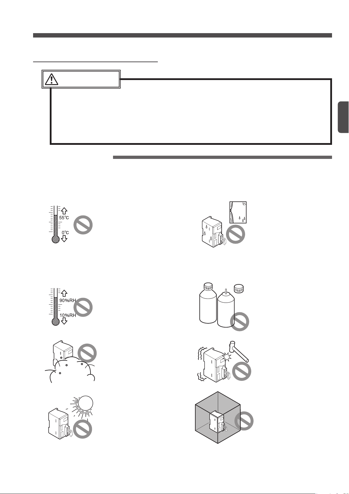
Ambient conditions
Do not use this system at the following places:
system does not have any control functions, such as accident preventive function and
Place where the ambient tem-
perature is out of the specied
range of 0 to +55°C (Note 1)
Notes:
1) The optimum ambient temperature depends on the product
type. For this reason, check
the specications of this product shown in Chapter 4.
2) If this product is incorporated
in the control box together with
the other unit, the unit may
generate heat to change the
ambient temperature. In this
case, install a cooling fan so
that the ambient temperature
cannot exceed the rated upper
limit temperature.
S-LINK V
Introduction
system if malfunction of the system may af-
Before Using This System
Place where the ambient temperature extremely varies and
dew condensation may be
caused.
Place where the ambient humidity is out of the specified
range of 35 to 85% RH (Note)
Note
The optimum ambient humidity
depends on the product type. For
this reason, check the specifications of this product shown in
Chapter 4.
Steamy or dusty place or
place near water, oil, or
chemical source
Place where direct sunlight
may enter
COR-
ROSIVE
GAS
FLAM-
MABLE
GAS
Place where there is a corro-
sive or ammable gas
Place where vibration or
shock of more than the specied level may be directly applied to the system main body
Closed place
However, if a ventilation
hole or a fan is installed,
such a place can be
used.
7
Page 8

Instructions for Use
Note:
supply unit and the surge absorber. Check whether a resistor is needed.
+24V DC
Recommended part: ERZV05D390 manufactured by Panasonic Corporation (Note)
Not good
Good
Instructions for Designing
Fail-safe function
CAUTION
Disconnection of a signal line, instantaneous power failure, or abnormal signal may cause a problem.
For this reason, please adopt a fail-safe function for the entire system by yourself.
To ensure safety, be sure to incorporate the interlock circuit, limit circuit, or the like, in the external circuit excluding the
S-LINK V
system circuit.
To incorporate the
Regarding the fail-safe function, if you have an unclear or doubtful point, please contact our sales division.
S-LINK V
system in your equipment, be sure to adopt a fail-safe function.
Conformity to EC Directives
WARNING
● Each unit of the
Before Using This System
To conform to the EC Directives, the
as EN 61000-6-4 of the EMI standard and EN 61000-6-2 of the EMS standard. When you incorporate the
tem in your machine or equipment, check that the wiring condition conforms to the requirements of the EC Directives.
To use the
tric Corporation and to conform to the requirements of the EMC Directive, install the system in accordance with
the PLC User’s Manual prepared by Mitsubishi, and be sure to observe the following items:
● Be sure to put the PLC and the
●
Be sure to ground the shielded cable that connects the PLC to the
● If the shielding eect is not enough, install a ferrite core.
the system, check that entire system can conform to various standards.
● The lightning surge preventive function is not adopted for the I/O module (
conform to the requirements of EN 61000-6-2, incorporate the following circuit in your board.
Power supply
● If it is not necessary for the relay output terminal (
use of 250V AC, 3A is possible.
SL-VGU1-C
S-LINK V
If a different part is used, a resistor may be needed between the power
together with the PLC (programmable logic controller) manufactured by Mitsubishi Elec-
series conforms to various standards. However, to incorporate a unit in
+
–
Surge absorber
S-LINK V
SL-VGU1-C
SL-VM
0V
SL-VTPR4/8
system is tested in accordance with the EMC Directive standards, such
in a conductive box.
SL-VGU1-C
) to conform to the EC Directives,
in the 300mm area of the
□ /
VMP
□). To
S-LINK V
SL-VGU1-C
sys-
.
Use with S-LINK system
S-LINK V
The
mal operation or damage. Separately construct the
However, if gateway controllers are used as the child station of the open network (CC-Link, DeviceNet, RS-485 /
RS-232C, EtherCAT), 2 systems can be used together on the same network.
8
system cannot be used together with the
S-LINK V
gateway
controller
S-LINK V
unit
S-LINK
unit
S-LINK
S-LINK V
system. Use with a system may cause abnor-
system and the
S-LINK V
gateway
controller
S-LINK V
unit
S-LINK
S-LINK V
unit
system.
S-LINK
gateway
controller
S-LINK
unit
S-LINK
unit
Page 9

Instructions for Installation
CAUTION
● Select a power supply unit equipped with the short-circuit protective function (fuse, etc.).
● The power of the
the main cable or I/O device side. However, the short-circuit protective function is not adopted for
this power supply circuit. For this reason, adopt a short-circuit protective function, such as a fuse,
for the power supply circuit.
● Take care that wrong wiring will damage the product.
● Before starting the following works, be sure to turn o the power of the PLC (programmable logic
controller), personal computer main body,
of the I/O device.
• Machine assembly (installation)
• Removal or reinstallation of a
• Cable connection
• Address setting / change
● Before handling this product, remove any electrostatic charge that may be present on your body.
There is a danger of this product getting damaged due to the electrostatic charge.
S-LINK V
system passes through the inside of each unit and is then supplied to
S-LINK V
S-LINK V
unit or connection of I/O device
units, and also turn o the power supply unit
Instruction for Use
Before Using This System
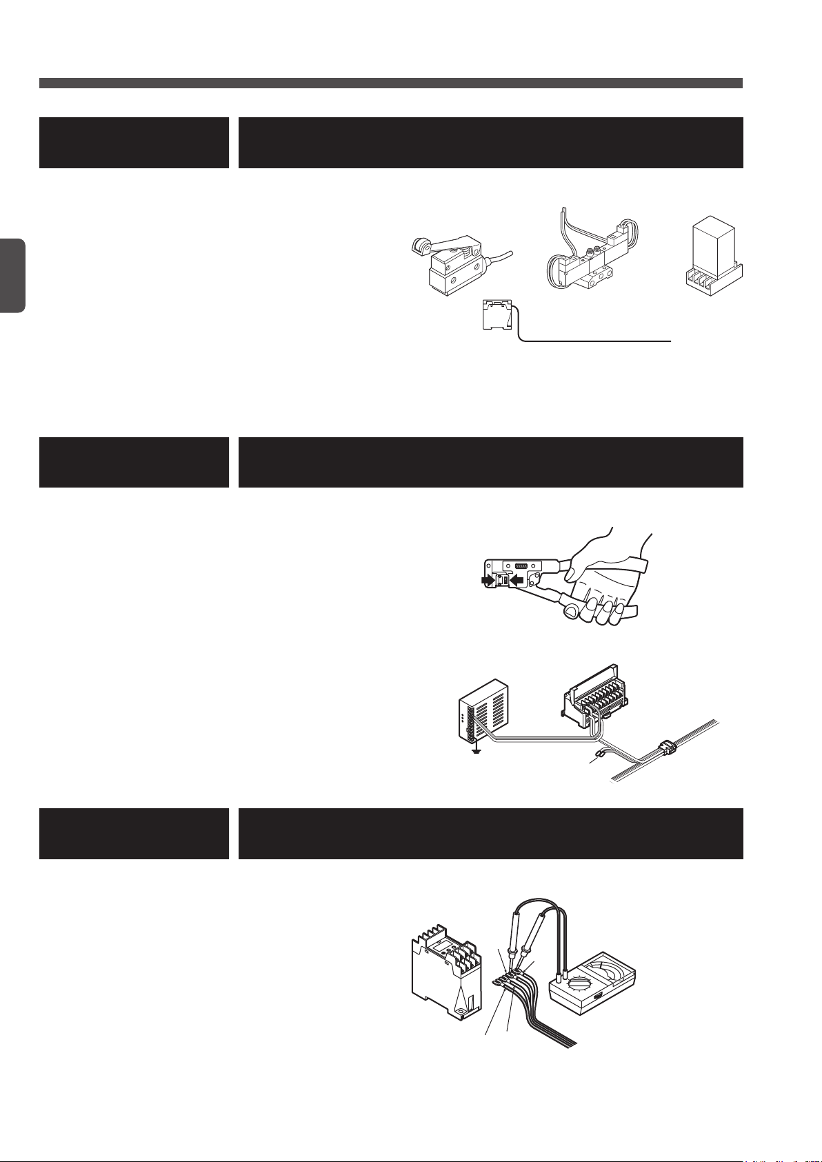
Hook-up cable connectors
To hook-up an exclusive cable connector, use the exclusive tool, and correctly hook-up the connector by follow-
ing the procedure specied in this manual.
If a connector is not correctly hooked-up, the
In addition, observe the following items:
● After checking the cable type and the purpose, select the right type of connector.
● Before hook-up a connector, be sure to check the colors of cables to be connected.
● Use the exclusive hook-up pliers (
For the hook-up procedure of each connector, refer to pages 37 to 45.
● If a connector is once hooked-up, do not reuse the connector.
The performance of such a connector may be deteriorated.
SL-JPS, SL-JPC
S-LINK V
system will not operate.
SL-JPE
or
) to hook-up the connectors.
Wiring
Observe the following items to distribute cables:
● Keep cables away from the power line and the high-voltage line.
● Do not completely fold down any cables.
● Do not pull any cables with a strong force.
● Do not apply any weight to any cable.
● Do not touch a cable to any other system cables.
This is because signals of dierent systems may interfere with each other.
● Do not bend cables many times.
● Wind insulation tape on the end of each cable, if necessary.
Others
● Apply the specied torque to tighten terminal screws of each unit.
● Check the connectors for looseness.
● Do not disassemble or modify this product.
Instructions for Disposal
● Request a waste disposal company to dispose of this product.
9
Page 10
Designing / Installation Procedures
Local power supply unit
Chapter 1 Designing System
● Determine the system design.
● Determine the necessary number of I/O points for
the I/O device.
● Determine the cable length necessary for transmis-
sion.
● Select the transmission speed.
● Set the address.
● Calculate the power supply capacity of the system.
● Determine the connection method for the input de-
vice of DC 2-wire output type.
● Determine the transmission delay time.
● Set the output holding function.
How long?
Chapter 2 Wiring
Before Using This System
● This chapter describes the wiring methods to be used for actual installation.
● Caution regarding cutting of exclusive 4-core flat
cable
● Connector hook-up method
● Cable extension method
● Connection to I/O device
● Connection of local power supply unit
● Connection to terminal block
ON
256
128
16
ADDRESS
8
4
2
1
+
-
AC
F.G.
Insulated
Chapter 3 Starting System
● Check the system before starting.
● Check the cable for short-circuit.
● Check the system before starting.
● Caution regarding power-on
● Description of CONFIG mode
● Description of CHECK mode
10
D
(White)
+24V (Brown)
0V (Blue)
G
(Black)
Transmission cable
Analogue tester
Page 11

Designing / Installation Procedures
Chapter 4 Specications
● Select
S-LINK V
●
S-LINK V
●
S-LINK V
●
S-LINK V
control units
input units
output units
units optimum for the purpose of your system.
● Hook-up connector
● Exclusive 4-core at cable
Chapter 5 Troubleshooting
● This chapter describes how to solve the problem if the
not operate properly.
● Troubleshooting after error indication
● Power supply check procedure
● How to extinguish the error indicators
7
6
5
4
3
2
1
0
S-LINK V
1
Before Using This System
system does
Appendix
● List of error numbers
● Flowchart for error detection
● Selection of connector link cable for PLC
● Fax sheet for asking questions
This manual is prepared for the designer and the installer of the
mon to both the designer and the installer:
Before Using This System
●
Chapter 4 Specications
● ‘
Chapter 5 Troubleshooting
● ‘
Appendix
●
In addition, the designer should refer to ‘
Chapter 2 Wiring
‘
’ and ‘
’
’
Chapter 1 Designing System
Chapter 3 Starting System
.’
S-LINK V
system. The following items are com-
,’ and the installer should refer to
11
Page 12

MEMO
Before Using This System
12
Page 13

Chapter 1 Designing System
13
Page 14
4
3
2
1
0
7
6
5
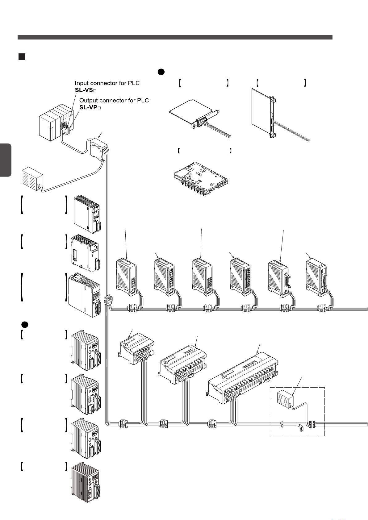
Example of system configuration
An example of the S-LINK V system is shown below.
For the specifications of each unit, refer to Chapter 4.
Controller
SL-VCU1
Power supply
unit
24V DC
+10
– 5
%
Bus direct-connection
type S-LINK V
controller for
MELSEC-Q series PLC
manufactured by
Mitsubishi Electric Corp.
SL-VMEL-Q
Bus direct-connection
type S-LINK V
controller for FP2 /
FP2SH series
SL-VFP2
Gateway controller (Note)
Control board
S-LINK V control board
for VME bus
SL-VVMES2
S-LINK V control board
for PCI bus
SL-VPCI
S-LINK V control module
SL-VMC1
4-channel connector
output unit
SL-VTP4J
e-CON type 4-channel
connector output unit
SL-VTP4E
e-CON type 8-channel
connector output unit
SL-VTP8E
8-channel connector
output unit
SL-VTP8J
16-channel MIL
connector
output unit
SL-VTP16C1(-S)
Analog output unit
SL-VTDA1
4-channel output terminal
SL-VTBP4
8-channel output terminal
SL-VTBP8
16-channel output terminal
SL-VTBP16
32-channel output terminal
SL-VTBP32
Local power
supply unit
4-channel relay output
terminal SL-VTPR4
S-LINK V gateway
controller for CC-Link
SL-VGU1-C
S-LINK V gateway
controller for
RS-485
/ RS-232C
SL-VGU1-485
S-LINK V gateway
controller for EtherCAT
SL-VGU1-EC
S-LINK V gateway
controller for DeviceNet
SL-VGU1-D
Bus direct-connection
type S-LINK V
controller for FP7 series
SL-VFP7
System Conguration
Chapter 1
14
Note: For a detailed description of the following controllers, refer to their respective user’s manuals.
SL-VGU1-C, SL-VGU1-D
SL-VGU1-EC
SL-VGU1-485
SL-VMEL-Q
SL-VFP7
:
:
:
:
SL-VGU1-C
:
SL-VGU1-EC
SL-VGU1-485
SL-VMEL-Q
SL-VFP7
SL-VGU1-D
/
User’s Manual
User’s Manual
User’s Manual
User’s Manual
User’s Manual
Page 15

1
2
3
4
4
3
2
1
0
7
6
5
Analog input unit
SL-VTAD1
I/O module
Input module
SL-VM8 / VM16
Output module
SL-VMP8 / VMP16
Hook-up connectors
SL-CP3
Cables and hook-up connectors
Flat cables are available so that
'T' - branch can be easily formed
by using hook-up connectors.
There are various types of hook-up connectors
that enable easy connection of cables.
Handy monitor
SL-VHM1
Picking switch
SL-VPK01 SL-VPK02
For flexible wire-saving system
e-CON type 4-channel
connector input unit
SL-VT4E
e-CON type 8-channel
connector input unit
SL-VT8E
4-channel connector
input unit SL-VT4J
16-channel
MIL connector
input unit
SL-VT16C1
8-channel connector
input unit SL-VT8J
1-channel output unit
SL-VCH11
2-channel output unit
SL-VCH22
1-channel input unit
SL-VCH10
2-channel input unit
SL-VCH20
2-channel I/O mixed unit
SL-VCH21
4-channel relay output
terminal SL-VTPR4
8-channel relay output
terminal SL-VTPR8
8-channel input terminal
SL-VTB8
4-channel input terminal
SL-VTB4
16-channel input terminal
SL-VTB16
32-channel input terminal
SL-VTB32
End unit
SL-VEU
System Conguration
Chapter 1
15
Page 16

Outline of Design
A
Transmission distance =
Selection of Controller or Control board
Select a
computer, VME bus computer, open network).
S-LINK V
controller or a
S-LINK V
control board optimum for the upper machines (PLC, PC, PCI bus
I/O Control Points
The system needs the following I/O control points. Design the system considering these points.
● Each controller or control board can control up to 256 nodes (number of I/O units connected to the system)
and 512 points (512 points × 2 for the
SL-VVMES2
● To cope with various PLC connection types of various manufacturers, we can provide 8 types of PLC input
connectors and 7 types of PLC output connectors. For a detailed description, refer to pages 159 and 160.
Each PLC I/O connector has 32 points for any model.
Chapter 1
NOTE
) of I/O device, connect two or more controllers as the other systems.
Each system needs one controller or one control board.
Two or more controllers or control boards cannot be connected to one system.
The above described number of I/O control points (512 points or 512 points × 2 for the
SL-VVMES2
This means that these values depend on the total cable length and the conditions of the connected machine (total current consumption, voltage drop, etc.).
For a detailed description, refer to pages 16 to 25.
) and the number of nodes (256 nodes) are the maximum values.
SL-VVMES2
). To control more than 512 points (512 points × 2 for the
Transmission Distance
The following two types of cables can be used for the
● Exclusive 4-core at cable (recommended cable)
● 4-core VCTF cable (0.3 to 2.0mm2, non-shielded) commercially available
Note: The VCTF cable is the vinyl cabtyre cable that conforms to the requirements of JIS C 3306 ‘Polyvinyl chloride insulated exible cords.’
To wire the
(+24V, 0V) and 2 signal transmission lines (D, G).
The cable length depends on the total cable length and the transmission distance.
S-LINK V
Control area
system, use 4-core cables so that the wire system can consist of 2 power supply lines
: S-LINK V I/O unit
(Branch line) (Branch line)
B C D
S-LINK V
(Main line)
A
system.
(Branch line)
16
Total cable length =
+
A
+B+
D
C
Page 17

Outline of Design
NOTE
● The main line is the longest route distributed from the controller or control board.
● The branch lines are the routes branched from the main line.
The total cable length should satisfy the conditions shown in the following table:
Transmission mode Total cable length (m)
A 100
B 400
C 1,600
The maximum transmission distance (between D and G) is as follows:
Mode A: 50m
●
The maximum length is 50m regardless of the cable conductor cross section (0.3 to 2.0mm2) and the number
of nodes (1 to 256 nodes).
Mode B
●
Conductor
cross
section
(mm2)
0.3 180
0.5
0.75
1.25
2.0
Number of nodes and maximum transmission length (m)
Up to 224 nodes Up to 256 nodes
200 (full specication for mode B)
Chapter 1
Mode C
●
Conductor
cross
section
(mm2)
0.3 570 440 350 300 260 220 200 180
0.5 710 580 490 420 370 330 300
0.75 780 670 590 530 480
1.25
2.0
NOTE
Up to 32
nodes
Up to 64
nodes
● Voltage drop between +24V and 0V is not considered. For this reason, calculate this volt-
age drop value, and use a local power supply unit, etc. to prevent voltage drop.
Number of nodes and maximum transmission length (m)
Up to 96
nodes
For a detailed description, refer to page 23.
● The conductor cross section of the exclusive 4-core at cable
● Wire the
S-LINK V
system while observing the communication distance specications de-
scribed above. In addition, use the cables that satisfy the specications described above.
● To select applicable cables, refer to the section describing cables.
For a detailed description, refer to page 157.
● The picking switch
SL-VPK0
Outputting Error Signals
Up to 128
nodes
800 (full specication for mode C)
Up to 160
nodes
Up to 192
nodes
SL-RCM
Up to 224
nodes
□ is 0.5mm2.
□ cannot be used in mode A (transmission mode).
Up to 256
nodes
If the controller is equipped with the error signal output function, the controller can output an error signal after
detection of an error.
To output an error signal, the
S-LINK V
system will be turned on properly. If an error occurs, the NPN output
transistor will be turned o.
For each type of error, you can select whether the error signal should be output.
For the Troubleshooting, refer to page 165.
For the error, refer to page 166.
17
Page 18

Outline of Design
Same length (Note 1)
Connect the end unit to the line
Main line
Connection of End Unit
CAUTION
Each system needs at least 1
not operate properly.
If the cable lengths are the same, connect the end unit to the line having fewer nodes (units).
Be sure to connect 1
If the branch line length exceeds 80% of the maximum transmission distance, connect 1
of the branch line, too.
Up to 2
<If the branch line length is equal to the main line length>
SL-VEU
SL-VEU
end units can be connected for 1 system.
end unit to the end of the main line.
SL-VEU
end unit. If the
SL-VEU
SL-VEU
unit is not connected, the system may
Chapter 1
having fewer nodes.
<If the branch line length is 80% of the main line length or more>
Maximum transmission distance
SL-VEU
SL-VEU
unit to the end
Connect the end unit to the main line
and branch line, respectively.
80% of the main line length or more
Notes: 1) The maximum transmission distance depends on the cable conductor cross section and the number of nodes.
For the maximum transmission distance, refer to page 17.
2) Even if the cable lengths are the same, if both the main and branch line lengths exceed 80% of the maximum transmission distance, connect two
SL-VEU
end units.
Selection of Control Cable and Connector Link Cable
Control cable selection method: (For use of SL-VCU1 only)
Check the distance from the
SL-VC1000
One control cable is needed for every 8 PLC I/O connectors.
(1m long) or
Connector link cable selection method: (For use of SL-VCU1 only)
The PLC I/O connector installation direction (vertical) and layout depend on the PLC manufacturers.
Check the connection distance of the PLC I/O connector, and then select the applicable connector link cable:
SL-VF70
For a detailed description, refer to page 176.
(70mm),
SL-VF150
SL-VCU1
SL-VC2000
(150mm), or
to the PLC I/O connector, and then select the applicable control cable:
(2m long).
SL-VF250
(250mm).
18
Page 19

Making of Branch Lines Using Cable Connectors
SL-VCU1
Intermediate connector
SL-JK
Branch lines can be made by using connectors and terminal blocks.
In addition, for this product, cables or connectors that are commercially available can be used.
CAUTION
The exclusive hook-up connectors can connect the exclusive 4-core at cables only.
Outline of Design
Exclusive 4-core at cable
Making of ‘T’ - branch line using exclusive hook-up
connector
SL-J1A
…1
Extension using exclusive hook-up connector
Exclusive 4-core at cable
4-core VCTF cable
commercially available
(non-shielded) (Note)
Note: The VCTF cord is the vinyl cabtyre cord that conforms to the requirements of JIS C 3306 ‘Polyvinyl chloride insulated exible cords.’
SL-J3A
…2
Connection of branch line using exclusive hook-up
connector
SL-JK1
SL-JK
Intermediate connector commercially available…5
Intermediate terminal block commercially available…6
and
and
SL-CP3
SL-CP3
…3
…4
SL-J1A
4-core VCTF cable commercially available (non-shielded) (Note)
Intermediate connector commercially available or
intermediate terminal block commercially available
Intermediate connector commercially available or
intermediate terminal block commercially available
Note: Use the same diameter cable.
1
6
SL-J1A
1
Intermediate connector
Intermediate terminal block
SL-CP3
3
SL-J3A
2
5
Chapter 1
SL-CP3
4
SL-JK1
SL-VEU
19
Page 20

Power Supply Capacity of System
This section describes how to calculate the total current consumption value and voltage drop value in order to
determine the power supply capacity (capacity of 24V DC power supply unit).
Calculation of Total Current Consumption Value
To determine the total current consumption, check the current consumption of each I/O unit.
Calculate the power supply capacity while referring to the list of current consumption values shown below.
Designation Model No. Current consumption (mA)
Controller
Bus direct-connection
Bus direct-connection
Mitsubishi MELSEC-Q PLC bus direct-connection
Control board for PCI bus
Control board for VME bus
Control module
Gateway controller for CC-Link
Gateway controller for DeviceNet
Gateway controller for RS-485 / RS-232C
Gateway controller for EtherCAT
Input connector for PLC
Chapter 1
Output connector for PLC
End unit
1-channel input unit
2-channel input unit
2-channel I/O mixed unit
1-channel output unit
2-channel output unit
4-channel connector input unit
8-channel connector input unit
16-channel MIL connector input unit
Analogue input unit
8-channel input module
16-channel input module
4-channel connector output unit
8-channel connector output unit
16-channel MIL connector output unit
Analogue output unit
8-channel output module
16-channel output module
4-channel relay output terminal
8-channel relay output terminal
Picking switch
Picking switch for shutter
Handy monitor
S-LINK V
S-LINK V
controller for
controller for
FP2
FP7
FP2SH
/
series
S-LINK V
series
controller
SL-VCU1
SL-VFP2
SL-VFP7
SL-VMEL-Q
SL-VPCI
SL-VVMES2
SL-VMC1
SL-VGU1-C
SL-VGU1-D
SL-VGU1-485
SL-VGU1-EC
SL-VS
□ 30
SL-VP
□ 73
SL-VEU
SL-VCH10
SL-VCH20
SL-VCH21
SL-VCH11
SL-VCH22
SL-VT4J, SL-VT4E
SL-VT8J, SL-VT8E
SL-VT16C1
SL-VTAD1
SL-VM8
SL-VM16
SL-VTP4J, SL-VTP4E
SL-VTP8J, SL-VTP8E
SL-VTP16C1(-S
SL-VTDA1
SL-VMP8
SL-VMP16
SL-VTPR4
SL-VTPR8
SL-VPK01
SL-VPK02
SL-VHM1
) 50 (Note 2)
25 (when shutter operation: 450)
135
60
80
70
85
88 (Note 1)
60
300
300
300
300
10
20
28
24
16
20
70 (Note 2)
105 (Note 2)
80 (Note 2)
80
18
20 (Note 2)
60 (Note 2)
90 (Note 2)
90
60
95 (Note 2)
90 (Note 2, 3)
150 (Note 2, 3)
25
500
20
Page 21

Power Supply Capacity of System
Designation Model No.
4-channel input terminal
8-channel input terminal
16-channel input terminal
32-channel input terminal
4-channel output terminal
8-channel output terminal
16-channel output terminal
32-channel output terminal
Notes: 1)
2) Regarding the
For a detailed description, refer to the specications of each product shown in
3) The
For the characteristics of the product when using PhotoMOS relay, refer to the ‘
4) The value shown in the ‘Unit side’ area indicates the current consumption in the main circuit.
The value shown in the ‘I/O side’ area indicates the current consumption in the I/O circuit.
SL-VVMES2
range, turning on of all the points may not be possible.
https://panasonic.net/id/pidsx/global
NOTE
, the value for 1 port is shown in the above table.
SL-VTPR
SL-VTPR
□ limits the output current depending on the ambient operation temperature and the number of ON points.
SL-VT□J, SL-VT□E, SL-VT□16C1(-S
□,
.’
The values shown in the above table does not include the current supplied to the PLC module and current consumption of sensors and loads.
SL-VTB4
SL-VTB8
SL-VTB16
SL-VTB32
SL-VTBP4
SL-VTBP8
SL-VTBP16
SL-VTBP32
SL-VM□16,
), and
if the ambient temperature is not in the specied
Specications
Panasonic Industrial Devices SUNX website:
In addition to the above units, when additional units (products) are connected, such as the
3-line sensor and output load, to the same 24V DC power supply unit, add the current consumption values of the additional units to the power supply capacity value.
Current consumption (mA)
Unit side I/O side (Note 4)
25 45
30 75
35 150
45 300
25 40
30 60
40 100
45 180
.
Chapter 1
21
Page 22

Power Supply Capacity of System
Input connector for PLC
8-channel connector input unit
SL-VTP4J
Example: Calculation of current consumption
<System conguration for control of 8 sensors and 4 output loads>
SL-VS1
Chapter 1
Controller
End unit
Input connector for PLC
Output connector for PLC
8-channel connector input unit
4-channel connector output unit
8-channel input terminal
Sensors
(Average current consumption: approx. 30mA )
Output loads
(Average current consumption: approx. 20mA )
Power supply unit
SL-VT8J
Designation Model No. Qty Current consumption (mA)
Output connector for PLC
SL-VP1
Controller
SL-VCU1
Sensors
4-channel connector output unit
SL-VCU1
SL-VEU
SL-VS1
SL-VP1
SL-VT8J
SL-VTP4J
SL-VTB8
—
—
1 135
1 10
1 30
1 73
1 105
1 60
1 30 + 75 = 105
8 30 × 8 = 240
4 20 × 4 = 80
Total 838
8-channel input terminal
SL-VTB8
Sensors
End unit
SL-VEU
Output loads
22
Page 23

Calculation of Voltage Drop Value
8
60
Allowable passing
Ambient temperature (˚C)
Power Supply Capacity of System
The transmission cables of the
cables themselves. For this reason, calculate the voltage drop value between +24V and 0V, and supply the rated voltage to all the
and G, and that of the control cables and connector link cables.
S-LINK V
S-LINK V
I/O units. However, it is not necessary to consider the voltage drop between the D
system may cause voltage drop due to the conductor resistance of the
CAUTION
Use of a longer cable will cause more voltage drop. If the voltage drops below the rated voltage, the
I/O units will not work. In this case, use the local power supply unit.
Elongation of the transmission distance will cause more voltage drop
at the line end (between +24V and 0V).
Voltage drop (V) = Cable length (m) × 2 × conductor resistance (Ω/m) × current (A)
Relation between the ambient temperature and allowable passing current when exclusive S-LINK V
cable SL-RCM100□ / RCM200 or SL-CBM100 / CBM200 (conductor cross section = 0.5mm
cable) is used.
2
for each
Chapter 1
Rated voltage (V)
CAUTION
The rated voltage depends on the unit. Check the rated voltage, and then select the right power supply unit and cables.
Supply the rated voltage to each unit.
Since the rated voltage to be supplied to the controller is +24V (-5%), the voltage supplied to the con-
●
troller should not be dropped below the following value:
24 - (24 × 0.05) =
Since the rated voltage to be supplied to the I/O units and end unit is +24V (-10%), the voltage sup-
●
plied to these units should not be dropped below the following value:
24 - (24 × 0.1) =
22.8V
21.6V
7
6
5
4
current (A)
0
5 10 15 20 25 30 35 40 45 50 55
23
Page 24

Power Supply Capacity of System
Necessity of Local Power Supply Unit
The 24V DC power supply unit that drives the system uses either the centralized power supply method (use of
only one power supply unit) or the decentralized power supply method (use of additional local power supply unit)
to supply power to each unit.
At rst, calculate the total current consumption value (sum total of current consumption values of all units ‘+’ sum
total of load current values of I/O devices).
After that, from the obtained calculation result, cable length, and conductor resistance, calculate the voltage
drop value, and determine the voltage to be supplied to each unit.
If the voltage supplied to each unit is above the rated voltage (22.8V or more for the controller, 21.6V or more for
the I/O unit), you can design the system using the centralized power supply method.
If the voltage supplied to a unit is out of the rated voltage range, connect a local power supply unit, and use the
local power supply method.
Designing of system using local power supply method
Chapter 1
CAUTION
To use a local power supply unit, turn on the local power supply unit rst, and then turn on the main
power supply unit, or turn on these power supply units at the same time.
If the main power supply unit is turned on rst, the system may not operate properly.
In the following cases, connect a local power supply unit:
● The communication distance is too long, and voltage drop is too large.
For this reason, it is not possible to supply the rated voltage to the I/O units.
● A 2-core cable is used for connection of the I/O unit (for the D-G line only).
● The main power supply unit and the local power supply unit should be the small capacity type.
● An I/O device that generates a large noise should be used.
<Reference value>
Conductor cross section (mm2) Conductor resistance (Ω/m)
0.3 Approx. 0.065
0.5 Approx. 0.040
0.75 Approx. 0.025
1.25 Approx. 0.015
2.0 Approx. 0.010
Notes: 1) The conductor resistance values shown in the above table are reference values.
To determine the conductor resistance values for the actual cables, contact the cable manufacturer.
2) The conductor cross section of the exclusive 4-core at cable should be 0.5mm2.
To determine whether a local power supply unit is necessary, refer to the owchart shown on the next page.
24
Page 25

Proposed system construction plan
Calculation of total current consumption value (refer to page 22)
Power Supply Capacity of System
ReexaminationReexamination
A unit should be changed
or removed
Out of rated range
of cable connector
(refer to page 157)
Calculation of voltage drop value
(refer to page 23)
Yes
A unit should be changed
or removed
A local power supply unit
is needed in view of the calculated
voltage drop value
Yes
No
Yes
Chapter 1
No
No
Necessary
Unnecessary
Decision 1
The I/O device should be
connected using 2-core cable
(for the D-G line only)
No
Decision 2
The main power supply unit and local
power supply machine should be the
small capacity type
No
Decision 3
An I/O device generates
large noise
No
Centrailzed power supply method Local power supply method
Yes
Yes
Yes
25
Page 26

Connection of DC 2-Wire Output Device to Input Unit
CAUTION
If you have to connect a DC 2-wire output device to an input unit, recommend our product.
If a product manufactured by another company is used, the conditions should be checked by follow-
ing the procedure shown in the following owchart.
This is because the output device of another company does not t our input unit.
DC 2-wire output device should be
used
Chapter 1
Our product is used
Check 1
21.6V-V
=In specied op-
THON
21.6V-V
THOFF
eration voltage range
Check 2
A
21.6V-V
≥
Minimum load current
i
R
Condition A
NO
≥ VA and
YES
YES
YES
NO
Connection to the
is not possible
NO
RB1 ≤
Normal connection
S-LINK V
system
The bleeder resistance is necessary
Calulation of bleeder resistance
A
21.6V-V
Minimum load current-
21.6V-V
i
R
Condition B
VA : Residual voltage in ON mode
A1 : Leakage current
VTH : Input voltage of input unit
THON
V
: Input unit ON voltage
THOFF
V
: Input unit OFF voltage
Ri : Input impedance
RB : Bleeder resistance
A
Check 3
THOFF
V
≥ A1 (Leakage current
i
R
in OFF mode)
YES
Decision of condition
Condition A
Connection is possible without any
bleeder resistor
26
NO
Condition B
Calulation of bleeder resistance
RB2 ≤
A1-
V
THOFF
i
R
THOFF
V
Decision of condition
Condition A
Connection is possible if the RB2
bleeder resistor is attached
Connection is possible if the RB1
bleeder resistor is attached
Condition B
Connection is possible if the RB1 or RB2
(small value) bleeder resistor is attached
Page 27

Connection of DC 2-Wire Output Device to Input Unit
21.6V - VA of DC 2-wire input device
R1
21.6V-3V
3.3kΩ 3.3kΩ
18.6V
3.3kΩ
4V
V
≥ 0.8mA
+24V
Input device
S-LINK V input unit
Example: Connection of DC 2-wire sensor
To connect DC 2-wire proximity sensor GX-12MU to 8-channel connector input unit SL-VT8J
●
THON
V
THOFF
V
R1 : Input impedance of
VA (residual voltage in ON mode) of
Specied operation voltage range of
Minimum load current of
A1 (leakage current) of
Check 1
21.6V - 17V = 4.6V ≥ 3V
21.6V - 4V = 17.6V (in range of 10.2 to 26.4V)
Since the requirements of both formulas are satised, carry out checks 2 and 3.
Check 2
Check 3
THOFF
R1
:
=
SL-VT8J
SL-VT8J
:
ON voltage = 17V or more (between +24V and data input)
OFF voltage = 4V or less (between +24V and data input)
≈
1.21mA
GX-12MU
GX-12MU
SL-VT8J
= 0.8mA
≈
= 3.3kΩ
GX-12MU
GX-12MU
= 3mA
= 3V or less
= 12 to 24V DC
=
≈
+10
% = 10.2 to 26.4V DC
– 5
5.64mA ≥ 3mA
Chapter 1
Since the requirements of Checks 2 and 3 are satised, the bleeder resistor is not necessary.
RB : Bleeder resistance
Main circuit
VTH
Input
Output
R1 : Input impedance
DC 2-wire
input device
0V
0V
27
Page 28

Transmission Delay Time
CAUTION
Due to dierence in communication protocols, the transmission delay time of the
diers from that of the conventional
S-LINK
system.
S-LINK V
For transmission, there are fastest transmission time and the slowest transmission time.
Since this product uses the serial transmission method, transmission will be carried out as shown in the follow-
ing gure.
For a detailed description of the following controllers, refer to their respective user’s manuals.
SL-VGU1-C, SL-VGU1-D : SL-VGU1-C
SL-VGU1-EC
SL-VGU1-485
SL-VMEL-Q
SL-VFP7
SL-VGU1-EC
:
SL-VGU1-485
:
SL-VMEL-Q
:
SL-VFP7
:
SL-VGU1-D
/
User’s Manual
User’s Manual
User’s Manual
User’s Manual
User’s Manual
Response delay time
<In case of SL-VCU1>
Chapter 1
I/O device
• Sensor
• Switch
• Relay, etc.
S-LINK V system
Input
1. Response time of input device (sensor, etc.)
2. Input
0.2ms
3. Filtration
4. Refresh time
8. Filtration
Output
10. Output
0.35ms
9. Refresh time
11. Response time of
output device
(actuator, etc.)
system
PLC
Response delay of S-LINK V system
●
• Input response time (2 + 3 + 4 + 5)
2 3 4 5
MIN. = 0.2 + From Table 1 + From Table 2 + 0.001 (ms)
MAX. = 0.2 + From Table 1 + From Table 2 + 0.001 (ms)
• Output response time (7 + 8 + 9 + 10)
7 8 9 10
MIN. = 0.015 + From Table 1 + From Table 2 + 0.35 (ms)
MAX. = 0.015 + From Table 1 + From Table 2 + 0.35 (ms)
5. Output to PLC
0.001ms
7. PLC to Input
0.015ms
6. PLC operation time (scanning time + PLC filtration time)
28
Page 29

<In case of SL-VFP2, SL-VMEL-Q, SL-VPCI, SL-VVMES2>
Input Output
I/O device
• Sensor
• Switch
• Relay, etc.
S-LINK V system
1. Response time of input device (sensor, etc.)
2. Input
0.2ms
3. Filtration
4. Refresh time
Transmission Delay Time
10. Response time of
output device
(actuator, etc.)
9. Output
0.35ms
8. Refresh time
PLC etc.
Response delay of S-LINK V system
●
• Input response time (2 + 3 + 4 + 5)
2 3 4 5
MIN. = 0.2 + From Table 1 + From Table 2 + From Table 2 (ms)
MAX. = 0.2 + From Table 1 + From Table 2 + From Table 2 (ms)
• Output response time (7 + 8 + 9)
MIN. = From Table 2 + From Table 2 + 0.35 (ms)
MAX. = From Table 2 + From Table 2 + 0.35 (ms)
<Table 1 Filtration time>
Filtration time (ms)
A mode B mode C mode
MIN. MAX. MIN. MAX. MIN. MAX.
0.05 0.06 0.19 0.26 0.77 1.02
5. Internal memory
Max. 1 refresh time
6. PLC / PC operation time (scanning time)
7 8 9
<Table 2 Refresh time, Internal memory max.1 refresh time>
Number of
I/O control
points
32
64 2.09 8.36 33.44
96 2.68 10.71 42.85
128 3.27 13.06 52.26
160 3.85 15.42 61.66
192 4.44 17.77 71.07
224 5.03 20.12 80.48
256 5.62 22.47 89.89
288 6.21 24.82 99.30
320 6.79 27.18 108.70
352 7.38 29.53 118.11
384 7.97 31.88 127.52
416 8.56 34.23 136.93
448 9.15 36.58 146.34
480 9.73 38.94 155.74
512 10.32 41.29 165.15
Refresh time, Internal memory max.1 refresh time (ms)
A mode B mode C mode
MIN. MAX. MIN. MAX. MIN. MAX.
1.50
0.29
7. Internal memory
Max. 1 refresh time
6.01
1.18
Chapter 1
24.03
4.70
29
Page 30

Transmission Delay Time
Power-on
S-LINK V
controller
Occurrence of error
2. Output
0.5ms
S-LINK V
controller
Operation at power-on
1. Time required for power-on
(Depends on the supplied power)
Completion of
transmission check
● READY output at normal starting
OFF
ON
● READY output at starting after shorting line
Chapter 1
between +24V and 0V or between D and G line
OFF
ON
● Error output 1 and 2
OFF
ON
2. Transmission
check
3. Output
0.5ms
READY
output
<Table 3 Time required for transmission check at starting controller>
Number of
I/O control
points
32 69.5 134.3 422.1
64 82.6 186.8 632.2
96 100.4 258.1 917.5
128 123.0 348.3 1278.1
160 150.2 457.2 1713.9
192 182.2 585.0 2225.0
224 218.8 731.6 2811.4
256 260.2 897.0 3473.0
288 306.2 1081.2 4209.9
320 357.0 1284.3 5022.1
352 412.4 1506.1 5909.5
384 472.6 1746.8 6872.2
416 537.5 2006.3 7910.1
448 607.1 2284.6 9023.4
480 681.3 2581.7 10211.8
512 760.3 2897.6 11475.6
Time required for transmission check at starting cotroller (ms)
A mode B mode C mode
READY output delay time (1 + 2 + 3)
●
1 (Depending on supplied power) + 2 (From Table 3) + 3 (0.5 ms)
Error signal outputting delay time
1. Error check
● Error output 1 and 2
OFF
ON
Error output delay time (1 + 2)
●
1 (From Table 4 or 5) + 2 (0.5ms)
Error output
<Table 4 Time required for error check (errors 3, 4, and 5)>
Number of
I/O control
points
32 43.5 174.0 695.8
64 93.4 373.6 1494.3
96 162.1 648.4 2593.8
128 249.6 998.6 3994.4
160 356.0 1424.0 5696.0
192 481.2 1924.7 7698.7
224 625.2 2500.6 10002.4
256 788.0 3151.8 12607.2
288 969.6 3878.3 15513.1
320 1170.0 4680.0 18720.0
352 1389.2 5557.0 22228.0
384 1627.3 6509.2 26037.0
416 1884.2 7536.8 30147.1
448 2159.9 8639.6 34558.2
480 2454.4 9817.6 39270.4
512 2767.7 11070.9 44283.6
Time required for error check (errors 3, 4, and 5) (ms)
A mode B mode C mode
30
<Table 5 Time required for error check (errors 1 and 2)>
Time required for error check (errors 1 and 2) (ms)
A mode B mode C mode
1.33 5.32 21.28
Page 31

System setting time
Setting of system
Transition to RUN / CHECK mode
S-LINK V
Controller
5. Transmission
Transmission Delay Time
● READY output in CONFIG mode (RUN → CONFIG)
● READY output in CONFIG mode (CONFIG mode at power-on)
(Pressing of button)
Canceling of
errors 3 and 4
OFF
ON
OFF
ON
(Using mode setting switch)
1. Time required for
transition to system
setting mode 3 sec.
2. System setting
Completion of
3. Refreshing
stop
4. Output
0.5ms
Error output OFF → ON
communication check
Indication of number
of nodes of PLC I/O
connector unit: 6.4 sec.
check
6. Output
READY
output
0.5ms
<Table 6 Time required for system setting>
Number of
I/O control
points
32 142.7 427.0 1593.0
64 235.3 797.4 3074.8
96 342.0 1224.3 4782.3
128 462.8 1707.7 6715.7
160 597.8 2247.5 8874.9
192 746.8 2843.7 11259.8
224 910.0 3496.4 13870.6
256 1087.3 4205.5 16707.1
288 1278.7 4971.1 19769.5
320 1484.2 5793.1 23057.6
352 1703.8 6671.6 26571.5
384 1937.6 7606.5 30311.2
416 2185.4 8597.9 34276.7
448 2447.4 9645.7 38468.0
480 2723.4 10750.0 42885.1
512 3013.6 11910.7 47528.0
Time required for system setting (ms)
A mode B mode C mode
<Table 7 Time required for refreshing stop>
Number of
I/O control
points
32 15.7 62.8 251.3
64 37.7 150.9 603.5
96 69.1 276.5 1106.2
128 110.0 439.9 1759.4
160 160.2 640.8 2563.2
192 219.8 879.4 3517.5
224 288.9 1155.6 4622.3
256 367.4 1469.4 5877.7
288 455.2 1820.9 7283.6
320 552.5 2210.0 8840.0
352 659.2 2636.7 10546.9
384 775.3 3101.1 12404.4
416 900.8 3603.1 14412.4
448 1035.7 4142.7 16570.9
480 1180.0 4720.0 18880.0
512 1333.7 5334.9 21339.6
Time required for refreshing stop (ms)
A mode B mode C mode
Chapter 1
<Table 8 Time required for transmission check>
Number of
I/O control
points
32 69.5 134.3 422.1
64 82.6 186.8 632.2
96 100.4 258.1 917.5
128 123.0 348.3 1278.1
160 150.2 457.2 1713.9
192 182.2 585.0 2225.0
224 218.8 731.6 2811.4
256 260.2 897.0 3473.0
288 306.2 1081.2 4209.9
320 357.0 1284.3 5022.1
352 412.4 1506.1 5909.5
384 472.6 1746.8 6872.2
416 537.5 2006.3 7910.1
448 607.1 2284.6 9023.4
480 681.3 2581.7 10211.8
512 760.3 2897.6 11475.6
Time required for transmission check (ms)
A mode B mode C mode
31
Page 32

ON
‘Opened’
‘Shorted’
Selection of Output Holding Function for Output Unit
Output units are equipped with the output holding function.
If a transmission error is detected, the output holding function will be activated to hold the output condition detected just before occurrence of the error.
Output holding function setting method
CAUTION
Before setting the output holding function, fully understand the function, and check the operation condition of the output-to device. If this function is not set correctly, a serious problem may occur.
The output hold setting switch is at the end of the address setting switch panel.
Set the ‘HOLD’ switch to ON / OFF to set the output holding function.
1
2
4
Chapter 1
Output hold setting switch
OFF
ON
8
16
32
Operation in normal
transmission mode
Output operation
64
HOLD
Operation in transmission error mode
Turning o of output
Holding of output condition detected
just before occurrence of error
<If output module is SL-VMP8 or SL-VMP16>
If the line between HOLD (pin No. 29) and ADD. (COM.) (pin No. 28) is opened, the output holding function will
be canceled (‘HOLD OFF’ mode).
If this line is shorted, the output holding function will be set (‘HOLD ON’ mode).
NOTE
HOLD OFF
ADD.
(COM.)
HOLD HOLD
2928
● Before delivery, the output hold setting switch is set to OFF (the ‘HOLD OFF’) mode is
set.
HOLD ON
ADD.
(COM.)
2928
● If it takes a long time to turn o the power of the controller, the output holding function
may not operate properly.
32
Page 33

Address Setting
S-LINK V
NOTE
The
SL-VVMES2
To clarify the sent-from and sent-to units, assign a number to each I/O device.
These numbers are referred to as ‘addresses.’
To properly operate the
Setting of PLC I/O connector numbers
CAUTION
Be careful not to set the same address for the PLC I/O connectors.
Considering the set connector numbers, set the optimum I/O control points for the controller.
For the address setting examples, refer to page 180.
Using the connector number setting switches, you can set a connector number consisting of 32 points for each PLC
I/O connector. (The same connector number setting method can be used for any types of PLC I/O connectors.)
For the connector number setting examples, refer to page 73.
system uses one controller to send up to 512 points (512 points × 2 for
) (256 nodes) of signal in the serial transmission mode.
S-LINK V
system, correctly set the addresses.
Chapter 1
Setting of I/O unit addresses
CAUTION
● Be careful not to set the same address for the
●
Set the addresses of
Note that any address exceeding the I/O control points cannot be set.
Using the address setting switches, assign addresses to I/O units.
For each I/O unit, the assigned address will be the rst number of the address, and the rest of the address will
be set depending on the specied number of I/O points.
For a detailed description, refer to page 74.
When using the picking switch SL-VPK0□
●
To assign the address, use the address setting remote controller
For a detailed description, refer to the User’s Manual that came with the address setting remote controller
SL-VAR1
.
S-LINK V
I/O units while observing the I/O area set by the PLC I/O connectors.
S-LINK V
I/O units.
SL-VAR1
and send it to the
SL-VPK0□
.
33
Page 34

SL-VCU1
SL-VS3
F side
SL-VP3
SL-VP3
Address Setting
Example: Address setting
If PLC I/O connector is connected to the A1SX42 (input module) and the A1SY42 (output module)
●
manufactured by Mitsubishi Electric Corporation:
L side
Chapter 1
Input
A1SX42
IN OUT
42 31
SL-VS3
'F side of A1SX42' and
Signal name Address Signal name Address Signal name Address Signal name Address
X00 0 X10 16 X20 32 X30 48
X01 1 X11 17 X21 33 X31 49
X02 2 X12 18 X22 34 X32 50
X03 3 X13 19 X23 35 X33 51
X04 4 X14 20 X24 36 X34 52
X05 5 X15 21 X25 37 X35 53
X06 6 X16 22 X26 38 X36 54
X07 7 X17 23 X27 39 X37 55
X08 8 X18 24 X28 40 X38 56
X09 9 X19 25 X29 41 X39 57
X0A 10 X1A 26 X2A 42 X3A 58
X0B 11 X1B 27 X2B 43 X3B 59
X0C 12 X1C 28 X2C 44 X3C 60
X0D 13 X1D 29 X2D 45 X3D 61
X0E 14 X1E 30 X2E 46 X3E 62
X0F 15 X1F 31 X2F 47 X3F 63
SL-VS3
1 'L side of A1SX42' and
PLC I/O connector
No. Connector No.
1 0
2 1
3 2
4 3
I/O
Input
Output
PLC I/O connector
model
SL-VS3
SL-VS3
SL-VP3
SL-VP3
SL-VS3
Address
0 to 31
32 to 63
64 to 95
96 to 127
2
Output
A1SY42
'F side of A1SY42' and
Signal name Address Signal name Address Signal name Address Signal name Address
Y40 64 Y50 80 Y60 96 Y70 11 2
Y41 65 Y51 81 Y61 97 Y71 11 3
Y42 66 Y52 82 Y62 98 Y72 11 4
Y43 67 Y53 83 Y63 99 Y73 11 5
Y44 68 Y54 84 Y64 100 Y74 116
Y45 69 Y55 85 Y65 101 Y75 117
Y46 70 Y56 86 Y66 102 Y76 118
Y47 71 Y57 87 Y67 103 Y77 119
Y48 72 Y58 88 Y68 104 Y78 120
Y49 73 Y59 89 Y69 105 Y79 121
Y4A 74 Y5A 90 Y6A 106 Y7A 122
Y4B 75 Y5B 91 Y6B 107 Y7B 123
Y4C 76 Y5C 92 Y6C 108 Y7C 124
Y4D 77 Y5D 93 Y6D 109 Y7D 125
Y4E 78 Y5E 94 Y6E 110 Y7E 126
Y4F 79 Y5F 95 Y6F 111 Y7F 127
SL-VP3
3 'L side of A1SY42' and
SL-VP3
4
To set addresses as shown in the above table, set the I/O control points of the controller to 128 points.
If the control points is set to under 128 points, transmission with a unit set to 128 points of I/O points or more will
not be possible.
For a detailed description, refer to page 180.
34
Page 35

Chapter 2 Wiring
35
Page 36

Flowchart
To wire each unit, follow the procedure shown in the following owchart:
DANGER
Before disconnecting or reconnecting a cable or connector, be sure to turn o the power.
Chapter 2
Recheck
Designing of
satisfactory (voltage drop,
Learning of basic procedure
Installation of each unit of
S-LINK V
Cutting of cable depending on
specied cable length
S-LINK V
Designing
All conditions are
address setting, etc.)
system
system
Yes
Redesigning
No
Refer to page 37 and following pages.
Connection of each unit
Setting of PLC I/O connector numbers
(in case of using
Setting of each unit address
Temporary starting of system
Error
SL-VCU1
Controller setting
Occurrence of error
(Error indication)
Normal
Refer to page 51 and following pages.
)
Refer to page 33
(For a detailed description, refer to page 73.)
Refer to page 33
(For a detailed description, refer to page 74.)
Refer to page 66.
36
System starting
Page 37

Basic Procedures
String
Not good Not good Not goodGood
Connector hook-up work
This section describes the knowledge and setup method to be learned before starting connector hook-up work.
CAUTION
● If a connector is not hooked-up correctly, the
● If a connector is once hooked-up, do not use the connector again.
This is because the performance of a used connector may be deteriorated.
● Before starting hook-up work, be sure to turn o the power.
● When you disconnect or reconnect a connector, be sure to grab the connector main body.
If you pull the cable to disconnect or reconnect a connector, the cable may be disconnected.
● Do not hook-up any connector in a cold weather, such as outdoors in winter.
S-LINK V
system will not work.
Cutting of exclusive 4-core at cable
Cut the exclusive 4-core at cable so that the end face of the cable can be orthogonal.
CAUTION
● Cut the exclusive 4-core at cable so that the end face of the cable can be orthogonal.
If the end face is not orthogonal, the connector may not be hooked-up properly.
● Do not peel the sheath of the exclusive 4-core at cable.
● After cutting the exclusive 4-core at cable, check that the cores are not in contact with each other.
Chapter 2
Orthogonal
Peeling of sheath
37
Page 38

Basic Procedures
Clearance
Not good
Guide
<SL-JPS> <SL-JPC> <SL-JPE>
How to use exclusive hook-up pliers (SL-JPS, SL-JPC, SL-JPE)
CAUTION
If there is a clearance between the guide of the exclusive hook-up pliers and the connector, the connector may not be hooked-up properly.
Adjust the protrusion of the connector to the guides of the hook-up pliers.
1.
Protrusion
Chapter 2
2.
3.
Protrusion
Protrusion
Protrusion
Slide the connector to the guides till it stops, and check if there is no clearance between them.
Adjust the exclusive hook-up pliers so that the pliers can be orthogonal to the cable.
After that, press the connector until it clicks.
38
Page 39

Hook-up of Connector
+24V indication line
Cover
Housing
<SL-JK
Touch the cable to the wall to fix the cable
+24V indication line
<
<SL-JK connector for cable end>
Hook-up method of SL-JK connector for cable end and SL-JK1 connector for ‘T’- branch
CAUTION
● Before starting the connector hook-up work, fully understand the hook-up work and the setup work
(See pages 37, 38.)
● Use the exclusive 4-core at cable.
Prepare a set of SL-JK or SL-JK1 connector housing and the cover.
1.
SL-JK
SL-JK1
hook-up connector for cable end: Light blue
hook-up connector for ‘T’ - branch: Blue
Basic Procedures
, SL-JK1> <SL-JK1>
NOTE
Hook-up the main / branch line at cable to the cover. Fix the cable using 4 claws.
2.
A hook-up connector consists of a housing and a cover.
Do not attach a housing to a cover having dierent color.
<SL-JK>
Wall
CAUTION
Fix the brown (+24V) line of the exclusive 4-core at cable to the recognition mark side of the cover
(▲ mark side on the top or the +24V indication line on the side.)
Claw
Brown (+24V)
+24V indication line
Wall
Chapter 2
NOTE
SL-JK1 cable for ‘T’ - branch>
Claw
Brown (+24V)
There are recognition marks on the top (▲ mark) and the side (+24V indication line) of the
cover so that the miswiring can be prevented.
<Top view of cover>
+24V line mark
+24V indication line
39
Page 40

Basic Procedures
Confirmation window
Cover
Confirmation window
Protrusion
Claw
Confirmation window
Place the housing on the cover, and then lightly press the cover to temporarily x it.
3.
Housing
*Check the engagement condition
4.
Chapter 2
5.
<Check items>
● Check that the claws of the housing are properly pressed to the cover.
● If the connector is attached to the cable end, check the condition of the main / branch line at cable through
the conrmation window. The cable should be in contact with the back of the connector.
NOTE
Hook-up the connector using the exclusive hook-up pliers (SL-JPS).
For the caution regarding the exclusive hook-up pliers and the hook-up procedure, refer to pages 37,
38.
Check the hook-up condition of the connector.
● If the housing is placed in a wrong direction, it will not be engaged with the cover.
● If the connector is attached to the cable end, check the cable condition through the conr-
mation window. The cable should be in contact with the back of the connector.
Protrusion
Claw
40
Page 41

Hook-up method of SL-J1A connector for ‘T’ - branch and
Cover Housing
A
Cover
B
HousingCover
A
Cover
B
Cover
A
Wall
SL-J3A connector for cable extension
CAUTION
● Before starting the connector hook-up work, fully understand the hook-up work and the setup work
(See pages 37, 38.)
● Use the exclusive 4-core at cable.
Basic Procedures
Prepare a set of SL-J1A or SL-J3A connector covers and
1.
SL-J1A
SL-J3A
<SL-J1A>
<SL-J3A>
Touch the end face of the at cable to cover
2.
hook-up connector for ‘T’ - branch: Gray
hook-up connector for cable extension: Black
, and then x the cable using the cable stopper.
, and housing.
Chapter 2
Cable stopper
Cable stopper
Touch the cable to the cover,
and then fix the cable.
41
Page 42

Basic Procedures
with the groove.
Confirmation window
Confirmation window
Cable stopper
Cable stopper
<SL-J1A> <SL-J3A>
Place the housing on cover , and then lightly press the cover to temporarily x it.
3.
4.
Chapter 2
Cover
A
Guide
Groove
0.5
NOTE
● If the housing is placed in a wrong direction, it will not be engaged with the cover.
● Check the cable condition through the conrmation window.
The cable should be in contact with the back of the connector.
Place another at cable on cover
the cable stopper.
Cover
A
Check that the guide is properly engaged
0.5
0.5
0.5
0.5
J3A
J3A
(for the
SL-J3A, touch the cable to the wall), and then x cable using
Touch the cable to the cover,
and then fix the cable.
0.5
0.5
Housing
42
Page 43

Basic Procedures
* Same color
<SL-J1A> <SL-J3A>
Protrusion
Protrusion
Confirmation window
<SL-J1A>
Place the temporarily xed housing (see step 3) on cover
5.
rarily x it.
CAUTION
Before temporarily xing the housing, be sure to check that the same color lines of both cables are
aligned with each other.
<SL-J1A>
* Same color
, and then lightly press the housing to tempo-
<SL-J3A>
Chapter 2
NOTE
Hook-up the connector using the exclusive hook-up pliers (SL-JPS).
6.
For the caution regarding the exclusive hook-up pliers and the hook-up procedure, refer to pages 37,
38.
Check the hooked-up condition.
7.
<Check items>
● Check that the claws are properly pressed.
● Check the condition of the at cable through the conrmation window.
The cable should be in contact with the back of the connector.
Check the cable condition through the conrmation window.
The cable should be in contact with the back of the connector.
Protrusion
Protrusion
<SL-J3A>
Claw
Claw
Confirmation window
43
Page 44

Basic Procedures
Conductor cross section
Lead wire diameter
Hook-up method of SL-CP1, SL-CP2, and SL-CP3 snap male connectors and SL-CJ1 and SL-CJ2 snap female connectors
CAUTION
● Before starting the snap male / female connector hook-up work, fully understand the hook-up work
and the setup work (See pages 37, 38 and 44, 45).
● Do not use the single-core cable, but use the stranded cable.
● Use the cable having a vinyl chloride or soft polyethylene insulator.
Do not use the cable if the insulator is irradiated or cross-linked (hard type).
● Do not use the cable if the diameter is not specied in the following table.
For the cable, select a connector applicable for the conductor cross section and the lead wire diameter of
1.
the cable.
<Snap male connector>
Applicable connector Color Conductor cross section Lead wire diameter Allowable overcurrent Allowable voltage
SL-CP1
White
0.08 to 0.2mm
(AWG28 to AWG24)
2
ø0.7 to ø1.2mm 1A
SL-CP2
Chapter 2
SL-CP3
<Snap female connector>
Applicable connector Color Conductor cross section Lead wire diameter Allowable overcurrent Allowable voltage
SL-CJ1
SL-CJ2
Black
Bluish
green
White
Black
2
0.3mm
(AWG22)
2
0.5mm
(AWG20)
0.08 to 0.2mm
(AWG28 to AWG24)
0.3mm
(AWG22)
2
2
ø1.1 to ø1.6mm 2A
ø1.7 to ø2.5mm 3A
ø0.7 to ø1.2mm 1A
ø1.1 to ø1.6mm 2A
30V DC
30V DC
44
Page 45

Basic Procedures
Not good
Connector terminal arrangement (for connection to connector I/O unit):
Connection to output unit:
Connector
contact with the connector wall.
Partition
Claw
Claw
Peel the sheath of the cable.
2.
CAUTION
If it is not necessary to peel the sheaths of the lead wires.
Insert the lead wires (4 wires) into the connector holes until the wire ends come in contact with the connec-
3.
tor wall.
CAUTION
For the lead wire insertion positions, refer to the following gure.
Miswiring may cause malfunction or damage of the system.
1 2 3 4
Connection to input unit:
1 : +24V
321 4
2 : 0V
3 : Input
4 : Not connected
1 : +24V
2 : 0V
3 : Not connected
4 : Output
Chapter 2
Insertion holes
Insert cable until it comes in
Lead wires
Hook-up the cable using the exclusive hook-up pliers (SL-JPC or SL-JPE).
4.
For the caution regarding the exclusive hook-up pliers and the hook-up procedure, refer to pages 37,
38.
Check the hooked-up condition.
5.
<Check items>
● Check that the claws are properly pressed.
● Check that each partition is not broken.
● Check the condition of the cable through the conrmation window.
The cable should be in contact with the connector wall.
Confirmation window
321 4
45
Page 46

Basic Procedures
6 or less
6 or more
<When hooked-up>
o
6 or more
6 or less
<When hooked-up>
Connection to Terminal Block
WARNING
Before starting the wiring work, be sure to turn o the power. If the power is not turned o, the system
may be shorted or damaged, and you may get an electric shock.
CAUTION
Correctly connect wires to the terminal block. Miswiring may cause malfunction or damage of the system.
Hook-up the crimp-style terminal to the cable.
1.
The crimp-style terminals having insulating sheath for copper wires are recommended.
2.
For the SL-VTB□4, use the general crimp-style terminals for M3. The dimensions of the crimp-style termi-
3.
nals are not restricted.
<Applicable crimp-style terminals>
(Unit: mm)
Y-shaped terminal Round terminal
Chapter 2
3.2 or more
4.
15.5 or less
20 or less
6 or less
3.2 or more
6 or less
15.5 or less
20 or less
Recommended crimp-style terminals (manufactured by J.S.T Mfg
Co., Ltd.):
Round crimp-style terminal with vinyl insulator (V2-S3.3)
Round crimp-style terminal with nylon insulator (N2-S3.3)
Y-shaped crimp-style terminal with vinyl insulator (V1.25-B3A, V2-N3A)
Check the connect-to terminals and the cable, and then connect the cable using a screwdriver.
NOTE
Tightening torque: 0.29 to 0.49N·m for controller
0.5N·m or less for I/O terminal
The terminal block is separated into two. Connect wires to the lower terminal block rst.
Screwdriver
46
Page 47

Basic Procedures
SL-CJ1
Terminal number
Extension of Main / Branch Line Cable
CAUTION
● If you do not use the exclusive 4-core flat cable, be sure to use the 4-core VCTF cable (non-
shielded) having 0.3 to 2.0mm2 conductor cross section. In addition, if you connect cables of different types to each other, be sure to select cables having the same cross section. If you connect
cables having dierent cross sections to each other, abnormal communication signals may be output, and abnormal operation of the system may be caused.
● The cables commercially available have dierent performances.
Before using these cables, be sure to check operation.
Note: The VCTF cord is the vinyl cabtyre cord that conforms to the requirements of JIS C 3306 ‘Polyvinyl chloride insulated exible cords.’
Extension of exclusive 4-core at cables
Hook-up the cables using the
(For a detailed description of the hook-up method, refer to pages 37, 38 and 41 to 43.)
SL-J3A
hook-up connector for cable extension to extend the cable.
Extension of cable excluding exclusive 4-core at cables
Use a connector or junction terminal block commercially available to extend the cable.
Extension of cable to I/O device
Use the snap male connector (
SL-CJ2
) to extend the cable to the I/O device.
Claw
or SL-CJ2
SL-CP1 or SL-CP2
SL-CP1, SL-CP2
Lock hole
Terminal number
SL-CP3
, or
SL-CJ1 or SL-CJ2
) and the snap female connector (
Claw
SL-CP3
Lock hole
SL-CJ1
Chapter 2
or
NOTE
The snap male connector and the snap female connector cannot be connected to each other
if they are in a wrong direction. To connect these connectors, be sure to check the terminal
number marked on each connector.
47
Page 48

Basic Procedures
35mm width DIN rail
DIN rail stopper
Flathead screwdriver
Installation
Installation of each unit
There are 3 unit installation methods.
Considering the installation conditions, select an optimum installation method.
● Installation using screws
● Installation on 35mm width DIN rail
● Installation on board (for
SL-VMC1
and
SL-VM
□ /
VMP
□ only)
CAUTION
Regarding the ambient conditions, check the following items, and then install each unit:
● Check that the address setting switches, etc. are valid.
● Check that covers can be opened or closed.
● Check that a heat radiation space (10mm or more) can be secured between the unit and the wall.
● Check that indicators are visible.
● Check that cables can be disconnected and reconnected.
Installation using screws
●
Install each unit using M4 pan head screws.
For the screw tightening torque, refer to the product specications (
Installation on 35mm width DIN rail
Chapter 2
●
1.
2.
3.
Removal from 35mm width DIN rail
●
Insert a athead screwdriver into the DIN rail stopper, and then pull out the
stopper until the stopper can be locked.
Chapter 4
Preliminarily attach the DIN rail stopper to the unit.
Attach the back of the installed stopper to the 35mm width DIN rail.
Press the front of the unit to the rail so that the front of the installed stopper can be attached to the 35mm
width DIN rail.
DIN rail stopper
35mm width DIN rail
or optional installation piece
).
NOTE
Installation on board (for SL-VMC1 and SL-VM□ / VMP□ only)
●
Solder pins and terminals at 260°C or less within 10 seconds.
48
Prepare M4 pan head screws and 35mm width DIN rail separately.
Page 49

Basic Procedures
To install the picking switch SL-VPK0□ on the pipe:
●
1.
Remove the socket head hex bolt used for xing the holder [M6 (length 15 mm)].
When doing this, remove the pipe mounting holder as well.
2.
Align the connecting piece of the product with the connecting piece of the pipe mounting holder so that the
pipe is gripped between these pieces.
You can align the connecting pieces easily by shifting them up and down during alignment work.
3.
Install the product using the socket head hex bolt for xing the holder that you removed in step 1.
Pipe mounting holder
1.
Fit over the pipe.
2.
Align the respective connecting pieces.
Pipe
3.
Tighten the bolt.
Holder-xing socket head hex bolt
[M6 (length 15 mm)]
To attach a shutter on the picking switch for shutter, SL-VPK02:
●
This product
Attach the shutter to the movable arm on this product.
Use the accessory arm plate, plate-fixing screws [M4 truss head screws (length: 12mm)], and plate-fixing
spring washers to attach the shutter.
This product
Arm plate (Accessry)
Movable arm
Chapter 2
Plate-xing screw
[M4 truss head screw (length: 12mm)] (Accessry)
Plate-xing spring washer (Accessry)
Shutter
49
Page 50

SL-VCU1
Main power supply unit
Construction
Power Supply
DANGER
Observe the following items to connect a power supply unit:
● Select a power supply unit having short-circuit protective function (fuse, etc.).
● The power of the
the main cable or I/O device side. However, the short-circuit protective function is not adopted.
For this reason, adopt a short-circuit protective function, such as a fuse, for the power supply circuit.
● Before starting the wiring work, be sure to turn o the power. If the power is not turned o, the sys-
tem may be shorted or damaged, and you may get an electric shock.
● Take care that wrong wiring will damage the product.
● If power is supplied from a commercial switching regulator, ensure that the frame ground (F.G.)
terminal of the power supply is connected to an actual ground.
● Do not use during the initial transient time after the power supply is switched on. Note that if the
READY output signal of the
module, or handy monitor is in the BUSY mode (in the power-on or system setting), transmission
will not be possible.
● In this section, the main power supply unit means the power supply unit that activates the com-
munication and connection units of the
personal computer, etc.) to which the
that conform to the specications of the control units are needed.
For a detailed description, refer to the instruction manual of each unit.
● If it takes a long time to turn on or o the power, use a timer relay so that the power can be sup-
plied after stabilization.
S-LINK V
system passes through the inside of each unit and is then supplied to
SL-VCU1
SL-VMC1
or
S-LINK V
S-LINK V
is o, or if the controller, control board, control
system. In addition, for the control units (PLC,
units are connected, separate power supply units
Chapter 2
Power supply to system
Supply the stabilized power (24V DC
NOTE
● For the I/O devices to be controlled by the
power supply units considering the installation conditions and power supply conditions.
● For the I/O units, the supply voltage should be 24V DC ±10%. Refer to pages 100.
+10
%) to the system.
– 5
0VF.G. +24V
13 14 15 16
1211109
+
-
AC
F.G.
8765
1 2 3 4
S-LINK V
system, separately connect local
50
Page 51

Connection of Each Unit
To main power
supply unit
Control cable
Transmission cable
SL-VCU1
To output
13 14 15 16
Connection of controller
●
NOTE
Connect the power supply unit and the F.G. terminal to the controller.
1.
(For the caution regarding connection of the power supply unit, refer to page 50.)
For a detailed description of the following controllers, refer to their respective user’s manuals.
SL-VGU1-C, SL-VGU1-D
SL-VGU1-EC
SL-VGU1-485
SL-VMEL-Q
SL-VFP7
:
:
:
:
● For a detailed description of the control module, refer to the ‘
Product Specications
● For a detailed description of the handy monitor, refer to the ‘
struction Manual
.’
SL-VGU1-C
:
SL-VGU1-EC
SL-VGU1-485
SL-VMEL-Q
SL-VFP7
.’
SL-VGU1-D
/
User’s Manual
User’s Manual
User’s Manual
User’s Manual
Construction
User’s Manual
S-LINK V Control Module
S-LINK V Handy Monitor In-
Chapter 2
Connect the control cable and the transmission cable to the controller.
2.
Terminal No. Cable color
1 Black G
Control cable
Transmission
cable
2 White D
3 Blue 0V
4 Brown +24V
9 Black G
10 White D
11 Blue 0V
12 Brown +24V
Terminal
name
To PLC I/O
connector
NOTE
Connect the error output cable to the controller, if necessary.
3.
Note: The COM. (terminal No.8) and 24V (terminal
For a detailed description, refer to page 78.
Before connection, check the cable color and the terminal number for correct connection.
Terminal No. Output
5 ERROR OUT 1
6 ERROR OUT 2
7 READY
8 COM.
No.16) terminals are connected internally.
F.G. +24V
13
1 2 3 4
1 2 3 4
0V
14 15 16
1211109
8765
1211109
SL-VCU1
8765
To I/O unit
51
Page 52

Construction
7
6
5
4
3
2
1
1234567
7
6
5
4
3
2
1
Connection of bus direct-connection type controller and control board
Connect the power supply unit and the F.G. terminal to the control board.
1.
Connect the exclusive 4-core at cable (0.5mm2) or 4-core VCTF cable (non-shielded) having conductor
2.
cross section of 0.3 to 2.0mm2 to the control board.
Note: The VCTF cord is the vinyl cabtyre cord that conforms to the requirements of JIS C 3306 ‘Polyvinyl chloride insulated exible cords.’
Chapter 2
<SL-VFP2,SL-VFP7, SL-VMEL-Q>
Pin No.
1 F.G. Frame ground
2 +24V
3 0V
4 +24V Brown
5 0V Blue
6 D White
7 G Black
● Applicable terminal block connector
SL-VFP2,SL-VFP7
(Manufactured by DINKLE ENTERPRISE CO., LTD.)
SL-VMEL-Q
(Manufactured by DINKLE ENTERPRISE CO., LTD.)
Terminal
name
: ECH381RM-07P (with ange)
: 2ESDVM-07P (with ange)
Remarks
External power input
<SL-VPCI>
Terminal
No.
1 G Black
2 D White
3 0V Blue
4 +24V Brown
5 0V
6 +24V
7 F.G. Frame ground
● Applicable terminal block connector
MSTB 2517-STF-5.08 (with ange)
(Manufactured by Phoenix Contact)
Terminal
name
Remarks
External power input
SL-VFP2
SL-VFP7
<SL-VPCI>
FG
24
IN
0
24
GD0
<SL-VMEL-Q>
G
D
0V
24V
0V
24V
FG
7
6
5
4
3
2
1
52
<SL-VVMES2>
Terminal
No.
1 F.G. Frame ground
2 +24V
3 0V
4 +24V Brown
5 0V Blue
6 D White
7 G Black
● Applicable terminal block connector
MSTB 2517-STF-5.08 (with ange)
(Manufactured by Phoenix Contact)
NOTE
Terminal
name
Remarks
External power input
Before connection, check the cable color and the terminal number for correct connection.
<SL-VVMES2>
G
D
0
24
0
IN
24
FG
Page 53

Construction
PLC output connector
PLC input connector
Screws
Connection of PLC I/O Connector
To connect the system to the PLC, use the PLC I/O connector applicable for the I/O module of each manufacturer.
Insert the PLC I/O connector into the input and output modules, respectively.
1.
CAUTION
Turn o the power, and then insert the PLC input and output connectors all the way into the PLC (so
that the connectors cannot be disconnected).
If a connector is not inserted all the way, the connector may cause imperfect contact, and the system
may malfunction.
Input module
Output module
NOTE
● Connect the PLC input connector to the input module of the PLC, and the PLC output
connector to the output module of the PLC.
● Be sure to check the manufacturer (model number) of the PLC, and conrm that the PLC
I/O connector is applicable for the PLC. For a detailed description, refer to pages 159 to
160.
Using screws, x the PLC input and output connectors to the PLC input and output modules.
2.
The MIL connectors (SL-VS1 / VP1, SL-VS6 / VP6,
and SL-VS8 / VP8) are designed for the I/O modules
15
15
manufactured by Panasonic Industrial Devices SUNX
31
31
14
14
30
30
13
13
29
29
Co., Ltd., Hitachi, Ltd., Toshiba Machine Co., Ltd., or
12
12
28
28
11
11
27
27
10
10
Rockwell Automation Japan (Allen Bradley), and
26
26
9
9
25
25
8
8
24
24
these connectors do not have any screws. This is
7
7
23
23
6
6
22
22
5
5
because the PLC I/O modules manufactured by
21
21
4
4
20
20
3
3
19
19
these companies are equipped with the lock function.
2
2
18
18
1
1
17
17
0
0
16
16
SEND
SEND
Chapter 2
53
Page 54

Construction
Connector link cable
Connector cap
13 14 15 16
Total: 16 Nos., max.
Using the connector link cable, connect the PLC input and output connectors to each other.
3.
Each PLC I/O connector has 2 connector terminals.
The connector link cable can be connected to either terminal.
Be sure to attach the connector cap to the unused connector terminal at the end.
(To select a connector link cable, refer to page 176.)
15
31
14
30
13
15
29
12
31
14
28
11
30
13
27
10
29
12
26
28
9
11
25
27
8
10
24
26
7
9
23
25
6
8
22
24
5
7
21
23
4
6
20
22
3
5
19
21
2
4
18
20
1
3
17
19
0
2
16
18
1
SEND
17
0
16
SEND
4.
Chapter 2
NOTE
For each controller, up to 16 PLC I/O connectors (16 connectors × 32 points = 512 points)
can be connected.
Using the control cable, connect the controller to the PLC I/O connectors.
1211109
SL-VCU1
8765
NOTE
15
31
14
30
13
15
29
12
31
14
28
11
30
13
27
10
29
12
26
28
9
11
25
27
8
10
24
26
7
9
23
25
6
8
22
24
5
7
21
23
4
6
20
22
3
5
19
21
2
4
18
20
1
3
17
19
0
2
16
18
1
SEND
17
0
16
SEND
1 2 3 4
● One control cable can connect up to 8 PLC I/O connectors to the controller.
● To connect 9 or more PLC I/O connectors, use 2 control cables. When connecting the
control cables to the controller use crimp-style terminals. In this case, overlap the crimpstyle terminals of both cables, and connect them to the terminals.
54
Controller
Control cable
Control cable
PLC I/O connectors
(8 Nos., max.)
PLC I/O connectors
(8 Nos., max.)
Page 55

Construction
SL-J1A
<Crossover wiring><‘T’ - branch>
Connection of I/O unit
To connect an I/O unit to the exclusive 4-core at cable, select the optimum connection method depending on
the specications of the I/O unit cable.
If the I/O unit cable is a at cable having conductor cross section of 0.5mm2:
●
• Use the
SL-J1A
(For the hook-up method, refer to pages 37, 38 and 41 to 43.)
or
SL-J3A
hook-up connector for connection.
NOTE
If the I/O unit is connected to the terminal block:
●
Before connecting a hook-up connector, check that the wire colors of both cables are in the
same order.
• Connect the cable to the terminal block.
Attach the crimp-style terminals to the exclusive 4-core at cable.
After that, check the wire colors and the terminal names, and then tighten the screws of the terminal block.
(Both the ‘T’ - branch and the crossover wiring are possible.)
For the connection method, refer to page 46.
For the terminal arrangement, refer to the drawings shown on pages 105 and 109.
1
1
1
Chapter 2
55
Page 56

Construction
Connector I/O unit
Cable of connected device
e-CON conforming connector (4P type)
4-core flat cable
e-CON connector
Connection of I/O device
CAUTION
Connect input device to the
SL-VT□E,
and connect output device to the
wrong, it may cause brekage.
The I/O device connection method depends on the connection-to unit.
To connect an I/O device to the SL-VT□J and SL-VTP□J
●
Attach the SL-CP1, SL-CP2, or SL-CP3 snap male connector to
1.
the cable distributed from the I/O device. (For the hook-up method, refer to pages 37, 38, and 44, 45.)
Connect the snap connector to the connector I/O unit.
2.
CAUTION
Insert the snap male connector all the way into the slot.
If the connector is not inserted all the way into the slot, the connector may cause imperfect contact,
Chapter 2
and the system may malfunction.
SL-VTP□E
Pin No. Input device Output device
1 +24V
2 0V
3 Input No connection
4 No connection Output
. If it is connected
Snap male connector
7
6
5
4
3
2
1
0
4-core flat cable
● To connect an I/O device to the
SL-VT□E
SL-VTP□E
and
● Connect an e-CON conforming connector (4P type) that is launched
by various manufactures to the cable distributed from the I/O device.
For the instruction of e-CON spec. based connector, contact manufactures of e-CON conforming connector.
I/O unit
(Please arrange separately.)
7
6
5
4
3
2
1
0
A
Cable of the connected device
Pin No. Input device Output device
1 +24V
2 N.C.
3 0V
4 Input Output
Note:
Make sure that the pin conguration is different between
SL-VT□J
and
SL-VT□E
.
56
Page 57

To connect an I/O device to a 16-channel MIL connector I/O unit:
4-core flat cable
connected device
●
Connect the cable equipped with MIL connector to the input or output device.
1.
Connect the cable equipped with MIL connector to the I/O unit.
2.
16-channel
MIL connector I/O unit
Cable of
Construction
To connect an I/O device to an I/O terminal:
●
1. Hook-up the crimp-style terminals to the input or output device cable.
(For a detailed description, refer to page 46.)
2. Connect the I/O device cable to the I/O terminal using a screwdriver.
Connection of main line cable to end unit
Connect the
Connect the end unit to the end of the main line.
●
(For the hook-up method, refer to pages 37, 38 and 41 to 43.)
If a branch line length exceeds 80% of the maximum communication distance, connect an end unit to
●
the end of the branch line.
(For a detailed description, refer to page 18.)
SL-VEU
end unit as follows:
Chapter 2
57
Page 58

Local power supply
Local power supply
Construction
Connection of local power supply unit
Considering various conditions (total current consumption, voltage drop, etc.), if you judge that a local power
supply unit is necessary for the
S-LINK V
system, connect a local power supply unit.
DANGER
Observe the following items to connect a power supply unit:
● Select a power supply unit having short-circuit protective function (fuse, etc.).
● The power of the
the main cable or I/O device side.
However, the short-circuit protective function is not adopted for this power supply circuit.
● Do not connect the main power supply to the local power supply, or connect two local power sup-
plies.
● Before starting the wiring work, be sure to turn o the power. If the power is not turned o, the sys-
tem may be shorted or damaged, and you may get an electric shock.
● Take care that wrong wiring will damage the product.
● If power is supplied from a commercial switching regulator, ensure that the frame ground (F.G.)
terminal of the power supply is connected to an actual ground.
● Do not use during the initial transient time after the power supply is switched on.
● For the control units (PLC, personal computer, etc.) to which the
separate power supply units that conform to the specications of the control units are needed. For
a detailed description, refer to the instruction manual of each unit.
● If it takes a long time to turn on or o the power, use a timer relay so that the power can be sup-
plied after stabilization.
S-LINK V
system passes through the inside of each unit and is then supplied to
S-LINK V
units are connected,
Chapter 2
Local power supply to system
Supply local power to the
Be sure to supply stabilized power (24V DC ±10%).
<To supply local power to I/O terminal>
<To supply local power to main line>
S-LINK V
+
-
AC
F.G.
system from the I/O terminal or a commercial junction terminal block.
ON
256
128
16
ADDRESS
8
4
2
1
Insulated
+
-
AC
F.G.
58
Page 59

Installation method of batteries
Construction
The address setting remote controller
For a detailed description to install the batteries, refer to following procedure.
SL-VAR1
requires two AAA alkaline batteries.
CAUTION
Be sure to turn OFF the power of the product before installing or replacing the batteries.
1. Remove the body from the silicon cover.
The body
Remove
Silicon cover
2. Slide the battery cover on the back side of the body to remove the cover.
Push
Slide
Chapter 2
Battery cover
3. Pay attention to the “+” and “-” directions, and install the AAA alkaline batteries into the battery box.
AAA alkaline battery
4. Slide the battery cover onto the body to attach the cover.
Battery cover
Slide
5. Turn over the body and insert it into the silicon cover.
The body
Fixing
Silicon cover
59
Page 60

MEMO
Chapter 2
60
Page 61

Chapter 3 Starting System
61
Page 62

Flowchart
Check before starting
Disconnect the transmission cable
from the controller.
Check whether the cable is shorted.
(Measure the cable resistance value.)
Reconnect the cable to the controller.
Chapter 3
The measurement
(resistance) value is above
the specied value.
Yes
Check the wiring condition
of the controller.
OK
Check the wiring
condition of the
PLC I/O connector.
Between D and G
Between +24V and 0V
Between +24V and D
No
Refer to page
65
NG
Refer to page
51.
NG
Refer to page
53.
Localize the disconnected or shorted
point, and then repair the point.
Disconnect the cable, and then
reconnect it.
Disconnect the cable, and then
reconnect it.
OK
1
62
Page 63

Flowchart
1
Starting system at the
completion of installation
2nd and subsequent times
Change in system
control conditions
Unnecessary
Turn on the power (Note).
Set the mode selection switch of the
controller to CHECK.
1st time
Necessary
Set the mode selection switch of the
controller to CONFIG.
Turn on the power (Note).
Set the items to be indicated on the
controller.
Switch the indication, and select the system
setting mode. Press and hold the ENTER
key until the indication blinks (3 seconds).
Initial setting in CONFIG mode (page 66)
Execution of system setting
Chapter 3
Setting check in CHECK mode (page 70)
Check the number of connection nodes
of each unit and the set address.
Compare the
checked (indicated) number
of connected nodes with the
number of installed units.
Same
Set the mode selection switch of the
controller to RUN.
Completion of check
Note: If both the main and local power supply units are connected, be sure to turn on the local power supply unit rst.
Dierent
Check the indicator of each I/O unit.
Turn o the power.
Set each unit address again.
Check the wiring condition.
63
Page 64

Wiring Check
Check before Starting
Before turning on the power of the
S-LINK V
system, be sure to check the following items:
● Check the wiring conditions of the controller and the control board.
● Check the PLC I/O connectors.
● Check the cable for short-circuit.
● Check the connected condition of the end unit.
Check of wiring conditions of controller and control board
●
For a detailed description of the following controllers, refer to their respective user’s manuals.
NOTE
Visually check the terminals and connection cables (connection-to units) of the controller and the control board.
SL-VGU1-C, SL-VGU1-D
SL-VGU1-EC
SL-VGU1-485
SL-VMEL-Q
SL-VFP7
:
:
:
:
SL-VGU1-C
:
SL-VGU1-EC
SL-VGU1-485
SL-VMEL-Q
SL-VFP7
SL-VGU1-D
/
User’s Manual
User’s Manual
User’s Manual
User’s Manual
User’s Manual
● For a detailed description of the control module, refer to the ‘
Product Specications
● For a detailed description of the handy monitor, refer to the ‘
struction Manual
.’
S-LINK V Handy Monitor In-
.’
S-LINK V Control Module
<SL-VCU1>
Pin No. Terminal name Connected to
1 G (BK) Black
Chapter 3
2 D (WH) White
3 0V (BU) Blue
4 +24V (BN) Brown
5 ERROR OUT 1
6 ERROR OUT 2
7 READY
8 COM.
9 G (BK) Black
10 D (WH) White
11 0V (BU) Blue
12 +24V (BN) Brown
13 F.G.
14 F.G.
15 0V
16 +24V
External control unit
Controller power supply unit
<SL-VFP2,SL-VFP7,SL-VMEL-Q>
Pin No. Terminal name Connected to
1 F.G. Frame ground
2 +24V
3 0V
4 +24V Brown
5 0V Blue
6 D White
7 G Black
External power input
Control cable
Transmission cable
Transmission cable
<SL-VPCI>
Pin No. Terminal name Connected to
1 G Black
2 D White
3 0V Blue
4 +24V Brown
5 0V
6 +24V
7 F.G. Frame ground
External power input
Transmission cable
<SL-VVMES2>
Pin No. Terminal name Connected to
1 F.G. Frame ground
2 +24V
3 0V
4 +24V Brown
5 0V Blue
6 D White
7 G Black
External power input
Transmission cable
64
Page 65

Wiring Check
Analog tester
Check of PLC I/O connectors
Check each PLC I/O connector for the following items:
● Check that the PLC I/O connector is applicable for the I/O module manufactured by the PLC manufacturer.
● Check that a PLC input connector is connected to the PLC input module, and a PLC output connector to the
PLC output module.
● Check that the PLC I/O connector numbers are correctly set.
●
Check that a connector link cable is used for connection of the PLC input and output connectors to each other.
● Check that a connector cap is attached to the unused PLC I/O connector terminal at the end.
● Check that a control cable is used for connection of PLC I/O connectors to the controller.
● Check that the number of PLC I/O connectors connected to each control cable is 8 connectors or less.
Check of cable for short-circuit
CAUTION
● Use an analogue tester to measure the resistance.
If you use a digital tester, the tester may not indicate correct values.
This is because the polarity of the tester inner circuit is not appropriate.
● Before measurement, disconnect the cable from the terminal block of the controller or the control
board. If the cable is connected, correct measurement values cannot be obtained.
● Before disconnecting the cable, put a mark or lead wire color on the cable. If the cable is discon-
nected without any mark, you may reconnect the cable to a wrong terminal after measurement.
Disconnect the transmission cable from the terminal block of the controller or the control board.
Using an analogue tester, measure the resistance value at the following points:
● Between D and G (Resistance value: Several kΩ or more)
● Between +24V and 0V (Resistance value: Several kΩ or more)
● Between +24V and D (Resistance value: Several kΩ or more)
D (White)
G (Black)
+24V (Brown)
0V (Blue)
Transmission cable
Chapter 3
65
Page 66

Starting
Power-on (Main Power and Local Power)
CAUTION
● To use both the main and local power supply units, turn on the local power supply unit rst, and
then turn on the main power supply unit, or turn on these power supply units at the same time.
● To turn on the power for the rst time after installing the system, be sure to set the mode selector
switch to ‘CONFIG.’
● When changing the transmission mode (A/B/C mode), do so after cutting OFF the power supply to
the S-LINK V I/O unit.
At the completion of check before starting, turn on the power.
S-LINK V
The
CONFIG mode
system will be activated.
NOTE
SL-VCU1
are indicated in this section.
●
For a detailed description of the following controllers, refer to their respective user’s manuals.
SL-VGU1-C, SL-VGU1-D
SL-VGU1-EC
SL-VGU1-485
SL-VMEL-Q
SL-VFP7
● For a detailed description of the control module, refer to the ‘
Product Specications
● For a detailed description of the handy monitor, refer to the ‘
Instruction Manual
:
:
:
:
.’
SL-VGU1-C
:
SL-VGU1-EC
SL-VGU1-485
SL-VMEL-Q
SL-VFP7
.’
SL-VGU1-D
/
User’s Manual
User’s Manual
User’s Manual
User’s Manual
User’s Manual
Settings for
Chapter 3
In the CONFIG mode, the displayed items depend on the CONFIG mode selection timing.
If the system is switched to the CONFIG mode before power-on:
●
• Each item can be set.
If the system is switched to the CONFIG mode after power-on:
●
Difference from the above-described case (CONFIG mode selection before power-on) is the following two
points:
• The default items will not be displayed.
• The set value of each item is displayed, but changing the set value is not possible.
S-LINK V Control Module
S-LINK V Handy Monitor
However, the display mode between the decimal number display mode and the hexadecimal number display
mode can be switched. In addition, the system setting function can be activated.
66
Page 67

Starting
are possible at power-on in the CONFIG mode only.
In case of
SL-VCU1
Setting of
transmission mode
Setting of number of
I/O control points
Setting of error 1
output operation
Setting of error 2
output operation
(Change)
ENTER
ENTER
(Determination)
ENTER
ENTER
ENTER
ENTER
ENTER
ENTER
Switching in increments / decrements
of 32 points
Setting of error 3
output operation
Setting of error 4
output operation
Setting of error 5
output operation
Setting of display mode
to decimal / hexadecimal
number display
System setting
Default setting
ENTER
ENTER
ENTER
ENTER
ENTER
ENTER
ENTER
ENTER
Press and hold
the ENTER key
for 3 seconds
Press and hold
the ENTER key
for 3 seconds
Chapter 3
Displays alternately
Default setting
The operations shown in
means that the displayed item will blink
67
Page 68

Starting
Mode setting
In the CONFIG mode,
turn on the power.
Press ENTER key. Blinks the displayed current transmission mode. If A mode is
Press
Press ENTER key. Determines the transmission mode. e.g.)
Setting of transmission mode
Press key.
Press ENTER key. Blinks the displayed number of I/O control points. If 512 points is
Press
Press ENTER key. Determines the number of I/O control points. e.g.)
control points
Setting of number of I/O
Press key.
Press ENTER key. Blinks the displayed error 1 output operation. Error output 1
Operation Description / Function Indication
Displays the current transmission mode. e.g.)
selected:
key or key. Selects the transmission mode from the three types (A mode,
B mode and C mode ), and then displays the selected mode.
Displays the number of I/O control points. e.g.)
key or key. Selects the number of I/O control points in the range of 32 to
512 points. Selection is possible in increments / decrements
of 32 points.
Displays the error 1 output operation. e.g.)
If B mode is
selected:
If C mode is
selected:
selected:
If 32 points is
selected:
Setting of error 1 output operation
Chapter 3
Setting of error 2 to 5
Press
Press ENTER key. Determines the error 1 output operation. e.g.)
Same as error 1 output
operation
output operation
key or key. Selects the external output type for the detected error from
the following three types:
: Turns o the error output 1 of the controller.
: Turns o the error output 2 of the controller.
: Will not turn o any error output.
Same as error 1 Same as error 1
Switching in the order
of errors 2, 3, 4, and 5
Error output 2
No error output
68
Page 69

Starting
Transmission mode
Error 4 output
operation
operation
number display
Mode setting
Press key.
Press ENTER key. Blinks the displayed code of the decimal / hexadecimal num-
Press
Press ENTER key. Determines the display.
Setting of display to decimal /
hexadecimal number display
Press key.
Press and hold ENTER key
until the displayed code
ashes (for 3 seconds).
System setting
Press key.
Press and hold ENTER key
(for 3 seconds).
Operation Description / Function Indication
Displays the code of the decimal / hexadecimal number setting.
ber setting.
key or key. Selects either the decimal or hexadecimal number display. Hexadecimal
If the hexadecimal number display is selected, the hexadecimal number display mode indicator will light up.
Displays the code of the system setting.
Enters the system setting (blinks). e.g.)
Alternately displays the number of connected PLC I/O connectors and the number of connected nodes (number of connected I/O units).
Displays the code of the default setting mode.
Displays the indicator check pattern, and sets the default values.
e.g.)
Decimal number
display
number display
e.g.)
If 2 PLC I/O
connectors are
connected:
If 4 I/O units
are connected:
End
Default setting
Sets the items to the initial conditions (default values) in the
CONFIG mode.
Clears the addresses of all the units specied in the system setting.
Controller setting default values (values set in our factory before delivery:)
Number of I/O control
points
Error 5 output
Error 1 output
operation
Decimal / Hexadecimal
Error 2 output
operation
End
Chapter 3
Error 3 output
operation
69
Page 70

Starting
:
:
:
:
Number of PLC
I/O connectors
Recognized I/O unit addresses
Recognized PLC I/O
Number of connected nodes
Check of Recognized Addresses
Set the mode selector switch to CHECK. In the CHECK mode, the number of connected PLC I/O connectors,
number of connected nodes (number of connected I/O units), and recognized addresses will be displayed.
CHECK mode
Operation Description / Function
Set the mode selection switch
to CHECK.
Press key.
Press
key.
Press
key.
Repeatedly press this key to
display all the connected connectors
Press key.
Press key.
Repeatedly press this key to
display all the connected connectors
Notes: 1) Use
Chapter 3
2) Press and hold SELECT key ( key or
3) If the unit is the I/O mixed type, only the input addresses will appear.
key to display the numbers in the reversed order.
Displays the number of recognized PLC I/O connectors.
Displays the number of recognized nodes (number of I/O units
connected to the controller.)
Displays the recognized PLC I/O connector numbers from the
smallest number to the largest number.
Displays the recognized I/O connector address numbers from the
smallest number to the largest number.
key
) to switch the displayed numbers at a high speed.
Decimal number
display
Hexadecimal
number display
Example: In the decimal number display
(connected I/O units)
connector numbers
* A recognized address means the rst digit of a unit address (address set by the address setting switch).
70
Page 71

Chapter 4
Specications
71
Page 72

Specications
1 2 4 8
ON
Connector number setting switches
Common Specications
Transmission method Bidirectional time-division multiple transmission method
Synchronization method Bit synchronization method, frame synchronization method
Transmission procedure
Transmission speed
Refresh time (Note 1)
Number of I/O control
points
Number of connected
nodes
Transmission distance
Total cable length
Transmission cable
Notes: 1) For a detailed description of refresh time and response delay time, refer to page 28.
2) The VCTF cord is the vinyl cabtyre cord that conforms to the requirements of JIS C3306 ‘Polyvinyl chloride insulated exible cords.’
Exclusive 4-core at cable (0.5mm2) or 4-core VCTF cable (non-shielded) having conductor cross section of 0.3
to 2.0mm2 (Note 2)
S-LINK V
A mode: 110kbps
B mode: 27.5kbps
C mode: 6.9kbps
A mode: 0.29 to 10.32ms
B mode: 1.18 to 41.29ms
C mode: 4.70 to 165.15ms
Max. 256 nodes
A mode: Max. 50m
B mode: Max. 200m
C mode: Max. 800m
A mode: 100m or less
B mode: 400m or less
C mode: 1,600m or less
protocol
Max. 512 points
Address setting switches
CAUTION
To change the set position (ON / OFF position) of an address setting switch, use a tool having a hard
and sharp tip, such as a athead screwdriver.
To set the address of each
PLC I/O connector
●
Chapter 4
S-LINK V
CAUTION
The connector number setting switches on each PLC I/O connector has dierent functions compared
with the address setting switches on each I/O unit.
unit, use the address setting switches installed on each unit.
72
Page 73

Specications
1 2 4 8
ON
1 2 4 8
ON
1 2 4 8
ON
1 2 4 8
ON
1 2 4 8
ON
1 2 4 8
ON
1 2 4 8
ON
1 2 4 8
ON
1 2 4 8
ON
1 2 4 8
ON
1 2 4 8
ON
1 2 4 8
ON
1 2 4 8
ON
1 2 4 8
ON
1 2 4 8
ON
1 2 4 8
ON
Connector number setting switches
●
Be sure to set the PLC I/O connector numbers.
Each PLC I/O connector number will be determined from the sum total of the values set by the connector number setting switches.
The connector number setting range is 0 to 15.
The relation between the PLC I/O connector numbers and the I/O unit addresses are shown in the following table.
NOTE
One control cable can control up to 8 PLC I/O connectors. To control 9 or more PLC I/O connectors, use 2 control cables so that the number of connectors for each cable can be 8 or less.
<Example: Setting of PLC I/O connector numbers>
Connector number setting switches PLC I/O connector number
0 0 to 31
1 32 to 63
2 64 to 95
3 96 to 127
4 128 to 159
5 160 to 191
6 192 to 223
S-LINK V
I/O unit address
Chapter 4
7 224 to 255
8 256 to 287
9 288 to 319
10 320 to 351
11 352 to 383
12 384 to 415
13 416 to 447
14 448 to 479
15 480 to 511
73
Page 74

Specications
ON
ON
ON
Address setting switches
●
1
2
4
8
16
32
64
Not Used
1
2
4
8
16
32
64
HOLD
<Input unit>
<Output unit>
CAUTION
The output unit has the ‘HOLD’ switch that can set the output holding function.
When you set the address, also set the output holding function.
For a detailed description of the output holding function, refer to page 32, and correctly set the
function
Be sure to set the address of each I/O unit.
Address is the numerical value set by the address setting switches. For the I/O module, the sum total of the ad-
dress numbers [sum total of the ADD. (COM.)] (pin No.28) value and the shorted ADD. (256) to ADD. (1) (pin
No.19 to 27) values will be the rst address of the module. For a detailed description of the pin arrangement,
refer to pages 140 and 142.
The address setting range is 0 to 511.
NOTE
<Example of address setting>
● To set the address to ‘3’:
1 + 2 = 3
.
Set the address in the address setting range specied by the PLC I/O connector number.
1
2
4
Chapter 4
NOTE
8
16
32
64
For the address setting list (ON / OFF statuses of address setting switches), refer to “
website: https://panasonic.net/id/pidsx/global
Not Used
.”
When the system is set, the controller will recognize the addresses shown in the following table:
Type Model Address recognized by controller
PLC input connector
PLC output connector
Input unit
Output unit
I/O mixed unit
Note: Address setting switches are not incorporated in the
SL-VS
□
SL-VP
□
SL-VCH10/20
SL-VTB
□
SL-VT□J
SL-VT□E
SL-VT16C1
SL-VTAD1
SL-VM
□ (Note)
SL-VCH11/22
SL-VTBP
SL-VTP□J
SL-VTP□E
SL-VTP16C1(-S
SL-VTDA1
SL-VTPR
SL-VMP
SL-VCH21
□
□
□ (Note)
Value set by connector number setting switches
Address set by address setting switches (rst address)
)
Address set by input-side address setting switches (rst input address)
The output address will not be recognized.
SL-VM□
and
SL-VMP□
.
our
74
Page 75

Specications of Each Unit
1 2 3 4
13 14 15 16
2
1
4
3
5
9
10
Controller
Specications
NOTE
For a detailed description of the following controllers, refer to their respective user’s manuals.
SL-VGU1-C, SL-VGU1-D
SL-VGU1-EC
SL-VGU1-485
SL-VMEL-Q
SL-VFP7
Each system of the
Part description
●
SL-VGU1-C
:
:
:
:
:
S-LINK V
system needs one controller.
SL-VGU1-EC
SL-VGU1-485
SL-VMEL-Q
SL-VFP7
6
7
8
SL-VGU1-D
/
User’s Manual
User’s Manual
User’s Manual
User’s Manual
1211109
8765
User’s Manual
Chapter 4
11
75
Page 76

Specications
A Mode
B Mode
C Mode
No. Designation Function
13: F.G.
1 Power supply terminal
Transmission cable
2
terminal
Hexadecimal number
3
display mode indicator
(Orange)
14: F.G.
15: 0V
16: +24V
9: G
10: D
11: 0V
12: +24V
Indicates the current display mode of the address display.
• ON: The hexadecimal number display mode is selected.
• OFF: The decimal number display mode is selected.
The displayed item depends on the mode ('RUN,' 'CHECK,' or 'CONFIG' mode).
Use the mode selector switch to switch the mode.
<RUN mode>
• Each transmission mode (3 modes in total) will be indicated by the following character, and the LED of
each character will sequentially light just like rotating clockwise.
• If an error occurs, the error message will appear.
Note: After eliminating the cause of the error, press ENTER key and SELECT keys (2 types of keys) at
the same time. The error message will disappear.
Supplies +24V, 0V, or F.G. power from the external power supply unit.
Supplies +24V, 0V, D, or G power to the I/O unit.
4 Address display (Red)
5 ENTER key
Chapter 4
6 SELECT keys
Transmission mode
7
indicator (Green)
8 Error indicator (Red)
9 Mode selection switch Switches the mode (RUN, CHECK, or CONFIG mode).
10 Output terminal
11 PLC connector terminal
<CHECK mode>
• The number of connected nodes will be displayed rst. After that, each time SELECT key is pressed,
the recognized addresses will be displayed one after another.
Number of connected nodes:
Using the decimal or hexadecimal number, the number of I/O units and the number of PLC I/O connectors will be displayed.
Address:
Using the decimal or hexadecimal number, the addresses of the I/O units and the PLC I/O connectors
will be displayed sequentially.
Note: In the hexadecimal number display mode, the hexadecimal number indicator (orange) lights up.
<CONFIG mode>
• Settings will be displayed sequentially. To switch the displayed setting, use SELECT key.
• When RUN mode is switched to CONFIG mode, dierent item will be displayed compared with the displayed item just after power-on. For a detailed description, refer to page 66.
Press ENTER key to determine the set condition value.
In the system setting mode, press and hold ENTER key for 3 seconds or more, then the system will be
set.
Use these keys to switch the displayed item or set item.
Also use these keys to change the set condition value.
This indicator will blink during transmission (when the transmission signal is being output).
The indicator blinking cycle depends on the transmission speed.
This indicator indicates the error status as follows:
• Lights up when an error occurs.
• Blinks when the cause of the error is eliminated.
5: Error output 1
6: Error output 2
7: READY Turns on the output transistor if the system is ready for transmission.
8: COM. (+24V) COM. terminal for READY signal output and error outputs 1 and 2
1: G
2: D
3: 0V
4: +24V
Turns o the output transistor if an error occurs.
For each error, you can select error output 1, 2, or no output.
Supplies +24V, 0V, D, or G power to the PLC I/O connector.
76
Page 77

Specications
Specications
●
Type Controller
Model No.
Supply voltage 24V DC
Current consumption 135mA or less (excluding the load drive current of error output)
Connecting method
READY output
Error output 1
Output
Error output 2
Transmission Green LED (blinks during transmission)
Error Red LED (lights up when an error occurs, blinks when the error is eliminated)
Hexadecimal number
Indicators
Address display
Ambient temperature 0 to +55˚C (No dew condensation) (Note), Storage: -20 to +70˚C
Ambient humidity 10 to 90% RH, Storage: 10 to 90% RH
Noise immunity
Voltage withstandability 1,000V AC for one min. between all terminals connected together and enclosure
Insulation resistance 20MΩ, or more, with 500V DC megger between all terminals connected together and enclosure
resistance
Environmental
Vibration resistance
Shock resistance 294m/s2 acceleration (30G approx.) in X, Y and Z directions for three times each
Mounting Mounted on DIN rail or by tightening screws
Tightening torque Terminal screw: 0.29 to 0.49N·m, Mounting screw: 0.78N·m or less
Material Enclosure: ABS, Terminal area: PBT (with glass bers), Protective cover: Polycarbonate
Weight Approx.140g
Accessory
Note: If this product is stored in the control panel together with the other units, the temperature may rise above the specied operation tempera-
ture due to the heat generated by the other units.
In this case, install a cooling fan, etc. so that the ambient temperature can be in the specied range.
Orange LED (lights up when the hexadecimal number display mode is selected to display the addresses)
3 digit red LED display (displays the number of connected nodes, recognized addresses, error addresses, etc.)
10 to 150Hz frequency, 0.75mm amplitude or maximum acceleration 49m/s² in X, Y and Z directions for two
hours each
PLC I/O connector side: Multi-drop connection
Signal transmission line side: 'T' - branch connection or multi-drop connection
NPN open-collector transistor
• Maximum sink current: 100mA (without short-circuit protective function)
• Applied voltage: 30V DC or less (between output and 0V)
• Residual voltage: 1.5V or less (at 100mA sink current)
Power line: 500Vp, 10ms cycle, 1μs pulse width
Common: 1,000Vp, 10ms cycle, 1μs pulse width (with noise simulator)
NPS-CV
SL-VCU1
+10
%
− 5
(Protective cover): 1 pc.
Chapter 4
77
Page 78

Specications
S-LINK V
to PLC I/O connector
7.5
32
80
70
I/O circuit diagram and terminal layout drawing
●
COM.
READY
Load
Load
Load
ERROR
OUT2
ERROR
OUT1
Tr
Tr
Tr
+24V (Brown)
0V (Blue)
D (White)
G (Black)
Control cable
13 14
9
G
(BK)
10 11
D
(WH)
15
0V
(BU)
16
+24V0VFG FG
12
+24V
(BN)
F.G.
Main circuit
0V (Blue)
Main line
+24V (Brown)
24V DC
+10
%
− 5
+
−
0V / Output (–)
Power supply, output side
Internal circuit
D (White)
G (Black)
system side
Notes: 1) Shorting pieces are attached to connect terminal 11 to terminal 15 and terminal 12 to terminal 16.
Do not remove these shorting pieces. If you remove these pieces, the system will not operate properly.
2) To connect a conductive load to the output line, be sure to use a protective device, such as a diode.
3) When an error occurs, ERROR OUT1 and OUT2 turn OFF.
Dimensions (Unit: mm)
●
83.5
5
ERROR
OUT1
1
G
(BK)
SL-VCU1
7
6
ERROR
OUT2
2 3 4
0V
D
(BU)
(WH)
8
COM.READY
+24V
(BN)
Chapter 4
Suitable for 35mm widtth DIN rail
2-4.5×5.5, slot
7.5
22
78
Page 79

Bus direct-connection type controller for FP2 / FP2SH Series
1
2
6
8
NOTE
Part description
●
For a detailed description of the bus direct-connection type controller for
SL-VFP2
(
), refer to the ‘
(SL-VFP2) Instruction Manual
Bus direct-connection type controller for FP2 / FP2SH series
.’
3
4
5
7
Specications
FP2
FP2SH
/
series
9
Chapter 4
79
Page 80

Specications
A Mode
B Mode
C Mode
No. Designation Function
Hexadecimal number
1
display mode indicator
(Green)
Transmission mode
2
indicator (Green)
3 Power indicator (Green) Lights up when the power is supplied from the PLC to the
4 Error indicator (Red)
Indicates the current display mode of the address display.
• ON: The hexadecimal number display mode is selected.
• OFF: The decimal number display mode is selected.
This indicator will blink during transmission (when the transmission signal is being output).
The indicator blinking cycle depends on the transmission mode.
This indicator indicates the error status as follows:
• Lights up when an error occurs.
• Blinks when the cause of the error is eliminated.
• Lights o when operation is normal.
The displayed item depends on the mode (‘RUN,’ ‘CHECK,’ or ‘CONFIG’ mode).
Use the mode selector switch to switch the mode.
<RUN mode>
• Each transmission mode (3 modes in total) will be indicated by the following character, and the LED of
each character will sequentially light up just like rotating clockwise.
• If an error occurs, the error message will appear.
Note: After eliminating the cause of the error, press ENTER key and SELECT keys (2 types of keys) at
the same time. The error message will disappear.
SL-VFP2
.
5 Address display (Red)
6 SELECT keys
7 ENTER key
Chapter 4
8 Mode selector switch Switches the mode (RUN, CHECK, or CONFIG mode).
9
S-LINK V
connector
terminal block
<CHECK mode>
• The number of connected nodes will be displayed rst. After that, each time you press SELECT key,
the recognized addresses will be displayed one after another.
Number of connected nodes:
Using the decimal or hexadecimal number, the number of I/O units’ nodes will be displayed.
Address:
Using the decimal or hexadecimal number, the addresses of the I/O units will be displayed sequentially.
Note: In the hexadecimal number display mode, the hexadecimal number indicator (green) will light up.
• If an error occurs, the number of nodes having the error and the error addresses will be displayed sequentially (for errors 3, 4, and 5).
<CONFIG mode>
• Settings will be displayed sequentially. To switch the displayed setting, use SELECT key.
• When the RUN mode is switched to CONFIG mode, dierent item will be displayed compared with the
displayed item just after power-on.
Use these keys to switch the displayed item or set item.
Also use these keys to change the set condition value.
Press ENTER key to determine the set condition value.
In the system setting mode, press and hold ENTER key for 3 seconds or more. The system will be set.
7: G
6: D
5: 0V
4: +24V
3: 0V
2: +24V
1: F.G.
Receives +24V, 0V, and F.G. from the external power supply unit, and supplies +24V, 0V,
D, and G to the I/O units.
80
Page 81

Main specications
●
Specications
Type Bus direct-connection type
Model No.
S-LINK V
Supply voltage (Note 1)
Current consumption
Allowable passing current
Number of I/O points 32 to 512 points (Set in units of 32 points)
Number of connected
nodes
Combination of inputs and
outputs
Power supply Green LED (lights up when 5V DC is supplied from the
Transmission Green LED (blinks during transmission)
Error
Indicators
Hexadecimal number Green LED (lights up when the hexadecimal number display mode is selected to display the addresses)
Address display 3 digit red LED display (displays the number of connected nodes, recognized addresses, error addresses, etc.)
Applicable PLC
Unit type
Number of occupied
points
Ambient temperature 0 to +55˚C (No dew condensation), Storage: -20 to +75˚C
Ambient humidity 5 to 95% RH, Storage: 5 to 95% RH
Noise immunity
Voltage withstandability
Insulation resistance 20MΩ, or more, using 500V DC megger between all terminals connected together and enclosure
Vibration resistance
Environmental resistance
Shock resistance 147m/s2 in X, Y, and Z directions for three times each
Grounding method F.G. terminal: C-connection, Enclosure: Floating
Material Enclosure: Polycarbonate + PBT alloy, Display part: Polycarbonate
Weight Approx. 160g
Terminal block Terminal block connector ECH381RM-07P (manufactured by DINKLE ENTERPRISE CO., LTD.)
Notes: 1) 24V DC and 5V DC are insulated.
2)
3) This product is not equipped with any short-circuit protective function.
For this reason, select a power supply unit having short-circuit protective function (fuse, etc.).
The current consumption shown in the above table is the current consumption of the controller, but does not include that of the
I/O units.
Red LED (lights up when an error occurs. Blinks when the error is eliminated. Lights o when operation is nomal.)
FP2
[manufactured by Panasonic Industrial Devices SUNX Co., Ltd.]
Power line: 500Vp, 10ms cycle, 1µs pulse width
Common: 1,000Vp, 10ms cycle, 1µs pulse width (with noise simulator)
1,000V AC for one min. between all terminals connected together and enclosure
10 to 150Hz frequency, 0.75mm amplitude or maximum acceleration 9.8m/s2 in X, Y and Z directions for ten
times each
[
Inputs and outputs can be set in units of 32 points.
Input: 16 points, Output: 16 points
S-LINK V
system side] 24V DC
FP2
[
[24V DC] 60mA or less (Note 2)
[5V DC] 150mA or less
7A or less (Note 3)
Maximum 256 nodes
FP2
controller for
SL-VFP2
side] 5V DC±5%
intelligent units
FP2
+10
− 5
%
FP2SH
/
FP2
Series
bus side)
S-LINK V
Chapter 4
81
Page 82

Specications
24V DC
84.1
Terminal layout drawing
●
7
6
5
4
–
+10
%
−5
+
Dimensions (Unit: mm)
●
3
2
1
100
Chapter 4
(3.6) (11)
84.1
(95.1)
(2.5)
27.7
82
Page 83

Bus direct-connection type controller for FP7 Series
Specications
NOTE
For a detailed description of the bus direct-connection type controller for
VFP7
Instruction Manual
Part description
●
), refer to the ‘
FP7
series (
SL-
Bus direct-connection type controller for FP7 series (SL-VFP7)
.’
1.
2.
5.
6.
8.
3.
4.
7.
9.
10.
Chapter 4
83
Page 84

Specications
No.
Designation Function
1 Power indicator (Blue)
Hexadecimal indicator
2
(Orange)
Transmission indicator
3
(Green)
4
Error indicator (Red)
5
Address display(Green)
•
Turns on when the CPU unit power is ON.
•
It indicates the display mode of the address display.
•
Lights up : Hexadecimal display mode• Lights o : Decimal display mode
•
It blinks during transmission (signal generation).
The frequency of blinking diers depending on the transmission mode.
•
It shows the error condition.
•
Lights ON : Error occurrence
•
Blinks : Error history display
•
Lights OFF : Normal operation
• The display contents dier in “RUN mode,” “CHECK mode” and “CONFIG mode.” The mode can be changed with the
mode selection switch.
<RUN mode>
•
LEDs light up in each transmission mode (3 types,) and trace out a rectangle in the clockwise direction.
•
When an error occurs, the type of error is shown.
A
mode
B
mode
C
mode
<CHECK mode>
•
At rst, the recognized connected node number is dispayed. Subsequently, the addresses are displayed at
every press of SELECT keys.
Connected node No.: I/O unit node No. is displayed in decimal / hexadecimal.
Address: I/O unit addresses are displayed successively in decimal / hexadecimal.
Note: In case of hexadecimal display, the hexadecimal indicator lights up.
•
When an error occurs, the node number having the error and the error addresses are displayed successively.
(for errors 3, 4, and 5)
6
SELECT keys
7
ENTER key
8
Mode selection switch• It is used to change to RUN / CHECK / CONFIG modes.
9
Chapter 4
Unit connecter
S-LINK V terminal block
10
connector
<CONFIG mode>
•
Each setting is displayed successively. The settings can be changed by using SELECT key.
•
The display contents dier when power is switched on and when a change is made from RUN mode.
•
When the PLC stops in RUN or CHECK mode, “ ” is displayed. [If the operation in the event of PLC stoppage is
set to (Stop communication when PLC stops)]
•
They are used to change the displayed item or setting item, and to change the numerical value of each setting.
•
Press the ENTER key: To apply the settings
•
Hold down the ENTER key for 3 seconds: To execute the function
•
This connector is used to connect the internal circuits of two or more units.
•
+24V, 0V, and F.G. are supplied from the external power supply, and +24V, 0V, D, and G are supplied to I/O units. Further, the error output is connected to the external device.
84
Page 85

Specications
Main specications
●
Designation
Model No.
Supply voltage (Note 1)
Current consumption
Allowable through current
Transmission method Bidirectional time-divided multiple signal transmission
Synchronization meth-
od
Transmission proce-
dure
Transmission speed A mode:110kbps B mode:27.5kbps C mode:6.9kbps
Refresh time A mode:0.29~10.32ms B mode:1.18~41.29ms C mode:4.70~165.15ms
Connecting method T-junction or multi-drop connection
I/O points 32 to 512 points (Settable in units of 32 points)
No. of connected
nodes
Transmission distance A mode:maximum 50m B mode:maximum 200m C mode:maximum 800m
Total wiring length A mode:100m or less B mode:400m or less C mode:1600m or less
Transmission cable
I/O combination I/O settable in units of 32 points
Address display Displays RUN / CHECK / CONFIG modes
Power Blue LED (Lights up when the CPU unit power is ON.)
Transmission Green LED (Blinking during communication)
Error
Hexadecimal
Indicator
Address display
Compatible PLC
Unit type
Mountable units Units can be mounted in basic block section and expansion block section
Number of units that
can be mounted
Number of occupied
words
Ambient temperature 0~+55°C (No dew condensation), Storage : -40~+70°C
Ambient humidity
Vibration resistance
Shock resistance 147m/s2 in X, Y, and Z directions for three times each (IEC61131-2)
Grounding method F.G. terminal : Capacities coupling Casing : Floating type
Material
Weight 120g
Terminal block Terminal block connector (Dinkle International Co. Ltd) ECH381RM-07P
Regulations EMC Directive Compliance
Notes: 1) The +24V DC power supply on the
2) The current consumption shown above is that of the controller. This does not include the current consumption of the
3) This product is not equipped with a power supply short-circuit protection function. For the power supply to be used,
S-LINK V
select a product equipped with a short-circuit protection function (such as fuses).
Conductor cross-section area 0.3 to 1.5mm2 4-core VCTF cable (without shield)
(Lights up when an error occurs,blinks after the cause of an error is eliminated, and remains unlit during normal operation)
(Displays the number of connected nodes, recognized addresses, and error addresses)
8.4 to 150 Hz, constant acceleration of 9.8 m/s2, 1 sweep/min. (IEC61131-2)
input and output units that are connected.
FP7
Series Bus Direct Connection
SL-VFP7
S-LNIK V side
[
FP7
[
side]
S-LNIK V
[
FP7
[
side]
(Lights up when the address display unit is in hexadecimal notation)
(Can be mounted in basic block section and expansion block section)
10~95%RH[at+25°C,(No dew condensation)],
Storage:10~95%RH [at+25°C (No dew condensation)]
5 to 8.4 Hz, single amplitude of 3.5 mm, 1 sweep/min. (IEC61131-2)
S-LINK V
side and the +24V DC power supply on the
] +24V DC
+24V DC +20% / -15%
side] 80mA or less (Note 2)
80mA or less
7A or less (Note 3)
Bit synchronization, Frame synchronization
S-LINK V
Maximum 256 nodes
Exclusive 4-core at cable (0.5mm2) or
Red LED
Orange LED
3-digit green LED
FP7
series
FP7
communication unit
64 units
Input: 1 word Output: 1 word
10 min each in X, Y, and Z directions
Enclosure : PC+PBT alloy
Display : PC
+10
%
-5
protocol
S-LINK V
Controller
FP7
side are insulated.
Chapter 4
85
Page 86

24V DC
+
-
Specications
Terminal layout drawing
●
7
6
5
4
-
10
%
5
+
Dimensions (Unit: mm)
●
4
(91)
80
3
2
1
(2)
90
Chapter 4
4
28
(37)
(11)
86
Page 87

1
2
3
6
7
8
9
Specications
Mitsubishi MELSEC-Q Series PLC bus direct-connection type controller
NOTE
For a detailed description of the Mitsubishi MELSEC-Q series PLC bus direct-connection
type controller (
connection type controller (SL-VMEL-Q) Instruction Manual
Part description
●
SL-VMEL-Q
), refer to the ‘
SL-VMEL-Q
POWER
10
4
5
RUN
CHECK
G
D
0
24
0
24
FG
Mitsubishi MELSEC-Q series PLC bus direct-
.’
SEND
ERRORRUN
HEX
ENTER
Chapter 4
87
Page 88

Specications
A Mode
B Mode
C Mode
Specications
No. Designation Function
Hexadecimal number
1
display mode indicator
(Green)
Indicates the current display mode of the address display.
• ON: The hexadecimal number display mode is selected.
• OFF: The decimal number display mode is selected.
The displayed item depends on the mode (‘RUN,’ ‘CHECK,’ or ‘CONFIG’ mode).
Use the mode selector switch to switch the mode.
<RUN mode>
• Each transmission mode (3 modes in total) will be indicated by the following character, and the LED of
each character will sequentially light up just like rotating clockwise.
• If an error occurs, the error message will appear.
Note: After eliminating the cause of the error, press ENTER key and SELECT keys (2 types of keys) at
the same time. The error message will disappear.
2 Address display (Red)
3 ENTER key
4 SELECT keys
5 Mode selector switch Switches the mode (RUN, CHECK, or CONFIG mode).
Transmission mode
6
indicator (Green)
7 Error indicator (Red)
Chapter 4
S-LINK V
8
connector
9 Power indicator (Green) Lights up when the power is supplied from the PLC to the
10 RUN indicator (Green)
terminal block
<CHECK mode>
• The number of connected nodes will be displayed rst. After that, each time you press SELECT key,
the recognized addresses will be displayed one after another.
Number of connected nodes:
Using the decimal or hexadecimal number, the number of I/O units’ nodes will be displayed.
Address:
Using the decimal or hexadecimal number, the addresses of the I/O units will be displayed sequentially.
Note: In the hexadecimal number display mode, the hexadecimal number indicator (green) will light up.
• If an error occurs, the number of nodes having the error and the error addresses will be displayed sequentially (for errors 3, 4, and 5).
<CONFIG mode>
• Settings will be displayed sequentially. To switch the displayed setting, use SELECT key.
• When the RUN mode is switched to CONFIG mode, dierent item will be displayed compared with the
displayed item just after power-on.
Press ENTER key to determine the set condition value.
In the system setting mode, press and hold ENTER key for 3 seconds or more. The system will be set.
Use these keys to switch the displayed item or set item.
Also use these keys to change the set condition value.
This indicator will blink during transmission (when the transmission signal is being output).
The indicator blinking cycle depends on the transmission mode.
This indicator indicates the error status as follows:
• Lights up when an error occurs.
• Blinks when the cause of the error is eliminated.
• Lights o when operation is normal.
7: G
6: D
5: 0V
4: +24V
3: 0V
2: +24V
1: F.G.
Lights up when the
Also lights up when transmission with the CPU unit is started.
Receives +24V, 0V, and F.G. from the external power supply unit, and supplies +24V, 0V,
D, and G to the I/O units.
SL-VMEL-Q
is running (Xn0 = ON at the same time).
SL-VMEL-Q
.
88
Page 89

Main specications
●
Specications
Specications
Type Mitsubishi
Model No.
Supply voltage (Note 1)
Current consumption
Allowable passing current
Number of I/O points 32 to 512 points (Set in units of 32 points)
Number of connected
nodes
Combination of inputs and
outputs
Power supply Green LED (lights up when 5V DC is supplied from the MELSEC-Q bus side)
RUN Green LED (lights up when the control circuit operates properly)
Transmission Green LED (blinks during transmission)
Error
Indicators
Hexadecimal number Green LED (lights up when the hexadecimal number display mode is selected to display the addresses)
Address display 3 digit red LED display (displays the number of connected nodes, recognized addresses, error addresses, etc.)
Applicable PLC MELSEC-Q [manufactured by Mitsubishi Electric Corp.]
Unit type MELSEC-Q intelligent function unit
Number of occupied
points
Ambient temperature 0 to +55˚C (No dew condensation), Storage: -20 to +75˚C
Ambient humidity 5 to 95% RH, Storage: 5 to 95% RH
Noise immunity
Voltage withstandability
Insulation resistance 20MΩ, or more, using 500V DC megger between all terminals connected together and enclosure
Vibration resistance
Environmental resistance
Shock resistance 147m/s2 in X, Y, and Z directions for three times each
Grounding method F.G. terminal: C-connection, Enclosure: Floating
Material Enclosure: PC-ABS alloy
Weight Approx. 160g
Terminal block Terminal block connector 2ESDVM-07P (manufactured by DINKLE ENTERPRISE CO., LTD.)
Notes: 1) 24V DC and 5V DC are insulated.
2)
3) This product is not equipped with any short-circuit protective function.
For this reason, select a power supply unit having short-circuit protective function (fuse, etc.).
The current consumption shown in the above table is the current consumption of the controller, but does not include that of the
I/O units.
Red LED (lights up when an error occurs. Blinks when the error is eliminated. Lights o when operation is nomal.)
1,000V AC for one min. between all terminals connected together and enclosure
10 to 150Hz frequency, 0.75mm amplitude or maximum acceleration 9.8m/s2 in X, Y and Z directions for ten
times each
MELSEC-Q
Power line: 500Vp, 10ms cycle, 1µs pulse width
Common: 1,000Vp, 10ms cycle, 1µs pulse width (with noise simulator)
Series PLC bus direct-connection type
SL-VMEL-Q
S-LINK V
[
Inputs and outputs can be set in units of 32 points.
system side] 24V DC
[MELSEC-Q side] 5V DC±5%
[24V DC] 70mA or less (Note 2)
[5V DC] 400mA or less
7A or less (Note 3)
Maximum 256 nodes
32 points
S-LINK V
+10
%
− 5
controller
S-LINK V
Chapter 4
89
Page 90

Specications
24V DC
2.4
Terminal layout drawing
●
G
D
0V
24V
–
+10
%
−5
+
Dimensions (Unit: mm)
●
0V
24V
FG
7
6
5
4
3
2
1
SL-VMEL-Q
POWER
SEND
ERRORRUN
HEX
ENTER
98
RUN
CHECK
G
D
0
24
0
24
FG
Chapter 4
90.5
(103.8)
(10.9)
27.4
90
Page 91

Control board
43
8
1
Not used
ON
Transmission mode setting switches
I/O control points setting switches
There are 2 types of control boards: control boards for PCI bus, and VME bus.
Select a control board optimum for your bus.
Part description
●
<SL-VPCI>
Specications
SW5
7
6
5
No. Designation Function
S-LINK V
1
connector
2
Board No. setting switches
Transmission mode setting switches
3
I/O control points setting
switches
4 I/O setting switches Use these switches to set the I/O (for I/O of every 32 points).
System setting button for
5
port 1
Transmission indicator
6
(Green)
7 BUSY indicator (Orange) This indicator will light up during system setting operation or transmission check operation.
8 Error indicator (Red)
terminal block
SW1
2
1: G
2: D
3: 0V
4: +24V
5: 0V
6: +24V
7: F.G.
Use these switches to set the
Using the rotary switch, set the range to 0 to F, and you can set up to 16 board Nos. for the same bus.
Use the transmission mode setting switches to set the transmission mode to A mode, B mode, or C
mode.
Use the I/O control points setting switches to set the number of I/O control points.
Use this button to read and store the unit connection condition data.
After this, the system will use this data to check for errors 3, 4, and 5.
This indicator will blink during transmission (when the transmission signal is being output).
The indicator blinking cycle depends on the transmission speed.
This indicator indicates the error status as follows:
• Lights up when an error occurs.
• Blinks when the cause of the error is eliminated.
Use these connectors to connect the power supply and signal lines of the
SL-VPCI
board No.
1 2 3 4 5 6 7 8
SW2 SW3 SW4
S-LINK V
system.
Chapter 4
91
Page 92

Specications
15
13
11
14
12
10
1716
Not used
ON
Transmission mode setting switches
I/O control points setting switches
<SL-VVMES2>
No. Designation Function
1
2
Chapter 4
3
S-LINK V
connector for port 1
S-LINK V
connector for port 2
I/O rst address setting
switches
terminal block
terminal block
Transmission mode setting switches for port 1
4
I/O control points setting
switches for port 1
Transmission mode setting switches for port 2
5
I/O control points setting
switches for port 2
6
I/O setting switches for port 1
7
I/O setting switches for port 2
8
System setting button for port 1
9
System setting button for port 2
Transmission indicator
10
for port 1 (Green)
Transmission indicator
11
for port 2 (Green)
BUSY indicator for port 1
12
(Orange)
BUSY indicator for port 2
13
(Orange)
14
Error indicator for port 1 (Red)
15
Error indicator for port 2 (Red)
Interruption level setting
16
swithces
17
Status / ID setting switches
92
SW8
8
SW10
SW11
SW9
SW7
3
9
1
2
SW1
SW2
SW3
SW4
SW5
SW6
6
4
7
5
7: F.G.
6: +24V
5: 0V
4: +24V
3: 0V
2: D
1: G
7: F.G.
Use these connectors to connect the power supply and signal lines of the
S-LINK V
6: +24V
5: 0V
4: +24V
3: 0V
2: D
1: G
Use these switches to set two upper digits of the rst short address of the VME bus (address consists of
4 digits of hexadecimal numbers).
Use the transmission mode setting switches to set the transmission mode to A mode, B mode, or C
mode.
Use the I/O control points setting switches to set the number of I/O control points.
1 2 3 4 5 6 7 8
Use these switches to set the I/O (for I/O of every 32 points).
Use this button to read and store the unit connection condition data.
After this, the system will use this data to check for errors 3, 4, and 5.
This indicator will blink during transmission (when the transmission signal is being output).
The indicator blinking cycle depends on the transmission speed.
This indicator will light up during system setting operation or transmission check operation.
This indicator indicates the error status as follows:
• Lights up when an error occurs.
• Blinks when the cause of the error is eliminated.
Use these switches to set the VME bus interruption level (IRQ1 to IRQ7).
Use these switches to set the status / ID using binary numbers.
The status / ID will be transmitted at VME bus interruption.
system.
Page 93

Specications
Specications
●
Type For PCI bus For VME bus
Model No.
Supply voltage (Note 1)
[24V DC] 85mA or less (Note 2) [24V DC] 88mA or less (Note 2)
Current consumption
Connecting method ‘T’-branch connection or multi-drop connection
Number of I/O control
points
Transmission Green LED (blinks during transmission)
BUSY Orange LED (Lights up at starting and during system setting operation, turns o during transmission)
Error
Indicators
Compatible bus PCI bus (Note 5) VME bus
Ambient tempera-
ture
(Note 6)
Ambient humidity
(Note 6)
Noise immunity
(Note 6)
Voltage withstandability
(Note 6)
Insulation resistance
(Note 6)
Vibration resistance
Environmental resistance
(Note 6)
Shock resistance
(Note 6)
Grounding method Bracket: Floating,
Interruption function
(Note 7)
Notes: 1) 24V DC and 5V DC are insulated from each other. For the
2) The current consumption value is the total of the maximum current value (D-G line only) supplied to the
3) This product is not equipped with any short-circuit protective function.
For this reason, select a power supply unit having short-circuit protective function (fuse, etc.).
4) For the
5) If you need a driver, download the driver from “
[We can provide drivers for DOS, Windows 95/98/Me(32bit), Windows NT 4.0(32bit), Windows2000/XP/7(32bit) and Windows
6) This value is for the control board single body. If the control board is installed on the computer, compare the specications of the con-
7) The interruption function can be enabled or disabled for each point. However, the interruption condition (ON→OFF / OFF→ON) is ap-
current consumption value of the
SL-VVMES2
10(64bit).] If you cannot access to our Internet homepage, please contact the store where you bought our product or our sales oce.
trol board with those of the computer, and observe the specications showing the lower value.
plied to all the input points, and application to each point is not possible.
Maximum 512 points (Note 4) (using DIP switches, in increments / decrements of 32 points / I/O setting using the
program in increments / decrements of 16 points is also possible).
Red LED (Lights up when an error occurs, blinks when the cause of the error is eliminated, turns o when normal
operation is performed.)
10 to 150Hz frequency, 0.75mm amplitude or maximum acceleration 49m/s² in X, Y and Z directions for two
hours each
Interruption will be performed if an error or input
change occurs
(enabling / disabling this function is possible).
S-LINK V
, the maximum number of I/O control points is 1,024 points (512 points, maximum ´ 2 ports).
SL-VPCI SL-VVMES2
S-LINK V
[
[24V DC (power supply to load driving
Maximum current supplied: 7A (For one port for
[5V DC] 315mA or less [5V DC] 880mA or less
0 to +55ºC (No dew condensation), Storage: -20 to +70ºC
20 to 85% RH, Storage: 20 to 85% RH
Power line: 500Vp, 10ms cycle, 1μs pulse width
Common: 1,000Vp, 10ms cycle, 1μs pulse width (with noise simulator)
1,000V AC for one min. between external terminal and ground
20MΩ, or more, with 500V DC megger between external terminal and ground
98m/s2 acceleration (approx. 10G) in X, Y and Z directions for three times each
SL-VVMES2
control board.
our Internet homepage: https://panasonic.net/id/pidsx/global
system side] 24V DC
[Bus side] 5V DC±5%
S-LINK V
S-LINK V
system side: C-connection
Setting of ‘Not used,’ IRQ1 to IRQ7, and status / ID is
possible.
[Status / ID transfer capability: D08 (O)]
Interruption will be performed if an error or input
change occurs (enabling / disabling this function is
possible).
S-LINK V
, the
+10
%
− 5
I/O unit)]
SL-VVMES2
transmission ports are also insulated.
) (Note 3)
S-LINK V
.”
I/O units and the
Chapter 4
93
Page 94

Specications
Users’ circuitInternal circuit
24V DC
7 6 5 4 3 2 1
24V DC
+10
– 5
7 6 5 4 3 2 1
24V DC
+10
−
18.42
165
107
20
7.45
66.7
I/O circuit diagram and terminal layout drawing
●
<Common to all model>
G
D
0V
24V
Main circuit
0V
24V
F.G.
Note: The
SL-VVMES2
Dimensions (Unit: mm)
●
is equipped with 2 ports.
<SL-VPCI>
<SL-VPCI>
+
%
-
-
+10
%
−
5
+
IN
GD024024FG
<SL-VVMES2>
-
%
5
+
G
D
0
24
0
IN
24
FG
<SL-VVMES2>
(16.5)
186.1
169.6
Chapter 4
255.8 261.8
94
Page 95

Control module
Specications
NOTE
For a detailed description of the control module, refer to the ‘
(SL-VMC1) Product Specication
If you need the ‘
S-LINK V Control Module (SL-VMC1) Product Specication
.’
S-LINK V Control Module
,’ please con-
tact the nearest sales oce.
Specications
●
Type
Model No.
Supply voltage (Note 1)
Current consumption
Number of I/O points Maximum 512 points (Using DIP switches, in increments / decrements of 32 points is also possible.)
Specications for CPU
side
Interruption function
(Note 3)
Ambient tempera-
tu re (Note 4)
Ambient humidity
(Note 4)
Noise immunity
(Note 4)
Voltage withstandabil-
ity (Note 4)
Insulation resistance
(Note 4)
Vibration resistance
Environmental resistance
(Note 4)
Shock resistance
(Note 4)
Weight Approx. 20g
Accessories
Notes: 1) 24V DC and 5V DC are insulated.
2) The current consumption value is the total of the maximum current value (D-G line only) supplied to the
3) Validity (valid or invalid) of input interruption can be set for every point. The interruption condition (ON→OFF or OFF→ON), however,
4) Values of control module single body are shown in these areas. To mount this product on your device, these values may be subject to
current consumption value of the
should be set in units of 32 points. If the input change interruption signal and the error occurrence interruption signal are output at the
same time, the priority will be given to the error occurrence interruption signal.
change so that the values can be optimum for both the control module and your device.
10 to 150Hz frequency, 0.75mm amplitude or maximum acceleration 49m/s² in X, Y and Z directions for two
hours each
Address occupation: 256 bytes (including area not used) from the specied address
Address specication: Specied by the CS (chip selection signal) using the external logic
Data bus width: 8 bits
When the input is changed, or when an error occurs [Validity (valid or invalid) of interruption can be set.]
0 to +55ºC (No dew condensation), Storage: -20 to +70ºC
Power line: 500Vp, 10ms cycle, 1μs pulse width
Common: 1,000Vp, 10ms cycle, 1μs pulse width (with noise simulator)
1,000V AC for one min. between external terminal and ground
20MΩ, or more, with 500V DC megger between external terminal and ground
98m/s2 acceleration (approx. 10G) in X, Y and Z directions for three times each
Common mode lter: 1 pc., Diode: 1 pc., Ceramic capacitor (blue): 2 pcs.,
Surge absorber (black): 1 pc., Poly switch: 2 pcs., Aluminum electrolytic capacitor: 1 pc.
S-LINK V
control module.
S-LINK V
S-LINK V
[
[Control module side] 5V DC±5%
[24V DC] 60mA or less (Note 2)
20 to 85% RH, Storage: 20 to 85% RH
control module
SL-VMC1
system side] 24V DC
[5V DC] 200mA or less
Parts kit: 1 set
+10
%
− 5
S-LINK V
I/O units and the
Chapter 4
95
Page 96

Specications
313029282726252423222120191817
Pin No.
54
16 × 2.54 = 40.64 4.37
11±1 3.4
Terminal layout drawing
●
10111213141516
Pin
No.
S-LINK V
1
2 N.C. Not connected
3 D7
4 D6
5 D5
6 D4
7 D3
8 D2
9 D1
10 D0
11 *RESET Reset input
12 *RD Read input
13 *WAT Wait output
14 *WR Write input
15 *CS Chip selection input
16 GND
17 V
18 SEND Transmission indicator output
19 A0
20 A1
Chapter 4
21 A2
22 A3
23 A4
24 A5
25 A6
26 A7
27 *INT
28 *READY
29 *24V MON.
30 N.C. Not connected
S-LINK V
31
S-LINK V
32
-24V Operation power for
DD
-D D of
-G
Description
Data I/O
Grounding terminal for control module
side
Operation power for control module
side
Address input
S-LINK V
S-LINK V
S-LINK V
output
S-LINK V
G of
power of 0V
13223456789
interruption output
READY output
supply voltage detection
S-LINK V
S-LINK V
side
side and operation
side
Dimensions (Unit: mm)
●
No.1 No.16
2
33
15 × 2.54 = 38.1
0.635
2.54
37
Electronic
component
mounting
area
0.635
No.17No.32
96
Page 97

PLC I/O connector
6
4
6
There are 8 types of PLC input connectors and 7 types of PLC output connectors.
Select PLC input and output connectors optimum for your PLC.
(For a detailed description, refer to pages 159 to 160.)
Part description
●
Specications
<Connector manufactured by Fujitsu Component>
160
171
182
193
204
215
226
237
248
259
2610
2711
2812
2913
3014
SEND
1
2
3115
<MIL connector>
160
171
182
193
204
215
SEND
1
226
3
4
5
No. Designation Function
Transmission indicator
1
(Green)
Input indicators (Green)
SL-VS
(For
2
Output indicator (Orange)
SL-VP
(For
□ only)
□ only)
This indicator blinks when the synchronization signal is sent from the controller.
These indicators will light up when the corresponding signal is input from the controller (32 indicators for
indication of 32 points).
These indicators will light up when the corresponding signal is output to the controller (32 indicators for
indication of 32 points).
Used for connection of control cable or connector link cable.
3 Cascade cable connector
Control cable: Cable distributed from controller
Connector link cable: Cable between PLC I/O connectors
Connector number setting
4
switches
Used for setting of the PLC I/O connector number.
5 Mounting screw Used for xing the PLC I/O connector to the PLC.
6
PLC I/O module connector
Connector lock lever
7
insertion port
Used for connection to the PLC I/O module.
Insert the connector lock lever of the PLC I/O module into this port to x the main body.
237
248
259
2610
2711
2812
2913
3014
3115
2
3
7
Chapter 4
97
Page 98

Specications
Specications
●
Type PLC input connector PLC output connector
Model No.
Supply voltage 24V DC±10% (Supplied from
Current consumption
Connection
Compatible PLC module Refer to pages 159 to 160.
Connector number setting
Number of I/O points Input: 32 points Output: 32 points
Transmission Green LED (blinks when the synchronization signal is sent from the
Input Green LED×32
Output
Indicators
Ambient temperature
Ambient humidity 10 to 90% RH, Storage: 10 to 90% RH
Noise immunity
Voltage withstandability
Insulation resistance
Vibration resistance
Shock resistance 147m/s2 acceleration (approx. 15G) in X, Y and Z directions for three times each
Environmental resistance
Mounting
Tightening torque Connector manufactured by Fujitsu Component Ltd.: 0.4N·m
Material Enclosure: Polycarbonate
Weight Connector manufactured by Fujitsu Ltd.: approx. 45g, MIL connector: approx. 30g
Accessory Connector cap: 1 pc.
Note: If this product is stored in the control panel together with the other units, the temperature may rise above the specied operation tem-
perature due to the heat generated by the other units. In this case, install a cooling fan, etc. so that the ambient temperature can be in the
specied range.
(Excluding current supplied to PLC input module)
20MΩ, or more, with 500V DC megger between all terminals connected together and enclosure
10 to 150Hz frequency, 0.75mm amplitude or maximum acceleration 49m/s² in X, Y and Z directions for two
hours each
SL-VS
□
SL-VCU1
30mA or less
Up to 16 connectors can be connected to each
Up to 8 connectors can be connected to each control cable
(Use of connector link cable)
Using switches, in the range of 0 to 15
-
0 to +55°C (No dew condensation) (Note), Storage: -20 to +70°C
Power line: 500Vp, 10ms cycle, 1μs pulse width
Common: 1,000Vp, 10ms cycle, 1μs pulse width (with noise simulator)
1,000V AC for one min. between all terminals connected together and enclosure
Connector manufactured by Fujitsu Component Ltd.: Mounting screws
MIL connector: Connector with lock function
(Excluding current supplied to PLC output module)
SL-VP
)
73mA or less
SL-VCU1
SL-VCU1
-
Orange LED×32
□
)
Chapter 4
98
Page 99

I/O circuit diagram and terminal layout drawing
SL-VS□
Connector link cable
To PLC I/O connector
SL-VP□
Connector link cable
To PLC I/O connector
A1
B1
A20
B20
A1
B1
A20
B20
●
Specications
<PLC input connector>
SL-VCU1
SL-VC□
+24V
0V
D
G
Brown
Blue
White
Black
+
24V
0V
D
G
+24V
0V
D
G
<PLC output connector>
SL-VCU1
SL-VC□
Brown
Blue
White
Black
+24V
0V
D
G
+
24V
0V
D
G
+24V
0V
D
G
Input indicators
(32 pcs.)
Main circuit
Output indicators
(32 pcs.)
V
V
V
Main circuit
V
+24V
OUT 0
OUT 1
OUT 31
+24V
ZD
IN 0
ZD
IN 1
ZD
IN 31
0V 0V
PLC input module
+24V
IN 0
IN 1
IN 31
PLC output module
+24V
OUT 0
OUT 1
OUT 31
<Connector manufactured by Fujitsu Component>
<MIL connector>
Chapter 4
Dimensions (Unit: mm)
●
<Connector manufactured by Fujitsu Component>
Connector number
setting switches
2-M2.6×0.5
Connector
FCN-364J040-AU
manufactured by Fujitsu
Component
58
64
72
11
74
19.2
5
<MIL connector>
Connector number
setting switches
Connector
HIF3HA-40DA-2.54DSA
manufactured by
Hirose Electric
10.5
58
71.5
8
55.4
99
Page 100

Specications
1. Transmission
indicator (Green)
5. Output holding function setting switch
I/O unit
There are several types of I/O units: 1-channel type, 2-channel type, input type, output type, and I/O mixed type.
Part description
●
6. S-LINK V side cable
Cover
4. Setting switches
2. Indicator A
3. Indicator B
7. I/O device side cable
No. Designation Function
Transmission indicator
1
(Green)
2 Indicator A
Chapter 4
3 Indicator B
4
Address setting switches
Output holding function
setting switch
5
6
7 I/O device side cable
Notes: 1) The
2) The
SL-VCH11, SL-VCH22
For
SL-VCH21
and
S-LINK V
SL-VCH10
SL-VCH11
only
side cable Brown: +24V, Blue: 0V, White: D, Black: G
will not use input 2 (black / gray).
will not use output 2 (pink / gray).
Blinks when the synchronization signal is sent from the
SL-VCH10
SL-VCH11
SL-VCH20
SL-VCH21
SL-VCH22
SL-VCH10
SL-VCH11
SL-VCH20
SL-VCH21
SL-VCH22
Used for setting of the I/O unit address.
Used for setting of the output holding function.
ON: After detection of a transmission signal error, the current output conditions will be held (output holding).
,
OFF: After detection of a transmission signal error, the current output conditions will not be held (output OFF).
SL-VCH10, SL-VCH20
SL-VCH11, SL-VCH22
SL-VCH21
Input indicator (Green): Lights up when the input is turned ON.
Output indicator (Orange): Lights up when the output is turned ON.
Input 1 indicator (Green): Lights up when the input 1 is turned ON.
Input indicator (Green): Lights up when the input is turned ON.
Output 1 indicator (Orange): Lights up when the output 1 is turned ON.
Input 2 indicator (Green): Lights up when the input 2 is turned ON.
Output indicator (Orange): Lights up when the output is turned ON.
Output 2 indicator (Orange): Lights up when the output 2 is turned ON.
Brown: +24V, Blue: 0V, Black: Input 1, Black / Gray: Input 2 (Note 1)
Brown: +24V, Blue: 0V, Pink: Output 1, Pink / Gray: Output 2 (Note 2)
Brown: +24V, Blue: 0V, Black: Input, Pink: Output
S-LINK V
controller.
—
—
100
 Loading...