

Panasonic SC-NT10E, SC-NT10P, SC-NTPC Service manual
Wireless Speaker System
Model No. SC-NT10E
SC-NT10P
SC-NT10PC
Product Color: (D)...Orange Type
(A)...Blue Type
PSG1307003CE
A6
TABLE OF CONTENTS
1 Safety Precautions----------------------------------------------- 3
1.1. General Guidelines---------------------------------------- 3
1.2. Protection Circuitry---------------------------------------- 4
1.3. Safety Part Information----------------------------------- 4
2 Warning-------------------------------------------------------------- 5
2.1. Prevention of Electrostatic Discharge (ESD)
to Electrostatically Sensitive (ES) Devices---------- 5
2.2. Service caution based on Legal restrictions-------- 6
3 Service Navigation----------------------------------------------- 7
3.1. Service Information --------------------------------------- 7
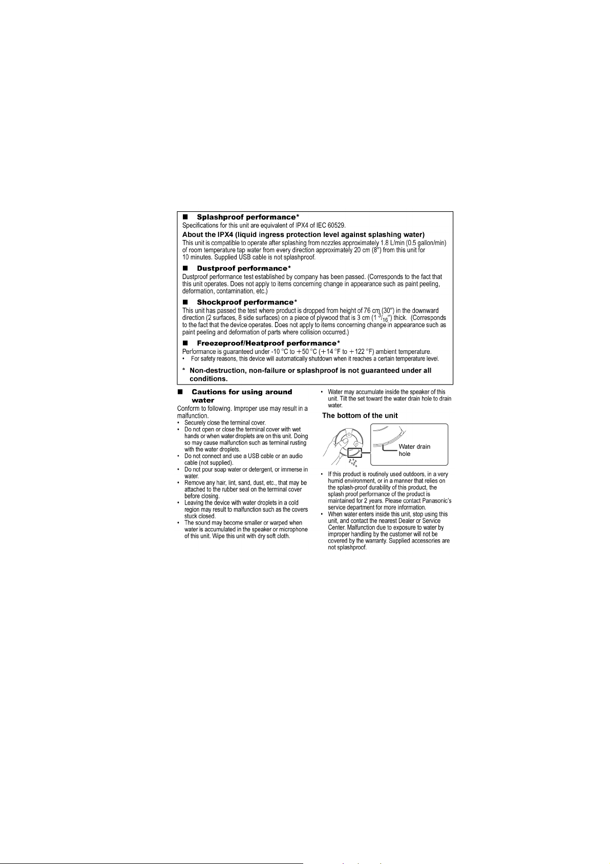
3.2. About the splashproof, dustproof, shockproof
and freezeproof/heatproof------------------------------- 7
4 Specifications ----------------------------------------------------- 8
4.1. Others (Licenses)------------------------------------------ 8
5 General/Introduction -------------------------------------------- 9
5.1. About the power of this unit----------------------------- 9
PAGE PAGE
5.2. Listening to audio from a Bluetooth® device------ 10
5.3. One-Touch Connection (Connecting by NFC)---- 10
6 Location of Controls and Components------------------ 11
6.1. Main Unit Key Button Operations-------------------- 11
7 Troubleshooting Guide --------------------------------------- 12
8 Disassembly and Assembly Instructions---------------13
8.1. Types of Screws------------------------------------------13
8.2. Main Parts Location Diagram------------------------- 14
8.3. Disassembly of Bottom Cover ------------------------15
8.4. Disassembly of Bottom Cabinet Block-------------- 16
8.5. Disassembly of Bottom Cabinet & Passive
Radiator ---------------------------------------------------- 17
8.6. Disassembly of Battery--------------------------------- 17
8.7. Disassembly of Mid Chassis Block------------------ 19
8.8. Disassembly of Cabinet Oring------------------------ 20
© Panasonic Corporation 2013. All rights reserved.
Unauthorized copying and distribution is a violation of
law.

8.9. Disassembly of Chassis Packing & Mid
Chassis Assembly ---------------------------------------21
8.10. Disassembly of Main P.C.B.---------------------------21
8.11. Disassembly of NFC P.C.B. ---------------------------23
8.12. Disassembly of Mic--------------------------------------24
8.13. Disassembly of Button----------------------------------25
8.14. Disassembly of Top Cover-----------------------------25
9 Schematic Diagram---------------------------------------------27
9.1. Schematic Diagram Notes-----------------------------27
9.2. MAIN (AUDIO IN) CIRCUIT ---------------------------29
9.3. MAIN (MICON) CIRCUIT-------------------------------30
9.4. MAIN (D-AMP) CIRCUIT-------------------------------31
9.5. MAIN (POWER) CIRCUIT -----------------------------32
9.6. NFC CIRCUIT---------------------------------------------33
10 Printed Circuit Board ------------------------------------------34
10.1. MAIN P.C.B.-----------------------------------------------34
10.2. NFC P.C.B.-------------------------------------------------35
11 Appendix Information of Schematic Dia gram---------37
1 1 .1. Voltage Measurement & Wavefor m Chart---------37
12 Exploded View and Replacement Parts List-----------41
12.1. Exploded View and Mechanical replacement
Parts List ---------------------------------------------------41
12.2. Electrical Replacement Parts List--------------------45
2
1 Safety Precautions
1.1. General Guidelines
1. IMPORTANT SAFETY NOTICE
There are special components used in this equipment which are important for safety. These parts are marked by in the
Schematic Diagrams, Circuit Board Layout, Exploded Views and Replacement Parts List. It is essential that these critical parts
should be replaced with manufacturer’s specified parts to prevent X-RADIATION, shock, fire, or other hazards. Do not modify
the original design without permission of manufacturer.
2. An Isolation Transformer should always be used during the servicing of AC Adaptor whose chassis is not isolated from the AC
power line. Use a transformer of adequate power rating as this protects the technician from accidents resulting in personal
injury from electrical shocks. It will also protect AC Adaptor from being damaged by accidental shorting that may occur during
servicing.
3. When servicing, observe the original lead dress. If a short circuit is found, re place all parts which have been overheated or
damaged by the short circuit.
4. After servicing, see to it that all the protective devices such as insulation barriers, insulation papers shields are properly
installed.
5. After servicing, make the following leakage current checks to prevent the customer from being exposed to shock hazards.
1.1.1. Leakage Current Cold Check
1. Unplug the AC cord and connect a jumper between the two prongs on the plug.
2. measure the resistance value, with an ohmmeter between the jumpered AC plug a nd each exposed metallic cabinet part on
the equipment such as screwheads, connectors, control shafts, etc. When the exposed metallic part has a return path to the
chassis, the reading should be between 1MΩ and 5.2MΩ. Whe n the exposed me tal does not have a retu rn path to the chas-
sis, the reading must be
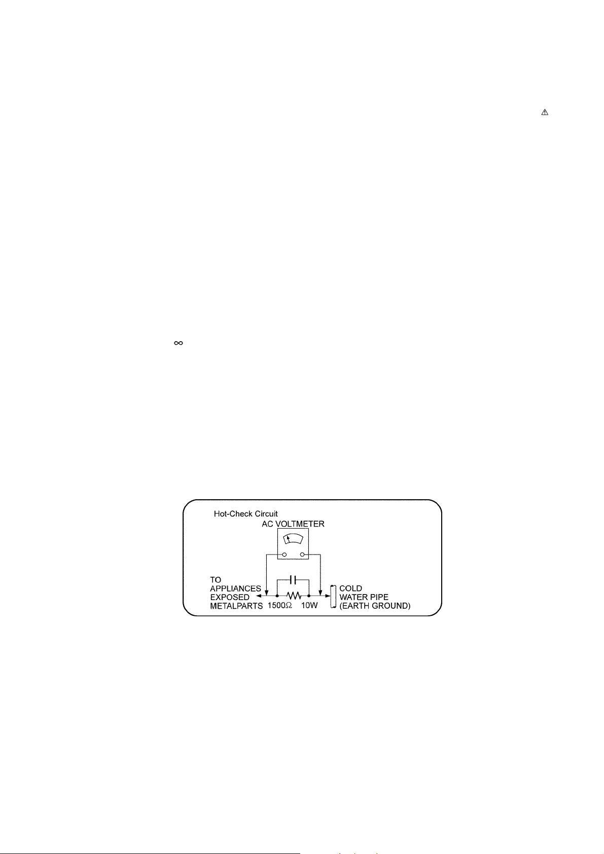
1.1.2. Leakage Current Hot Check
1. Plug the AC cord directly into the AC outlet. Do not use an isolation transformer for this check.
2. Connect a 1.5kΩ, 10 watts resistor, in parallel with a 0.15μF capacitors, between each exposed metallic part on the set and a
good earth ground such as a water pipe, as shown in Figure 1-1.
3. Use an AC voltmeter, with 1000 ohms/volt or more sensitivity, to measure the potential across the resistor.
4. Check each exposed metallic part, and measure the voltage at each point.
5. Reverse the AC plug in the AC outlet and repeat each of the above measurements.
6. The potential at any point should not exceed 0.75 volts RMS. A leakage current tester (Simpson Model 229 or equiva lent)
may be used to make the hot checks, leakage current must not exceed 1/2 milliamp. In case a measurement is outside of the
limits specified, there is a possibility of a shock hazard, and the equipment sho uld be repaired and rechecked before it is
returned to the customer.
Figure 1-1
3

1.2. Protection Circuitry
The protection circuitry may have operated if either of the following conditions are noticed:
• No sound is heard when the power is turned on.
• Sound stops during a performance.
The function of this circuitry is to prevent circuitry damage if, for example, the positive and negative speaker connection wir es are
"shorted", or if speaker systems with an impedance less than the indicated rated impedance of the amplifier are used.
If this occurs, follow the procedure outlines below:
1. Turn off the power.
2. Determine the cause of the problem and correc t it.
3. Turn on the power once again after one minute.
Note:
When the protection circuitry functions, the unit will not operate unless the power is first turned off and then on again.
1.3. Safety Part Information
Safety Parts List:
There are special components used in this equipment which are important for safety.
These parts are marked by in the Schematic Diagrams, Exploded View & Replacement Parts List. It is essential that these
critical parts should be replaced with manufacturer’s specified parts to prevent shock, fire or other hazards. Do not modify the
original design without permission of manufacturer.
Safety Ref. No. Part No. Part Name & Description Remarks
1 BK-15F3G1 BATTERY P/PC
1 BK-15F3G1A BATTERY E
12 RKS0530-A1 BOTTOM CABINET P-A
12 RKS0530A-A1 BOTTOM CABINET PC-A
12 RKS0530B-A BOTTOM CABINET E-A
12 RKS0530-D1 BOTTOM CABINET P-D
12 RKS0530A-D1 BOTTOM CABINET PC-D
12 RKS0530B-D BOTTOM CABINET E-D
A2 VQT5A86 O/I BOOK (En) P/PC
A2 VQT5A88 O/I BOOK (Cf) PC
A2 VQT5A89 O/I BOOK (En/Ge/Fr/It/Sp/Du) E
A2 VQT5A90 O/I BOOK (Sw/Da/Fi/Ru/Ur) E
IP1101 ERBRE2R00V CHIP FUSE
4
2Warning
2.1. Prevention of Electrostatic Discharge (ESD) to Electrostatically Sensitive (ES) Devices
Some semiconductor (solid state) devices can be damaged easily by static electricity. Such components commonly are called Electrostatically Sensitive (ES) Devices.
The following techniques should be used to help reduce the incidence of compon ent damage caused by electrostatic discharge
(ESD).
1. Immediately before handling any semiconductor component or semiconductor-equipped assembly, drain off any ESD on your
body by touching a known earth ground. Alternatively, obtain and wear a commercially available discharging ESD wrist strap,
which should be removed for potential shock reasons prior to applying power to the unit under test.
2. After removing an electrical assembly equipped with ES devices, place the assembly on a condu ctive surface such as aluminum foil, to prevent electrostatic charge buildup or exposure of the assembly.
3. Use only a grounded-tip soldering iron to solder or unsolder ES devices.
4. Use only an anti-static solder removal device. Some solder removal devices not classified as “anti-static (ESD protected)” can
generate electrical charge sufficient to damage ES devices.
5. Do not use freon-propelled chemicals. These can generate electrical charges sufficient to damage ES devices.
6. Do not remove a replacement ES device from its protective package until immediately before you are ready to install it. (Most
replacement ES devices are packaged with leads electrically shorted together by conductive foam, aluminum foil or comparable conductive material).
7. Immediately before removing the protective material from the leads of a replacement ES device, touch the protective material
to the chassis or circuit assembly into which the device will be installed.
CAUTION:
Be sure no power is applied to the chassis or circuit, and observe all other safety precautions.
8. Minimize bodily motions when handling unpackaged replacement ES devices. (Otherwise harmless motion such as the
brushing together of your clothes fabric or the lifting of your foot from a carpeted floor can generate static electricity (ESD) sufficient to damage an ES device).
5

2.2. Service caution based on Legal restrictions
2.2.1. General description about Lead Free Solder (PbF)
The lead free solder has been used in the mounting process of all electrical comp onents on the printed circuit boards us ed for this
equipment in considering the globally environmental conservation.
The normal solder is the alloy of tin (Sn) and lead (Pb). On the other hand, the lead free solder is the alloy mainly consists of tin
(Sn), silver (Ag) and Copper (Cu), and the melting point of the lead free solder is higher approx.30 degrees C (86°F) more than that
of the normal solder.
Definition of PCB Lead Free Solder being used
The letter of “PbF” is printed either foil side or components side on the PCB using the lead free solder.
(See right figure)
Service caution for repair work using Lead Free Solder (PbF)
• The lead free solder has to be used when repairing the equipment for which the lead free solder is used.
(Definition: The letter of “PbF” is printed on the PCB using the lead free solder.)
• To put lead free solder, it should be well molten and mixed with the original lead free solder.
• Remove the remaining lead free solder on the PCB cleanly for soldering of the new IC.
• Since the melting point of the lead free solder is high er than that of the normal lead solder, it takes the longer time to melt the
lead free solder.
• Use the soldering iron (more than 70W) e quipped with the tempe rature control after setting the te mperature at 350±30 degrees
C (662±86°F).
Recommended Lead Free Solder (Service Parts Route.)
• The following 3 types of lead free solder are available through the service parts route.
RFKZ03D01K-----------(0.3mm 100g Reel)
RFKZ06D01K-----------(0.6mm 100g Reel)
RFKZ10D01K-----------(1.0mm 100g Reel)
Note
* Ingredient: Tin (Sn), 96.5%, Silver (Ag) 3.0%, Copper (Cu) 0.5%, Cobalt (Co) / Germanium (Ge) 0.1 to 0.3%
6
3 Service Navigation
3.1. Service Information
This service manual contains technical information which will allow service personnel’s to understand and service this model.
Please place orders using the parts list and not the drawing reference numbers.
If the circuit is changed or modified, this information wil l be followed by supp lement service ma nual to be filed with original servic e
manual.
3.2. About the splashproof, dustproof, shockproof and freezeproof/heatproof
7

4 Specifications
Q Amplifier Section
Output power:
RMS Output Power
10% total harmonic distortion
Front ch (both ch driven): 2 W per channel (1 kHz, 6 Ω,
Boost Mode)
Total RMS power 4 W
(For P/PC only)
FTC Output Power
10% total harmonic distortion
Front ch (both ch driven): 110 Hz - 20kHz 1.4W per channel
(6 Ω, Boost Mode)
Total FTC power 2.8 W
Q Speaker Section
Front Speaker (L/R)
Type 1 way, 1 speaker system
(Passive Radiator)
Unit(s) Ø 34 mm (1 3/8”)
Impedance 6 Ω
Passive Radiator Ø 50 mm (2”)
• Specifications are subject to change without notice.
Mass and dimensions are approximate.
• Total harmonic distortion is measured by the digital spectrum analyzer.
Notes on Speaker:
• Decrease the volume when the audio is distorted.
4.1. Others (Licenses)
Q Bluetooth
Bluetooth
tion:
Wireless equipment classification:
Supported profiles: A2DP/AVRCP/HFP
Supported codec: SBC
Frequency band: 2.4 GHz band FH-SS
Operating distance: Approx. 10 m (33 ft.) Line of Sight
Q Microphone Section
Type: Mono
Q Terminal Section
DC In: USB Micro Type B
AUX input: Stereo, 3.5 mm (1/8”) jack
Q General
Power supply:
(For P/PC) DC IN 5 V 0.6 A
(For E) DC IN 5 V 0.5 A
Battery Life in Use:
Battery Charge Time: Approx. 5 h
Dimensions (W x H x D): 120 mm x 53.8 mm x 120 mm
Mass (Weight): Approx. 330 g (0.73 lbs)
Operating temperature range -10 °C to +50 °C
Operating humidity range 35% to 80 % RH
Splash Proof: IPX4 equivalent
Shock Proof: 76 cm (30”) Drop
®
Section
®
system specifica-
Bluetooth® Ver. 3.0
Class 2 (2.5 mW)
Prospective communication
distance.
Measurement environment:
Hight 1.0 m (3.3 ft.)
Internal Battery 3.6 V (NiMH 1500 mAh)
Approx. 8 h (Normal Mode, Bluetooth
Approx. 1.5 h (Boost Mode, Bluetooth
(4 23/32” x 2 1/8” x 4 23/32”)
(+14 °F to +122 °F)
(no condensation)
®
)
®
)
Note:
8

5 General/Introduction
5.1. About the power of this unit
9
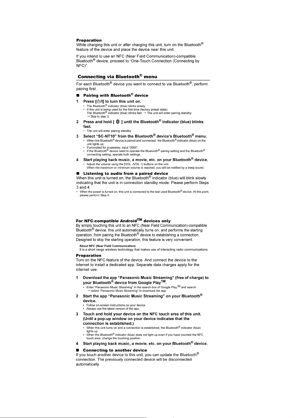
5.2. Listening to audio from a Bluetooth® device
5.3. One-Touch Connection (Connecting by NFC)
10
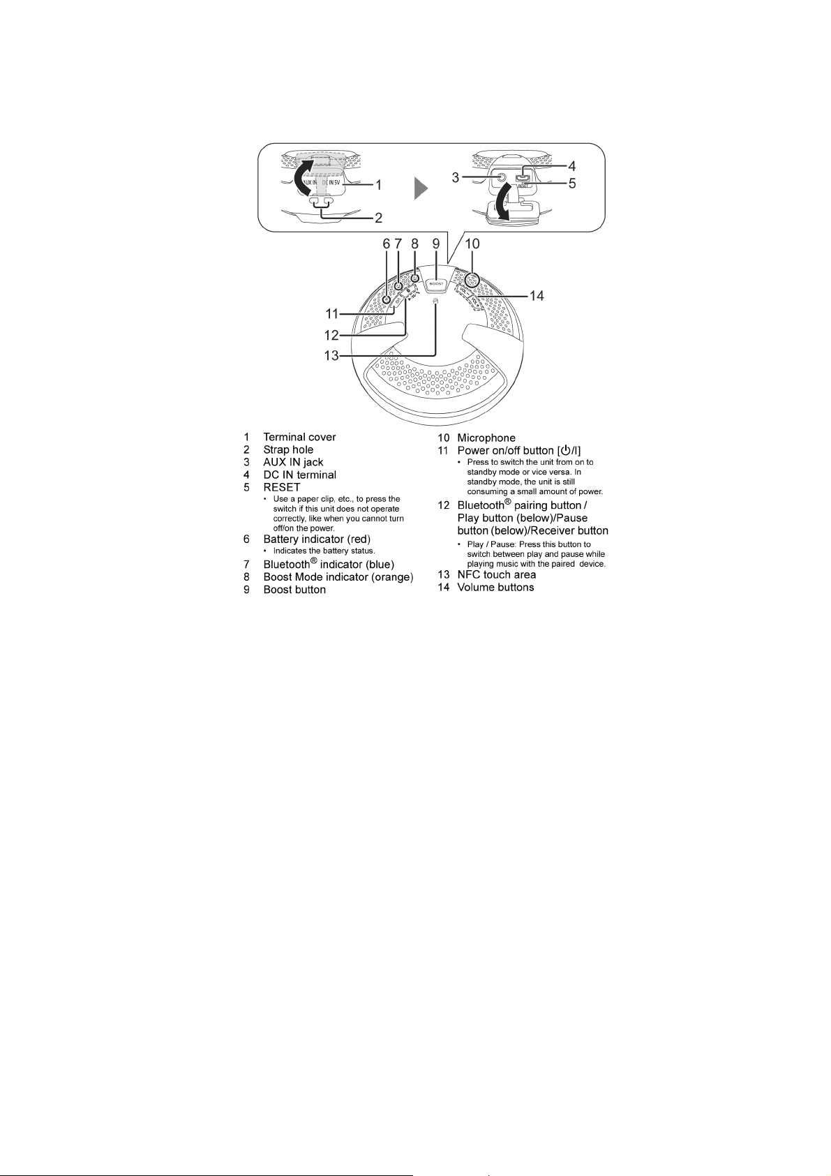
6 Location of Controls and Components
6.1. Main Unit Key Button Operations
11

7 Troubleshooting Guide
This section is not available at the time of issue
12

8 Disassembly and Assembly Instructions
Caution Note:
• This section describes the disassembly and/or assembly procedures for all major printed circuit boards & main components for the unit. (You may refer to the section of “Main components and P.C.B Locations” as described in the service
manual)
• Before carrying out the disassembly process, please ensure all the safety precautions & procedures are followed.
• During the disassembly and/or assembly p rocess, please handle with care as there may be chassis components with
sharp edges.
• Avoid touching heatsinks due to its high temperature after prolong use. (See caution as described below)
• During disassembly and assembly, please ensure proper service tools, equipments or jigs is being used.
• During replacement of component parts, please refer to the section of “Replacement Parts List” as described in the service manual.
• Select items from the following indexes when disassembly or replacement are required.
• Disassembly of Bottom Cover
• Disassembly of Bottom Cabinet Block
• Disassembly of Bottom Cabinet & Passive Radiator
• Disassembly of Battery
• Disassembly of Mid Chassis Block
• Disassembly of Cabinet Oring
• Disassembly of Chassis Packing & Mid Chassis Assembly
• Disassembly of Main P.C.B.
• Disassembly of NFC P.C.B.
• Disassembly of Mic
• Disassembly of Button
• Disassembly of Top Cover
8.1. Types of Screws
13

8.2. Main Parts Location Diagram
14
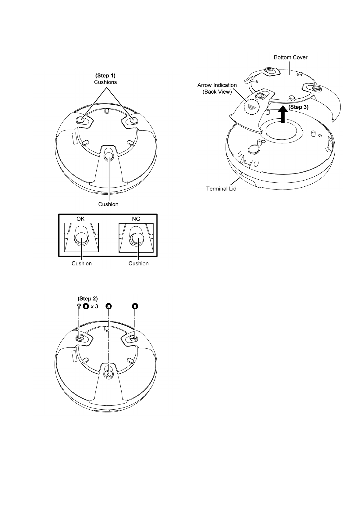
8.3. Disassembly of Bottom Cover
Step 1 : Remove 3 Cushions.
Caution : Replace the Cushions if they lo st their stickines
during disassembling.
Step 3 : Remove the Bottom Cover.
Caution : During assembling, fix the Bottom Cover with the
Arrow indication facing the Terminal Lid.
Step 2 : Remove 3 screws.
15
 Loading...